US4461376A - Clutch driven plate assembly with multi-part hub - Google Patents
Clutch driven plate assembly with multi-part hub Download PDFInfo
- Publication number
- US4461376A US4461376A US06/346,313 US34631382A US4461376A US 4461376 A US4461376 A US 4461376A US 34631382 A US34631382 A US 34631382A US 4461376 A US4461376 A US 4461376A
- Authority
- US
- United States
- Prior art keywords
- hub
- assembly
- clutch
- plate
- flange
- Prior art date
- Legal status (The legal status is an assumption and is not a legal conclusion. Google has not performed a legal analysis and makes no representation as to the accuracy of the status listed.)
- Expired - Fee Related
Links
Images


Classifications
-
- F—MECHANICAL ENGINEERING; LIGHTING; HEATING; WEAPONS; BLASTING
- F16—ENGINEERING ELEMENTS AND UNITS; GENERAL MEASURES FOR PRODUCING AND MAINTAINING EFFECTIVE FUNCTIONING OF MACHINES OR INSTALLATIONS; THERMAL INSULATION IN GENERAL
- F16F—SPRINGS; SHOCK-ABSORBERS; MEANS FOR DAMPING VIBRATION
- F16F15/00—Suppression of vibrations in systems; Means or arrangements for avoiding or reducing out-of-balance forces, e.g. due to motion
- F16F15/10—Suppression of vibrations in rotating systems by making use of members moving with the system
- F16F15/12—Suppression of vibrations in rotating systems by making use of members moving with the system using elastic members or friction-damping members, e.g. between a rotating shaft and a gyratory mass mounted thereon
- F16F15/121—Suppression of vibrations in rotating systems by making use of members moving with the system using elastic members or friction-damping members, e.g. between a rotating shaft and a gyratory mass mounted thereon using springs as elastic members, e.g. metallic springs
-
- F—MECHANICAL ENGINEERING; LIGHTING; HEATING; WEAPONS; BLASTING
- F16—ENGINEERING ELEMENTS AND UNITS; GENERAL MEASURES FOR PRODUCING AND MAINTAINING EFFECTIVE FUNCTIONING OF MACHINES OR INSTALLATIONS; THERMAL INSULATION IN GENERAL
- F16D—COUPLINGS FOR TRANSMITTING ROTATION; CLUTCHES; BRAKES
- F16D13/00—Friction clutches
- F16D13/58—Details
- F16D13/60—Clutching elements
- F16D13/64—Clutch-plates; Clutch-lamellae
- F16D13/644—Hub construction
-
- F—MECHANICAL ENGINEERING; LIGHTING; HEATING; WEAPONS; BLASTING
- F16—ENGINEERING ELEMENTS AND UNITS; GENERAL MEASURES FOR PRODUCING AND MAINTAINING EFFECTIVE FUNCTIONING OF MACHINES OR INSTALLATIONS; THERMAL INSULATION IN GENERAL
- F16D—COUPLINGS FOR TRANSMITTING ROTATION; CLUTCHES; BRAKES
- F16D3/00—Yielding couplings, i.e. with means permitting movement between the connected parts during the drive
- F16D3/02—Yielding couplings, i.e. with means permitting movement between the connected parts during the drive adapted to specific functions
- F16D3/12—Yielding couplings, i.e. with means permitting movement between the connected parts during the drive adapted to specific functions specially adapted for accumulation of energy to absorb shocks or vibration
-
- F—MECHANICAL ENGINEERING; LIGHTING; HEATING; WEAPONS; BLASTING
- F16—ENGINEERING ELEMENTS AND UNITS; GENERAL MEASURES FOR PRODUCING AND MAINTAINING EFFECTIVE FUNCTIONING OF MACHINES OR INSTALLATIONS; THERMAL INSULATION IN GENERAL
- F16F—SPRINGS; SHOCK-ABSORBERS; MEANS FOR DAMPING VIBRATION
- F16F15/00—Suppression of vibrations in systems; Means or arrangements for avoiding or reducing out-of-balance forces, e.g. due to motion
- F16F15/10—Suppression of vibrations in rotating systems by making use of members moving with the system
- F16F15/12—Suppression of vibrations in rotating systems by making use of members moving with the system using elastic members or friction-damping members, e.g. between a rotating shaft and a gyratory mass mounted thereon
- F16F15/1207—Suppression of vibrations in rotating systems by making use of members moving with the system using elastic members or friction-damping members, e.g. between a rotating shaft and a gyratory mass mounted thereon characterised by the supporting arrangement of the damper unit
-
- F—MECHANICAL ENGINEERING; LIGHTING; HEATING; WEAPONS; BLASTING
- F16—ENGINEERING ELEMENTS AND UNITS; GENERAL MEASURES FOR PRODUCING AND MAINTAINING EFFECTIVE FUNCTIONING OF MACHINES OR INSTALLATIONS; THERMAL INSULATION IN GENERAL
- F16D—COUPLINGS FOR TRANSMITTING ROTATION; CLUTCHES; BRAKES
- F16D13/00—Friction clutches
- F16D13/58—Details
- F16D2013/581—Securing means for transportation or shipping
Definitions
- the present invention comprehends the provision of a clutch driven plate assembly in a friction clutch between a vehicle engine and a manual transmission therefor having a novel hub construction to dissipate engine impulses which would normally produce objectionable gear rattle in the transmission when in neutral position with the clutch engaged and the engine at idle rpm.
- the hub assembly includes an inner hub in splined engagement with the transmission input shaft, and an outer hub in splined engagement with the inner hub through helical splines or gear teeth to allow relative axial reciprocation between the hubs to dissipate the engine impulses; the outer hub having a radial flange sandwiched between clutch and spring retainer plates of the assembly.
- the inner hub is formed of a non-metallic, resilient impact absorbing material, or a spacer of such a material is inserted between the inner and outer hubs, and means are provided to dam gear lubricant in the helical gear teeth or splines to prevent migration when subjected to centrifugal force during operation.
- the present invention also comprehends the provision of a clutch driven plate assembly in a friction clutch for an automotive vehicle having a novel hub assembly including an inner hub with inner axial splines and exterior helical splines and an outer hub having internal helical splines and a radially extending flange.
- the outer hub also has end plates which limit the axial movement of the inner hub within the outer hub and act as a dam to retain the lubricant between the helical splines or teeth.
- the present invention further comprehends the provision of a clutch driven plate assembly having a novel hub assembly having inner and outer hubs connected by helical splines, and wherein lubricant is retained between the splines by a flexible shield having an inwardly extending lip to engage the end of the transmission input shaft projecting through the inner hub.
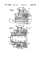
- FIG. 1 is a rear elevational view of a clutch plate assembly incorporating the present invention therein.
- FIG. 2 is a cross sectional view of the clutch plate assembly taken on line 2--2 of FIG. 1.
- FIG. 3 is an enlarged partial cross-sectional view of the hub assembly of FIG. 2.
- FIG. 4 is an enlarged partial cross-sectional view similar to FIG. 3 but showing an alternate embodiment of hub assembly.
- FIG. 5 is an enlarged partial cross-sectional view of a third embodiment of hub assembly.
- FIG. 6 is an enlarged partial cross-sectional view of a fourth embodiment of hub assembly.
- FIGS. 1 and 2 disclose a clutch driven plate assembly 10 for use in a driveline in an automotive vehicle between the engine and the manual transmission (not shown).
- the clutch plate assembly includes a hub assembly 11 in splined engagement with the splined end 13 of a transmission input shaft 12, and a clutch plate 14 and a spring retainer plate 27 secured together in spaced relation and journalled on the hub assembly.
- the clutch plate 14 is a generally flat plate having a central opening 15 receiving the hub, a plurality of arcuate spring windows 16 with inner and outer lips 17 and 18 acting to retain damper springs 19 therein, a plurality of openings 21 to receive one end of spacer rivets 22, and a plurality of openings 23 adjacent the plate periphery.
- a plurality of spring cushions 25 carrying the friction facings 26,26 are secured to the clutch plate through rivets 24 in the openings 23.
- the spring retainer plate 27 is also a generally flat disc having a central opening 28, a plurality of spring windows 29 with inner and outer lips 31 and 32, and a plurality of openings 33 receiving the opposite ends of the spacer rivets 22.
- the spring windows 16 and 29 of the plates 14 and 27 and the openings 21 and 33 are axially aligned for the two plates for reception of the damper springs and spacer rivets, respectively.
- the hub assembly 11 includes an inner hub or barrel 34 and an outer hub 41; the inner hub barrel having internal axially extending splines 35 engaging the splined end 13 of shaft 12, and a radial flange 36 formed at the rear end of the barrel has external helical splines 37 thereon.
- the hub barrel is preferably formed of a non-metallic, impact absorbing material, such as nylon with 30% glass fibers which is light in weight, self-lubricating and inexpensively molded.
- the rear face of the flange 36 has a plurality of circumferentially spaced axially extending holes 38 containing coil springs 39 that urge the inner hub forwardly relative to the outer hub.
- the outer hub 41 has a generally cylindrical body 42 with internal helical splines 43 meshing with the splines 37 and counterbored at each end 44 to receive end plates 45 and 46 positioned at the ends of splines 43. Once in place, the ends 44 are crimped or spun over at 47 to retain the plates in the resulting annular grooves.
- the end plate 46 has a smaller diameter central opening 48 so that the plate will form an abutment for the ends of the coil springs 39 extending from the holes 38.
- a radial flange 49 is integral with the body 42 and is provided with damper spring windows 51 axially aligned with the windows 16 and 29 and a plurality of peripheral notches 52 through which the spacer rivets 22 extend.
- the notches are of such an arcuate length as to provide limited lost motion between the joined plates 14 and 27 and the flange 49 when the springs 19 are under load.
- Friction washers 53 may be positioned between the plates and hub flange to provide additional frictional damping.
- the springs 39 are compressed, and the material of the inner hub is sufficiently resilient to absorb the impact and sound produced when the hub strikes either end plate 45 or 46.
- the material forming the inner hub may be self-lubricating or may be lubricated with a suitable lubricant, such as Dow Corning's "Molykote G-n". Where a lubricant is utilized between the helical splines or gear teeth, the end plates 45 and 46 act as a dam to prevent migration of any lubricant from the splines when the assembly is subjected to centrifugal force in operation.
- FIG. 4 discloses an alternate embodiment of damper hub assembly 55 wherein like parts will be denoted by the same reference numeral with a script a.
- the inner hub 34a is identical with the inner hub 34 of FIGS. 1 through 3 with the internal axial splines 35a and the external helical splines 37a.
- the outer hub 41a is similar to the outer hub of FIGS. 1-3 except for an inwardly extending end flange 56 in place of the end plate 45.
- the inner hub 34a reciprocates between the flange 56 and the end plate 46a, with the coil springs 39a biasing the inner hub toward the end flange 56.
- This hub is formed of the same non-metallic, impulse absorbing material as the inner hub 34 and the intermeshing helical splines may have lubricant, as desired.
- FIG. 5 discloses a third embodiment of hub assembly 61 wherein the inner hub 34b is identical with the hub 34 of FIGS. 1 through 3 except it is formed of a conventional metal.
- the outer hub 41b is generally similar to that of FIGS. 1 through 3 except for a pilot diameter 62 at the ends of the internal helical splines 43b to receive a generally annular spacer 63 with internal axial splines or gear teeth 64 and a plurality of holes 65 axially aligned with the holes 38b in the inner hub 34b.
- Coil springs 39b project from the inner hub through the holes 65 to engage the end plate 46b; the spacer 63 being located between the ends of the helical splines 43b end plate 46b.
- the spacer 63 is formed of an impact and sound absorbing material, such as that disclosed for inner hub 34.
- the springs 39b pilot in the holes 38b and pass through the holes 65 which are in alignment to index the spline teeth 64 to the spline teeth 35b for assembly purposes.
- This assembly operates in the same manner as that shown in FIGS. 1 through 3 except that the impact and sound are absorbed in the spacer 63 when the inner hub 34b strikes it.
- the spacer 63 pilots the outer hub 41b concentric to the diameter 62 to reduce binding in the helical gear teeth or splines. Suitable lubricant is provided for the helical gear teeth and is contained in the gear mesh by the end plates 45b,46b which act as a dam to prevent migration when the assembly is subjected to centrifugal force in operation.
- FIG. 6 relates to a fourth embodiment of hub assembly 68 similar to the assembly of FIG. 5.
- the inner hub 34c is substantially identical to that shown in FIGS. 1 through 3, except it is formed of metal and has a plurality of circumferentially spaced holes 69 in the shoulder 71 formed by the flange 36c opening forwardly toward the end plate 45c and housing coil springs 70. Also, adjacent the forward end of the inner hub, an annular groove 72 is formed in the outer surface 73 to receive an annular lip 75 on a resilient shield 74, which also has an inwardly directed sealing lip 76.
- the internal helical splines 43c in the outer hub 41c terminates short of both end plates 45c,46c.
- a non-metallic impact absorbing spacer 63c is located between the end of the splines 43c and the end plate 46c in the same manner as shown in FIG. 5, while a second annular non-metallic impact absorbing spacer 77 is located between end plate 45c and the forward ends of the helical splines 43c.
- a plug 78 having a forward closed end 79 and a rearward radial flange 81 is inserted in the inner hub 34c and spacer 63c to engage the inner splines 35c and 64c, respectively, to retain lubricant in the assembly during handling and shipping, and the plug is removed before the transmission shaft is inserted.
- the lip 76 of the resilient shield 74 engages the outer surface of the end of the transmission shaft projecting through the hub 34c, such that the shield captures any lubricant that migrates out of the splines 35c.
- the lip 76 extends below the root of the transmission shaft spline to capture any lubricant from the mesh to be retained in the area 82.
- This assembly operates in an identical fashion to the structure shown in FIG. 5, except it has a gap 83 to provide a coast travel for the hub 34c which compresses the springs 70 before striking the impact absorbing spacer 77.
- the purpose of the spring loaded coast travel is to absorb impulses when the vehicle engine reverses itself for a portion of a normal rotation during rough idle periods.
Landscapes
- Engineering & Computer Science (AREA)
- General Engineering & Computer Science (AREA)
- Mechanical Engineering (AREA)
- Physics & Mathematics (AREA)
- Acoustics & Sound (AREA)
- Aviation & Aerospace Engineering (AREA)
- Mechanical Operated Clutches (AREA)
Priority Applications (9)
| Application Number | Priority Date | Filing Date | Title |
|---|---|---|---|
| US06/346,313 US4461376A (en) | 1982-02-05 | 1982-02-05 | Clutch driven plate assembly with multi-part hub |
| EP83300229A EP0086044B1 (fr) | 1982-02-05 | 1983-01-18 | Disque mené d'embrayage à moyeu en plusieurs parties |
| DE8383300229T DE3364792D1 (en) | 1982-02-05 | 1983-01-18 | Clutch driven plate assembly with multi-part hub |
| AU10699/83A AU557038B2 (en) | 1982-02-05 | 1983-01-24 | Clutch driven plate assembly with multi-part hub |
| CA000420709A CA1213839A (fr) | 1982-02-05 | 1983-02-01 | Plateau a moyeu multipiece entraine par embrayage |
| JP58014712A JPS58134231A (ja) | 1982-02-05 | 1983-02-02 | 多部品ハブを有するクラツチ被駆動プレ−ト組立体 |
| BR8300559A BR8300559A (pt) | 1982-02-05 | 1983-02-04 | Unidade de placa acionada por embreagem |
| ES519540A ES8402643A1 (es) | 1982-02-05 | 1983-02-04 | Un dispositivo de plato accionado de embrague, para un embrague de vehiculo automovil. |
| AR292037A AR230675A1 (es) | 1982-02-05 | 1983-02-04 | Mejoras en un conjunto de placa impulsada de embrague para un embrague de vehiculo automotor |
Applications Claiming Priority (1)
| Application Number | Priority Date | Filing Date | Title |
|---|---|---|---|
| US06/346,313 US4461376A (en) | 1982-02-05 | 1982-02-05 | Clutch driven plate assembly with multi-part hub |
Publications (1)
| Publication Number | Publication Date |
|---|---|
| US4461376A true US4461376A (en) | 1984-07-24 |
Family
ID=23358836
Family Applications (1)
| Application Number | Title | Priority Date | Filing Date |
|---|---|---|---|
| US06/346,313 Expired - Fee Related US4461376A (en) | 1982-02-05 | 1982-02-05 | Clutch driven plate assembly with multi-part hub |
Country Status (9)
| Country | Link |
|---|---|
| US (1) | US4461376A (fr) |
| EP (1) | EP0086044B1 (fr) |
| JP (1) | JPS58134231A (fr) |
| AR (1) | AR230675A1 (fr) |
| AU (1) | AU557038B2 (fr) |
| BR (1) | BR8300559A (fr) |
| CA (1) | CA1213839A (fr) |
| DE (1) | DE3364792D1 (fr) |
| ES (1) | ES8402643A1 (fr) |
Cited By (24)
| Publication number | Priority date | Publication date | Assignee | Title |
|---|---|---|---|---|
| US4537580A (en) * | 1982-09-07 | 1985-08-27 | Valeo | Torsional damper device |
| US4537296A (en) * | 1984-07-23 | 1985-08-27 | Alma Piston Company | Clutch driven plate assembly |
| US4537579A (en) * | 1982-09-07 | 1985-08-27 | Valeo | Torsional damper device |
| US4556136A (en) * | 1983-11-30 | 1985-12-03 | Borg-Warner Corporation | Clutch driven plate assembly |
| US4615426A (en) * | 1983-11-30 | 1986-10-07 | Borg-Warner Corporation | Clutch driven plate assembly |
| US4637500A (en) * | 1982-05-14 | 1987-01-20 | Fichtel & Sachs Ag | Hydrodynamic coupling with serially arranged damper units |
| US4787612A (en) * | 1986-04-30 | 1988-11-29 | Automotive Products Plc | Torsional vibration damper |
| US5246399A (en) * | 1991-12-11 | 1993-09-21 | Borg-Warner Automotive Transmission & Engine Components Corporation | Two-stage torsional vibration damper |
| US5588518A (en) * | 1994-03-09 | 1996-12-31 | Fichtel & Sachs Ag | Clutch disc with a reinforced hub |
| US5617939A (en) * | 1994-08-23 | 1997-04-08 | Fichtel & Sachs Ag | Friction clutch assembly for a motor vehicle, the friction clutch assembly having a clutch plate with divided hub disc |
| US5653144A (en) * | 1993-02-09 | 1997-08-05 | Fenelon; Paul J. | Stress dissipation apparatus |
| US5692410A (en) * | 1993-02-09 | 1997-12-02 | Fenelon; Paul J. | Rotatable apparatus having a stress dissipation structure |
| US5935007A (en) * | 1997-05-29 | 1999-08-10 | Meritor Heavy Vehicle Systems, Llc | Torsional vibration damper |
| US5956998A (en) * | 1996-06-06 | 1999-09-28 | Fenelon; Paul J. | Stress reduction gear and apparatus using same |
| FR2818345A1 (fr) * | 2000-12-15 | 2002-06-21 | Valeo | Dispositif amortisseur de torsion, notamment pour vehicule automobile |
| US20060191761A1 (en) * | 2005-02-28 | 2006-08-31 | Zf Friedrichshafen Ag | Clutch apparatus |
| US20090032364A1 (en) * | 2007-07-25 | 2009-02-05 | Luk Lamellen Und Kupplungsbau Beteiligungs Kg | Method and apparatus for lash prevention using coil springs |
| US20090159370A1 (en) * | 2007-12-20 | 2009-06-25 | Rolls-Royce Corporation | Dual splined shaft |
| US20110129291A1 (en) * | 2009-12-01 | 2011-06-02 | Ryan Charles Humes | Shaft coupling |
| CN102588454A (zh) * | 2011-01-15 | 2012-07-18 | 奥迪股份公司 | 用于进行驱动连接的装置 |
| US10151354B2 (en) * | 2016-09-09 | 2018-12-11 | Schaeffler Technologies AG & Co. KG | Universal damper and interchangeable hub assembly |
| WO2022020880A1 (fr) * | 2020-07-27 | 2022-02-03 | Clutch Industries Pty Ltd | Ensemble embrayage |
| US11585391B2 (en) | 2020-07-27 | 2023-02-21 | Clutch Industries Pty Ltd | Clutch assembly |
| US11686352B2 (en) | 2020-07-27 | 2023-06-27 | Clutch Industries Pty Ltd | Clutch assembly |
Families Citing this family (8)
| Publication number | Priority date | Publication date | Assignee | Title |
|---|---|---|---|---|
| JPS59103934U (ja) * | 1982-12-28 | 1984-07-12 | 株式会社大金製作所 | クラツチデイスク |
| US4548302A (en) * | 1983-11-30 | 1985-10-22 | Borg-Warner Corporation | Two-stage clutch damper assembly |
| DE3448538C2 (de) * | 1984-11-23 | 1996-08-29 | Luk Lamellen & Kupplungsbau | Torsionsschwingungsdämpfer |
| DE19727678C2 (de) * | 1997-06-30 | 1999-12-16 | Mannesmann Sachs Ag | Torsionsschwingungsdämpfer mit einem Planetengetriebe mit wenigstens einem Verzahnungselement |
| US9500259B1 (en) | 2015-08-11 | 2016-11-22 | Gm Global Technology Operations, Llc | High performance torsional vibration isolator |
| US10006517B2 (en) | 2016-03-03 | 2018-06-26 | GM Global Technology Operations LLC | Torsional vibration damper with planetary gear enhanced by inertial mass |
| US10337562B2 (en) | 2016-06-17 | 2019-07-02 | GM Global Technology Operations LLC | Clutch for a transmission |
| US10323698B2 (en) | 2016-11-01 | 2019-06-18 | GM Global Technology Operations LLC | Torque transferring clutch separation |
Citations (12)
| Publication number | Priority date | Publication date | Assignee | Title |
|---|---|---|---|---|
| US27126A (en) * | 1860-02-14 | Frank i | ||
| US2026733A (en) * | 1932-10-08 | 1936-01-07 | Gustave Fast Engineering Corp | Friction clutch |
| US2276416A (en) * | 1939-07-15 | 1942-03-17 | Borg Warner | Clutch plate |
| US3181673A (en) * | 1963-02-11 | 1965-05-04 | Bendix Corp | Self-energizing overrunning clutch with speed responsive retarder |
| US3299671A (en) * | 1964-01-09 | 1967-01-24 | Renault | Devices for damping angular velocity fluctuations between two rotating components, one of which drives the other |
| US3362194A (en) * | 1965-11-23 | 1968-01-09 | Ford Motor Co | Friction clutch with vibration damper |
| US3428155A (en) * | 1965-12-01 | 1969-02-18 | Fichtel & Sachs Ag | Clutch plate with vibration dampeners in series |
| US3556273A (en) * | 1967-08-19 | 1971-01-19 | Luk Lamellen & Kupplungsbau | Clutch disc with vibration dampeners in series |
| USRE27126E (en) | 1970-05-08 | 1971-05-25 | Dual splinded shaft assembly for a clutch | |
| US4016962A (en) * | 1975-11-03 | 1977-04-12 | Twin Disc, Incorporated | Vibration resistant mechanical clutch |
| US4190142A (en) * | 1977-02-25 | 1980-02-26 | Societe Anonyme Francaise Du Ferodo | Torsion-damping assemblies with two-part hubs e.g. for friction clutches |
| GB2078906A (en) * | 1980-07-03 | 1982-01-13 | Borg Warner | Clutch driven plate assembly with a floating hub |
Family Cites Families (3)
| Publication number | Priority date | Publication date | Assignee | Title |
|---|---|---|---|---|
| GB105982A (en) * | 1916-05-05 | 1917-05-07 | George Enoch Stanley | Improvements in the Driving Mechanism of Motor Cycles and the like. |
| DE810235C (de) * | 1949-11-06 | 1951-08-06 | Gustav Debor | Kardanfederung, insbesondere fuer Kraftfahrzeuge |
| FR1045339A (fr) * | 1950-11-22 | 1953-11-25 | Joint à coulissement élastique, avec amortissement hydraulique |
-
1982
- 1982-02-05 US US06/346,313 patent/US4461376A/en not_active Expired - Fee Related
-
1983
- 1983-01-18 EP EP83300229A patent/EP0086044B1/fr not_active Expired
- 1983-01-18 DE DE8383300229T patent/DE3364792D1/de not_active Expired
- 1983-01-24 AU AU10699/83A patent/AU557038B2/en not_active Ceased
- 1983-02-01 CA CA000420709A patent/CA1213839A/fr not_active Expired
- 1983-02-02 JP JP58014712A patent/JPS58134231A/ja active Pending
- 1983-02-04 ES ES519540A patent/ES8402643A1/es not_active Expired
- 1983-02-04 AR AR292037A patent/AR230675A1/es active
- 1983-02-04 BR BR8300559A patent/BR8300559A/pt not_active IP Right Cessation
Patent Citations (12)
| Publication number | Priority date | Publication date | Assignee | Title |
|---|---|---|---|---|
| US27126A (en) * | 1860-02-14 | Frank i | ||
| US2026733A (en) * | 1932-10-08 | 1936-01-07 | Gustave Fast Engineering Corp | Friction clutch |
| US2276416A (en) * | 1939-07-15 | 1942-03-17 | Borg Warner | Clutch plate |
| US3181673A (en) * | 1963-02-11 | 1965-05-04 | Bendix Corp | Self-energizing overrunning clutch with speed responsive retarder |
| US3299671A (en) * | 1964-01-09 | 1967-01-24 | Renault | Devices for damping angular velocity fluctuations between two rotating components, one of which drives the other |
| US3362194A (en) * | 1965-11-23 | 1968-01-09 | Ford Motor Co | Friction clutch with vibration damper |
| US3428155A (en) * | 1965-12-01 | 1969-02-18 | Fichtel & Sachs Ag | Clutch plate with vibration dampeners in series |
| US3556273A (en) * | 1967-08-19 | 1971-01-19 | Luk Lamellen & Kupplungsbau | Clutch disc with vibration dampeners in series |
| USRE27126E (en) | 1970-05-08 | 1971-05-25 | Dual splinded shaft assembly for a clutch | |
| US4016962A (en) * | 1975-11-03 | 1977-04-12 | Twin Disc, Incorporated | Vibration resistant mechanical clutch |
| US4190142A (en) * | 1977-02-25 | 1980-02-26 | Societe Anonyme Francaise Du Ferodo | Torsion-damping assemblies with two-part hubs e.g. for friction clutches |
| GB2078906A (en) * | 1980-07-03 | 1982-01-13 | Borg Warner | Clutch driven plate assembly with a floating hub |
Non-Patent Citations (2)
| Title |
|---|
| U.S. patent application Ser. No. 212,925, filed Dec. 4, 1980, Thaddeus Lech, Jr. * |
| U.S. patent application Ser. No. 248,106, filed Mar. 27, 1981, Thaddeus Lech, Jr. * |
Cited By (35)
| Publication number | Priority date | Publication date | Assignee | Title |
|---|---|---|---|---|
| US4637500A (en) * | 1982-05-14 | 1987-01-20 | Fichtel & Sachs Ag | Hydrodynamic coupling with serially arranged damper units |
| US4537580A (en) * | 1982-09-07 | 1985-08-27 | Valeo | Torsional damper device |
| US4537579A (en) * | 1982-09-07 | 1985-08-27 | Valeo | Torsional damper device |
| US4556136A (en) * | 1983-11-30 | 1985-12-03 | Borg-Warner Corporation | Clutch driven plate assembly |
| US4615426A (en) * | 1983-11-30 | 1986-10-07 | Borg-Warner Corporation | Clutch driven plate assembly |
| AU568696B2 (en) * | 1983-11-30 | 1988-01-07 | Borg-Warner Corporation | Clutch driven plate assembly |
| US4537296A (en) * | 1984-07-23 | 1985-08-27 | Alma Piston Company | Clutch driven plate assembly |
| US4787612A (en) * | 1986-04-30 | 1988-11-29 | Automotive Products Plc | Torsional vibration damper |
| US5246399A (en) * | 1991-12-11 | 1993-09-21 | Borg-Warner Automotive Transmission & Engine Components Corporation | Two-stage torsional vibration damper |
| US5653144A (en) * | 1993-02-09 | 1997-08-05 | Fenelon; Paul J. | Stress dissipation apparatus |
| US5692410A (en) * | 1993-02-09 | 1997-12-02 | Fenelon; Paul J. | Rotatable apparatus having a stress dissipation structure |
| US5943913A (en) | 1993-02-09 | 1999-08-31 | Fenelon; Paul J. | Rotatable apparatus having a stress dissipation structure |
| US5588518A (en) * | 1994-03-09 | 1996-12-31 | Fichtel & Sachs Ag | Clutch disc with a reinforced hub |
| US5617939A (en) * | 1994-08-23 | 1997-04-08 | Fichtel & Sachs Ag | Friction clutch assembly for a motor vehicle, the friction clutch assembly having a clutch plate with divided hub disc |
| US5956998A (en) * | 1996-06-06 | 1999-09-28 | Fenelon; Paul J. | Stress reduction gear and apparatus using same |
| US5935007A (en) * | 1997-05-29 | 1999-08-10 | Meritor Heavy Vehicle Systems, Llc | Torsional vibration damper |
| FR2818345A1 (fr) * | 2000-12-15 | 2002-06-21 | Valeo | Dispositif amortisseur de torsion, notamment pour vehicule automobile |
| US20060191761A1 (en) * | 2005-02-28 | 2006-08-31 | Zf Friedrichshafen Ag | Clutch apparatus |
| US8096885B2 (en) * | 2007-07-25 | 2012-01-17 | Schaeffler Technologies Gmbh & Co. Kg | Method and apparatus for lash prevention using coil springs |
| US20090032364A1 (en) * | 2007-07-25 | 2009-02-05 | Luk Lamellen Und Kupplungsbau Beteiligungs Kg | Method and apparatus for lash prevention using coil springs |
| US10451169B2 (en) * | 2007-12-20 | 2019-10-22 | Rolls-Royce Corporation | Dual splined shaft |
| US20090159370A1 (en) * | 2007-12-20 | 2009-06-25 | Rolls-Royce Corporation | Dual splined shaft |
| US9677662B2 (en) | 2007-12-20 | 2017-06-13 | Rolls-Royce Corporation | Dual splined shaft |
| US8678937B2 (en) | 2009-12-01 | 2014-03-25 | Rolls-Royce Corporation | Shaft coupling |
| US20110129291A1 (en) * | 2009-12-01 | 2011-06-02 | Ryan Charles Humes | Shaft coupling |
| US8597129B2 (en) * | 2011-01-15 | 2013-12-03 | Audi Ag | Device for a drive connection |
| CN102588454B (zh) * | 2011-01-15 | 2015-06-03 | 奥迪股份公司 | 用于进行驱动连接的装置 |
| US20130045809A1 (en) * | 2011-01-15 | 2013-02-21 | Audi Ag | Device for a drive connection |
| CN102588454A (zh) * | 2011-01-15 | 2012-07-18 | 奥迪股份公司 | 用于进行驱动连接的装置 |
| US10151354B2 (en) * | 2016-09-09 | 2018-12-11 | Schaeffler Technologies AG & Co. KG | Universal damper and interchangeable hub assembly |
| WO2022020880A1 (fr) * | 2020-07-27 | 2022-02-03 | Clutch Industries Pty Ltd | Ensemble embrayage |
| US11585391B2 (en) | 2020-07-27 | 2023-02-21 | Clutch Industries Pty Ltd | Clutch assembly |
| US11655860B2 (en) | 2020-07-27 | 2023-05-23 | Clutch Industries Pty Ltd | Clutch assembly |
| US11686352B2 (en) | 2020-07-27 | 2023-06-27 | Clutch Industries Pty Ltd | Clutch assembly |
| US12590609B2 (en) | 2020-07-27 | 2026-03-31 | Clutch Industries Pty Ltd. | Clutch assembly |
Also Published As
| Publication number | Publication date |
|---|---|
| CA1213839A (fr) | 1986-11-12 |
| DE3364792D1 (en) | 1986-09-04 |
| JPS58134231A (ja) | 1983-08-10 |
| AR230675A1 (es) | 1984-05-31 |
| AU557038B2 (en) | 1986-12-04 |
| EP0086044A1 (fr) | 1983-08-17 |
| EP0086044B1 (fr) | 1986-07-30 |
| AU1069983A (en) | 1983-08-11 |
| ES519540A0 (es) | 1984-02-01 |
| ES8402643A1 (es) | 1984-02-01 |
| BR8300559A (pt) | 1983-11-08 |
Similar Documents
| Publication | Publication Date | Title |
|---|---|---|
| US4461376A (en) | Clutch driven plate assembly with multi-part hub | |
| US4777843A (en) | Two mass flywheel assembly with viscous damping assembly | |
| CA1185907A (fr) | Disque a moyeu en roue libre et entrainement par embrayage | |
| US4413711A (en) | Extended travel damper in a lock-up clutch for a torque converter | |
| US20020135186A1 (en) | Starter equipped with a torque-limiter and damper device | |
| US4874074A (en) | Torsional vibration damping mechanism | |
| US4418812A (en) | Clutch driven plate assembly with a floating hub | |
| EP0294048A2 (fr) | Volant d'inertie en deux parties avec moyens d'amortissement de torsion | |
| EP0104823A1 (fr) | Amortisseur de vibrations de torsion à plusieurs étages | |
| US4471863A (en) | Multi-stage torsional damping device | |
| US5169357A (en) | Torsion damping device, in particular for a clutch friction disc for a motor vehicle | |
| US4303149A (en) | Clutch driven plate with spline locking hub | |
| EP0209314A1 (fr) | Disque mené d'embrayage avec amortissement des rattrapages de jeu | |
| US4555009A (en) | Minimum complexity vibration damper | |
| US4518071A (en) | Clutch disc having damper springs | |
| US6003650A (en) | Torsional vibration damper with a planetary gear set with at least one toothing element | |
| US11339864B2 (en) | Integrated gear and torsional vibration damper assembly | |
| US5119693A (en) | Damped double flywheel, in particular for automotive vehicles | |
| EP0364219A2 (fr) | Procédé pour la fabrication, l'assemblage et le remplissage d'un amortisseur visqueux | |
| EP0304159B1 (fr) | Unité d'amortissement visqueux pour mécanisme d'amortissement de vibration de torsion | |
| EP0146253B1 (fr) | Embrayage avec amortisseur à deux étages | |
| US4679678A (en) | Minimum complexity vibration damper | |
| US4615426A (en) | Clutch driven plate assembly | |
| US4620626A (en) | Clutch driven plate assembly with an anti-rattle damper | |
| US5219431A (en) | Method of forming and stressing composite springs |
Legal Events
| Date | Code | Title | Description |
|---|---|---|---|
| AS | Assignment |
Owner name: BORG-WARNER CORPORATION, 200 SOUTH MICHIGAN AVENUE Free format text: ASSIGNMENT OF ASSIGNORS INTEREST.;ASSIGNORS:LECH, THADDEUS JR.;WEAGE, KENNETH A.;WEAGE, CAROLINE J.;REEL/FRAME:003987/0026 Effective date: 19820128 Owner name: BORG-WARNER CORPORATION, ILLINOIS Free format text: ASSIGNMENT OF ASSIGNORS INTEREST;ASSIGNORS:LECH, THADDEUS JR.;WEAGE, KENNETH A.;WEAGE, CAROLINE J.;REEL/FRAME:003987/0026 Effective date: 19820128 |
|
| CC | Certificate of correction | ||
| FPAY | Fee payment |
Year of fee payment: 4 |
|
| AS | Assignment |
Owner name: BORG-WARNER CORPORATION, A DE CORP. Free format text: ASSIGNMENT OF ASSIGNORS INTEREST. EFFECTIVE AS OF DEC. 31, 1987;ASSIGNOR:BORG-WARNER AUTOMOTIVE, INC., A DE CORP.;REEL/FRAME:005287/0001 Effective date: 19881122 |
|
| FEPP | Fee payment procedure |
Free format text: PAYOR NUMBER ASSIGNED (ORIGINAL EVENT CODE: ASPN); ENTITY STATUS OF PATENT OWNER: LARGE ENTITY Free format text: PAYER NUMBER DE-ASSIGNED (ORIGINAL EVENT CODE: RMPN); ENTITY STATUS OF PATENT OWNER: LARGE ENTITY |
|
| REFU | Refund |
Free format text: REFUND OF EXCESS PAYMENTS PROCESSED (ORIGINAL EVENT CODE: R169); ENTITY STATUS OF PATENT OWNER: LARGE ENTITY |
|
| FPAY | Fee payment |
Year of fee payment: 8 |
|
| REMI | Maintenance fee reminder mailed | ||
| LAPS | Lapse for failure to pay maintenance fees | ||
| FP | Lapsed due to failure to pay maintenance fee |
Effective date: 19960724 |
|
| STCH | Information on status: patent discontinuation |
Free format text: PATENT EXPIRED DUE TO NONPAYMENT OF MAINTENANCE FEES UNDER 37 CFR 1.362 |