US4515040A - Control apparatus and method for engine-continuously variable transmission - Google Patents
Control apparatus and method for engine-continuously variable transmission Download PDFInfo
- Publication number
- US4515040A US4515040A US06/411,987 US41198782A US4515040A US 4515040 A US4515040 A US 4515040A US 41198782 A US41198782 A US 41198782A US 4515040 A US4515040 A US 4515040A
- Authority
- US
- United States
- Prior art keywords
- electric signal
- accelerator pedal
- revolution speed
- generating
- line pressure
- Prior art date
- Legal status (The legal status is an assumption and is not a legal conclusion. Google has not performed a legal analysis and makes no representation as to the accuracy of the status listed.)
- Expired - Lifetime
Links
- 230000005540 biological transmission Effects 0.000 title claims abstract description 52
- 238000000034 method Methods 0.000 title description 6
- 230000009467 reduction Effects 0.000 claims abstract description 101
- 239000000446 fuel Substances 0.000 claims abstract description 88
- 230000004044 response Effects 0.000 claims abstract description 56
- 238000004519 manufacturing process Methods 0.000 claims abstract description 7
- 230000006870 function Effects 0.000 claims description 93
- 239000012530 fluid Substances 0.000 claims description 62
- 238000005086 pumping Methods 0.000 claims description 20
- 230000001105 regulatory effect Effects 0.000 claims description 19
- 230000007423 decrease Effects 0.000 claims description 15
- 230000001276 controlling effect Effects 0.000 claims description 13
- 230000001965 increasing effect Effects 0.000 claims description 13
- 230000003247 decreasing effect Effects 0.000 claims description 11
- 238000002347 injection Methods 0.000 claims description 10
- 239000007924 injection Substances 0.000 claims description 10
- 230000000994 depressogenic effect Effects 0.000 claims description 6
- 238000005192 partition Methods 0.000 claims 2
- 230000010354 integration Effects 0.000 claims 1
- 238000011144 upstream manufacturing Methods 0.000 claims 1
- 238000010276 construction Methods 0.000 description 7
- 238000010586 diagram Methods 0.000 description 7
- 238000006243 chemical reaction Methods 0.000 description 3
- 230000002708 enhancing effect Effects 0.000 description 3
- 230000008859 change Effects 0.000 description 2
- 230000000694 effects Effects 0.000 description 2
- 230000009471 action Effects 0.000 description 1
- 230000002730 additional effect Effects 0.000 description 1
- 230000008901 benefit Effects 0.000 description 1
- 238000002485 combustion reaction Methods 0.000 description 1
- 238000006073 displacement reaction Methods 0.000 description 1
- 239000002828 fuel tank Substances 0.000 description 1
- 239000003502 gasoline Substances 0.000 description 1
- 230000013011 mating Effects 0.000 description 1
- 230000007246 mechanism Effects 0.000 description 1
- 230000002265 prevention Effects 0.000 description 1
- 230000003068 static effect Effects 0.000 description 1
Images


Classifications
-
- B—PERFORMING OPERATIONS; TRANSPORTING
- B60—VEHICLES IN GENERAL
- B60W—CONJOINT CONTROL OF VEHICLE SUB-UNITS OF DIFFERENT TYPE OR DIFFERENT FUNCTION; CONTROL SYSTEMS SPECIALLY ADAPTED FOR HYBRID VEHICLES; ROAD VEHICLE DRIVE CONTROL SYSTEMS FOR PURPOSES NOT RELATED TO THE CONTROL OF A PARTICULAR SUB-UNIT
- B60W10/00—Conjoint control of vehicle sub-units of different type or different function
- B60W10/04—Conjoint control of vehicle sub-units of different type or different function including control of propulsion units
- B60W10/06—Conjoint control of vehicle sub-units of different type or different function including control of propulsion units including control of combustion engines
-
- B—PERFORMING OPERATIONS; TRANSPORTING
- B60—VEHICLES IN GENERAL
- B60W—CONJOINT CONTROL OF VEHICLE SUB-UNITS OF DIFFERENT TYPE OR DIFFERENT FUNCTION; CONTROL SYSTEMS SPECIALLY ADAPTED FOR HYBRID VEHICLES; ROAD VEHICLE DRIVE CONTROL SYSTEMS FOR PURPOSES NOT RELATED TO THE CONTROL OF A PARTICULAR SUB-UNIT
- B60W10/00—Conjoint control of vehicle sub-units of different type or different function
- B60W10/04—Conjoint control of vehicle sub-units of different type or different function including control of propulsion units
-
- B—PERFORMING OPERATIONS; TRANSPORTING
- B60—VEHICLES IN GENERAL
- B60W—CONJOINT CONTROL OF VEHICLE SUB-UNITS OF DIFFERENT TYPE OR DIFFERENT FUNCTION; CONTROL SYSTEMS SPECIALLY ADAPTED FOR HYBRID VEHICLES; ROAD VEHICLE DRIVE CONTROL SYSTEMS FOR PURPOSES NOT RELATED TO THE CONTROL OF A PARTICULAR SUB-UNIT
- B60W10/00—Conjoint control of vehicle sub-units of different type or different function
- B60W10/10—Conjoint control of vehicle sub-units of different type or different function including control of change-speed gearings
- B60W10/101—Infinitely variable gearings
- B60W10/107—Infinitely variable gearings with endless flexible members
-
- B—PERFORMING OPERATIONS; TRANSPORTING
- B60—VEHICLES IN GENERAL
- B60W—CONJOINT CONTROL OF VEHICLE SUB-UNITS OF DIFFERENT TYPE OR DIFFERENT FUNCTION; CONTROL SYSTEMS SPECIALLY ADAPTED FOR HYBRID VEHICLES; ROAD VEHICLE DRIVE CONTROL SYSTEMS FOR PURPOSES NOT RELATED TO THE CONTROL OF A PARTICULAR SUB-UNIT
- B60W30/00—Purposes of road vehicle drive control systems not related to the control of a particular sub-unit, e.g. of systems using conjoint control of vehicle sub-units
- B60W30/18—Propelling the vehicle
- B60W30/1819—Propulsion control with control means using analogue circuits, relays or mechanical links
-
- B—PERFORMING OPERATIONS; TRANSPORTING
- B60—VEHICLES IN GENERAL
- B60W—CONJOINT CONTROL OF VEHICLE SUB-UNITS OF DIFFERENT TYPE OR DIFFERENT FUNCTION; CONTROL SYSTEMS SPECIALLY ADAPTED FOR HYBRID VEHICLES; ROAD VEHICLE DRIVE CONTROL SYSTEMS FOR PURPOSES NOT RELATED TO THE CONTROL OF A PARTICULAR SUB-UNIT
- B60W30/00—Purposes of road vehicle drive control systems not related to the control of a particular sub-unit, e.g. of systems using conjoint control of vehicle sub-units
- B60W30/18—Propelling the vehicle
- B60W30/188—Controlling power parameters of the driveline, e.g. determining the required power
-
- F—MECHANICAL ENGINEERING; LIGHTING; HEATING; WEAPONS; BLASTING
- F16—ENGINEERING ELEMENTS AND UNITS; GENERAL MEASURES FOR PRODUCING AND MAINTAINING EFFECTIVE FUNCTIONING OF MACHINES OR INSTALLATIONS; THERMAL INSULATION IN GENERAL
- F16H—GEARING
- F16H61/00—Control functions within control units of change-speed- or reversing-gearings for conveying rotary motion ; Control of exclusively fluid gearing, friction gearing, gearings with endless flexible members or other particular types of gearing
- F16H61/66—Control functions within control units of change-speed- or reversing-gearings for conveying rotary motion ; Control of exclusively fluid gearing, friction gearing, gearings with endless flexible members or other particular types of gearing specially adapted for continuously variable gearings
- F16H61/662—Control functions within control units of change-speed- or reversing-gearings for conveying rotary motion ; Control of exclusively fluid gearing, friction gearing, gearings with endless flexible members or other particular types of gearing specially adapted for continuously variable gearings with endless flexible members
- F16H61/66254—Control functions within control units of change-speed- or reversing-gearings for conveying rotary motion ; Control of exclusively fluid gearing, friction gearing, gearings with endless flexible members or other particular types of gearing specially adapted for continuously variable gearings with endless flexible members controlling of shifting being influenced by a signal derived from the engine and the main coupling
- F16H61/66259—Control functions within control units of change-speed- or reversing-gearings for conveying rotary motion ; Control of exclusively fluid gearing, friction gearing, gearings with endless flexible members or other particular types of gearing specially adapted for continuously variable gearings with endless flexible members controlling of shifting being influenced by a signal derived from the engine and the main coupling using electrical or electronical sensing or control means
Definitions
- the present invention relates to a control apparatus and method for a motor vehicle having an engine and a continuously variable transmission drivingly connected to the engine.
- a control apparatus for a motor vehicle having an accelerator pedal, an engine having an intake pipe and a continuously variable transmission drivingly connected to the engine comprising:
- an accelerator pedal sensor means coupled with the accelerator pedal for generating an accelerator pedal stroke electric signal indicative of a depression degree of the accelerator pedal
- an engine revolution speed sensor means coupled with the engine for generating an actual engine revolution speed electric signal indicative of an actual revolution speed of the engine
- said output electric signal generating means including an engine speed function generator means coupled with said accelerator pedal sensor means for generating a first target engine revolution speed electric signal which is a first predetermined function of said accelerator pedal stroke electric signal;
- a fuel supply device control function generator means coupled with said accelerator pedal sensor means for generating a target engine torque electric signal indicative of a target engine torque which is a second predetermined function of said accelerator pedal stroke electric signal;
- a shift control means coupled with said comparator means for varying a reduction ratio in the continuously variable transmission to vary the revolution speed of the engine in a direction to reduce said deviation signal
- a fuel supply device communicating with the intake pipe and including a control element means for adjusting supply of fuel to the engine
- control apparatus further comprises:
- a vehicle speed sensor means coupled with the countinuously variable transmission for generating a vehicle speed electric signal indicative of a vehicle speed
- a selected shift position sensor means for generating a shift position signal indicative of a selected shift position by a shift lever
- said output electric signal generating means includes a limit engine revolution speed function generator means coupled with said vehicle speed sensor means for generating a second target engine revolution speed electric signal which is a third predetermined function of said vehicle speed electric signal, and a switching means coupled with said engine revolution speed function generator means, said limit engine revolution speed function generator means and said selected shift position sensor means for allowing said first target engine electric signal to appear as said output electric signal when said shift position signal indicates that said shift lever is set to an ordinary drive range position and for allowing said second target engine revolution speed electric signal to appear as said output electric signal when said shift position signal indicates that said shift lever is set to one of a fixed reduction ratio position and a reverse drive position.
- said shift control means of the control apparatus comprises:
- a shift control valve driver means coupled with said comparator means for generating a first command electric signal in response to said deviation signal
- a shift control valve means connected to said line pressure regulator valve means to receive said line pressure and coupled with said shift control valve driver means for controlling fluid supply to both of the cylinder chambers and fluid discharge therefrom in response to said first command electric signal.
- the control apparatus includes a safety throttle valve mounted within the intake pipe so as to control the passage area of the intake pipe, and a mechanical means for connecting said safety throttle valve to the accelerator pedal so as to control the opening degree of the safety throttle valve in response to the depression degree of the accelerator pedal such that said safety throttle valve is fully opened before the depression degree of the accelerator pedal becomes maximum.
- step of generating an output electric signal indicative of a target engine revolution speed said step of generating the output electric signal including a step of generating a first target engine revolution speed electric signal which is a first predetermined function of said accelerator pedal stroke electric signal;
- control method further comprises:
- a desired horsepower of the engine increases as the depression degree of the accelerator pedal indicated by said accelerator pedal stroke electric signal increases, and wherein said first and second predetermined functions define a pair of a value of said target engine torque electric signal and a value of said first target engine revolution speed electric signal for said desired horsepower output, said pair providing an operating condition wherein the engine operates at the least fuel consumption rate for production of said desired horsepower output.
- a desired horsepower output of the engine increases as the depression degree of the accelerator pedal indicated by said accelerator pedal stroke electric signal increases
- said first and second predetermined function define a pair of a value of said control electric signal and a value of said first target engine revolution speed electric signal for said desired horsepower output, said pair providing an operating condition wherein the engine operates at the least fuel consumption rate for production of said desired horsepower output as long as said value of said first target engine revolution speed is higher than a predetermined engine revolution speed
- said first predetermined function defines said predetermined engine revolution speed when an operating condition wherein the engine operates at the least fuel consumption rate for production of said desired horsepower output demands an engine revolution speed lower than said predetermined engine revolution speed.
- an object of the present invention is to provide a control apparatus and method for a motor vehicle with a continuously variable transmission which is improved in terms of fuel consumption.
- FIG. 1 is a diagrammatic view showing a first embodiment of a control apparatus and method according to the present invention in conjunction with an engine and a continuously variable V-belt transmission;
- FIG. 2 is a block diagram showing an electronic control device of the control apparatus shown in FIG. 1;
- FIG. 2A is a block diagram showing a modified portion of the electronic control device shown in FIG. 2;
- FIG. 2B is a block diagram showing a modified portion of the control apparatus shown in FIG. 1 if the invention is applied to a diesel engine;
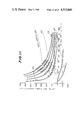
- FIG. 3 is a graph showing engine performance curves
- FIG. 4 is a graph showing a target engine revolution speed curve and a target throttle opening degree curve
- FIG. 5 is a graph showing two different electric signals generated by a limit engine revolution speed function generator circuit
- FIG. 6 is a cross sectional view showing a first form of a line pressure regulator valve used in the control apparatus shown in FIG. 1;
- FIG. 7 is a cross sectional view of a shift control valve
- FIG. 8 is a graph showing how oil pressure within a drive pulley cylinder chamber and that within a driven pulley cylinder chamber vary against an increase or decrease in an electric current passing through a solenoid of the shift control valve from a reference electric current (I CHO );
- FIG. 9 is a circuit diagram showing a second form of a shift control valve driver
- FIG. 10 is reduction ratio vs., vehicle speed characteristic for different combinations of accelerator pedal stroke (Acc) with engine revolution speed (Nn);
- FIG. 11 is a graph showing driving force vs., vehicle speed characteristic for different accelerator pedal strokes (Acc) corresponding to engine horsepower outputs, and running resistance vs., vehicle speed characteristic for different road gradients;
- FIG. 12 is a circuit diagram showing a second form of a shift control valve driver
- FIG. 13 is graph showing an electric current vs., reduction ratio characteristic generated by a line pressure function generator circuit
- FIG. 14 is a graph showing a line pressure characteristic provided by a line pressure control device including the line pressure regulator valve shown in FIG. 7;
- FIG. 15 is a schematic view showing a drive pulley, a driven pulley and a V-belt running around both pulleys;
- FIG. 16 is a graph showing the form of a function f(ic) which is used as a coefficient in a required oil pressure computing equation
- FIG. 17 is a graph showing the relationship between engine torque and intake manifold vacuum
- FIG. 18 is a graph showing a desired line pressure characteristic
- FIG. 19 is a second form of a line pressure control device
- FIG. 20 is a longitudinal sectional view of a vacuum sensor used in the electronic control device shown in FIG. 2A and in the line pressure control device shown in FIG. 19;
- FIG. 21 is a longitudinal sectional view of a second form of a line pressure regulator valve used in the line pressure control device shown in FIG. 19;
- FIG. 22 is a diagrammatic sectional view showing a third form of a line pressure control device
- FIG. 23 is a graph showing the relationship between a force applied to one end of a lever of the line pressure control device shown in FIG. 21 and intake manifold vacuum;
- FIG. 24 is a graph showing how a force applied to the other end of the lever and a line pressure vary vs., intake manifold vacuum.
- FIG. 1 illustrates diagrammatically a control apparatus according to the present invention.
- An intake pipe 4 of an engine 2 has mounted thereon a carburetor 6, and the opening degree of a throttle valve 8 of the carburetor 6, serving as a fuel supply device for controlling the supply of fuel to the intake pipe 4, is adjustable by a throttle valve actuator 10 (which actuator operates in response to an electric signal 106 from a later described electronic control device 100).
- the fuel supply device is in the form of a carburetor and its throttle valve being controlled, in the case of a diesel engine having no throttle valve, a fuel injection pump serves as the fuel supply device and directly controls the fuel supply.
- the throttle valve 8 is pulled by the throttle valve actuator 10 via a wire 14 having a stop 12 against a return spring 16.
- a stroke of an accelerator pedal 18 is transmitted via a link mechanism 20 to a lever 22.
- a lever 22 Coupled with the lever 22 is a movable portion of an accelerator pedal sensor 24 which serves as a converter converting a displacement to an electric signal, thus allowing the issuance of an electric signal 26 indicative of the stroke of the accelerator pedal 18.
- the electric signal 26 from the accelerator pedal sensor 24 is sent to the electronic control device 100 which is described later.
- the lever 22 is connected with a safety throttle valve 32 by a spring 28 and a wire 30, the wire 30 passing through a stationary portion 34 and having a stop 36.
- the arrangement is such that when the accelerator pedal 18 is depressed by 10% of its full stroke the stop 36 comes into contact with the stationary portion 34 and the opening degree of the safety throttle valve 32 becomes and remains 100% as long as this state exists (the state where the stop 36 is in contact with the stationary portion 34). Accordingly, during the subsequent stroke (10% to 100%) of the accelerator pedal 18, the spring 28 extends under axial tension, allowing the safety throttle valve 32 to remain in the open state.
- the safety throttle valve 32 is subject to bias force by a return spring 38 tending to close the valve.
- Mounted on the revolution shaft 2a of the engine 2 is a revolution speed sensor 40 which supplies an electric signal 42 to the electronic control device 100. The revolution of the engine 2 is fed to a continuously variable V-belt transmission 50.
- the continuously variable V-belt transmission 50 includes a centrifugal clutch 52, a drive pulley 54, a driven pulley 56, and a final drive 58.
- the centrifugal clutch 52 begins to transmit the revolution of the engine 2 to the drive pulley 54 through the drive shaft 60.
- the drive pulley 54 includes an axially fixed conical disc fixed to the drive shaft 60 and an axially movable conical disc 66 which is arranged to face the fixed conical disc 62 to define a V-shaped pulley groove and is movable aixally along the drive shaft 60 under the influence of oil pressure acting within a drive pulley cylinder chamber 64.
- the drive pulley 54 is drivingly connected to a driven pulley 56 by a V-belt 68
- the driven pulley 56 includes an axially fixed conical disc 72 fixed to a driven shaft 70 and an axially movable conical disc 76 which is arranged to face the fixed conical disc 72 to define a V-shaped pulley groove and is movable axially along the driven shaft 70 under the influence of oil pressure acting within a driven pulley cylinder chamber 74.
- the ratio of revolution of the drive pulley 54 to that of the driven pulley 56 may be varied by axially displacing the movable conical disc 66 of the drive pulley 54 and the movable conical disc 76 of the driven pulley 56 so as to vary the radius of the contacting curvature of each of the pulleys with the V-belt 68.
- the width of the V-shaped pulley of the drive pulley 54 is decreased, the radius of the contacting curvature of the drive pulley 54 with the V-belt 68 decreases and the radius of the contacting curvature of the driven pulley 56 with the V-belt increases, thus providing a larger reduction ratio. If the movable conical discs 66 and 76 are displaced inversely to the above case, the reduction ratio becomes small.
- the driven shaft 70 is connected to output shafts 82 and 84 by reduction gears 78 and 80 of the final drive 58.
- the driven shaft 70 has mounted thereon a vehicle speed sensor 86 which detects revolution speed of the driven shaft 70 (which corresponds to vehicle speed).
- the vehicle speed sensor 86 generates an electric signal 88 indicative of the vehicle speed and supplies it to the electronic control device 100.
- the before mentioned cylinder chamber 64 of the drive pulley 54 and cylinder chamber 74 of the driven pulley 56 are connected to a shift control valve 92 of an oil pressure control device 90 through passage 91 and 93.
- the operation of the shift control valve 92 is controlled in response to an electric signal 102 from the electronic control device 100.
- the line pressure supplied to the shift control valve 92 from an oil pump 94 is regulated by the line pressure regulator valve 96.
- the line pressure regulator valve 96 is controlled in response to an electric signal 104 from the electronic control device 100.
- the line pressure regulator valve 96 is supplied as a source of power with a vacuum within the intake pipe 4 via a conduit 98.
- the practical construction of the shift control valve 92 and that of the line pressure regulator valve 96 are explained later.
- the electronic control device 100 receives electric signals 26, 42 and 88 from the accelerator pedal 24, engine revolution speed sensor 40 and vehicle speed sensor 86, and based on these electric signals the electronic control device 100 supplies electric signals 106, 102 and 104 to the throttle valve actuator 10, shift control valve 92 and line pressure regulator valve 96, respectively, to control their operations. Next, the construction of this electronic control device 100 is explained.
- FIG. 2 illustrates a block diagram of the electronic control device 100.
- the electric signal 26 from the above mentioned accelerator pedal sensor 24 is fed to an engine revolution speed function generator circuit 108 of the electronic control device 100 and to a throttle valve opening degree function generator circuit 110 thereof, in each of which a conversion is made using a predetermined function to produce, as an output signal, a target engine revolution speed electric signal 112 in the former case or a target throttle valve opening degree electric signal 114 in the latter case.
- the above-mentioned functions used in the function generator circuits 108 and 110 are determined as follows.
- FIG. 3 shows performance curves of the engine 2.
- the abscissa axis shows engine revolution speed and the ordinate axis, on the lefthand side an engine output horsepower output, a plurality of dotted line curves show engine horsepower output versus engine revolution speed for different throttle valve opening degrees (15°, 25°, 35°, 45°, 55°, 65°, and fully opened).
- Fine fully drawn curves are iso-fuel consumption rate curves (300, 240, 220, 210, 200 g/ps h). From these iso-fuel consumption rate curves for different engine horsepower output, an operation point is selected wherein the engine operates at the least fuel consumption rate, and such points are interconnected to provide a bold fully drawn curve 116.
- This curve 116 is called the minimum fuel consumption rate curve, and if the engine 2 is operated on this curve 116, the engine operates at the least fuel consumption rate.
- the ordinate axis on the righthand side shows accelerator pedal stroke wherein the accelerator pedal stroke 100% corresponds to the maximum engine horsepower output (84 ps) and the accelerator pedal stroke 0% corresponds to horsepower output 0 (zero).
- the accelerator pedal stroke does not mean the actual opening degree of the throttle valve 8 and indicates no more than the stroke of the accelerator pedal 18, meaning how much the driver demands engine horsepower output. For example, an accelerator pedal stroke 60% indicates the intention of the driver that he demands 60% of the maximum horsepower output of the engine for driving the vehicle.
- the engine revolution speed function generator circuit 108 and throttle valve opening degree function generator circuit 110 generates 6.0 V and 7.2 V as output signals thereof, respectively, when the accelerator pedal stroke is 60%.
- the function generator circuits 108 and 110 which convert the electric signal (electric voltage) from the accelerator pedal sensor 24 along the predetermined functions shown in FIG.
- the curve 116 (the iso-fuel consumption rate curve) rises vertically at 1200 rpm because, when the engine rotates below this engine rpm, the vibration of the engine torque exceeds an allowable vibration limit and the use of the engine below this engine rpm is not practical.
- the actual iso-fuel consumption rate curve extends below 1200 rpm, emphasis is placed on prevention of vibration rather than reduction of fuel consumption rate within this operating range in controlling the engine.
- a L1 position i.e., a position wherein the transmission is locked in a predetermined reduction ratio for weak engine braking
- an electric signal 142 indicating that the shift lever 138 is set to a L2 position (i.e., a position wherein the transmission is locked in another predetermined reduction ratio for strong engine braking) or to a R position (reverse position).
- a reduction ratio arithmetic operation circuit 152 are the actual engine revolution speed electric signal 42 from the engine revolution speed sensor 40 and the vehicle speed electric signal 88 from the vehicle speed sensor 86 so as to perform arithmetic operation to provide a current reduction ratio of the continuously variable transmission 50.
- the reduction ratio provided by the arithmetic operation is fed in the form of an electric signal 154 to the line pressure generator circuit 156.
- the line pressure function generator circuit 156 converts this electric signal using a predetermined function and then supplies the thus converted electric signal 158 to the line pressure regulator valve driver 160.
- the line pressure regulator valve driver 160 suppies an electric command signal 104 to the line pressure regulator valve 96 to drive same.
- the line pressure should be set such that it increases with increasing reduction ratio and with increasing output torque of the engine (with decreasing intake manifold vacuum). This has been accomplished by the line pressure function generator circuit 156 which converts the electric signal 154 into the electric signal 158 indicative of an oil pressure determined depending upon the reduction ratio. Further explanation of this is made later. With the conduit 98 (see FIG. 1) the intake manifold vacuum is introduced to the line pressure regulator valve 96. Thus, the line pressure is controlled to vary depending upon the intake manifold vacuum, too.
- a chamber 182 disposed on the righthand side of the small diameter portion 178b of the spool communicates with a passage forming part of a line pressure circuit, and a port 184 mating with the large diameter portion 178a communicates with the passage 172.
- a chamber 186 defined between the large diameter portion 178a of the spool 178 and small diameter portion 178b of the spool 178 is drained via a drain passage 188.
- a vacuum chamber 192 defined by a diahragm 190 is arranged on the lefthand side of the spool 178, which vacuum chamber 192 communicates with the intake pipe 4 of the engine via the before mentioned conduit 98.
- a push rod 194 attached to the diaphragm 190 is biased by a spring 196 into contact with the left end of the spool 178.
- a solenoid 198 which has a push rod 200 thereof extending through the hollow portion of the push rod 194 and in contact with the left end of the spool 178 under the action of a spring 202.
- the spool 178 is subjected to a leftwardly directed force by the line pressure within the chamber 182 applied to push the small diameter portion 178b of the spool and a rightwardly directed force by the spring 180, by the push rod 194 and by the push rod 200, and the opening degree of the port 184 is regulated to a degree wherein the both opposed forces are balanced, thus regulating the pressure in the passage 172.
- the oil pressure within the passage 172 i.e., the line pressure, therefore increases with increase in the pushing forces by the push rods 194 and 200. Since the pushing force by the push rod 194 decreases with increase in the vacuum in the vacuum chamber 192, the line pressure is inversely proportional to the intake manifold vacuum in the intake pipe 4.
- the line pressure is inversely proportional to the electric current force through the solenoid 198.
- the electric command signal 104 is in the form of an electric current passing through the solenoid 198. This electric current varies in such a manner as to cause the line pressure to increase with increase in reduction ratio. Therefore, the line pressure is controlled to increase with increasing output torque of the engine and with increasing reduction ratio.
- the shift control valve 92 to be supplied with the thus regulated line pressure generated by the above mentioned line pressure regulator valve 96 is explained specifically in connection with FIG. 7.
- a spool 208 having three same diameter lands 208a, 208b and 208c.
- the valve bore 206 has seven ports 210, 212, 214, 216, 218, 220 and 222, wherein the left and right edge ports 210 and 222 and the center port 216 are drained toward the tank 170.
- the port 212 communicates with the port 220 and they are supplied with the line pressure.
- the port 214 communicates via the passage 91 with the before mentioned drive pulley cylinder chamber 64, and the port 218 communicates via the passage 93 with the before mentioned driven pulley cylinder chamber 74.
- the ports 212 and 220 are arranged such that when the center land 208 assumes a position wherein it agrees with the port 216, the ports 212 and 220 are uncovered by the lands 208a and 208c respectively, forming clearances communicating with the ports 214 and 218, respectively. Therefore, moving the spool rightwardly from this middle position results in a reduction in oil pressure in the port 214 and an increase in oil pressure in the port 218.
- valve bores 228 and 230 receiving a spool 232 with a land 232a and a spool 234 with a land 234a, respectively, with their rods 232b and 234b contacting with both ends of the spool 208, respectively.
- a chamber 236 defined on the lefthand side of the valve bore 230 by the spool 234 communicates with the passage 172, and the chamber 238 on the righthand side communicates with the passage 93.
- the spool 234 is biased leftwardly by a spring 240.
- the spool 232 is arranged to be biased rightwardly by the push rod 246a of the solenoid 246.
- This movement of the spool 208 causes the land 208b to form a clearance opening into the drain port 216, causing a reduction in oil pressure in the port 214. Since the port 214 communicates with the lefthand side chamber 244 of the spool 232, oil pressure within the lefthand side chamber 244 also reduces. Since the line pressure is always supplied to the righthand side chamber 242 of the spool 232, the spool 232 is subjected to a leftwardly directed force which is proportional to the reduction in oil pressure within the chamber 244. This leftwardly directed force balances with the increased amount of electric current passing through the solenoid 246.
- FIG. 8 shows how the oil pressure varies with the above mentioned change in electric current passing through the solenoid 246. In the above manner, the reduction ratio is varied only by controlling the electric current passing through solenoid 246.
- the shift control valve driver 150 is an electric circuit constructed by interconnecting an OP amplifier 250, an inversion amplifiers 252 and 254, each having a gain 1, a transistor 256, resistors R1, R2, R3 and R4, and a potentiometer 258.
- an electric signal 148 i.e., a deviation (V N -V R ) between the electric voltage V N indicative of the target engine revolution speed and the electric voltage V R indicative of the actual engine revolution speed
- the potentiometer 258 is so adjusted that an electric voltage e CHO appears on the signal line 262. If, in this circuit, the electric current passing through the solenoid 246 is set as I CH , the relation is defined by the following equation. ##EQU1## From this equation we have, ##EQU2##
- V N -V R >0 (i.e., in the case the target engine revolution speed is greater than the actual engine revolution speed)
- I CH >I CHO holds, resulting in an increase in the pushing force of the solenoid 246, causing a decrease in the oil pressure within the drive pulley cylinder chamber 64 as shown in FIG. 8, thus allowing the reduction ratio to become large to decrease the deviation (V N -V R ) finally into zero.
- V N -V R ⁇ 0 the oil pressure within the driven pulley cylinder chamber 74 decreases to allow the reduction ratio to become small.
- the continuously variable transmission is controlled in such a manner as to decrease the deviation V N -V R , i.e., to maintain the actual engine revolution speed as being equal to the target engine revolution speed.
- the electric signal 26 from the accelerator pedal sensor 24 is converted by the engine revolution speed function genrator circuit 108 to the electric signal 112 which indicates an engine revolution speed of 3370 rpm.
- the electric signal 112 is red to the switching circuit 126, but, since the shift lever 138 is set to the D position, it is issued as an electric signal 146 therefrom and compared at the comparator circuit 144 with the actual engine revolution speed electric signal 42 from the engine revolution speed sensor 40 to provide the deviation which is sent out in the form of electric signal 148 to the shift control valve driver 150, causing the shift control valve driver 150 to operate the shift control valve 92 in such a manner as to decrease the deviation.
- a curve 284 interconnecting the lower limit values for different accelerator pedal strokes and a curve 286 interconnecting the upper limit values for different acclerator pedal strokes define therebetween an operating range within which the vehicle is allowed to operate on the minimum fuel consumption rate curve. From comparison of this controllable range with the running resistance due to the gradient of a road, it will be understood that it can be controlled under most of the running conditions.
- the shift lever 138 is moved to the L1 position, the engine is controlled to maintain an engine revolution speed of 5600 rpm, thus preventing the engine from overrunning. Since the engine revolution speed of 1000 rpm is maintained when the vehicle is running at a speed below 15 Km/h, the reduction ratio larger than 1.75 is maintained when the vehicle is started from the standstill with the shift lever 138 set to L1 position, allowing the vehicle to start smoothly even when the L1 position is selected.
- the safety throttle valve 32 As mentioned before, since the throttle valve 8 is controlled by the throttle valve actuator 10, there would happen a dangerous case that the throttle valve is opened against the intention of the driver if the electronic control device 100 and/or throttle valve actuator 10 become out of order. The occurrence of this dangerous case could be avoided by manipulating the accelerator pedal to maintain the accelerator pedal stroke as 0% to close the safety throttle valve 32 to provide an ordinary idle state. Besides, in this case, the vehicle can be kept running for emergency by controlling the opening degree of the safety throttle valve 32 by manipulating the accelerator pedal 18. Since the safety throttle valve 32 is designed to be fully opened when the accelerator pedal 18 is depressed to the stroke of 10% of the full stroke, the engine is controlled in the ordinary state by the opening degree of the throttle valve 8 as long as the accelerator pedal 18 is operated beyond the stroke of 10%.
- the shift control valve driver 150 used in the embodiment thus far described may be replaced with a shift control valve driver 300 as shown in FIG. 12.
- This shift control valve driver 300 is different from the shift control valve driver 150 in the addition of a differentiator circuit 302 and an integrator circuit 304.
- a circuit 150' is substantially the same as the shift control valve driver 150, and the circuit 150' is fed with the electric signal 148 (deviation V N -V R ), an electric signal 306 resulting from differentiating the electric signal 148, and an electric signal 308 resulting from integrating the electric signal 148 with suitable weights thereon, respectively, after they are added to each other.
- this shift control valve 300 of this construction is the same as that of the before mentioned shift control valve driver 150 in the static state, but the differentiator circuit 302 provides an additional effect as follows: If the accelerator pedal 18 is depressed rapidly, the electric signal 148 changes quickly as compared to the case wherein the accelerator pedal 18 is depressed slowly, causing the electric signal 306 generated by the differentiator circuit 302 to increases. Therefore, the greater amount of the electric signal is fed to the circuit 150', thus increasing the electric current flowing through the solenoid 246 accordingly, causing the shift control valve 92 to respond quickly to the change in the reduction ratio. It follows that the operation state of the engine follows closely to the manipulation of the accelerator pedal by the driver, thus enhancing the driveability of the vehicle.
- the integrator circuit 304 provides an effect as follows: If, owing to an error in the shift control valve 92 and an error in oil pressure acting within the pulley cylinder chambers 64 and 74, there remains a steady-state deviation in the electric signal 148 (deviation V N -V R ) which is relatively small in amount, the integrator circuit 304 accumulates the remained steady-state deviation and sends out as the result in the form of electric signal 308 to the circuit 150', causing the solenoid 246 to operate in such a manner as to reduce the steady-state deviation. It follows that the more accurate control is carried out, thus making it possible to operate the engine on the minimum fuel consumption rate curve, i.e., target of the control.
- a throttle valve opening degree is used as a target value and the throttle valve 8 of the carburetor 6 is adjusted to the target throttle valve opening degree indicated by the electric signal 114 generated by the throttle valve opening degree function generator circuit 110, it is possible to use an intake manifold vacuum as the target value and to adjust the throttle valve 8 in such a manner as to decrease a deviation between an actual intake manifold vacuum and a target intake manifold vacuum.
- a function generator circuit 110A which is similar to the function generator circuit 110, generates an electric signal 114A indicative of a target intake manifold vacuum as a predetermined function of a depression degree of an accelerator pedal 18 indicated by the accelerator pedal stroke electric signal 26.
- a vacuum sensor 404 detects intake manifold vacuum within an intake pipe 4 and generates an electric signal 406 indicative of the actual intake manifold vacuum.
- the electric signal 114A indicative of the actual intake manifold vacuum and the electric signal 114A indicative of the target intake manifold vacuum are compared with each other at a comparator circuit 500.
- the comparator circuit 500 generates an electric signal 502 indicative of the deviation between the both signals 114A and 406.
- a throttle valve actuator driver 504 supplies a command electric signal to a throttle valve actuator 10 to increase the opening degree of the throttle valve 8 when the actual intake manifold vacuum is larger than the target intake manifold vacuum and closes same when the actual intake manifold vacuum is smaller than the target intake manifold vacuum.
- the use of the throttle valve opening degree or intake manifold vacuum as the target value is suitable for a gasoline internal combustion engine but not suitable for a diesel engine which is not provided with a throttle valve.
- the invention is however applicable to the diesel engine if a position of a control lever of a fuel injection pump is used as the target value.
- a function generator circuit 110B generates an electric signal 114B indicative of a target control lever position as a predetermined function of an accelerator pedal stroke electric signal 26.
- a control lever actuator driver 510 generates a command electric signal 512 in response to the electric signal 114B indicative of the target control lever position and supplies it to a control lever actuator 514 which is mechanically connected to a control lever 516 of a fuel injection pump 518 which is known as a distributor-type fuel injection pump type VE.
- Fuel within a fuel tank 520 is delivered by a presupply pump 522 to the inside of the pump housing of the fuel injection pump 518 via a fine filter 524.
- the delivered fuel is metered within the fuel injection pump in a known manner and then injected to the engine cylinders by nozzles 526.
- the line pressure function generator circuit 156 effects conversion of the electric signal 154 from the reduction ratio arithmetic operation circuit 152 using a predetermined function to produce the result in the form of an electric signal 158, the form of the function being illustrated in FIG. 13.
- the current I varies from the value of 7.26 A to the value of 0 A linearly with variation in the reduction ratio ic from 0.5 to 3.5. This relation is expressed by
- V E . . . intake manifold vacuum Kg/cm 2
- FIG. 15 shows in diagram a drive pulley 54, a driven pulley 56 and a V-belt 68.
- the radius of contacting diameter of the V-belt with the drive pulley is r 1
- the radius of contacting diameter of the V-belt with the driven belt 56 is r 2
- the distance between the shafts of the both pulleys is L
- the length of the V-belt is l
- the reduction ratio is i c
- T 1 is a torque of the shaft of the drive pulley and is equal to the output shaft torque of the engine 2.
- FIG. 17 illustrates how the engine torque varies versus engine intake manifold vacuum (V E ) and this relation can be defined by
- the line pressure characteristic provided by the above mentioned line pressure regulator valve 96 resembles subatantially the ideal line pressure characteristic, but, strictly speaking the line pressure becomes higher than the ideal line pressure when the vacuum falls in a high vacuum range (see FIGS. 18 and 14). With the second form which is described hereinafter in connection with FIG. 19, the line pressure characteristic is obtained which agrees strictly with the ideal line pressure characteristic.
- Arithmetic operation circuit 402 that computes the required oil pressure is supplied with an electric signal 154 from the reduction ratio arithmetic operation circuit 152 indicative of a reduction ratio and also an electric signal 406 from a vacuum sensor 404 indicative of a vacuum pressure.
- This reduction ratio arithmetic operation circuit 152 is the same as the reduction ratio arithmetic operation circuit 152 shown in FIG. 2.
- the vacuum sensor 404 includes a vacuum chamber 410 defined by a diaphragm 408, the vacuum chamber being connected with an engine intake pipe 4, a rod 412 attached to the diaphragm 408 being pressed rightwardly by a spring 414. Attached to the rod 412 is a potentiometer 416. It follows that the rod 412 moves in proportional to the intake manifold vacuum, thus causing the potentiometer 416 to produce an electric signal 406 proportional to the intake manifold vacuum. In the required oil pressure arithmetic operation circuit.
- the line pressure regulator valve 422 has a construction resulting from removing the diaphragm 190 from the line pressure regulator valve 96 shown in FIG. 7 (the same reference numerals as used in FIG. 7, thus omitting the detailed description). Consequently, with the line pressure regulator valve 422, the line pressure varying in proportional to the electric current passing through the solenoid 198 is provided. Accordingly, the ideal line pressure characteristic as shown in FIG. 18 is obtained.
- valve bore 452 of a line pressure regulator valve 451 formed in a valve body 450 and a spool 454 is similar to that between counterparts in FIG. 6 such that there occurs in a passage 172 an oil pressure varying in proportional to a force F2 applied upwardly, viewing in the Figure, to the spool 454.
- the lower end of the spool 454 is linked with one end of a lever 456 which has an other end thereof being attached to a rod 460 attached to the diaphragm 458 and being pressed by a spring 462. It follows that applied to the other end of the lever 456 is a force F1 obtained by adding a force by a spring 456 to a constant force by the spring 462.
- the vacuum chamber 464 above the diaphragm 458 communicates with the engine intake manifold and is dimensioned such that a force applied to the diaphragm 458 when the vacuum is 350 mmHg is equal to a force of the spring 468. Therefore, there is applied no force on the rod 460 when the vacuum is not smaller than 350 mmHg and there is applied to the latter a force inversely proportional to the vacuum when the vacuum is smaller than 350 mmHg. Therefore, the force F1 reveals the relation as shown in FIG. 22.
- a movable fulcrum which is constructed of a roller 472 attached to one end of a rod 470 that is movable to right and left viewing in the Figure.
- the rod 470 at an other end thereof is pressed against the conical disc 66 of the driving pulley 54 by means of a spring 474.
- F1 shows a characteristic as shown in FIG. 22 as previously described
- F2 shows a characteristic as shown in FIG. 23 for different values of l 1 /l 2 .
- the line pressure in the passage 172 varies in proportional to F 2
- the line pressure shows the characteristic as shown in FIG. 24.
- This line pressure characteristic agrees with the ideal line pressure characteristic as shown in FIG. 17 previously described. In this manner, in this embodiment the desired line pressure is obtained without use of an electronic circuit.
- a potentiometer 476 is mounted on the rod 470 as shown in FIG. 22, an output signal therefrom indicates a reduction ratio, thus providing the reduction ration in terms of an electric signal. It makes no difference even if the rod 470 is render to coact with the movable conical disc 76 of the driven pulley 56.
- the line pressure that is a shift control operating pressure to be supplied to the shift control valve is adjusted to vary in proportional to the reduction ratio between the drive and driven pulleys and in inreverse proportional to the intake manifold vacuum, so that the line pressure is adjusted to provide a succificntly high V-belt transmission torque capacity in accordance with the engine output torque and reduction ratio, thus allowing the V-belt to always subject to an appropriate force, enhancing its life and the power transmission effeciency.
- the line pressure characteristic is provided without any use of an electronic control circuit, thus making contribution to reduction in cost.
Landscapes
- Engineering & Computer Science (AREA)
- Chemical & Material Sciences (AREA)
- Combustion & Propulsion (AREA)
- Mechanical Engineering (AREA)
- Transportation (AREA)
- General Engineering & Computer Science (AREA)
- Automation & Control Theory (AREA)
- Control Of Transmission Device (AREA)
- Control Of Driving Devices And Active Controlling Of Vehicle (AREA)
Applications Claiming Priority (6)
| Application Number | Priority Date | Filing Date | Title |
|---|---|---|---|
| JP13332781A JPS5835240A (ja) | 1981-08-27 | 1981-08-27 | エンジンの燃料供給装置制御機構 |
| JP56-133327 | 1981-08-27 | ||
| JP56137826A JPS5839870A (ja) | 1981-09-03 | 1981-09-03 | エンジン・無段変速機駆動系統の制御装置 |
| JP56137827A JPS5839871A (ja) | 1981-09-03 | 1981-09-03 | Vベルト式無段変速機のライン圧制御装置 |
| JP56-137827 | 1981-09-03 | ||
| JP56-137826 | 1981-09-03 |
Publications (1)
| Publication Number | Publication Date |
|---|---|
| US4515040A true US4515040A (en) | 1985-05-07 |
Family
ID=27316671
Family Applications (1)
| Application Number | Title | Priority Date | Filing Date |
|---|---|---|---|
| US06/411,987 Expired - Lifetime US4515040A (en) | 1981-08-27 | 1982-08-26 | Control apparatus and method for engine-continuously variable transmission |
Country Status (3)
| Country | Link |
|---|---|
| US (1) | US4515040A (de) |
| EP (1) | EP0073475B1 (de) |
| DE (1) | DE3278072D1 (de) |
Cited By (112)
| Publication number | Priority date | Publication date | Assignee | Title |
|---|---|---|---|---|
| US4569254A (en) * | 1983-05-23 | 1986-02-11 | Toyota Jidosha Kabushiki Kaisha | Method for controlling an engine installed with continuously variable transmission |
| US4589302A (en) * | 1983-04-26 | 1986-05-20 | Mazda Motor Corporation | Control system for an automotive driving system including an engine throttle valve and a stepless transmission |
| US4612828A (en) * | 1984-04-20 | 1986-09-23 | Fuji Jukogyo Kabushiki Kaisha | Control system for an infinitely variable transmission |
| US4622865A (en) * | 1983-07-13 | 1986-11-18 | Toyota Jidosha Kabushiki Kaisha | Apparatus for controlling continuously variable transmission when accelerating from low speeds |
| US4622867A (en) * | 1983-03-14 | 1986-11-18 | Nissan Motor Co., Ltd. | Method of controlling ratio change in continuously variable transmission |
| US4637280A (en) * | 1984-08-03 | 1987-01-20 | Nissan Motor Co., Ltd. | Control system for motor vehicle with continuously variable transmission and engine |
| US4641553A (en) * | 1984-09-13 | 1987-02-10 | Aisin Seiki Kabushiki Kaisha | Control system and method for a power delivery system having a continuously variable ratio transmission |
| US4649487A (en) * | 1983-06-06 | 1987-03-10 | Toyota Jidosha Kabushiki Kaisha | Method and apparatus for controlling continuously variable transmission for vehicle |
| US4649485A (en) * | 1983-08-22 | 1987-03-10 | Toyota Jidosha Kabushiki Kaisha | Apparatus for controlling continuously variable transmission |
| US4649488A (en) * | 1983-06-06 | 1987-03-10 | Toyota Jidosha Kabushiki Kaisha | Method and apparatus for controlling continuously variable transmission for vehicle |
| US4653006A (en) * | 1983-09-01 | 1987-03-24 | Toyota Jidosha Kabushiki Kaisha | Method and apparatus for controlling continuously variable transmission for vehicle |
| US4653004A (en) * | 1983-08-22 | 1987-03-24 | Toyota Jidosha Kabushiki Kaisha | Method and apparatus for controlling continuously variable transmission for vehicle |
| US4653005A (en) * | 1983-09-01 | 1987-03-24 | Toyota Jidosha Kabushiki Kaisha | Method and apparatus for controlling continuously variable transmission for vehicle |
| US4651595A (en) * | 1983-08-31 | 1987-03-24 | Fuji Jukogyo Kabushiki Kaisha | Kickdown system for an infinitely variable transmission |
| US4656587A (en) * | 1983-08-22 | 1987-04-07 | Toyota Jidosha Kabushiki Kaisha | Apparatus for controlling continuously variable transmission |
| US4658360A (en) * | 1983-09-01 | 1987-04-14 | Toyota Jidosha Kabushiki Kaisha | Method and apparatus for controlling continuously variable transmission for vehicle |
| US4663990A (en) * | 1983-05-23 | 1987-05-12 | Toyota Jidosha Kabushiki Kaisha | Method for controlling continuously variable transmission |
| US4672864A (en) * | 1984-11-16 | 1987-06-16 | Fuji Jukogyo Kabushiki Kaisha | Control system for an infinitely variable transmission |
| US4680987A (en) * | 1984-11-16 | 1987-07-21 | Fuji Jukogyo Kabushiki Kaisha | Control system for an infinitely variable transmission |
| US4685357A (en) * | 1984-11-30 | 1987-08-11 | Toyota Jidosha Kabushiki Kaisha | Continuously variable transmission hydraulic control system having two pressure regulating valves |
| US4686871A (en) * | 1983-09-30 | 1987-08-18 | Aisin Seiki Kabushiki Kaisha | Power delivery system having a continuously variable ratio transmission |
| US4689745A (en) * | 1984-07-18 | 1987-08-25 | Toyota Jidosha Kabushiki Kaisha | Apparatus for controlling continuously variable transmission used in vehicle |
| US4700590A (en) * | 1985-09-30 | 1987-10-20 | Aisin Seiki Kabushiki Kaisha | System for utilizing the negative torque of a power delivery system having a continuously variable ratio transmission for braking |
| US4702128A (en) * | 1984-05-14 | 1987-10-27 | Nissan Motor Co., Ltd. | Ratio control system for continuously variable transmission |
| US4703428A (en) * | 1983-12-14 | 1987-10-27 | Nissan Motor Co., Ltd. | Power train control method on common input data |
| US4715258A (en) * | 1983-08-29 | 1987-12-29 | Toyota Jidosha Kabushiki Kaisha | Power transmission for use in automobiles having continuously variable transmission |
| US4718012A (en) * | 1984-05-23 | 1988-01-05 | Nissan Motor Co., Ltd. | Control system for drive train including continuously variable transmission |
| US4720793A (en) * | 1984-09-25 | 1988-01-19 | Toyota Jidosha Kabushiki Kaisha | Method and apparatus for controlling drive force of a vehicle equipped with continuously variable transmission |
| US4729103A (en) * | 1983-10-18 | 1988-03-01 | Nissan Motor Co., Ltd. | Control device for continuously variable transmission |
| US4727771A (en) * | 1983-05-09 | 1988-03-01 | Toyota Jidosha Kabushiki Kaisha | Method for controllig a controlling a continuously variable transmission |
| US4735112A (en) * | 1983-08-22 | 1988-04-05 | Toyota Jidosha Kabushiki Kaisha | Apparatus for controlling continuously variable transmission |
| US4737915A (en) * | 1983-12-06 | 1988-04-12 | Nissan Motor Co., Ltd. | Power train control method |
| US4750598A (en) * | 1985-06-12 | 1988-06-14 | Mitsubishi Jidosha Kogyo Kabushiki Kaisha | Control system for the throttle valve of a vehicle engine |
| US4771658A (en) * | 1985-08-30 | 1988-09-20 | Fuji Jukogyo Kabushiki Kaisha | System for controlling the pressure of oil in a system for a continuously variable transmission |
| US4796489A (en) * | 1983-10-29 | 1989-01-10 | Mazda Motor Corporation | Speed ratio control for a step-lessly variable vehicle transmission |
| US4817469A (en) * | 1983-08-22 | 1989-04-04 | Toyota Jidosha Kabushiki Kaisha | Automatic transmission for automobile and method of controlling same |
| US4819513A (en) * | 1986-03-31 | 1989-04-11 | Fuji Jukogyo Kabushiki Kaisha | Transmission ratio control system for a continuously variable transmission |
| US4852429A (en) * | 1986-10-25 | 1989-08-01 | Daimler-Benz Aktiengessellschaft | Method and apparatus for controlling the steplessly variable transmission ratio of a continuously variable transmission, especially of a cone disk belt transmission, in a motor vehicle |
| US4853857A (en) * | 1986-07-01 | 1989-08-01 | Nissan Motor Company, Ltd. | Ratio control for continuously variable transmission |
| US4893526A (en) * | 1986-09-19 | 1990-01-16 | Toyota Jidosha Kabushiki Kaisha | Continuous variable transmission control system |
| US4905785A (en) * | 1987-12-24 | 1990-03-06 | Paccar Inc | Intermediate governor system |
| US4942783A (en) * | 1986-08-23 | 1990-07-24 | Fuji Jukogyo Kabushiki Kaisha | Transmission ration control system for a continuously variable transmission |
| US4961315A (en) * | 1987-10-12 | 1990-10-09 | Honda Giken Kogyo Kabushiki Kaisha | Method of controlling speed reduction ratio of continuously variable speed transmission |
| US5025685A (en) * | 1988-07-29 | 1991-06-25 | Honda Giken Kogyo Kabushiki Kaisha | Controlling device for non-stage transmission for vehicles |
| US5040114A (en) * | 1988-07-20 | 1991-08-13 | Honda Giken Kogyo Kabushiki Kaisha | Method of controlling continuously variable transmission in combination with engine throttle control |
| US5042324A (en) * | 1989-08-03 | 1991-08-27 | Nissan Motor Co., Ltd. | Control of torque generated by engine followed by continuously variable transmission |
| US5042325A (en) * | 1989-07-06 | 1991-08-27 | Mazda Motor Corporation | Control system for steplessly variable power transmission |
| US5056482A (en) * | 1989-12-01 | 1991-10-15 | Fuji Heavy Industries Ltd. | Engine protecting system |
| US5101687A (en) * | 1989-11-16 | 1992-04-07 | Toyota Jidosha Kabushiki Kaisha | Shift control system and method using a main throttle and a sub throttle valve for torque control for automatic transmissions |
| US5166877A (en) * | 1987-10-02 | 1992-11-24 | Honda Giken Kogyo Kabushiki Kaisha | Method of speed reduction ratio control in continuously variable speed transmission |
| US5173084A (en) * | 1991-12-23 | 1992-12-22 | Ford Motor Company | Self-clamping assist for "V" belt continuously variable transmissions |
| US5214983A (en) * | 1988-07-29 | 1993-06-01 | Honda Giken Kogyo Kabushiki Kaisha | Controlling device for non-stage transmission for vehicle with fault detection |
| US5305662A (en) * | 1991-04-19 | 1994-04-26 | Mitsubishi Jidosha Kogyo Kabushiki Kaisha | Drive by wire control device for an internal combustion engine and a continuous variable transmission using engine torque correction means based on acceleration to determine a rate-of-change of speed-ratio correction means |
| US5355749A (en) * | 1991-12-20 | 1994-10-18 | Hitachi, Ltd. | Control apparatus and control method for motor drive vehicle |
| US5364321A (en) * | 1991-04-02 | 1994-11-15 | Mitsubishi Jidosha Kogyo Kabushiki Kaisha | Control device for internal combustion engine and a continuously variable transmission |
| US5382205A (en) * | 1991-03-29 | 1995-01-17 | Mitsubishi Jidosha Kogyo Kabushiki Kaisha | Control device for an internal combustion engine and a continuous variable transmission |
| US5383812A (en) * | 1993-03-08 | 1995-01-24 | Ford Motor Company | Radio control valve for a continuously variable transmission |
| US5458540A (en) * | 1993-03-08 | 1995-10-17 | Ford Motor Company | Flow control valve for a continuously variable transmission control system |
| US5514047A (en) * | 1993-03-08 | 1996-05-07 | Ford Motor Company | Continuously variable transmission |
| US5569114A (en) * | 1993-03-31 | 1996-10-29 | Honda Giken Kogyo Kabushiki Kaisha | Pulley thrust pressure control apparatus for belt-type continuously variable transmission |
| US5612873A (en) * | 1992-12-17 | 1997-03-18 | Honda Giken Kogyo Kabushiki Kaisha | Speed ratio control method and device for continuously variable transmission |
| US5627752A (en) * | 1993-12-24 | 1997-05-06 | Mercedes-Benz Ag | Consumption-oriented driving-power limitation of a vehicle drive |
| US5658216A (en) * | 1994-05-12 | 1997-08-19 | Nissan Motor Co., Ltd. | CVT ratio control for moving off automotive vehicle from standstill |
| US5665023A (en) * | 1993-04-11 | 1997-09-09 | Honda Giken Kogyo Kabushiki Kaisha | Failsafe control apparatus for belt-type continuously variable transmission |
| US5846156A (en) * | 1996-03-26 | 1998-12-08 | Robert Bosch Gmbh | Arrangement for adjusting the gear ratio of a continuously adjustable transmission |
| NL1006684C2 (nl) * | 1997-07-29 | 1999-02-01 | Doornes Transmissie Bv | Aandrijfinrichting voorzien van koppelbegrenzingsmiddelen. |
| US5991682A (en) * | 1996-02-21 | 1999-11-23 | Nissan Motor Co., Ltd. | Apparatus and method for controlling driving force derived from internal combustion engine to road wheel of automotive vehicle |
| US6321722B1 (en) * | 1999-05-31 | 2001-11-27 | Isuzu Motor Limited | Method and apparatus for controlling fuel injection in diesel engine |
| US6485391B2 (en) * | 2000-06-14 | 2002-11-26 | Nissan Motor Co., Ltd. | Control system for continuously variable automatic transmission |
| US6652417B2 (en) * | 2000-12-22 | 2003-11-25 | Nissan Motor Co., Ltd. | Engine controlling apparatus and method for a car |
| US20040053742A1 (en) * | 2002-07-11 | 2004-03-18 | Axel Schaedler | Vacuum actuated direction and speed control mechanism |
| US20060009899A1 (en) * | 2004-06-29 | 2006-01-12 | Martin Streib | Method for operating a drive unit |
| US20060038305A1 (en) * | 2004-08-18 | 2006-02-23 | Honda Motor Co. Ltd. | Carburetor electronic control system |
| US20060135317A1 (en) * | 2004-12-16 | 2006-06-22 | Eaton Corporation | Method for controlling centrifugal clutch engagement using engine torque requests |
| US20060136111A1 (en) * | 2004-12-20 | 2006-06-22 | Dominique Robert | Rough road detection |
| US20080195302A1 (en) * | 2005-04-19 | 2008-08-14 | Cristobal Guzman | Vehicle Having Its Operating Conditions Regulated By Fuel Consumption |
| US20100197457A1 (en) * | 2007-11-09 | 2010-08-05 | Toyota Jidosha Kabushiki Kaisha | Vehicle driving force control device |
| US20110166755A1 (en) * | 2008-09-17 | 2011-07-07 | Honda Motor Co., Ltd. | Control system for vehicle |
| US20130166171A1 (en) * | 2011-12-21 | 2013-06-27 | Cnh America Llc | System and Method for Controlling an Engine Speed Limit of a Work Vehicle During a Transmission Ratio Change |
| US9085225B2 (en) | 2012-01-23 | 2015-07-21 | Dennis Ray Halwes | Infinitely variable transmission |
| US20150204440A1 (en) * | 2014-01-23 | 2015-07-23 | Fuji Jukogyo Kabushiki Kaisha | Abnormality Detection Device for Continuously Variable Transmission and Method of Detecting Abnormality of the Continuously Variable Transmission |
| US9878717B2 (en) | 2008-08-05 | 2018-01-30 | Fallbrook Intellectual Property Company Llc | Systems and methods for control of transmission and/or prime mover |
| US9903450B2 (en) | 2008-08-26 | 2018-02-27 | Fallbrook Intellectual Property Company Llc | Continuously variable transmission |
| US9920823B2 (en) | 2009-04-16 | 2018-03-20 | Fallbrook Intellectual Property Company Llc | Continuously variable transmission |
| US9950608B2 (en) | 2005-10-28 | 2018-04-24 | Fallbrook Intellectual Property Company Llc | Electromotive drives |
| TWI627097B (zh) * | 2007-12-21 | 2018-06-21 | 福柏克智慧財產有限責任公司 | 控制無段變速器的方法、系統及具有無段變速器的自行車 |
| US10036453B2 (en) | 2004-10-05 | 2018-07-31 | Fallbrook Intellectual Property Company Llc | Continuously variable transmission |
| US10047861B2 (en) | 2016-01-15 | 2018-08-14 | Fallbrook Intellectual Property Company Llc | Systems and methods for controlling rollback in continuously variable transmissions |
| US10056811B2 (en) | 2007-04-24 | 2018-08-21 | Fallbrook Intellectual Property Company Llc | Electric traction drives |
| US10066713B2 (en) | 2008-06-23 | 2018-09-04 | Fallbrook Intellectual Property Company Llc | Continuously variable transmission |
| US10066712B2 (en) | 2010-03-03 | 2018-09-04 | Fallbrook Intellectual Property Company Llc | Infinitely variable transmissions, continuously variable transmissions, methods, assemblies, subassemblies, and components therefor |
| US10094453B2 (en) | 2007-02-16 | 2018-10-09 | Fallbrook Intellectual Property Company Llc | Infinitely variable transmissions, continuously variable transmissions, methods, assemblies, subassemblies, and components therefor |
| US10100927B2 (en) | 2007-11-16 | 2018-10-16 | Fallbrook Intellectual Property Company Llc | Controller for variable transmission |
| US10197147B2 (en) | 2010-11-10 | 2019-02-05 | Fallbrook Intellectual Property Company Llc | Continuously variable transmission |
| US10253880B2 (en) | 2008-10-14 | 2019-04-09 | Fallbrook Intellectual Property Company Llc | Continuously variable transmission |
| US10260607B2 (en) | 2007-02-12 | 2019-04-16 | Fallbrook Intellectual Property Company Llc | Continuously variable transmissions and methods therefor |
| US10260629B2 (en) | 2007-07-05 | 2019-04-16 | Fallbrook Intellectual Property Company Llc | Continuously variable transmission |
| US10323732B2 (en) | 2013-04-19 | 2019-06-18 | Fallbrook Intellectual Property Company Llc | Continuously variable transmission |
| US10400872B2 (en) | 2015-03-31 | 2019-09-03 | Fallbrook Intellectual Property Company Llc | Balanced split sun assemblies with integrated differential mechanisms, and variators and drive trains including balanced split sun assemblies |
| US10428915B2 (en) | 2012-01-23 | 2019-10-01 | Fallbrook Intellectual Property Company Llc | Infinitely variable transmissions, continuously variable transmissions, methods, assemblies, subassemblies, and components therefor |
| US10428939B2 (en) | 2003-02-28 | 2019-10-01 | Fallbrook Intellectual Property Company Llc | Continuously variable transmission |
| US10458526B2 (en) | 2016-03-18 | 2019-10-29 | Fallbrook Intellectual Property Company Llc | Continuously variable transmissions, systems and methods |
| US10634224B2 (en) | 2008-06-06 | 2020-04-28 | Fallbrook Intellectual Property Company Llc | Infinitely variable transmissions, continuously variable transmissions, methods, assemblies, subassemblies, and components therefor |
| US10703372B2 (en) | 2007-02-01 | 2020-07-07 | Fallbrook Intellectual Property Company Llc | Systems and methods for control of transmission and/or prime mover |
| US10711869B2 (en) | 2005-11-22 | 2020-07-14 | Fallbrook Intellectual Property Company Llc | Continuously variable transmission |
| CN113022568A (zh) * | 2019-12-25 | 2021-06-25 | 北京宝沃汽车股份有限公司 | 车辆坡道起步方法、装置及车辆 |
| US11174922B2 (en) | 2019-02-26 | 2021-11-16 | Fallbrook Intellectual Property Company Llc | Reversible variable drives and systems and methods for control in forward and reverse directions |
| US11215268B2 (en) | 2018-11-06 | 2022-01-04 | Fallbrook Intellectual Property Company Llc | Continuously variable transmissions, synchronous shifting, twin countershafts and methods for control of same |
| CN114038085A (zh) * | 2021-10-29 | 2022-02-11 | 东风商用车有限公司 | 车辆维保管理系统及方法 |
| US11454303B2 (en) | 2005-12-09 | 2022-09-27 | Fallbrook Intellectual Property Company Llc | Continuously variable transmission |
| US11598397B2 (en) | 2005-12-30 | 2023-03-07 | Fallbrook Intellectual Property Company Llc | Continuously variable gear transmission |
| US11667351B2 (en) | 2016-05-11 | 2023-06-06 | Fallbrook Intellectual Property Company Llc | Systems and methods for automatic configuration and automatic calibration of continuously variable transmissions and bicycles having continuously variable transmission |
Families Citing this family (13)
| Publication number | Priority date | Publication date | Assignee | Title |
|---|---|---|---|---|
| DE3379415D1 (en) * | 1982-12-17 | 1989-04-20 | Nissan Motor | Control method for continuously variable transmission or the like |
| JPS59144850A (ja) * | 1983-02-07 | 1984-08-20 | Toyota Motor Corp | 車両用無段変速機の制御方法 |
| DE3467127D1 (en) * | 1983-03-11 | 1987-12-10 | Nissan Motor | Control system and control method for a vehicle |
| JPS59190554A (ja) * | 1983-04-11 | 1984-10-29 | Mazda Motor Corp | 自動車の駆動制御装置 |
| JPS59187145A (ja) * | 1983-03-26 | 1984-10-24 | Mazda Motor Corp | 自動車の駆動制御装置 |
| JPS59219553A (ja) * | 1983-05-27 | 1984-12-10 | Nissan Motor Co Ltd | 無段変速機の変速制御装置 |
| DE3333136A1 (de) * | 1983-09-14 | 1985-03-28 | Ford-Werke AG, 5000 Köln | Steuerventil fuer ein steuerventilsystem eines stufenlos regelbaren umschlingungsgetriebes |
| DE3340645A1 (de) * | 1983-11-10 | 1985-05-30 | Daimler-Benz Ag, 7000 Stuttgart | Schalt- und steuervorrichtung fuer ein zum antrieb eines kraftfahrzeuges verwendetes antriebsaggregat mit einem stufenlosen wechselgetriebe |
| DE3444544A1 (de) * | 1983-12-06 | 1985-06-20 | Nissan Motor Co., Ltd., Yokohama, Kanagawa | Antriebssteuerungsverfahren mit waehlbaren betriebsarten |
| FR2570787B1 (fr) * | 1984-09-25 | 1986-12-26 | Renault | Dispositif de pilotage d'une transmission continue |
| DE3526671A1 (de) * | 1985-07-25 | 1987-01-29 | Man Technologie Gmbh | Antriebsstrang fuer kraftfahrzeuge |
| US4811225A (en) * | 1987-03-13 | 1989-03-07 | Borg-Warner Automotive, Inc. | Ratio control technique for continuously variable transmission |
| DE3928653A1 (de) * | 1989-08-30 | 1991-03-07 | Bosch Gmbh Robert | Verfahren zum regeln einer motor/getriebe-kombination |
Citations (15)
| Publication number | Priority date | Publication date | Assignee | Title |
|---|---|---|---|---|
| US3335830A (en) * | 1964-03-11 | 1967-08-15 | Renault | Methods and devices for automatic transmissions for vehicles |
| DE1816949B1 (de) * | 1968-12-24 | 1970-05-27 | Piv Antrieb Reimers Kg Werner | Kegelscheiben-Umschlingungsgetriebe |
| DE2328112A1 (de) * | 1972-06-02 | 1973-12-20 | Peugeot | Verfahren zur regelung des uebersetzungsverhaeltnisses eines ein stufenloses getriebe enthaltenden antriebsaggregates |
| DE2752322A1 (de) * | 1976-11-24 | 1978-06-01 | Sira Societa Ind Ricerche Auto | Automatische kraftuebertragungseinrichtung, insbesondere fuer kraftfahrzeuge mit einem einen riemenantrieb verwendenden variator zur aenderung des uebersetzungsverhaeltnisses |
| US4107776A (en) * | 1975-10-23 | 1978-08-15 | U.S. Philips Corporation | Vehicle power transmission arrangements and electronic power controls |
| GB1525674A (en) * | 1976-02-09 | 1978-09-20 | Doornes Transmissie Bv | Method and apparatus for controlling an infinitely variable transmission |
| GB1566888A (en) * | 1975-12-15 | 1980-05-08 | Toyo Umpanki Co Ltd | Inching control system for industrial vehicles |
| AU5235679A (en) * | 1978-11-13 | 1980-05-22 | Van Doorne's Transmissie B.V. | Controlling an infinitely variable transmission |
| US4253347A (en) * | 1977-08-10 | 1981-03-03 | Aisin Seiki Kabushiki Kaisha | Automatic speed ratio control system for stepless transmission of automotive vehicles |
| GB2057606A (en) * | 1979-08-24 | 1981-04-01 | Zahnradfabrik Friedrichshafen | Control devices for variable transmissions |
| GB2058256A (en) * | 1979-09-12 | 1981-04-08 | Bosch Gmbh Robert | Control apparatus for a stepless transmission |
| US4261229A (en) * | 1978-08-24 | 1981-04-14 | Aisin Seiki Kabushiki Kaisha | Automatic speed ratio control system for stepless transmission of automotive vehicles |
| US4281567A (en) * | 1978-10-04 | 1981-08-04 | Robert Bosch Gmbh | System for optimizing the fuel consumption of an internal combustion engine |
| US4353272A (en) * | 1978-03-17 | 1982-10-12 | Robert Bosch Gmbh | Apparatus for controlling the operation of the engine-transmission assembly of a motor vehicle |
| US4381684A (en) * | 1979-11-05 | 1983-05-03 | S. Himmelstein And Company | Energy efficient drive system |
Family Cites Families (1)
| Publication number | Priority date | Publication date | Assignee | Title |
|---|---|---|---|---|
| IT1057775B (it) * | 1976-03-22 | 1982-03-30 | Fiat Spa | Procedimento di controllo automatico per veicoli a motore |
-
1982
- 1982-08-25 EP EP82107823A patent/EP0073475B1/de not_active Expired
- 1982-08-25 DE DE8282107823T patent/DE3278072D1/de not_active Expired
- 1982-08-26 US US06/411,987 patent/US4515040A/en not_active Expired - Lifetime
Patent Citations (19)
| Publication number | Priority date | Publication date | Assignee | Title |
|---|---|---|---|---|
| US3335830A (en) * | 1964-03-11 | 1967-08-15 | Renault | Methods and devices for automatic transmissions for vehicles |
| DE1816949B1 (de) * | 1968-12-24 | 1970-05-27 | Piv Antrieb Reimers Kg Werner | Kegelscheiben-Umschlingungsgetriebe |
| US3596528A (en) * | 1968-12-24 | 1971-08-03 | Reimers Getriebe Ag | Infinitely variable cone pulley transmission |
| DE2328112A1 (de) * | 1972-06-02 | 1973-12-20 | Peugeot | Verfahren zur regelung des uebersetzungsverhaeltnisses eines ein stufenloses getriebe enthaltenden antriebsaggregates |
| US4107776A (en) * | 1975-10-23 | 1978-08-15 | U.S. Philips Corporation | Vehicle power transmission arrangements and electronic power controls |
| GB1525861A (en) * | 1975-10-23 | 1978-09-20 | Mullard Ltd | Vehicle power transmission arrangements and electronic control means therefor |
| GB1566888A (en) * | 1975-12-15 | 1980-05-08 | Toyo Umpanki Co Ltd | Inching control system for industrial vehicles |
| GB1525674A (en) * | 1976-02-09 | 1978-09-20 | Doornes Transmissie Bv | Method and apparatus for controlling an infinitely variable transmission |
| US4161894A (en) * | 1976-11-24 | 1979-07-24 | Sira Societa' Industriale Ricerche Automotoristiche | Automatic transmission device, with belt transmission ratio variator, particularly for motor vehicles |
| DE2752322A1 (de) * | 1976-11-24 | 1978-06-01 | Sira Societa Ind Ricerche Auto | Automatische kraftuebertragungseinrichtung, insbesondere fuer kraftfahrzeuge mit einem einen riemenantrieb verwendenden variator zur aenderung des uebersetzungsverhaeltnisses |
| US4253347A (en) * | 1977-08-10 | 1981-03-03 | Aisin Seiki Kabushiki Kaisha | Automatic speed ratio control system for stepless transmission of automotive vehicles |
| US4353272A (en) * | 1978-03-17 | 1982-10-12 | Robert Bosch Gmbh | Apparatus for controlling the operation of the engine-transmission assembly of a motor vehicle |
| US4261229A (en) * | 1978-08-24 | 1981-04-14 | Aisin Seiki Kabushiki Kaisha | Automatic speed ratio control system for stepless transmission of automotive vehicles |
| US4281567A (en) * | 1978-10-04 | 1981-08-04 | Robert Bosch Gmbh | System for optimizing the fuel consumption of an internal combustion engine |
| AU5235679A (en) * | 1978-11-13 | 1980-05-22 | Van Doorne's Transmissie B.V. | Controlling an infinitely variable transmission |
| EP0011342A1 (de) * | 1978-11-13 | 1980-05-28 | Van Doorne's Transmissie B.V. | Verfahren und Vorrichtung zur Steuerung stufenloser Kraftfahrzeuggetriebe |
| GB2057606A (en) * | 1979-08-24 | 1981-04-01 | Zahnradfabrik Friedrichshafen | Control devices for variable transmissions |
| GB2058256A (en) * | 1979-09-12 | 1981-04-08 | Bosch Gmbh Robert | Control apparatus for a stepless transmission |
| US4381684A (en) * | 1979-11-05 | 1983-05-03 | S. Himmelstein And Company | Energy efficient drive system |
Non-Patent Citations (6)
| Title |
|---|
| "Belt-Drive Automatic Programmed for Economy," 372 Automotive Eng., vol. 86, No. 8, (1978.08). |
| Belt Drive Automatic Programmed for Economy, 372 Automotive Eng., vol. 86, No. 8, (1978.08). * |
| Ironside et al., "Continuously Variable Transmission Control," Oct. 14-16, 1980. |
| Ironside et al., Continuously Variable Transmission Control, Oct. 14 16, 1980. * |
| Leotta, "Experiments with Electronic Control Applied to a Moped Automatic Transmission", 11/2/79. |
| Leotta, Experiments with Electronic Control Applied to a Moped Automatic Transmission , 11/2/79. * |
Cited By (140)
| Publication number | Priority date | Publication date | Assignee | Title |
|---|---|---|---|---|
| US4622867A (en) * | 1983-03-14 | 1986-11-18 | Nissan Motor Co., Ltd. | Method of controlling ratio change in continuously variable transmission |
| US4589302A (en) * | 1983-04-26 | 1986-05-20 | Mazda Motor Corporation | Control system for an automotive driving system including an engine throttle valve and a stepless transmission |
| US4727771A (en) * | 1983-05-09 | 1988-03-01 | Toyota Jidosha Kabushiki Kaisha | Method for controllig a controlling a continuously variable transmission |
| US4569254A (en) * | 1983-05-23 | 1986-02-11 | Toyota Jidosha Kabushiki Kaisha | Method for controlling an engine installed with continuously variable transmission |
| US4663990A (en) * | 1983-05-23 | 1987-05-12 | Toyota Jidosha Kabushiki Kaisha | Method for controlling continuously variable transmission |
| US4649488A (en) * | 1983-06-06 | 1987-03-10 | Toyota Jidosha Kabushiki Kaisha | Method and apparatus for controlling continuously variable transmission for vehicle |
| US4649487A (en) * | 1983-06-06 | 1987-03-10 | Toyota Jidosha Kabushiki Kaisha | Method and apparatus for controlling continuously variable transmission for vehicle |
| US4622865A (en) * | 1983-07-13 | 1986-11-18 | Toyota Jidosha Kabushiki Kaisha | Apparatus for controlling continuously variable transmission when accelerating from low speeds |
| US4656587A (en) * | 1983-08-22 | 1987-04-07 | Toyota Jidosha Kabushiki Kaisha | Apparatus for controlling continuously variable transmission |
| US4653004A (en) * | 1983-08-22 | 1987-03-24 | Toyota Jidosha Kabushiki Kaisha | Method and apparatus for controlling continuously variable transmission for vehicle |
| US4735112A (en) * | 1983-08-22 | 1988-04-05 | Toyota Jidosha Kabushiki Kaisha | Apparatus for controlling continuously variable transmission |
| US4817469A (en) * | 1983-08-22 | 1989-04-04 | Toyota Jidosha Kabushiki Kaisha | Automatic transmission for automobile and method of controlling same |
| US4649485A (en) * | 1983-08-22 | 1987-03-10 | Toyota Jidosha Kabushiki Kaisha | Apparatus for controlling continuously variable transmission |
| US4715258A (en) * | 1983-08-29 | 1987-12-29 | Toyota Jidosha Kabushiki Kaisha | Power transmission for use in automobiles having continuously variable transmission |
| US4651595A (en) * | 1983-08-31 | 1987-03-24 | Fuji Jukogyo Kabushiki Kaisha | Kickdown system for an infinitely variable transmission |
| US4653006A (en) * | 1983-09-01 | 1987-03-24 | Toyota Jidosha Kabushiki Kaisha | Method and apparatus for controlling continuously variable transmission for vehicle |
| US4653005A (en) * | 1983-09-01 | 1987-03-24 | Toyota Jidosha Kabushiki Kaisha | Method and apparatus for controlling continuously variable transmission for vehicle |
| US4658360A (en) * | 1983-09-01 | 1987-04-14 | Toyota Jidosha Kabushiki Kaisha | Method and apparatus for controlling continuously variable transmission for vehicle |
| US4686871A (en) * | 1983-09-30 | 1987-08-18 | Aisin Seiki Kabushiki Kaisha | Power delivery system having a continuously variable ratio transmission |
| US4729103A (en) * | 1983-10-18 | 1988-03-01 | Nissan Motor Co., Ltd. | Control device for continuously variable transmission |
| US4796489A (en) * | 1983-10-29 | 1989-01-10 | Mazda Motor Corporation | Speed ratio control for a step-lessly variable vehicle transmission |
| US4737915A (en) * | 1983-12-06 | 1988-04-12 | Nissan Motor Co., Ltd. | Power train control method |
| US4703428A (en) * | 1983-12-14 | 1987-10-27 | Nissan Motor Co., Ltd. | Power train control method on common input data |
| US4612828A (en) * | 1984-04-20 | 1986-09-23 | Fuji Jukogyo Kabushiki Kaisha | Control system for an infinitely variable transmission |
| US4702128A (en) * | 1984-05-14 | 1987-10-27 | Nissan Motor Co., Ltd. | Ratio control system for continuously variable transmission |
| US4718012A (en) * | 1984-05-23 | 1988-01-05 | Nissan Motor Co., Ltd. | Control system for drive train including continuously variable transmission |
| US4689745A (en) * | 1984-07-18 | 1987-08-25 | Toyota Jidosha Kabushiki Kaisha | Apparatus for controlling continuously variable transmission used in vehicle |
| US4637280A (en) * | 1984-08-03 | 1987-01-20 | Nissan Motor Co., Ltd. | Control system for motor vehicle with continuously variable transmission and engine |
| US4641553A (en) * | 1984-09-13 | 1987-02-10 | Aisin Seiki Kabushiki Kaisha | Control system and method for a power delivery system having a continuously variable ratio transmission |
| US4720793A (en) * | 1984-09-25 | 1988-01-19 | Toyota Jidosha Kabushiki Kaisha | Method and apparatus for controlling drive force of a vehicle equipped with continuously variable transmission |
| US4672864A (en) * | 1984-11-16 | 1987-06-16 | Fuji Jukogyo Kabushiki Kaisha | Control system for an infinitely variable transmission |
| US4680987A (en) * | 1984-11-16 | 1987-07-21 | Fuji Jukogyo Kabushiki Kaisha | Control system for an infinitely variable transmission |
| US4685357A (en) * | 1984-11-30 | 1987-08-11 | Toyota Jidosha Kabushiki Kaisha | Continuously variable transmission hydraulic control system having two pressure regulating valves |
| US4750598A (en) * | 1985-06-12 | 1988-06-14 | Mitsubishi Jidosha Kogyo Kabushiki Kaisha | Control system for the throttle valve of a vehicle engine |
| US4771658A (en) * | 1985-08-30 | 1988-09-20 | Fuji Jukogyo Kabushiki Kaisha | System for controlling the pressure of oil in a system for a continuously variable transmission |
| US4700590A (en) * | 1985-09-30 | 1987-10-20 | Aisin Seiki Kabushiki Kaisha | System for utilizing the negative torque of a power delivery system having a continuously variable ratio transmission for braking |
| US4819513A (en) * | 1986-03-31 | 1989-04-11 | Fuji Jukogyo Kabushiki Kaisha | Transmission ratio control system for a continuously variable transmission |
| US4853857A (en) * | 1986-07-01 | 1989-08-01 | Nissan Motor Company, Ltd. | Ratio control for continuously variable transmission |
| US4942783A (en) * | 1986-08-23 | 1990-07-24 | Fuji Jukogyo Kabushiki Kaisha | Transmission ration control system for a continuously variable transmission |
| US4893526A (en) * | 1986-09-19 | 1990-01-16 | Toyota Jidosha Kabushiki Kaisha | Continuous variable transmission control system |
| US4852429A (en) * | 1986-10-25 | 1989-08-01 | Daimler-Benz Aktiengessellschaft | Method and apparatus for controlling the steplessly variable transmission ratio of a continuously variable transmission, especially of a cone disk belt transmission, in a motor vehicle |
| US5166877A (en) * | 1987-10-02 | 1992-11-24 | Honda Giken Kogyo Kabushiki Kaisha | Method of speed reduction ratio control in continuously variable speed transmission |
| US4961315A (en) * | 1987-10-12 | 1990-10-09 | Honda Giken Kogyo Kabushiki Kaisha | Method of controlling speed reduction ratio of continuously variable speed transmission |
| US4905785A (en) * | 1987-12-24 | 1990-03-06 | Paccar Inc | Intermediate governor system |
| US5040114A (en) * | 1988-07-20 | 1991-08-13 | Honda Giken Kogyo Kabushiki Kaisha | Method of controlling continuously variable transmission in combination with engine throttle control |
| US5214983A (en) * | 1988-07-29 | 1993-06-01 | Honda Giken Kogyo Kabushiki Kaisha | Controlling device for non-stage transmission for vehicle with fault detection |
| US5282400A (en) * | 1988-07-29 | 1994-02-01 | Honda Giken Kogyo Kabushiki Kaisha | Controlling device for non-stage transmission for vehicle |
| US5025685A (en) * | 1988-07-29 | 1991-06-25 | Honda Giken Kogyo Kabushiki Kaisha | Controlling device for non-stage transmission for vehicles |
| US5042325A (en) * | 1989-07-06 | 1991-08-27 | Mazda Motor Corporation | Control system for steplessly variable power transmission |
| US5042324A (en) * | 1989-08-03 | 1991-08-27 | Nissan Motor Co., Ltd. | Control of torque generated by engine followed by continuously variable transmission |
| US5101687A (en) * | 1989-11-16 | 1992-04-07 | Toyota Jidosha Kabushiki Kaisha | Shift control system and method using a main throttle and a sub throttle valve for torque control for automatic transmissions |
| US5056482A (en) * | 1989-12-01 | 1991-10-15 | Fuji Heavy Industries Ltd. | Engine protecting system |
| US5382205A (en) * | 1991-03-29 | 1995-01-17 | Mitsubishi Jidosha Kogyo Kabushiki Kaisha | Control device for an internal combustion engine and a continuous variable transmission |
| US5364321A (en) * | 1991-04-02 | 1994-11-15 | Mitsubishi Jidosha Kogyo Kabushiki Kaisha | Control device for internal combustion engine and a continuously variable transmission |
| AU657125B2 (en) * | 1991-04-19 | 1995-03-02 | Mitsubishi Jidosha Kogyo Kabushiki Kaisha | Control device for an internal combustion engine and a continuous variable transmission |
| US5305662A (en) * | 1991-04-19 | 1994-04-26 | Mitsubishi Jidosha Kogyo Kabushiki Kaisha | Drive by wire control device for an internal combustion engine and a continuous variable transmission using engine torque correction means based on acceleration to determine a rate-of-change of speed-ratio correction means |
| US5355749A (en) * | 1991-12-20 | 1994-10-18 | Hitachi, Ltd. | Control apparatus and control method for motor drive vehicle |
| US5173084A (en) * | 1991-12-23 | 1992-12-22 | Ford Motor Company | Self-clamping assist for "V" belt continuously variable transmissions |
| US5612873A (en) * | 1992-12-17 | 1997-03-18 | Honda Giken Kogyo Kabushiki Kaisha | Speed ratio control method and device for continuously variable transmission |
| US5383812A (en) * | 1993-03-08 | 1995-01-24 | Ford Motor Company | Radio control valve for a continuously variable transmission |
| US5458540A (en) * | 1993-03-08 | 1995-10-17 | Ford Motor Company | Flow control valve for a continuously variable transmission control system |
| US5514047A (en) * | 1993-03-08 | 1996-05-07 | Ford Motor Company | Continuously variable transmission |
| US5569114A (en) * | 1993-03-31 | 1996-10-29 | Honda Giken Kogyo Kabushiki Kaisha | Pulley thrust pressure control apparatus for belt-type continuously variable transmission |
| US5665023A (en) * | 1993-04-11 | 1997-09-09 | Honda Giken Kogyo Kabushiki Kaisha | Failsafe control apparatus for belt-type continuously variable transmission |
| US5627752A (en) * | 1993-12-24 | 1997-05-06 | Mercedes-Benz Ag | Consumption-oriented driving-power limitation of a vehicle drive |
| US5658216A (en) * | 1994-05-12 | 1997-08-19 | Nissan Motor Co., Ltd. | CVT ratio control for moving off automotive vehicle from standstill |
| US5991682A (en) * | 1996-02-21 | 1999-11-23 | Nissan Motor Co., Ltd. | Apparatus and method for controlling driving force derived from internal combustion engine to road wheel of automotive vehicle |
| US5846156A (en) * | 1996-03-26 | 1998-12-08 | Robert Bosch Gmbh | Arrangement for adjusting the gear ratio of a continuously adjustable transmission |
| US6053843A (en) * | 1997-07-29 | 2000-04-25 | Van Doorne's Transmissie B.V. | Drive device provided with torque-limiting means |
| NL1006684C2 (nl) * | 1997-07-29 | 1999-02-01 | Doornes Transmissie Bv | Aandrijfinrichting voorzien van koppelbegrenzingsmiddelen. |
| EP0895006A1 (de) * | 1997-07-29 | 1999-02-03 | Van Doorne's Transmissie B.V. | Steuerung der Antriebstrang-Drehmomentbegrenzung |
| US6321722B1 (en) * | 1999-05-31 | 2001-11-27 | Isuzu Motor Limited | Method and apparatus for controlling fuel injection in diesel engine |
| US6485391B2 (en) * | 2000-06-14 | 2002-11-26 | Nissan Motor Co., Ltd. | Control system for continuously variable automatic transmission |
| US6652417B2 (en) * | 2000-12-22 | 2003-11-25 | Nissan Motor Co., Ltd. | Engine controlling apparatus and method for a car |
| US7044260B2 (en) * | 2002-07-11 | 2006-05-16 | Mtd Products Inc. | Vacuum actuated direction and speed control mechanism |
| US20040053742A1 (en) * | 2002-07-11 | 2004-03-18 | Axel Schaedler | Vacuum actuated direction and speed control mechanism |
| US10428939B2 (en) | 2003-02-28 | 2019-10-01 | Fallbrook Intellectual Property Company Llc | Continuously variable transmission |
| US7698041B2 (en) * | 2004-06-29 | 2010-04-13 | Robert Bosch Gmbh | Method for operating a drive unit |
| US20060009899A1 (en) * | 2004-06-29 | 2006-01-12 | Martin Streib | Method for operating a drive unit |
| US20060038305A1 (en) * | 2004-08-18 | 2006-02-23 | Honda Motor Co. Ltd. | Carburetor electronic control system |
| US7156376B2 (en) * | 2004-08-18 | 2007-01-02 | Honda Motor Co. Ltd. | Carburetor electronic control system |
| US10036453B2 (en) | 2004-10-05 | 2018-07-31 | Fallbrook Intellectual Property Company Llc | Continuously variable transmission |
| US7480555B2 (en) * | 2004-12-16 | 2009-01-20 | Eaton Corporation | Method for controlling centrifugal clutch engagement using engine torque requests |
| US20060135317A1 (en) * | 2004-12-16 | 2006-06-22 | Eaton Corporation | Method for controlling centrifugal clutch engagement using engine torque requests |
| US7739019B2 (en) * | 2004-12-20 | 2010-06-15 | Gm Global Technology Operations, Inc. | Rough road detection |
| US20060136111A1 (en) * | 2004-12-20 | 2006-06-22 | Dominique Robert | Rough road detection |
| US9393962B2 (en) * | 2005-04-19 | 2016-07-19 | Cristobal Guzman | Vehicle having its operating conditions regulated by fuel consumption |
| US20080195302A1 (en) * | 2005-04-19 | 2008-08-14 | Cristobal Guzman | Vehicle Having Its Operating Conditions Regulated By Fuel Consumption |
| US9950608B2 (en) | 2005-10-28 | 2018-04-24 | Fallbrook Intellectual Property Company Llc | Electromotive drives |
| US10711869B2 (en) | 2005-11-22 | 2020-07-14 | Fallbrook Intellectual Property Company Llc | Continuously variable transmission |
| US11454303B2 (en) | 2005-12-09 | 2022-09-27 | Fallbrook Intellectual Property Company Llc | Continuously variable transmission |
| US11598397B2 (en) | 2005-12-30 | 2023-03-07 | Fallbrook Intellectual Property Company Llc | Continuously variable gear transmission |
| US10703372B2 (en) | 2007-02-01 | 2020-07-07 | Fallbrook Intellectual Property Company Llc | Systems and methods for control of transmission and/or prime mover |
| US10260607B2 (en) | 2007-02-12 | 2019-04-16 | Fallbrook Intellectual Property Company Llc | Continuously variable transmissions and methods therefor |
| US10094453B2 (en) | 2007-02-16 | 2018-10-09 | Fallbrook Intellectual Property Company Llc | Infinitely variable transmissions, continuously variable transmissions, methods, assemblies, subassemblies, and components therefor |
| US10056811B2 (en) | 2007-04-24 | 2018-08-21 | Fallbrook Intellectual Property Company Llc | Electric traction drives |
| US10260629B2 (en) | 2007-07-05 | 2019-04-16 | Fallbrook Intellectual Property Company Llc | Continuously variable transmission |
| US8409056B2 (en) * | 2007-11-09 | 2013-04-02 | Toyota Jidosha Kabushiki Kaisha | Vehicle driving force control device |
| US20100197457A1 (en) * | 2007-11-09 | 2010-08-05 | Toyota Jidosha Kabushiki Kaisha | Vehicle driving force control device |
| US10100927B2 (en) | 2007-11-16 | 2018-10-16 | Fallbrook Intellectual Property Company Llc | Controller for variable transmission |
| US11125329B2 (en) | 2007-11-16 | 2021-09-21 | Fallbrook Intellectual Property Company Llc | Controller for variable transmission |
| TWI627097B (zh) * | 2007-12-21 | 2018-06-21 | 福柏克智慧財產有限責任公司 | 控制無段變速器的方法、系統及具有無段變速器的自行車 |
| US10704687B2 (en) | 2007-12-21 | 2020-07-07 | Fallbrook Intellectual Property Company Llc | Automatic transmissions and methods therefor |
| US10634224B2 (en) | 2008-06-06 | 2020-04-28 | Fallbrook Intellectual Property Company Llc | Infinitely variable transmissions, continuously variable transmissions, methods, assemblies, subassemblies, and components therefor |
| US10066713B2 (en) | 2008-06-23 | 2018-09-04 | Fallbrook Intellectual Property Company Llc | Continuously variable transmission |
| US9878717B2 (en) | 2008-08-05 | 2018-01-30 | Fallbrook Intellectual Property Company Llc | Systems and methods for control of transmission and/or prime mover |
| US9903450B2 (en) | 2008-08-26 | 2018-02-27 | Fallbrook Intellectual Property Company Llc | Continuously variable transmission |
| US10704657B2 (en) | 2008-08-26 | 2020-07-07 | Fallbrook Intellectual Property Company Llc | Continuously variable transmission |
| US20110166755A1 (en) * | 2008-09-17 | 2011-07-07 | Honda Motor Co., Ltd. | Control system for vehicle |
| US8892316B2 (en) | 2008-09-17 | 2014-11-18 | Honda Motor Co., Ltd. | Control system for vehicle |
| US10253880B2 (en) | 2008-10-14 | 2019-04-09 | Fallbrook Intellectual Property Company Llc | Continuously variable transmission |
| US9920823B2 (en) | 2009-04-16 | 2018-03-20 | Fallbrook Intellectual Property Company Llc | Continuously variable transmission |
| US10746270B2 (en) | 2009-04-16 | 2020-08-18 | Fallbrook Intellectual Property Company Llc | Continuously variable transmission |
| US10066712B2 (en) | 2010-03-03 | 2018-09-04 | Fallbrook Intellectual Property Company Llc | Infinitely variable transmissions, continuously variable transmissions, methods, assemblies, subassemblies, and components therefor |
| US10197147B2 (en) | 2010-11-10 | 2019-02-05 | Fallbrook Intellectual Property Company Llc | Continuously variable transmission |
| US20130166171A1 (en) * | 2011-12-21 | 2013-06-27 | Cnh America Llc | System and Method for Controlling an Engine Speed Limit of a Work Vehicle During a Transmission Ratio Change |
| US9393858B2 (en) | 2012-01-23 | 2016-07-19 | Dennis Ray Halwes | Infinitely variable transmission |
| US9085225B2 (en) | 2012-01-23 | 2015-07-21 | Dennis Ray Halwes | Infinitely variable transmission |
| US10428915B2 (en) | 2012-01-23 | 2019-10-01 | Fallbrook Intellectual Property Company Llc | Infinitely variable transmissions, continuously variable transmissions, methods, assemblies, subassemblies, and components therefor |
| US10323732B2 (en) | 2013-04-19 | 2019-06-18 | Fallbrook Intellectual Property Company Llc | Continuously variable transmission |
| US9671015B2 (en) * | 2014-01-23 | 2017-06-06 | Fuji Jukogyo Kabushiki Kaisha | Abnormality detection device for continuously variable transmission and method of detecting abnormality of the continuously variable transmission |
| US20150204440A1 (en) * | 2014-01-23 | 2015-07-23 | Fuji Jukogyo Kabushiki Kaisha | Abnormality Detection Device for Continuously Variable Transmission and Method of Detecting Abnormality of the Continuously Variable Transmission |
| CN104806749A (zh) * | 2014-01-23 | 2015-07-29 | 富士重工业株式会社 | 无级变速器的异常探测装置及无级变速器的异常探测方法 |
| CN104806749B (zh) * | 2014-01-23 | 2018-03-02 | 株式会社斯巴鲁 | 无级变速器的异常探测装置及无级变速器的异常探测方法 |
| US10400872B2 (en) | 2015-03-31 | 2019-09-03 | Fallbrook Intellectual Property Company Llc | Balanced split sun assemblies with integrated differential mechanisms, and variators and drive trains including balanced split sun assemblies |
| US10047861B2 (en) | 2016-01-15 | 2018-08-14 | Fallbrook Intellectual Property Company Llc | Systems and methods for controlling rollback in continuously variable transmissions |
| US10920882B2 (en) | 2016-01-15 | 2021-02-16 | Fallbrook Intellectual Property Company Llc | Systems and methods for controlling rollback in continuously variable transmissions |
| US11306818B2 (en) | 2016-01-15 | 2022-04-19 | Fallbrook Intellectual Property Company Llc | Systems and methods for controlling rollback in continuously variable transmissions |
| US10458526B2 (en) | 2016-03-18 | 2019-10-29 | Fallbrook Intellectual Property Company Llc | Continuously variable transmissions, systems and methods |
| US12145690B2 (en) | 2016-05-11 | 2024-11-19 | Enviolo B.V. | Systems and methods for automatic configuration and automatic calibration of continuously variable transmissions and bicycles having continuously variable transmissions |
| US11667351B2 (en) | 2016-05-11 | 2023-06-06 | Fallbrook Intellectual Property Company Llc | Systems and methods for automatic configuration and automatic calibration of continuously variable transmissions and bicycles having continuously variable transmission |
| US11215268B2 (en) | 2018-11-06 | 2022-01-04 | Fallbrook Intellectual Property Company Llc | Continuously variable transmissions, synchronous shifting, twin countershafts and methods for control of same |
| US11624432B2 (en) | 2018-11-06 | 2023-04-11 | Fallbrook Intellectual Property Company Llc | Continuously variable transmissions, synchronous shifting, twin countershafts and methods for control of same |
| US12173778B2 (en) | 2018-11-06 | 2024-12-24 | Enviolo B.V. | Continuously variable transmissions, synchronous shifting, twin countershafts and methods for control of same |
| US11530739B2 (en) | 2019-02-26 | 2022-12-20 | Fallbrook Intellectual Property Company Llc | Reversible variable drives and systems and methods for control in forward and reverse directions |
| US11174922B2 (en) | 2019-02-26 | 2021-11-16 | Fallbrook Intellectual Property Company Llc | Reversible variable drives and systems and methods for control in forward and reverse directions |
| US12000458B2 (en) | 2019-02-26 | 2024-06-04 | Fallbrook Intellectual Property Company Llc | Reversible variable drives and systems and methods for control in forward and reverse directions |
| US12442434B2 (en) | 2019-02-26 | 2025-10-14 | Enviolo B.V. | Reversible variable drives and systems and methods for control in forward and reverse directions |
| CN113022568A (zh) * | 2019-12-25 | 2021-06-25 | 北京宝沃汽车股份有限公司 | 车辆坡道起步方法、装置及车辆 |
| CN114038085A (zh) * | 2021-10-29 | 2022-02-11 | 东风商用车有限公司 | 车辆维保管理系统及方法 |
Also Published As
| Publication number | Publication date |
|---|---|
| EP0073475A3 (en) | 1985-05-02 |
| EP0073475B1 (de) | 1988-02-03 |
| EP0073475A2 (de) | 1983-03-09 |
| DE3278072D1 (en) | 1988-03-10 |
Similar Documents
| Publication | Publication Date | Title |
|---|---|---|
| US4515040A (en) | Control apparatus and method for engine-continuously variable transmission | |
| US4543077A (en) | Method and apparatus for controlling continuously variable V-belt transmission | |
| US4462275A (en) | Electronic control for a stepless vehicle transmission using a control member responsive to static pressure | |
| EP0126869B1 (de) | Steuersystem für ein Kraftübertragungssystem mit einem stufenlos schaltbaren Getriebe | |
| US4281567A (en) | System for optimizing the fuel consumption of an internal combustion engine | |
| EP0038113B1 (de) | Kupplungssteueranlage | |
| US4161894A (en) | Automatic transmission device, with belt transmission ratio variator, particularly for motor vehicles | |
| US4597308A (en) | Method and apparatus for controlling reduction ratio of continuously variable transmission | |
| US4590561A (en) | Method and apparatus for controlling reduction ratio of continuously variable transmission with accelerator pedal displacement speed compensation | |
| US4584907A (en) | Method for controlling a rate of changing an RPM ratio in a continuously variable transmission | |
| US4887428A (en) | Hydraulic control device for a continuously variable transmission for motor vehicles | |
| US4764156A (en) | System for controlling transmission ratio of a continuously variable transmission for a motor vehicle | |
| EP0059426A2 (de) | Steuervorrichtung für Lastkraftwagen | |
| US4702128A (en) | Ratio control system for continuously variable transmission | |
| US4627311A (en) | Automotive driving control system utilizing a stepless transmission | |
| US4727771A (en) | Method for controllig a controlling a continuously variable transmission | |
| US4389910A (en) | Motor vehicle power control means | |
| US4622867A (en) | Method of controlling ratio change in continuously variable transmission | |
| US4569254A (en) | Method for controlling an engine installed with continuously variable transmission | |
| EP0095132A1 (de) | Verfahren und Einrichtung zur Steuerung von stufenlos regelbaren Getrieben | |
| EP0118184A1 (de) | Verfahren zum Betätigen eines mit einem stufenlosen Getriebe vereinigten Motors | |
| EP0126880A2 (de) | Antriebssteuerungssystem für ein Kraftfahrzeug | |
| US4747325A (en) | Transmission ratio control system for a continuously variable transmission | |
| EP0228263A1 (de) | Steuervorrichtung für ein stufenlos regelbares Getriebe | |
| US4716788A (en) | Acceleration control system for automobiles |
Legal Events
| Date | Code | Title | Description |
|---|---|---|---|
| AS | Assignment |
Owner name: NISSAN MOTOR CO., LTD., NO. 2, TAKARA-CHO, KANAGAW Free format text: ASSIGNMENT OF ASSIGNORS INTEREST.;ASSIGNORS:TAKEUCHI, YASUHISA;MORIMOTO, YOSHIRO;SUZUKI, TADASHI;REEL/FRAME:004041/0330 Effective date: 19820705 |
|
| STCF | Information on status: patent grant |
Free format text: PATENTED CASE |
|
| FEPP | Fee payment procedure |
Free format text: PAYOR NUMBER ASSIGNED (ORIGINAL EVENT CODE: ASPN); ENTITY STATUS OF PATENT OWNER: LARGE ENTITY |
|
| FPAY | Fee payment |
Year of fee payment: 4 |
|
| FEPP | Fee payment procedure |
Free format text: PAYOR NUMBER ASSIGNED (ORIGINAL EVENT CODE: ASPN); ENTITY STATUS OF PATENT OWNER: LARGE ENTITY Free format text: PAYER NUMBER DE-ASSIGNED (ORIGINAL EVENT CODE: RMPN); ENTITY STATUS OF PATENT OWNER: LARGE ENTITY |
|
| FPAY | Fee payment |
Year of fee payment: 8 |
|
| FPAY | Fee payment |
Year of fee payment: 12 |