US4521816A - Magnetic recording method for digital signal - Google Patents
Magnetic recording method for digital signal Download PDFInfo
- Publication number
- US4521816A US4521816A US06/405,342 US40534282A US4521816A US 4521816 A US4521816 A US 4521816A US 40534282 A US40534282 A US 40534282A US 4521816 A US4521816 A US 4521816A
- Authority
- US
- United States
- Prior art keywords
- recording
- current
- amplitude
- playback
- signal
- Prior art date
- Legal status (The legal status is an assumption and is not a legal conclusion. Google has not performed a legal analysis and makes no representation as to the accuracy of the status listed.)
- Expired - Fee Related
Links
Images




Classifications
-
- G—PHYSICS
- G11—INFORMATION STORAGE
- G11B—INFORMATION STORAGE BASED ON RELATIVE MOVEMENT BETWEEN RECORD CARRIER AND TRANSDUCER
- G11B20/00—Signal processing not specific to the method of recording or reproducing; Circuits therefor
- G11B20/10—Digital recording or reproducing
- G11B20/10009—Improvement or modification of read or write signals
- G11B20/10046—Improvement or modification of read or write signals filtering or equalising, e.g. setting the tap weights of an FIR filter
- G11B20/10194—Improvement or modification of read or write signals filtering or equalising, e.g. setting the tap weights of an FIR filter using predistortion during writing
-
- G—PHYSICS
- G11—INFORMATION STORAGE
- G11B—INFORMATION STORAGE BASED ON RELATIVE MOVEMENT BETWEEN RECORD CARRIER AND TRANSDUCER
- G11B20/00—Signal processing not specific to the method of recording or reproducing; Circuits therefor
- G11B20/10—Digital recording or reproducing
- G11B20/14—Digital recording or reproducing using self-clocking codes
- G11B20/1403—Digital recording or reproducing using self-clocking codes characterised by the use of two levels
- G11B20/1407—Digital recording or reproducing using self-clocking codes characterised by the use of two levels code representation depending on a single bit, i.e. where a one is always represented by a first code symbol while a zero is always represented by a second code symbol
- G11B20/1419—Digital recording or reproducing using self-clocking codes characterised by the use of two levels code representation depending on a single bit, i.e. where a one is always represented by a first code symbol while a zero is always represented by a second code symbol to or from biphase level coding, i.e. to or from codes where a one is coded as a transition from a high to a low level during the middle of a bit cell and a zero is encoded as a transition from a low to a high level during the middle of a bit cell or vice versa, e.g. split phase code, Manchester code conversion to or from biphase space or mark coding, i.e. to or from codes where there is a transition at the beginning of every bit cell and a one has no second transition and a zero has a second transition one half of a bit period later or vice versa, e.g. double frequency code, FM code
-
- G—PHYSICS
- G11—INFORMATION STORAGE
- G11B—INFORMATION STORAGE BASED ON RELATIVE MOVEMENT BETWEEN RECORD CARRIER AND TRANSDUCER
- G11B20/00—Signal processing not specific to the method of recording or reproducing; Circuits therefor
- G11B20/10—Digital recording or reproducing
- G11B20/14—Digital recording or reproducing using self-clocking codes
- G11B20/1403—Digital recording or reproducing using self-clocking codes characterised by the use of two levels
- G11B20/1423—Code representation depending on subsequent bits, e.g. delay modulation, double density code, Miller code
-
- G—PHYSICS
- G11—INFORMATION STORAGE
- G11B—INFORMATION STORAGE BASED ON RELATIVE MOVEMENT BETWEEN RECORD CARRIER AND TRANSDUCER
- G11B5/00—Recording by magnetisation or demagnetisation of a record carrier; Reproducing by magnetic means; Record carriers therefor
- G11B5/02—Recording, reproducing, or erasing methods; Read, write or erase circuits therefor
- G11B5/027—Analogue recording
- G11B5/035—Equalising
Definitions
- the present invention relates to a magnetic recording method for a digital signal, and more particularly to the improvement of a magnetic head driving current waveform.
- a magnetic recording method for a digital signal which utilizes a magnetic medium such as magnetic tape and magnetic disk
- recording is effected in such a way that a magnetic head is driven by current corresponding to recording information of "1" or "0" given in a time sequence, so as to form a magentic pattern on the magnetic medium.
- the correspondence between the information of the digital signal and the driving or recording current is called the recording system, and there are recording systems such as the NRZ, NRZI, MFM and, M 2 system.
- FIGS. 1(a), 1(b) and 1(c) refer to the NRZI recording system and show recording information of (010), a driving current waveform and a playback signal waveform at the time when a magnetic pattern is read out, respectively. It is well known that the playback signal becomes a mountain-like pulse waveform with respect to one reversal of the driving current.
- a playback method which compares the level of the playback signal with reference to an amplitude detection level VTH indicated at numeral 6 in FIG. 1(c). This is called the amplitude detection.
- the time interval of a bit as indicated by letter T in FIG. 1(a) is termed the bit period, and the level comparisons are made at the centers of the bit periods T as indicated at numerals 1, 2 and 3 in FIG. 1(b).
- the playback pulse waveform corresponding to one reversal of the recording current becomes a waveform spreading wider than the bit period, and the amplitude of the playback signal does not become zero at the centers of the adjacent information bits of "0", as shown at numerals 4 and 5 in FIG. 1(c).
- This phenomenon is called the intersymbol interference, and when it has increased, a large number of symbol errors develop in the amplitude detection.
- FIG. 2(c) illustrates the waveform compensation based on the equalization.
- FIGS. 2(a) and 2(b) show a recording information signal and a playback signal, respectively.
- One playback pulse waveform is equalized so that the amplitudes of the points 7 and 8 of the adjacent bit periods may become zero as indicated at numerals 9 and 10.
- Such equalized waveform is called the Nyquist waveform.
- the equalization serves to make the frequency characteristic of the playback pulse waveform the Nyquist frequency characteristic.
- the frequency characteristic of one spreading playback pulse is such that, as indicated at numeral 11 in FIG. 3(a), a higher frequency component is smaller in amplitude than a lower frequency component.
- This frequency characteristic is compensated so as to become a frequency characteristic 12 in FIG. 3(b) as indicated by: ##EQU1## phase delay magnitude being constant,
- This frequency characteristic is called the Nyquist frequency characteristic, and a waveform on a time axis corresponding thereto is the Nyquist waveform.
- f denotes the frequency
- A the amplitude
- b (0 ⁇ b ⁇ 1) the roll-off
- f o the Nyquist frequency
- FIGS. 4(a) to 4(e) show recording information of "0110", a recording current and equalized playback signals by taking the NRZI recording system as an example.
- An equalized playback signal 1 is obtained in correspondence with only the reversal 13 of the recording current, while an equalized playback signal 2 is obtained in correspondence with only the reversal 14 of the recording current.
- a waveform obtained by superposing the playback signal 1 and the playback signal 2 ought to become as shown at numeral 15 in FIG. 4(e).
- a distorted waveform deviating from the superposed waveform develops as shown at numeral 16 in FIG. 4(e).
- Such distortion comes from nonlinearity peculiar to the magnetic recording, and is ascribable to the fact that the interaction between bits takes place due to recording demagnetization in the recording process or a demagnetizing field appearing from the recording medium.
- the nonlinear distortion differs in size in dependence on recording patterns and has the property of becoming greater with the line recording density of the recording medium.
- the amplitude of the playback pulse signal becomes different every recording pattern which is the combination of "1" and "0", and symbol errors develop frequently in the amplitude detection. Accordingly, making the amplitude of the playback pulse signal constant irrespective of the recording patterns is very important for reducing the symbol errors at the playback.
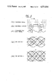
- an eye pattern is used. It is displayed by superposing equalized playback signals arrayed in a time sequence, at respective bit periods. It is exemplified in FIGS. 5(a)-5(e).
- FIGS. 5(a) to 5(e) show a recording information, a recording current, equalized playback signals and eye patterns by taking the NRZI recording system as an example.
- the reversals 17 and 18 of the recording current in FIG. 5(b) are the same reversals of from a lower level to a higher level. Since, however, the respective adjacent recording current components differ as being “0" and “1", and “1” and “0”, equalized playback signals come to have unequal amplitudes as respectively shown at numerals 19 and 20 in FIG. 5(c). Therefore, when the playback signals are displayed as the eye pattern, the eye portion of a hatched part 21 becomes small as shown by an eye pattern 1 in FIG. 5(d). In the amplitude detection, the level comparison is performed by setting the detection level VTH at the center of the eye. When this eye is small, a margin for the signal-to-noise ratio lessens, and symbol errors increase.
- An eye pattern 2 in FIG. 5(e) is an equalized eye pattern synthesized by superposing one playback waveform, and shows a state free from the nonlinear distortion.
- an eye is large as shown at numeral 22 in the figure, the signal-to-noise ratio has a wide margin, and there are few symbol errors in the amplitude detection.
- FIGS. 7(a) to 7(c) As a measure for removing the distortion of the playback signal in such magnetic recording and playback, there have heretofore been proposed methods in which additional current reversal points are provided as shown in FIGS. 6(a) and 6(b) and FIGS. 7(a) to 7(c) (Japanese Patent Application Publication No. 55-40921).
- playback waveforms which are obtained in correspondence with the reversals 23, 24 and 25 of a recording current in FIG. 7(b) are as shown at 23', 24' and 25' in FIG. 7(c), respectively, and a playback pulse signal is narrowed on the basis of a waveform (23'+24'+25') obtained as the sum of the aforementioned playback waveforms.
- these methods exhibit some effects for reducing the distortions of the playback waveforms attributed to the linear intersymbol interference shown at 4 and 5 in FIG. 1(c) and the nonlinear intersymbol interference shown at 16 in FIG. 4(e).
- These methods relieve the interaction between bits by taking note of only the reversal of one recording current and provide for the spreading of one bit thereof and do not take into account the differences of the nonlinear distortions dependent upon the recording patterns, and the differences being the peculiar property of the magnetic recording and playback.
- the present invention has for its object to make the eye of the eye pattern of equalized playback signals large by varying the reversal amplitude of a head driving current in accordance with recording patterns, thereby to make nonlinear distortions constant irrespective of recording patterns and to make the amplitudes of playback signal pulses constant.
- the present invention consists in that in a case where in a magnetic head driving current, its polarity continues for at least 1.5 times of a bit period, the current reversal amplitude of a current reversal point at which the polarity is started is made small relative to the other current reversal amplitude, thereby to make the amplitudes of playback signal pulses constant irrespective of recording patterns and to make the eye of an eye pattern large.
- the expression "at least 1.5 times of a bit period” signifies “at least 2 times of the bit period” in recording systems, such as NRZ and NRZI, wherein the time interval at which the current reversal occurs is an integral number of times of the bit period, and it signifies “at least 1.5 times of the bit period” in recording systems, such as MFM and M 2 , wherein the time interval at which the current reversal occurs becomes 1 time, 1.5 times, 2 times . . . of the bit period".
- FIG. 1(a) through FIG. 7(c) concern prior arts, in which
- FIGS. 1(a) to 1(c) are diagrams showing the correspondence of recording information, a recording current and a playback signal
- FIGS. 2(a) to 2(c) and FIGS. 3(a) and 3(b) are diagrams for explaining equalization
- FIGS. 4(a) to 4(e) are diagrams for explaining the nonlinear distortion of a playback waveform
- FIGS. 5(a) to 5(e) are diagrams for explaining an eye pattern
- FIGS. 6(a) and 6(b) and FIGS. 7(a) to 7(c) are diagrams showing prior-art methods of suppressing the distortions of playback waveforms.
- FIG. 8(a) through FIG. 18(q) concern the present invention, in which
- FIGS. 8(a) to 8(d) and FIG. 9 are diagrams for explaining a cause for the occurrence of a nonlinear distortion
- FIGS. 10(a) to 10(d) are diagrams for explaining the principle of the present invention.
- FIGS. 11(a) to 11(c) are diagrams showing a recording current waveform at the time when the present invention is applied to the NRZI recording system;
- FIGS. 12(a) to 12(e) are diagrams showing recording current waveforms at the time when the present invention is applied to prior-art methods of suppressing playback waveform distortions;
- FIGS. 13(a) to 13(g) are diagrams showing recording current waveforms at the time when the present invention is applied to the NRZ, MFM and M 2 recording system;
- FIGS. 16(A) and 16(B) are diagrams showing the effects of the present invention.
- FIG. 17 is a circuit diagram for realizing the present invention with the NRZ recording system.
- FIGS. 18(a) to 18(q) are time charts for explaining the operations of the circuit in FIG. 17.
- FIGS. 8(a), 8(b), 8(c) and 8(d) show recording information of "01110", a recording current waveform in a prior art, a magnetic pattern on a medium, and a playback signal by taking the recording system NRZI as an example, respectively.
- the combination of "0" and “1" in the recording information of FIG. 8(a) shall be called the recording pattern.
- Letter A, B or C in FIG. 8(b) indicates a change of the recording current from a low level to a high level or vice versa.
- the change shall be called the current reversal point, and the magnitude I o of the change shall be called the current reversal amplitude.
- the high level or low level of the recording current shall be called the polarity of the current.
- the magnetic pattern which corresponds to the recording current waveform in FIG. 8(b) is formed on the medium.
- the magnitudes of magnetization on the medium at 26', 27', 28' and 29' in FIG. 8(c) correspond to equal levels of the recording current, they become respectively different values on account of nonlinear interactions which occur in the writing operations of the respective bits.
- the interaction is considered to be caused by both a recording demagnetization action in the magnetizing process and a demagnetization action due to a demagnetizing field arising from the magnetization of the medium.
- the recording demagnetization will be first explained by considering the hysteresis of the formation of the magnetized part 26' in FIG. 8(c).
- a magnetic head lies at the point 26' of the medium
- the magnetization is written in a minus value by a minus intense head field.
- a plus field is applied to the point 30' of the medium so as to write plus magnetization. Since, however, the head field has a spacial spread, the plus field acts on the point 26' of the medium in the plus writing operation of the point 30' and functions to demagnetize the original minus magnetization of the point 26'. This is termed the recording demagnetization.
- the value of the magnetization of the part 30' changes in correspondence with the reversal 30 of the recording current, and a magnetic field arises from the magnetization change.
- This demagnetizing field acts in the direction of reducing the magnetization of the point 26'. Since the magnitude of the demagnetizing field is approximately in inverse proportion to the distance on the medium, the demagnetization of the point 26' attributed to such demagnetizing field is most affected by the magnetization change of the part 30' and is little affected by magnetization changes of parts 31' and 32'. Accordingly, the demagnetization action by the demagnetizing field is influenced most intensely by the adjacent recording pattern likewise to that by the recording demagnetization.
- FIG. 9 shows the so-called hysteresis loop illustrative of the relationship between the magnetic field and the magnetization of a medium.
- a larger loop ABCDA on the outer side is termed the major loop, and a loop on the inner side the minor loop.
- the hysteresis of the magnetization of the point 27' in FIG. 8(c) will be described with reference to the hysteresis loop.
- the medium is A.C.-demagnetized. Therefore, before the recording is performed, the magnetization of the point 27' in FIG. 8(c) is in the unmagnetized state and lies at a point 0 in FIG. 9. While the parts 26 and 30 in FIG. 8(b) are being recorded, a minus magnetic field is applied to the point 27' by both the demagnetization actions attributed to the recording demagnetization and the demagnetizing field. At this time, accordingly, the magnetization of the point 27' shifts from the point 0 to a point E in FIG. 9. Subsequently, a plus intense head field is applied during the writing of the point 27 in FIG. 8(b), and hence, the corresponding magnetization shifts from the point E to a point G on the hysteresis loop of FIG. 9.
- the magnetization of the point 27' is brought from the point G in FIG. 9 back to a point J of minus field by the writing of parts 31 and 28 in FIG. 8(b).
- the value of the magnetization of the point 27' is greatly affected by the magnitude of the aforementioned minus field, namely, a demagnetizing field attributed to the writing of the parts 31 and 28 in FIG. 8(b).
- the magnetization of the point 27' changes to finally become a value K in FIG. 9.
- the value of the magnetization of the medium is influenced most intensely by the recording pattern which is 1 bit later in time.
- the magnitudes of magnetization of the points 26', 27', 28' and 29' in FIG. 8(c) will be considered. Since the respectively succeeding bits of the points 26, 27 and 28 have the respectively opposite polarities of the recording current at the points 27, 28 and 29, the magnitudes of magnetization decrease due to the demagnetization of the recording demagnetization as well as the demagnetizing fields.
- the magnetization of the point 29' is little demagnetized because of the next bit being "0" and finally becomes greater than the values of magnetization of the points 26', 27' and 28' in FIG.
- the playback signal of the current reversal which precedes by 1 bit to the recording information having no current reversal becomes larger in amplitude than the other playback signal.
- the present invention consists in enlarging the recording current reversal amplitude of a bit subject to an intense demagnetizing action, thereby to make the magnitudes of magnetization on a medium constant irrespective of recording patterns and to make the amplitudes of playback signals constant.
- the bit subject to the intense demagnetizing action is a bit at which a recording current reverses and which precedes directly to a bit where the recording current reverses.
- the present invention is expressed in other words as follows.
- a playback signal pulse obtained when the current reversal at which the particular polarity begins is recorded and played back, becomes greater than the other playback pulses. Therefore, the amplitude of the particular current reversal is made small relative to those of the other current reversals, thereby to make the amplitudes of the playback signal pulses equal irrespective of the recording patterns.
- FIGS. 10(a)-10(d) show a recording information signal, a recording current, a magnetic pattern and a playback signal, respectively.
- symbols 33, 33' and 33" indicate the prior-art system corresponding to FIGS. 8(a)-8(d), and symbols 34, 34' and 34" indicate the system of the present invention by which a current reversal amplitude Iv preceding directly to a bit where the recording current does not reverse is made small relative to the other current reversal amplitude Io.
- the current reversal amplitude of the part 34 in FIG. 10(b) is smaller than that of the part 33, with the results that the magnetization 34' of a medium has a smaller value than the magnetization 33'. Therefore, the change of the magnetization 34' becomes smaller than that of the magnetization 33', and the playback signal 34" becomes smaller than the playback signal 33" in the prior art and has the same amplitude value as the amplitudes 30" and 31" of the other playback signals.
- FIG. 11(a)-11(c) compare and illustrate a recording current waveform in the prior-art system (FIG. 11(b)) and a recording current waveform according to the present invention (FIG. 11(c), by the use of a recording pattern having a large number of bits.
- the current amplitude of bit "1" preceding directly to bit "0" is made small relative to the other current amplitude.
- FIGS. 12(a)-12(e) illustrate an example in which the present invention is applied to recording current waveforms provided with additional current reversal points (refer to FIGS. 6(a) and 6(b) and FIGS. 7(a) to 7(c)).
- a recording current 1 in FIG. 12(b) corresponds to the prior-art system wherein one additional current reversal point is provided for one current reversal, while a recording current 2 in FIG. 12(c) is a current waveform at the time when the present invention is applied to the current waveform of the prior art.
- the amplitude of the additional current reversal point thereof is made small relative to the other additional current reversal point, or no additional current reversal point is provided. (Refer to parts 35, 36 and 37 and 35', 36' and 37' in the figures.)
- a recording current 3 in FIG. 12(d) is a current waveform of the prior-art system in which two additional current reversal points are provided for one current reversal. It is a recording current 4 in FIG. 12(e) that is obtained by applying the present invention to the current waveform of the prior art.
- additional current reversal points 38, 39 and 40 in FIG. 12(d) are made small as shown at 38', 39' and 40' in FIG. 12(e), or no additional current reversal point is provided.
- FIGS. 13(a)-13(g) show a recording current waveform in a prior art and recording current waveforms according to the present invention in the recording systems NRZ, MFM and M 2 , with respect to recording information in FIG. 13(a).
- the time intervals at which the recording current reverses become 1 times, 1.5 time, 2 times, . . . of the bit period.
- the amplitude of the leading current reversal is made smaller than the other current amplitude.
- FIGS. 14(A) and 14(B) compare and illustrate the eye patterns of the prior-art system and the system according to the present invention by taking the NRZI recording system as an example.
- the "eye opening" is defined in order to indicate the size of an eye quantitatively.
- the eye opening is defined as the value of E 2 /E 1 where E 1 denotes the amplitude of the eye of the eye pattern obtained by the superposition of the 1-bit playback pulse signals as shown by the eye pattern 2 in FIG. 5(e), and E 2 denotes the amplitude of an eye obtained by recording and playing back a random pattern.
- E 1 denotes the amplitude of the eye of the eye pattern obtained by the superposition of the 1-bit playback pulse signals as shown by the eye pattern 2 in FIG. 5(e)
- E 2 denotes the amplitude of an eye obtained by recording and playing back a random pattern.
- the eye opening in the prior-art system is 60%, whereas the eye opening becomes 85% in the system according to the present invention, so that
- FIGS. 15(A) and 15(B) illustrate the variation of the eye opening at the time when the ratio Io/Iv of the current reversal amplitude of the present invention is changed.
- Io/Iv 1 (one) corresponds to the recording current waveform of the prior art, and the eye opening in that case is assumed to be 50% by way of example.
- Numeral 61 in FIG. 15(B) illustrates the eye opening at the time when Io/Iv is gradually increased. From this figure, it is understood that the effect of the present invention appears when 1 ⁇ Io/Iv ⁇ 1.4.
- FIGS. 16(A) and 16(B) illustrate a recording current waveform (FIG. 16(A)) at the time when the part of the recording current where the amplitude is reduced is made equal to 1 bit period, and the effect (FIG. 16(B)) thereof. It is understood that, in this case, the effect of the present invention appears at 1 ⁇ Io/Iv' ⁇ 1.3 as indicated by a curve 62 in FIG. 16(B).
- FIG. 17 and FIGS. 18(a)-18(q) show an example in which the present invention is applied to the NRZ recording system, and are a circuit diagram and time charts respectively.
- FIG. 17 is the diagram of the circuit which realizes the present invention on the basis of the idea described above.
- FIGS. 18(a)-18(q) are the charts illustrative of current waveforms corresponding to various points in the circuit diagram of FIG. 17 when the recording information of FIG. 18(a) are taken as an example.
- Numeral 70 in FIG. 17 indicates a data input terminal, to which the recording current of the NRZ recording system is applied.
- Numeral 79 in the figure indicates an input terminal of a clock signal for operating flip-flops.
- Data is applied to a flip-flop 71 in the figure, to obtain outputs (b) and (i).
- the driving currents (b) and (i) correspond to FIGS. 18(b) and 18(i) respectively.
- the signal (b) enters a flip-flop 72 in FIG. 17, the output (c) of which is a signal in FIG. 18(c) and is a signal delayed by 1 bit and having the opposite polarity with respect to the signal (b).
- FIG. 18(d) A signal (d) obtained by passing the signals (c) and (b) through OR circuits is shown in FIG. 18(d), and is a code of x 2 +x 1 .
- FIG. 18(e) When the signal (d) is applied to a flip-flop 73 in FIG. 17, a signal in FIG. 18(e) is obtained. This code is a signal with x 2 +x 1 delayed, and becomes x 3 +x 2 .
- a signal in FIG. 18(f) By passing the signals (e) and (b) through OR circuits in FIG. 17, a signal in FIG. 18(f) is obtained.
- the code (f) is x 1 +x 2 +x 3 , which becomes the code x 4 .
- the code (f) becomes a signal which has the polarity of a low level in only the second "0" bit of the code "100" in FIG. 18(a).
- a signal (g) is obtained.
- the clock of the flip-flop is delayed by only half of the bit period by means of a switch 80 in the figure
- the signal (g) becomes such that the signal (f) is delayed by the half bit period and has its polarity reversed.
- a signal in FIG. 18(h) is obtained by passing the signals (g) and (f) through OR circuits.
- a signal (p) is obtained by passing the original signal (b) through a flip-flop 75 in FIG. 17.
- the signal (h) corresponds to the initial current amplitude reversal point in a case where the polarity of the low level continues for at least 2 times of the bit period.
- the signal (i) in FIG. 17 with the polarity of the recording current of the original NRZ system reversed is passed through a circuit 76 to 78 of the same arrangement as that 72 to 74, thereby to obtain a signal (o).
- the signal (h) and the signal (o) are attenuated a ⁇ times by an attenuator 81 and an attenuator 82, respectively.
- a differential amplifier indicated at numeral 83, along with the signal (p)
- a signal in FIG. 18(q) is obtained. This is the recording current waveform of the present invention, and is taken out from an output terminal 84.
- the part of the recording current in which the amplitude is reduced is the half bit period.
- the aforementioned part can be made another period, such as 1 bit period, by properly adjusting the delay time of the clock pulse to be impressed on the flip-flops 74 and 78.
- the present invention thus far described in detail can make the amplitudes of playback pulse signals constant irrespective of recording patterns, and in turn, can reduce symbol errors in the playback operation, so that it is very effective as a magnetic recording and playback method for digital information such as in high density video recording of video tape recorders, etc.
Landscapes
- Engineering & Computer Science (AREA)
- Signal Processing (AREA)
- Digital Magnetic Recording (AREA)
Applications Claiming Priority (2)
| Application Number | Priority Date | Filing Date | Title |
|---|---|---|---|
| JP56-127780 | 1981-08-17 | ||
| JP56127780A JPS5829110A (ja) | 1981-08-17 | 1981-08-17 | デイジタル信号の磁気記録方法 |
Publications (1)
| Publication Number | Publication Date |
|---|---|
| US4521816A true US4521816A (en) | 1985-06-04 |
Family
ID=14968495
Family Applications (1)
| Application Number | Title | Priority Date | Filing Date |
|---|---|---|---|
| US06/405,342 Expired - Fee Related US4521816A (en) | 1981-08-17 | 1982-08-05 | Magnetic recording method for digital signal |
Country Status (4)
| Country | Link |
|---|---|
| US (1) | US4521816A (ja) |
| JP (1) | JPS5829110A (ja) |
| DE (1) | DE3230551C2 (ja) |
| GB (1) | GB2104758B (ja) |
Cited By (4)
| Publication number | Priority date | Publication date | Assignee | Title |
|---|---|---|---|---|
| US4796109A (en) * | 1984-06-05 | 1989-01-03 | Unisys Corp. | Method for testing components of a magnetic storage system |
| US4809304A (en) * | 1985-03-18 | 1989-02-28 | Bull, S. A. | Method of extracting a synchronous clock signal from a single- or double-density coded signal, and apparatus for performing the method |
| US5206853A (en) * | 1990-02-28 | 1993-04-27 | Matsushita Electric Industrial Co., Ltd. | Apparatus and method for detecting intersymbol interference |
| US5418670A (en) * | 1991-07-29 | 1995-05-23 | Eastman Kodak Company | Magnetic recording medium having a servo pattern of the intermittent type with compensation for suppressing self-generated residual fields |
Citations (4)
| Publication number | Priority date | Publication date | Assignee | Title |
|---|---|---|---|---|
| US3503059A (en) * | 1967-03-22 | 1970-03-24 | Ibm | Pulse crowding compensation for magnetic recording |
| US3618119A (en) * | 1970-03-13 | 1971-11-02 | Storage Technology Corp | Compensation in a magentic write circuit |
| US3665485A (en) * | 1969-06-11 | 1972-05-23 | Petter Instr Co Inc | Method and system for high density recording of information on premagnetized magnetic tape |
| US4167761A (en) * | 1978-04-03 | 1979-09-11 | Sperry Rand Corporation | Precedent and subsequent minor transitions to alleviate pulse crowding |
-
1981
- 1981-08-17 JP JP56127780A patent/JPS5829110A/ja active Pending
-
1982
- 1982-08-05 US US06/405,342 patent/US4521816A/en not_active Expired - Fee Related
- 1982-08-16 GB GB08223499A patent/GB2104758B/en not_active Expired
- 1982-08-17 DE DE3230551A patent/DE3230551C2/de not_active Expired
Patent Citations (4)
| Publication number | Priority date | Publication date | Assignee | Title |
|---|---|---|---|---|
| US3503059A (en) * | 1967-03-22 | 1970-03-24 | Ibm | Pulse crowding compensation for magnetic recording |
| US3665485A (en) * | 1969-06-11 | 1972-05-23 | Petter Instr Co Inc | Method and system for high density recording of information on premagnetized magnetic tape |
| US3618119A (en) * | 1970-03-13 | 1971-11-02 | Storage Technology Corp | Compensation in a magentic write circuit |
| US4167761A (en) * | 1978-04-03 | 1979-09-11 | Sperry Rand Corporation | Precedent and subsequent minor transitions to alleviate pulse crowding |
Cited By (4)
| Publication number | Priority date | Publication date | Assignee | Title |
|---|---|---|---|---|
| US4796109A (en) * | 1984-06-05 | 1989-01-03 | Unisys Corp. | Method for testing components of a magnetic storage system |
| US4809304A (en) * | 1985-03-18 | 1989-02-28 | Bull, S. A. | Method of extracting a synchronous clock signal from a single- or double-density coded signal, and apparatus for performing the method |
| US5206853A (en) * | 1990-02-28 | 1993-04-27 | Matsushita Electric Industrial Co., Ltd. | Apparatus and method for detecting intersymbol interference |
| US5418670A (en) * | 1991-07-29 | 1995-05-23 | Eastman Kodak Company | Magnetic recording medium having a servo pattern of the intermittent type with compensation for suppressing self-generated residual fields |
Also Published As
| Publication number | Publication date |
|---|---|
| DE3230551A1 (de) | 1983-03-03 |
| DE3230551C2 (de) | 1985-02-14 |
| JPS5829110A (ja) | 1983-02-21 |
| GB2104758B (en) | 1985-07-24 |
| GB2104758A (en) | 1983-03-09 |
Similar Documents
| Publication | Publication Date | Title |
|---|---|---|
| JPH0132591B2 (ja) | ||
| US5166955A (en) | Signal detection apparatus for detecting digital information from a PCM signal | |
| JPS5834002B2 (ja) | デイジタル信号の磁気記録再生方式 | |
| US6335949B1 (en) | Non-linear signal receiver | |
| EP0385867A2 (en) | Digital signal reproducing apparatus | |
| US5561647A (en) | System for detection of readout signals from optical disc | |
| JP2540805B2 (ja) | ディジタル信号の伝送装置 | |
| GB2104758A (en) | A method of magnetically recording digital signals | |
| US20040037372A1 (en) | Media noise post-processor with varying threshold | |
| JP4011860B2 (ja) | 垂直磁気記録方式の磁気ディスク装置及び書き込み補償方法 | |
| US6288859B1 (en) | Device for write compensation in magnetic-media recording | |
| KR940003663B1 (ko) | 디지탈 신호 재생회로 | |
| JP2787895B2 (ja) | 情報記録再生装置 | |
| JP2551235B2 (ja) | 適応型フィルタ制御方法 | |
| JP2845878B2 (ja) | デジタル同期信号の記録再生方法 | |
| JPH01199306A (ja) | 再生歪補償装置 | |
| JP2834182B2 (ja) | デイジタル信号の変調および復調方式 | |
| JP2697647B2 (ja) | 記録信号補償回路 | |
| JP2917191B2 (ja) | ディジタル信号再生装置 | |
| EP0992036B1 (en) | Device for write compensation in magnetic-media recording | |
| KR0151030B1 (ko) | 통합등화기를 갖는 디지탈 기록재생장치 | |
| KR0129966B1 (ko) | 데이타 재생회로 | |
| JPH04232668A (ja) | ディジタル情報検出装置 | |
| JPH037176B2 (ja) | ||
| Lin et al. | Post compensation for nonlinear distortions in PRML recording channel |
Legal Events
| Date | Code | Title | Description |
|---|---|---|---|
| AS | Assignment |
Owner name: HITACHI DENSHI KABUSHIKI KAISHA 23-2, KANDASUDACHO Free format text: ASSIGNMENT OF ASSIGNORS INTEREST.;ASSIGNORS:KOUGAMI, AKIHIKO;MITA, SEIICHI;KIRINO, TORU;AND OTHERS;REEL/FRAME:004352/0147 Effective date: 19820721 |
|
| FPAY | Fee payment |
Year of fee payment: 4 |
|
| FEPP | Fee payment procedure |
Free format text: PAYOR NUMBER ASSIGNED (ORIGINAL EVENT CODE: ASPN); ENTITY STATUS OF PATENT OWNER: LARGE ENTITY |
|
| FEPP | Fee payment procedure |
Free format text: PAYER NUMBER DE-ASSIGNED (ORIGINAL EVENT CODE: RMPN); ENTITY STATUS OF PATENT OWNER: LARGE ENTITY |
|
| FPAY | Fee payment |
Year of fee payment: 8 |
|
| REMI | Maintenance fee reminder mailed | ||
| LAPS | Lapse for failure to pay maintenance fees | ||
| FP | Lapsed due to failure to pay maintenance fee |
Effective date: 19970604 |
|
| STCH | Information on status: patent discontinuation |
Free format text: PATENT EXPIRED DUE TO NONPAYMENT OF MAINTENANCE FEES UNDER 37 CFR 1.362 |