US4548656A - Method and apparatus for reducing the watt loss of a grain-oriented electromagnetic steel sheet and a grain-oriented electromagnetic steel sheet having a low watt loss - Google Patents
Method and apparatus for reducing the watt loss of a grain-oriented electromagnetic steel sheet and a grain-oriented electromagnetic steel sheet having a low watt loss Download PDFInfo
- Publication number
- US4548656A US4548656A US06/398,334 US39833482A US4548656A US 4548656 A US4548656 A US 4548656A US 39833482 A US39833482 A US 39833482A US 4548656 A US4548656 A US 4548656A
- Authority
- US
- United States
- Prior art keywords
- steel sheet
- grain
- oriented electromagnetic
- electromagnetic steel
- watt loss
- Prior art date
- Legal status (The legal status is an assumption and is not a legal conclusion. Google has not performed a legal analysis and makes no representation as to the accuracy of the status listed.)
- Expired - Fee Related
Links
Images



Classifications
-
- C—CHEMISTRY; METALLURGY
- C21—METALLURGY OF IRON
- C21D—MODIFYING THE PHYSICAL STRUCTURE OF FERROUS METALS; GENERAL DEVICES FOR HEAT TREATMENT OF FERROUS OR NON-FERROUS METALS OR ALLOYS; MAKING METAL MALLEABLE, e.g. BY DECARBURISATION OR TEMPERING
- C21D7/00—Modifying the physical properties of iron or steel by deformation
- C21D7/02—Modifying the physical properties of iron or steel by deformation by cold working
- C21D7/04—Modifying the physical properties of iron or steel by deformation by cold working of the surface
- C21D7/06—Modifying the physical properties of iron or steel by deformation by cold working of the surface by shot-peening or the like
-
- C—CHEMISTRY; METALLURGY
- C21—METALLURGY OF IRON
- C21D—MODIFYING THE PHYSICAL STRUCTURE OF FERROUS METALS; GENERAL DEVICES FOR HEAT TREATMENT OF FERROUS OR NON-FERROUS METALS OR ALLOYS; MAKING METAL MALLEABLE, e.g. BY DECARBURISATION OR TEMPERING
- C21D8/00—Modifying the physical properties of ferrous metals or ferrous alloys by deformation combined with, or followed by, heat treatment
- C21D8/12—Modifying the physical properties of ferrous metals or ferrous alloys by deformation combined with, or followed by, heat treatment during manufacturing of articles with special electromagnetic properties
- C21D8/1294—Modifying the physical properties of ferrous metals or ferrous alloys by deformation combined with, or followed by, heat treatment during manufacturing of articles with special electromagnetic properties involving a localised treatment
-
- H—ELECTRICITY
- H01—ELECTRIC ELEMENTS
- H01F—MAGNETS; INDUCTANCES; TRANSFORMERS; SELECTION OF MATERIALS FOR THEIR MAGNETIC PROPERTIES
- H01F1/00—Magnets or magnetic bodies characterised by the magnetic materials therefor; Selection of materials for their magnetic properties
- H01F1/01—Magnets or magnetic bodies characterised by the magnetic materials therefor; Selection of materials for their magnetic properties of inorganic materials
- H01F1/03—Magnets or magnetic bodies characterised by the magnetic materials therefor; Selection of materials for their magnetic properties of inorganic materials characterised by their coercivity
- H01F1/12—Magnets or magnetic bodies characterised by the magnetic materials therefor; Selection of materials for their magnetic properties of inorganic materials characterised by their coercivity of soft-magnetic materials
- H01F1/14—Magnets or magnetic bodies characterised by the magnetic materials therefor; Selection of materials for their magnetic properties of inorganic materials characterised by their coercivity of soft-magnetic materials metals or alloys
- H01F1/16—Magnets or magnetic bodies characterised by the magnetic materials therefor; Selection of materials for their magnetic properties of inorganic materials characterised by their coercivity of soft-magnetic materials metals or alloys in the form of sheets
Definitions
- the present invention relates to a method and apparatus for reducing the watt loss of a grain-oriented electromagnetic steel sheet and a grain-oriented electromagnetic steel sheet having a low watt loss.
- a grain-oriented electromagnetic steel sheet consists of crystal grains, the direction of easy magnetization, i.e. the [100] axis, of which is parallel to the rolling direction, and grain-orientation of a grain-oriented electromagnetic steel sheet occurs during final annealing, in which secondary recrystallization takes place.
- Grain-oriented electromagnetic steel sheets which are conventionally produced have either a single orientation, in which the (110) plane and [100] axis of the crystal grains are parallel to the sheet surface and the rolling direction, respectively, or a double orientation, in which the (100) plane and [001] axis of the crystal grains are parallel to the sheet surface and the rolling direction, respectively.
- the watt loss of a grain-oriented electromagnetic steel sheet is dependent on the exciting characteristic and the grain size. More specifically, the watt loss of a grain-oriented electromagnetic steel sheet can be reduced by enhancing the exciting characteristic and by decreasing the grain size.
- the exciting characteristic of a grain-oriented electromagnetic steel sheet is usually enhanced by increasing the grain size.
- the grain size of a grain-oriented electromagnetic steel sheet is conventionally increased by increasing the degree of orientation, but this increase simultaneously involves a factor which disadvantageously increases watt loss and a factor which advantageously decreases watt loss by increasing the exciting characteristic.
- burrs which are formed at both ends of the scratches during scratching, protrude from the sheet surface, and when sections of a grain-oriented electromagnetic steel sheet are laminated, the burrs on said sections protrude through the insulating film applied to the adjacent section. Proposals have been made for eliminating the disadvantages due to serration or scratching and for reducing watt loss to below that attained by enhancing the degree of orientation.
- a method for reducing the watt loss of a grain-oriented electromagnetic steel sheet according to the present invention is characterized in that after final annealing of a steel sheet during which grain-orientation occurs, particles are projected onto substantially linear selected portions of the grain-oriented electromagnetic steel sheet, thereby producing a strain in the spot-formed regions of said selected portions of the grain-oriented electromagnetic steel sheet.
- An apparatus for reducing the watt loss of a grain-oriented electromagnetic steel sheet according to the present invention comprises:
- a stationary plate including at least one slit
- a slidable plate capable of reciprocating which is in contact with said stationary plate and includes a slit capable of registering with said at least one slit of said stationary plate;
- At least one means for projecting particles oriented toward said stationary plate.
- Another apparatus for reducing the watt loss of a grain-oriented electromagnetic steel sheet according to the present invention comprises:
- a rotatable drum having at least one slit on the cylindrical wall thereof;
- At least one means for projecting particles said means being located inside or outside said rotatable drum.
- a grain-oriented electromagnetic steel sheet having a low watt loss according to the present invention is characterized in that substantially linear selected portions of said grain-oriented electromagnetic steel sheet have spotlike indentations, which are formed due to the projection of particles, and in that strain is produced due to said spotlike indentations.
- a grain-oriented electromagnetic steel sheet having a low watt loss according to the present invention is also characterized in that substantially linear selected portions of an insulating film, which is applied to said grain-oriented electromagnetic steel sheet, have spotlike identations which are formed due to the projection of particles and in that strain is produced in said grain-oriented electromagnetic steel sheet due to said spotlike indentations.
- the word "grain-oriented electromagnetic steel sheet” herein includes a grain-oriented electromagnetic steel strip.
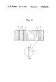
- FIG. 1 is a plan view of an embodiment of an apparatus according to the present invention.
- FIG. 2 illustrates how steel shots are projected onto one substantially linear selected portion of a grain-oriented electromagnetic steel sheet in accordance with the method of the present invention
- FIG. 3 which is similar to FIG. 2, illustrates how projection of the steel shots is interrupted
- FIG. 4 shows embodiments of the substantially linear selected portions of a grain-oriented electromagnetic steel sheet in which strain is produced due to the projection of particles
- FIG. 5 is a view of an embodiment of an apparatus according to the present invention.
- FIG. 6 is a cross-sectional view of the apparatus shown in FIG. 5;
- FIG. 7 is a view of another embodiment of an apparatus according to the present invention.
- FIG. 8 is a graph showing the magnetic flux densit (B 8 ) and the watt loss (W 17/50 ) obtained as a result of the projection of particles.
- steel sheet 1 contains 4.0% or less of silicon and, as stated hereinabove, has been subjected to final annealing, during which grain orientation occurs.
- steel sheet 1 when steel sheet 1 is subjected to the projection of particles, steel sheet 1 may or may not be provided with an insulating film (not shown) thereon.
- the insulating film (not shown) may be a secondary insulating film composed of a phosphate or an organic compound and may have a thickness of from 1 to 5 microns.
- the projection of particles may be carried out after a heat-flattening step.
- Steel sheet 1 is transferred in the direction indicated by the arrow (FIG. 1) and along a pass line.
- Stationary plate 3 is disposed above steel sheet 1 so as to maintain a predetermined distance between stationary plate 3 and steel sheet 1.
- Slidable plate 4 is located on stationary plate 3 and is connected to drive means 5, e.g., a hydraulic or pneumatic cylinder, via piston rod 6. Slidable plate 4 is therefore caused to reciprocate by drive means 5 when slidable plate 4 is in contact with stationary plate 3.
- Stationary plate 3 and slidable plate 4 are each provided with slit 2, the length of slit 2 being slightly greater than the width of steel sheet 1. Only when both slits 2 register due to the reciprocation of slidable plate 4 is particle-projecting means 10 (FIG.
- the projected particles not only steel shots but also other metal shots, organic resin particles, ceramic particles, and plant material particles can be used.
- the particles should have an essentially spherical shape. Projection of the particles can be carried out together with the injection of a fluid, such as a gas, e.g. air, or a gas-liquid mixture by means of at least one nozzle.
- a fluid such as a gas, e.g. air, or a gas-liquid mixture by means of at least one nozzle.
- Steel shots are conventionally used to descale rolled steel products.
- the impinging force of the steel shots according to the method of the present invention may not be as great as in the case of descaling, but an impinging force great enough to lightly strike the surface of steel sheet 1 is sufficient to reduce watt loss.
- the impinging force can be optionally adjusted depending upon the projection rate, the size, the material, and the hardness of the particles and upon the width of slits 2, as well as upon the tension which may be applied to steel sheet 1 being transferred. As in every method for producing strain in a grain-oriented electromagnetic steel sheet, a very large strain does not reduce watt loss but instead increases watt loss.
- a number of selected portions 8 of steel sheet 1 are linear, are substantially perpendicular to the rolling direction of steel sheet 1, and are parallel to one another.
- Each of selected portions 8 is a continuous line or curve.
- each of selected portions 8 may be a discontinuous line 8a or curve 8b.
- the width (S) of selected portions 8 is preferably from 0.1 to 0.3 mm.
- the spotlike indentations are indicated in FIG. 4 by reference numeral 11.
- the surface area of spotlike indentations 11 is considerably smaller than that of selected portions 8. Spotlike indentations 11 have a diameter of from approximately 60 to 80 microns and a depth of from approximately 3 to 5 microns.
- steel sheet 1 has no burrs around spotlike indentations 11 because indentations 11 are formed by the projection of steel shots (FIGS. 2 and 3).
- the regions of steel sheet 1 where strain is produced are substantially linear. Strictly speaking, such regions are defined by a number of small spot-formed regions which are substantially linearly arranged.
- selected portions 8 are linear and are substantially perpendicular to the rolling direction, the selected portions of a grain-oriented electromagnetic steel sheet having any other pattern may be subjected to the projection of particles. For example, discontinuous or continuous portions, which extend linearly or non-linearly in the rolling direction, may be subjected to the projection of particles.
- the distance between selected portions 8, hereinafter referred to as the linear-strain pitch (p), is optionally selected in the range of from 3 to 10 mm.
- the linear-strain pitch (p) can be adjusted by adjusting the reciprocating speed of slidable plate 4.
- a plurality of slits may be provided for stationary plate 3 and slidable plate 4.
- the transferring speed of steel sheet 1 must be increased, the reciprocating speed of slidable plate 4 must be increased, or the number of slits 2 must be increased.
- Increasing the number of slits 2 is more advantageous for decreasing the linear-strain pitch (p) than is increasing the reciprocating speed since the reciprocating speed is limited due to the construction of slidable plate 4 and drive means 5.
- an apparatus comprises rotatable drum 9, which can be rotated at a circumferential speed which is synchronous with the transferring speed of steel sheet 1.
- Slits 2 are formed on cylindrical wall 9a of rotatable drum 9, and the distance between slits 2 corresponds to the linear-strain pitch (p).
- Two impellers 10 project steel shots 7 through apertures 9b of the two side ends of rotatable drum 9 and slits 2 of rotatable drum 9 onto selected portions (not shown in FIG. 6).
- the device shown in FIGS. 5 and 6 can be used for treating a steel sheet which is transferred at a high line speed, for example, 100 meters/min or from 200 to less than 1,000 meters/min.
- impellers 10 are located within rotatable drum 9. Although two impellers 10 are shown, there may be only one or more than two provided that the particle projecting means is oriented toward the slits of the rotatable drum.
- the apparatuses according to the present invention are practical, simple, and inexpensive from the point of view of installation costs. Since steel shots 7 are recovered by a recovering device (not shown), the operation costs of the method according to the present invention are very low.
- Steel sheet 1 was a commercially available conventional grain-oriented steel sheet and had a thickness of 0.30 mm.
- Steel sheet 1 had the following magnetic properties before the projection of particles:
- W 17/50 is the watt loss at a magnetic flux density of 1.7 Tesla and at a frequency of 50 Hz.
- Nominal diameter of steel shots 7 0.3 mm.
- Projection rate from 3 to 30 kg/min/m 2 .
- Projection speed (speed of steel shots 7): from 12 to 52 meters/sec.
- Diameter of impellers 10 250 mm.
- Width of slits 2 approximately 0.7 mm.
- Transferring speed of steel sheet 1 (circumferential speed of rotatable drum 9): from 0.3 to 3.0 meters/min.
- W 17/50 which was measured by SST (measurement of a single sheet), and B 8 are given in FIG. 8.
- SST measurement of a single sheet
- B 8 was slightly reduced at a projection speed at which a reduction in W 17/50 was achieved. Such a slight reduction in B 8 practically involves no problem.
Landscapes
- Chemical & Material Sciences (AREA)
- Engineering & Computer Science (AREA)
- Physics & Mathematics (AREA)
- Crystallography & Structural Chemistry (AREA)
- Mechanical Engineering (AREA)
- Materials Engineering (AREA)
- Metallurgy (AREA)
- Organic Chemistry (AREA)
- Power Engineering (AREA)
- Dispersion Chemistry (AREA)
- Electromagnetism (AREA)
- Manufacturing & Machinery (AREA)
- Thermal Sciences (AREA)
- Manufacturing Of Steel Electrode Plates (AREA)
- Soft Magnetic Materials (AREA)
Applications Claiming Priority (2)
| Application Number | Priority Date | Filing Date | Title |
|---|---|---|---|
| JP56110858A JPS6056404B2 (ja) | 1981-07-17 | 1981-07-17 | 方向性電磁鋼板の鉄損低減方法およびその装置 |
| JP56-110858 | 1981-07-17 |
Publications (1)
| Publication Number | Publication Date |
|---|---|
| US4548656A true US4548656A (en) | 1985-10-22 |
Family
ID=14546450
Family Applications (1)
| Application Number | Title | Priority Date | Filing Date |
|---|---|---|---|
| US06/398,334 Expired - Fee Related US4548656A (en) | 1981-07-17 | 1982-07-15 | Method and apparatus for reducing the watt loss of a grain-oriented electromagnetic steel sheet and a grain-oriented electromagnetic steel sheet having a low watt loss |
Country Status (2)
| Country | Link |
|---|---|
| US (1) | US4548656A (ja) |
| JP (1) | JPS6056404B2 (ja) |
Cited By (10)
| Publication number | Priority date | Publication date | Assignee | Title |
|---|---|---|---|---|
| US4645547A (en) * | 1982-10-20 | 1987-02-24 | Westinghouse Electric Corp. | Loss ferromagnetic materials and methods of improvement |
| US4680062A (en) * | 1985-12-02 | 1987-07-14 | Allegheny Ludlum Corporation | Method for reducing core losses of grain-oriented silicon steel using liquid jet scribing |
| US4711113A (en) * | 1984-12-19 | 1987-12-08 | Allegheny Ludlum Corporation | Apparatus for reducing core losses of grain-oriented silicon steel |
| US4737203A (en) * | 1985-12-02 | 1988-04-12 | Allegheny Ludlum Corporation | Method for reducing core losses of grain-oriented silicon steel using liquid jet scribing |
| US4770720A (en) * | 1984-11-10 | 1988-09-13 | Nippon Steel Corporation | Method for producing a grain-oriented electrical steel sheet having a low watt-loss |
| US4846939A (en) * | 1986-01-11 | 1989-07-11 | Nippon Steel Corporation | Method for producing a grain-oriented electrical steel sheet having an ultra low watt loss |
| US4863531A (en) * | 1984-10-15 | 1989-09-05 | Nippon Steel Corporation | Method for producing a grain-oriented electrical steel sheet having a low watt loss |
| US4964922A (en) * | 1989-07-19 | 1990-10-23 | Allegheny Ludlum Corporation | Method for domain refinement of oriented silicon steel by low pressure abrasion scribing |
| US5123977A (en) * | 1989-07-19 | 1992-06-23 | Allegheny Ludlum Corporation | Method and apparatus for refining the domain structure of electrical steels by local hot deformation and product thereof |
| US5223048A (en) * | 1988-10-26 | 1993-06-29 | Kawasaki Steel Corporation | Low iron loss grain oriented silicon steel sheets and method of producing the same |
Families Citing this family (3)
| Publication number | Priority date | Publication date | Assignee | Title |
|---|---|---|---|---|
| JP2540780B2 (ja) * | 1994-05-19 | 1996-10-09 | 井関農機株式会社 | 施肥装置付き苗植機 |
| JP4569335B2 (ja) * | 2005-03-18 | 2010-10-27 | Jfeスチール株式会社 | 方向性電磁鋼板の製造方法および方向性電磁鋼板の鉄損低減装置 |
| JP5023552B2 (ja) * | 2006-05-19 | 2012-09-12 | Jfeスチール株式会社 | 低鉄損方向性電磁鋼板およびその製造方法 |
Citations (5)
| Publication number | Priority date | Publication date | Assignee | Title |
|---|---|---|---|---|
| US3647575A (en) * | 1968-10-17 | 1972-03-07 | Mannesmann Ag | Method for reducing lossiness of sheet metal |
| US3947296A (en) * | 1972-12-19 | 1976-03-30 | Nippon Steel Corporation | Process for producing steel sheet of cube-on-face texture having improved magnetic characteristics |
| US3990923A (en) * | 1974-04-25 | 1976-11-09 | Nippon Steel Corporation | Method of producing grain oriented electromagnetic steel sheet |
| US4293350A (en) * | 1978-07-26 | 1981-10-06 | Nippon Steel Corporation | Grain-oriented electromagnetic steel sheet with improved watt loss |
| US4363677A (en) * | 1980-01-25 | 1982-12-14 | Nippon Steel Corporation | Method for treating an electromagnetic steel sheet and an electromagnetic steel sheet having marks of laser-beam irradiation on its surface |
-
1981
- 1981-07-17 JP JP56110858A patent/JPS6056404B2/ja not_active Expired
-
1982
- 1982-07-15 US US06/398,334 patent/US4548656A/en not_active Expired - Fee Related
Patent Citations (5)
| Publication number | Priority date | Publication date | Assignee | Title |
|---|---|---|---|---|
| US3647575A (en) * | 1968-10-17 | 1972-03-07 | Mannesmann Ag | Method for reducing lossiness of sheet metal |
| US3947296A (en) * | 1972-12-19 | 1976-03-30 | Nippon Steel Corporation | Process for producing steel sheet of cube-on-face texture having improved magnetic characteristics |
| US3990923A (en) * | 1974-04-25 | 1976-11-09 | Nippon Steel Corporation | Method of producing grain oriented electromagnetic steel sheet |
| US4293350A (en) * | 1978-07-26 | 1981-10-06 | Nippon Steel Corporation | Grain-oriented electromagnetic steel sheet with improved watt loss |
| US4363677A (en) * | 1980-01-25 | 1982-12-14 | Nippon Steel Corporation | Method for treating an electromagnetic steel sheet and an electromagnetic steel sheet having marks of laser-beam irradiation on its surface |
Cited By (11)
| Publication number | Priority date | Publication date | Assignee | Title |
|---|---|---|---|---|
| US4645547A (en) * | 1982-10-20 | 1987-02-24 | Westinghouse Electric Corp. | Loss ferromagnetic materials and methods of improvement |
| US4863531A (en) * | 1984-10-15 | 1989-09-05 | Nippon Steel Corporation | Method for producing a grain-oriented electrical steel sheet having a low watt loss |
| US4960652A (en) * | 1984-10-15 | 1990-10-02 | Nippon Steel Corporation | Grain-oriented electrical steel sheet having a low watt loss |
| US4770720A (en) * | 1984-11-10 | 1988-09-13 | Nippon Steel Corporation | Method for producing a grain-oriented electrical steel sheet having a low watt-loss |
| US4711113A (en) * | 1984-12-19 | 1987-12-08 | Allegheny Ludlum Corporation | Apparatus for reducing core losses of grain-oriented silicon steel |
| US4680062A (en) * | 1985-12-02 | 1987-07-14 | Allegheny Ludlum Corporation | Method for reducing core losses of grain-oriented silicon steel using liquid jet scribing |
| US4737203A (en) * | 1985-12-02 | 1988-04-12 | Allegheny Ludlum Corporation | Method for reducing core losses of grain-oriented silicon steel using liquid jet scribing |
| US4846939A (en) * | 1986-01-11 | 1989-07-11 | Nippon Steel Corporation | Method for producing a grain-oriented electrical steel sheet having an ultra low watt loss |
| US5223048A (en) * | 1988-10-26 | 1993-06-29 | Kawasaki Steel Corporation | Low iron loss grain oriented silicon steel sheets and method of producing the same |
| US4964922A (en) * | 1989-07-19 | 1990-10-23 | Allegheny Ludlum Corporation | Method for domain refinement of oriented silicon steel by low pressure abrasion scribing |
| US5123977A (en) * | 1989-07-19 | 1992-06-23 | Allegheny Ludlum Corporation | Method and apparatus for refining the domain structure of electrical steels by local hot deformation and product thereof |
Also Published As
| Publication number | Publication date |
|---|---|
| JPS5816027A (ja) | 1983-01-29 |
| JPS6056404B2 (ja) | 1985-12-10 |
Similar Documents
| Publication | Publication Date | Title |
|---|---|---|
| US4548656A (en) | Method and apparatus for reducing the watt loss of a grain-oriented electromagnetic steel sheet and a grain-oriented electromagnetic steel sheet having a low watt loss | |
| US4203784A (en) | Grain oriented electromagnetic steel sheet | |
| EP3287533A1 (en) | Oriented magnetic steel plate | |
| CZ20014215A3 (cs) | Způsob zlepąení magnetických charakteristik křemíkových ocelových plechů s orientovanými zrny pro elektrotechnické účely působením laseru | |
| ES2153213T3 (es) | Proceso de fabricacion de bandas de acero de grano orientado para aplicaciones electricas, empezando con chapas finas. | |
| US4513597A (en) | Apparatus for reducing the watt loss of a grain-oriented electromagnetic steel sheet | |
| US5192585A (en) | Differential pressure sealing apparatus and method | |
| EP3760746B1 (en) | Grain-oriented electrical steel sheet | |
| EP1114871B1 (en) | Process for the production of material of metals and alloys having fine microstructure or fine nonmetallic inclusions and having less segregation of alloying elements. | |
| GB2104432A (en) | Method and apparatus for reducing the watt loss of a grain-oriented electromagnetic steel sheet and a grain-oriented electromagnetic steel sheet having a low watt loss | |
| US4711113A (en) | Apparatus for reducing core losses of grain-oriented silicon steel | |
| JP3882103B2 (ja) | 張力付与異方性被膜を有する低鉄損一方向性電磁鋼板 | |
| JP3651665B2 (ja) | プレス成形性および塗装後鮮映性に優れた冷延鋼板 | |
| EP0291952B1 (en) | Differential pressure sealing apparatus and method | |
| US4680062A (en) | Method for reducing core losses of grain-oriented silicon steel using liquid jet scribing | |
| EP0323155B1 (en) | Method for producing low iron loss grain oriented silicon steel sheets | |
| US5185043A (en) | Method for producing low iron loss grain oriented silicon steel sheets | |
| JPH05220503A (ja) | Fe−Ni系シャドウマスク用薄板およびその製造方法 | |
| JPH0739918A (ja) | 定摩擦、難異物付着性プロセスロール | |
| JP2672614B2 (ja) | 冷間圧延方法 | |
| JPS6096719A (ja) | 方向性けい素鋼板の鉄損軽減処理装置 | |
| US4737203A (en) | Method for reducing core losses of grain-oriented silicon steel using liquid jet scribing | |
| EP0302639A3 (en) | Grain oriented electromagnetic steel sheets having a very low iron loss and method of producing the same | |
| JP2853070B2 (ja) | シャドウマスク用薄板の製造方法 | |
| JPH03257121A (ja) | 歪取り焼鈍によって特性が劣化しない低鉄損方向性けい素鋼板の製造方法 |
Legal Events
| Date | Code | Title | Description |
|---|---|---|---|
| AS | Assignment |
Owner name: NIPPON STEEL CORPORATION 6-3 OTEMACHI 2-CHOME CHIY Free format text: ASSIGNMENT OF ASSIGNORS INTEREST.;ASSIGNORS:KIMOTO, TETSUO;ORITA, KIYOSHI;KUROKI, KATSURO;REEL/FRAME:004027/0425 Effective date: 19820709 |
|
| FEPP | Fee payment procedure |
Free format text: PAYOR NUMBER ASSIGNED (ORIGINAL EVENT CODE: ASPN); ENTITY STATUS OF PATENT OWNER: LARGE ENTITY |
|
| FPAY | Fee payment |
Year of fee payment: 4 |
|
| REMI | Maintenance fee reminder mailed | ||
| LAPS | Lapse for failure to pay maintenance fees | ||
| FP | Lapsed due to failure to pay maintenance fee |
Effective date: 19931024 |
|
| STCH | Information on status: patent discontinuation |
Free format text: PATENT EXPIRED DUE TO NONPAYMENT OF MAINTENANCE FEES UNDER 37 CFR 1.362 |