US4621833A - Control system for multistable suspension unit - Google Patents
Control system for multistable suspension unit Download PDFInfo
- Publication number
- US4621833A US4621833A US06/809,672 US80967285A US4621833A US 4621833 A US4621833 A US 4621833A US 80967285 A US80967285 A US 80967285A US 4621833 A US4621833 A US 4621833A
- Authority
- US
- United States
- Prior art keywords
- steering system
- vehicle
- suspension unit
- center position
- measuring
- Prior art date
- Legal status (The legal status is an assumption and is not a legal conclusion. Google has not performed a legal analysis and makes no representation as to the accuracy of the status listed.)
- Expired - Lifetime
Links
- 239000000725 suspension Substances 0.000 title claims abstract description 77
- 230000001133 acceleration Effects 0.000 claims abstract description 68
- 238000000034 method Methods 0.000 claims description 13
- 238000004364 calculation method Methods 0.000 claims description 9
- 230000014509 gene expression Effects 0.000 claims description 7
- 230000000284 resting effect Effects 0.000 claims description 7
- 230000008859 change Effects 0.000 claims description 3
- 238000006073 displacement reaction Methods 0.000 claims description 2
- 230000035939 shock Effects 0.000 description 21
- 239000006096 absorbing agent Substances 0.000 description 20
- 238000005070 sampling Methods 0.000 description 12
- 238000013016 damping Methods 0.000 description 6
- 230000007704 transition Effects 0.000 description 4
- 239000004020 conductor Substances 0.000 description 3
- 238000010586 diagram Methods 0.000 description 3
- 230000000694 effects Effects 0.000 description 3
- 238000005259 measurement Methods 0.000 description 3
- 230000007246 mechanism Effects 0.000 description 3
- 230000003044 adaptive effect Effects 0.000 description 2
- 230000005540 biological transmission Effects 0.000 description 2
- 238000010276 construction Methods 0.000 description 2
- 238000009434 installation Methods 0.000 description 2
- 238000004804 winding Methods 0.000 description 2
- 230000000712 assembly Effects 0.000 description 1
- 238000000429 assembly Methods 0.000 description 1
- 230000008901 benefit Effects 0.000 description 1
- 230000007812 deficiency Effects 0.000 description 1
- 239000012530 fluid Substances 0.000 description 1
- 239000000446 fuel Substances 0.000 description 1
- 238000002347 injection Methods 0.000 description 1
- 239000007924 injection Substances 0.000 description 1
- 238000004519 manufacturing process Methods 0.000 description 1
- 238000012986 modification Methods 0.000 description 1
- 230000004048 modification Effects 0.000 description 1
- 230000003287 optical effect Effects 0.000 description 1
- 230000008569 process Effects 0.000 description 1
- 230000004044 response Effects 0.000 description 1
- 239000003381 stabilizer Substances 0.000 description 1
- 230000001960 triggered effect Effects 0.000 description 1
Images


Classifications
-
- B—PERFORMING OPERATIONS; TRANSPORTING
- B60—VEHICLES IN GENERAL
- B60G—VEHICLE SUSPENSION ARRANGEMENTS
- B60G17/00—Resilient suspensions having means for adjusting the spring or vibration-damper characteristics, for regulating the distance between a supporting surface and a sprung part of vehicle or for locking suspension during use to meet varying vehicular or surface conditions, e.g. due to speed or load
- B60G17/015—Resilient suspensions having means for adjusting the spring or vibration-damper characteristics, for regulating the distance between a supporting surface and a sprung part of vehicle or for locking suspension during use to meet varying vehicular or surface conditions, e.g. due to speed or load the regulating means comprising electric or electronic elements
- B60G17/016—Resilient suspensions having means for adjusting the spring or vibration-damper characteristics, for regulating the distance between a supporting surface and a sprung part of vehicle or for locking suspension during use to meet varying vehicular or surface conditions, e.g. due to speed or load the regulating means comprising electric or electronic elements characterised by their responsiveness, when the vehicle is travelling, to specific motion, a specific condition, or driver input
- B60G17/0162—Resilient suspensions having means for adjusting the spring or vibration-damper characteristics, for regulating the distance between a supporting surface and a sprung part of vehicle or for locking suspension during use to meet varying vehicular or surface conditions, e.g. due to speed or load the regulating means comprising electric or electronic elements characterised by their responsiveness, when the vehicle is travelling, to specific motion, a specific condition, or driver input mainly during a motion involving steering operation, e.g. cornering, overtaking
-
- B—PERFORMING OPERATIONS; TRANSPORTING
- B60—VEHICLES IN GENERAL
- B60G—VEHICLE SUSPENSION ARRANGEMENTS
- B60G17/00—Resilient suspensions having means for adjusting the spring or vibration-damper characteristics, for regulating the distance between a supporting surface and a sprung part of vehicle or for locking suspension during use to meet varying vehicular or surface conditions, e.g. due to speed or load
- B60G17/015—Resilient suspensions having means for adjusting the spring or vibration-damper characteristics, for regulating the distance between a supporting surface and a sprung part of vehicle or for locking suspension during use to meet varying vehicular or surface conditions, e.g. due to speed or load the regulating means comprising electric or electronic elements
- B60G17/016—Resilient suspensions having means for adjusting the spring or vibration-damper characteristics, for regulating the distance between a supporting surface and a sprung part of vehicle or for locking suspension during use to meet varying vehicular or surface conditions, e.g. due to speed or load the regulating means comprising electric or electronic elements characterised by their responsiveness, when the vehicle is travelling, to specific motion, a specific condition, or driver input
-
- B—PERFORMING OPERATIONS; TRANSPORTING
- B60—VEHICLES IN GENERAL
- B60G—VEHICLE SUSPENSION ARRANGEMENTS
- B60G17/00—Resilient suspensions having means for adjusting the spring or vibration-damper characteristics, for regulating the distance between a supporting surface and a sprung part of vehicle or for locking suspension during use to meet varying vehicular or surface conditions, e.g. due to speed or load
- B60G17/015—Resilient suspensions having means for adjusting the spring or vibration-damper characteristics, for regulating the distance between a supporting surface and a sprung part of vehicle or for locking suspension during use to meet varying vehicular or surface conditions, e.g. due to speed or load the regulating means comprising electric or electronic elements
- B60G17/019—Resilient suspensions having means for adjusting the spring or vibration-damper characteristics, for regulating the distance between a supporting surface and a sprung part of vehicle or for locking suspension during use to meet varying vehicular or surface conditions, e.g. due to speed or load the regulating means comprising electric or electronic elements characterised by the type of sensor or the arrangement thereof
-
- B—PERFORMING OPERATIONS; TRANSPORTING
- B62—LAND VEHICLES FOR TRAVELLING OTHERWISE THAN ON RAILS
- B62D—MOTOR VEHICLES; TRAILERS
- B62D15/00—Steering not otherwise provided for
- B62D15/02—Steering position indicators ; Steering position determination; Steering aids
-
- B—PERFORMING OPERATIONS; TRANSPORTING
- B60—VEHICLES IN GENERAL
- B60G—VEHICLE SUSPENSION ARRANGEMENTS
- B60G2400/00—Indexing codes relating to detected, measured or calculated conditions or factors
- B60G2400/10—Acceleration; Deceleration
- B60G2400/102—Acceleration; Deceleration vertical
-
- B—PERFORMING OPERATIONS; TRANSPORTING
- B60—VEHICLES IN GENERAL
- B60G—VEHICLE SUSPENSION ARRANGEMENTS
- B60G2400/00—Indexing codes relating to detected, measured or calculated conditions or factors
- B60G2400/10—Acceleration; Deceleration
- B60G2400/104—Acceleration; Deceleration lateral or transversal with regard to vehicle
-
- B—PERFORMING OPERATIONS; TRANSPORTING
- B60—VEHICLES IN GENERAL
- B60G—VEHICLE SUSPENSION ARRANGEMENTS
- B60G2400/00—Indexing codes relating to detected, measured or calculated conditions or factors
- B60G2400/10—Acceleration; Deceleration
- B60G2400/106—Acceleration; Deceleration longitudinal with regard to vehicle, e.g. braking
-
- B—PERFORMING OPERATIONS; TRANSPORTING
- B60—VEHICLES IN GENERAL
- B60G—VEHICLE SUSPENSION ARRANGEMENTS
- B60G2400/00—Indexing codes relating to detected, measured or calculated conditions or factors
- B60G2400/20—Speed
- B60G2400/204—Vehicle speed
-
- B—PERFORMING OPERATIONS; TRANSPORTING
- B60—VEHICLES IN GENERAL
- B60G—VEHICLE SUSPENSION ARRANGEMENTS
- B60G2400/00—Indexing codes relating to detected, measured or calculated conditions or factors
- B60G2400/30—Propulsion unit conditions
-
- B—PERFORMING OPERATIONS; TRANSPORTING
- B60—VEHICLES IN GENERAL
- B60G—VEHICLE SUSPENSION ARRANGEMENTS
- B60G2400/00—Indexing codes relating to detected, measured or calculated conditions or factors
- B60G2400/30—Propulsion unit conditions
- B60G2400/33—Throttle position
-
- B—PERFORMING OPERATIONS; TRANSPORTING
- B60—VEHICLES IN GENERAL
- B60G—VEHICLE SUSPENSION ARRANGEMENTS
- B60G2400/00—Indexing codes relating to detected, measured or calculated conditions or factors
- B60G2400/40—Steering conditions
- B60G2400/41—Steering angle
-
- B—PERFORMING OPERATIONS; TRANSPORTING
- B60—VEHICLES IN GENERAL
- B60G—VEHICLE SUSPENSION ARRANGEMENTS
- B60G2400/00—Indexing codes relating to detected, measured or calculated conditions or factors
- B60G2400/40—Steering conditions
- B60G2400/44—Steering speed
-
- B—PERFORMING OPERATIONS; TRANSPORTING
- B60—VEHICLES IN GENERAL
- B60G—VEHICLE SUSPENSION ARRANGEMENTS
- B60G2400/00—Indexing codes relating to detected, measured or calculated conditions or factors
- B60G2400/50—Pressure
-
- B—PERFORMING OPERATIONS; TRANSPORTING
- B60—VEHICLES IN GENERAL
- B60G—VEHICLE SUSPENSION ARRANGEMENTS
- B60G2401/00—Indexing codes relating to the type of sensors based on the principle of their operation
- B60G2401/14—Photo or light sensitive means, e.g. Infrared
-
- B—PERFORMING OPERATIONS; TRANSPORTING
- B60—VEHICLES IN GENERAL
- B60G—VEHICLE SUSPENSION ARRANGEMENTS
- B60G2500/00—Indexing codes relating to the regulated action or device
- B60G2500/40—Steering
-
- B—PERFORMING OPERATIONS; TRANSPORTING
- B60—VEHICLES IN GENERAL
- B60G—VEHICLE SUSPENSION ARRANGEMENTS
- B60G2600/00—Indexing codes relating to particular elements, systems or processes used on suspension systems or suspension control systems
- B60G2600/02—Retarders, delaying means, dead zones, threshold values, cut-off frequency, timer interruption
-
- Y—GENERAL TAGGING OF NEW TECHNOLOGICAL DEVELOPMENTS; GENERAL TAGGING OF CROSS-SECTIONAL TECHNOLOGIES SPANNING OVER SEVERAL SECTIONS OF THE IPC; TECHNICAL SUBJECTS COVERED BY FORMER USPC CROSS-REFERENCE ART COLLECTIONS [XRACs] AND DIGESTS
- Y10—TECHNICAL SUBJECTS COVERED BY FORMER USPC
- Y10S—TECHNICAL SUBJECTS COVERED BY FORMER USPC CROSS-REFERENCE ART COLLECTIONS [XRACs] AND DIGESTS
- Y10S280/00—Land vehicles
- Y10S280/01—Load responsive, leveling of vehicle
Definitions
- This invention relates to a control system for use with a multistable suspension unit.
- Multistable automotive suspension units have been known for some time.
- the present control system is suitable for use with a multistable unit of the type disclosed in U.S. Pat. No. 4,313,529 in which a hydraulic mechanism.
- the damping force is rendered adjustable by a damper is provided with a damping force adjusting rotary valve positioned within a passageway extending through the damper's piston.
- the rotary valve is connected to a potentiometer which is arranged such that its output matches that of a reference signal when the desired position of the shock absorber has been reached.
- This damper is defined as “multistable" for the purposes of this application because it has a plurality of predetermined states in which it may be selectively operated.
- Multistable suspension units are intended to provide adaptive control of vehicle ride and hangling.
- the particular state chosen for the multistable unit is determined by a control algorithm with inputs from a variety of vehicle parameters.
- a control algorithm with inputs from a variety of vehicle parameters.
- Known systems trigger a "firm" setting for a multistable suspension unit when the vehicle's speed exceeds a given value, or when the brakes are applied, or when lateral acceleration (turning) is sensed.
- U.S. Pat. No. 2,140,767 discloses means for controlling shock absorber firmness as a function of intake manifold vacuum.
- Intake manifold vacuum is correllatable under certain conditions with vehicle acceleration, but is not reliable indication of acceleration for vehicles equipped with diesel engines or certain other engines equipped with turbocharger or fuel injection equipment which may limit or even totally eliminate intake manifold vacuum.
- U.S. Pat. No. 3,861,696 discloses an amplitude responsive active damper system in which damping is increased as the magnitude of the vehicle's angular velocity increases. This system is intended to prevent rocking of the vehicle.
- U.S. Pat. Nos. 3,608,925 and 4,345,661 illustrate use of steering input and control of suspension units.
- a related type of control is disclosed in U.S. Pat. No. 3,895,816 in which a centrifugal force sensor is operatively associated with valving to bias the vehicle so as to prevent excessive body roll during cornering.
- Systems employing fixed steering angle sensors are prone to failure due to misadjustment of the sensor inasmuch as precise angular measurements must be obtainable from such sensors if they are to be employed in systems capable of correcting or anticipating and preventing excessive roll of an automobile body during a cornering maneuver.
- a related problem affects systems employing centrifugal force sensors inasmuch as such forces cannot be sensed until they exist and once such force has come into existence the vehicle's body will typically have assumed an attitude which can be corrected only by an active suspension device capable of exerting force independent of its velocity of operation.
- a device for providing input to a control system for operating a suspension unit should anticipate lateral acceleration rather than merely sense acceleration.
- U.S. Pat. No. 4,468,050 discloses a variable rate automotive suspension system that is controlled in accordance with a software routine stored in a computer to compensate for changes in road conditions and to reduce roll and pitch during cornering.
- This system uses a sensor associated with each of the controllable shock absorbers to determine the position of the axle with respect to the chassis; it does not use a sterring wheel sensor.
- U.S. Pat. Nos. 3,913,938; 4,333,668; and 4,345,661 disclose vehicle suspension systems having shock absorbers which are controlled in response to the roll and pitch of the vehicle. These systems do not utilize the control parameter of vehicle steering input.
- U.S. Pat. Nos. 4,371,191 and 4,519,627 disclose control systems for adjusting various vehicle suspension parameters wherein the control systems utilize several inputs, including steering direction. In each case, there is no calculation of a steering straight-ahead reference position in the control system. Certain prior art steering systems are believed to suffer from yet another deficiency inasmuch as steering excursions grewater than 180 degrees of steering wheel travel may confuse the system by creating a false indication that the steering system is returning to the center position.
- U.S. Pat. No. 4,526,401 discloses an electronic control system for a shock absorber in which a detector and comparator combination is employed for the purpose of establishing that a motor drive unit has properly positioned the shock absorber at the desired degree of firmness.
- an operating system for a multistable suspension unit having a plurality of predetermined operating states and being adapted for use with a motor vehicle with a steering system comprises first means for measuring the speed of the motor vehicle and second means for predicting the lateral acceleration of the motor vehicle.
- the second means preferably comprises centering means for dynamically determining the center position for the steering system of the motor vehicle, angle measuring means operatively associated with the centering means for measuring the excursion angle of the steering system from the predetermined center position and processing means coupled to the speed measuring means and angle measuring means for combining measured values of vehicle speed and steering system excursion angle according to a predetermined formula so as to yield, as a function of vehicle speed and steering system excursion angle, a calculated value for predicting lateral acceleration.
- the steering system's angular velocity may also be utilized in the calculation of predicted lateral acceleration.
- the centering means for dynamically determining the center position for the steering system of the motor vehicle preferably comprises a system operated according to a method comprising the steps of assuming an initial center position, defining two circumferential zones of equal magnitude defined by a first threshold extending clockwise and a circumferentially displaced second threshold extending counterclockwise from the initial center position, recording the amount of time the steering system is operated outside of the circumferential zones defined by the first and second thresholds during a predetermined time period, and determining an updated initial center position based upon the amount of time the steering system was operated outside of the circumferential zones defined by the thresholds during the predetermined time period.
- the operating system of the present invention preferably includes means for measuring linear acceleration of the motor vehicle and control means for a multistable motor vehicle suspension unit which utilizes as input parameters measured vehicle speed and linear acceleration and predicted lateral acceleration.
- the system further preferably includes actuator means for placing a suspension unit into a selected predetermined state.
- the system of the present invention preferably includes a feedback circuit which senses the position of the actuator means and reports that position to the system control module.
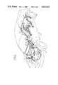
- FIG. 1 is a perspective drawing of a motor vehicle incorporating the present invention. This figure shows the various components of a system embodying the present invention.
- FIG. 2 is an overall system block diagram in accordance with an embodiment of this invention.
- FIGS. 3A and 3B contain a logic flow block diagram in accordance with an embodiment of this invention.
- FIG. 4 is a plan view, partially cut away, of the steering sensor embodying a component of the present invention.
- FIG. 5 is a cross sectional view of the steering sensor of the present invention taken along the line 5--5 of FIG. 4.
- FIG. 6 A illustrates the output wave forms of the detectors employed in the steering sensor illustrated in FIGS. 4 and 5 for clockwise rotation.
- FIG. 6B illustrates the output wave forms of the detectors employed in the steering sensor illustrated in FIGS. 4 and 5 for counterclockwise rotation.
- FIG. 7 is a truth table illustrating the outputs of detectors A and B illustrated in FIGS. 4--6 as the steering sensor of the present invention is rotated counterclockwise and clockwise.
- FIG. 8 is a plan view of a portion of the electromagnetic actuator of this invention.
- FIG. 9 is a cross sectional view of the actuator of the present invention taken along the line 9--9 of FIG. 8.
- FIG. 10 is a partial diagrammatic plan view of the actuator of the present invention, taken along the line 10--10 of FIG. 9, showing the feedback switch with particularity.
- FIG. 11 is similar to FIG. 10 but shows additional details of the armature and feedback switch.
- FIG. 12 is a perspective view of the armature used in the actuator of the present invention.
- the control system of the present invention is intended for use with adjustable suspension units typically found in automotive vehicles.
- Motor vehicle 2 is equipped in conventional fashion with adjustable front struts 4, and rear shock absorbers 6.
- the front struts help to control the attitude of the front of the vehicle while rear shock absorbers 6 help to control the attitude of the rear of the vehicle.
- the adjustable structs 4 and shock absorbers 6 are preferably constructed in a known manner such as disclosed in U.S. Pat. No. 4,313,529 which discloses a means for constructing a strut or shock which is adjustable by a rotary valve positioned within one of the passageways running through the piston. The rotary valve functions to vary the effective cross sectional area of the passageway thus providing an adjustable damping force.
- actuators 5 and 8 are shown as being attached to the uppermost portion of front struts 4 and rear shock absorbers 6.
- the construction of front actuators 5 and rear actuators 8 is shown in detail in FIGS. 8 and 9 and will be discussed at length in this specification.
- FIG. 1 represents merely one preferred embodiment of the present invention, it being understood that this invention is suitable for use with other suspension units such as air or air/hydraulic or hydraulic load-bearing units or combination load bearing and damping units such as those known in the art.
- This system could be employed in conjunction with known variable stabilizer bar units as well.
- the present invention could be applied preferentially to the suspension units located at only one end of the vehicle such as the front or rear.
- suspension control module 14 which receives inputs from each of the actuators mounted upon the suspension units as well as inputs from engine control module 16, steering sensor 18, brake sensor 20, speed sensor 22, and mode selector switch 24.
- the power to operate the system is supplied by the vehicle's main battery 27.
- Engine control module 16 provides an acceleration signal to the suspension control module 14. The purpose of this signal is to notify the suspension control module that the vehicle is in an accleration mode of operation.
- the acceleration signal from engine control module 16 may be triggered by wide open throttle operation, as measured by a throttle position sensor, or by measurement of intake manifold absolute pressure, or by some other type of engine sensor.
- an acceleration signal could be obtained by use of an accelerometer. Usage of a conventional accelerometer would not be entirely satisfactory, however, inasmuch as such devices merely respond to the presence of acceleration and, unlike an engine parameter device, cannot anticipate accleration.
- a vehicle accleration signal could be supplied by a throttle position sensor not operatively associated with an electronic engine control.
- brake sensor 20 which preferably comprises wither a pressure activated switch capable of sensing pressure within the brake lines leading from the brake system's master cylinder (not shown) to each wheel cylinder (not shown).
- brake sensor 20 could comprise a switch operatively associated with the brake pedal mechanism or any other suitable system for sensing brake operation suggested by this disclosure.
- the engine control module and brake sensor thus comprise means for measuring linear acceleration of the motor vehicle.
- Steering sensor 18 provides the suspension control module with a portion of the information necessary for predicting the lateral acceleration of the vehicle. More specifically, steering sensor 18 includes means for measuring the excursion angle of the steering system from a predetermined center position and means for measuring the angular velocity at which the steering system (e.g., the steering shaft) is being operated. As shown in FIGS. 4 and 5, the steering sensor 18 comprises shutter wheel 28 attached to steering shaft 36 which shaft rotates in unison with the steering wheel as the wheel is turned by the driver of the vehicle. Shutter wheel 28 has a plurality of apertures 30, in this case 40 in number, which apertures serve to trigger the activity of detectors A and B as the shutter wheel is rotated with the steering system of vehicle 2. Because there are 40 apertures contained within shutter wheel 28, the steering sensor provides a signal 80 times during one revolution of the steering wheel and as a result each of the 80 signals or steps indicate 4.5° rotation of the steering system.
- each of detectors A and B includes a light emitting diode (LED) 32 and a paired photo diode 34.
- the combination of the LED and photo diode is used to detect movement of the shutter wheel and hence, the steering system. This is possible because the photo diodes have two states--i.e., they are bistable. A conducting state occurs whenever light from the paired LED passes through an aperture in the shutter wheel and impinges upon the photo diode. The output of the detector circuit then rises to approximately 5 volts. A non-conducting state exists whenever the shutter wheel blocks the transmission of light between the LED and the photo diode. As shown in FIG.
- FIG. 7 is a tabulation of the waveforms shown in FIGS. 6A and 6B in a digital format.
- the appoximately 5 volt maximum output of the detectors is treated as a logical "1", while the zero output state is treated as a logical "0".
- FIG. 7 shows each of the possible logic pair states which could be output by detectors A and B. The pairs are arranged in the order in which they will be received by the suspension control module for both counterclockwise and clockwise rotation. As seen in FIG. 7, clockwise rotation is read from the bottom of the figure to the upper part of the figure with counterclockwise rotation being read from the top of the tabulation to the lower part of the tabulation.
- the output of the detectors is further processed by the suspension control module to yield a signal indicative of the steering system's speed or angular velocity.
- This operation is performed quite simply by merely tracking the number of transitions of one or both detectors during a given unit of time. The number of such transitions during the sampling period will be directly proportional to the angular speed of the steering system.
- the steering sensor and suspension control moduel function in combination as a centering means for dynamically determining a center position of the steering system of the motor vehicle by operating according to a method generally comprising the steps of:
- steps b, c and d recited above is repeated until the determined initial center position does not change.
- the repetitions are conducted with threholds defining successively smaller magnitudes of circumferential displacement from the initial center position. It has been determined that initial thresholds having a magnitude of 16 steps of 4.5° clockwise and 16 steps of 4.5° counterclockwise from the initial center provide satisfactory results.
- These thresholds are modified and utilized as follows to dynamically determine a center position according to the following specific steps:
- the excursion angle of the steering system from the predetermined center position may readily be measured by merely performing an algebraic substraction of the current position from the calculated center position at any particular point in time. This measured excursion angle may then be used in the calculation of predicted lateral acceleration of the motor vehicle.
- Most, if not all, prior art steering center position sensors require precise positioning of the sensor's componentry in order to permit satisfactory operation of the sensor. This requirement could be expected to lead to inaccurate sensing if the sensor were assembled improperly during the production process or in the event that the sensor's position changed for any reason following installation.
- the steering sensor of the present invention stands in marked contrast because it requires no prepositioning of any sort upon installation and subsequent changes in its position will have absolutely no effect on the sensor's function.
- Speed sensor 22 (FIGS. 1 and 2) provides yet another input to suspension control module 14.
- the speed sensor preferably comprises a magnetic pickup operatively associated with the transmission, or some other portion of the drive train such as a drive shaft or axle shaft.
- speed of the vehicle could be sensed by any of a variety of means including not only those means which rely upon measurement of rotational speed of a drive train component, but also ground speed measuring means relying upon such methods as radar, sonar, etc.
- mode selector switch 24 allows the driver of the motor vehicle to select “automatic” or “hard” settings for the adjustable suspension units. Such selection by the driver comprises yet another input to the suspension control module.
- Mode indicator light 26 advises the driver of the motor vehicle as to which of the predetermined operating states the suspension units of the vehicle are resting in.
- FIG. 2 shows each of the input devices associated with the suspension control module as well as the actuators operatively associated with the control module. As shown in FIG. 2, actuators 5 and 8 send information to the control module and receive commands from the control module. Information sent to the control module is provided by the feedback circuitry contained within the actuators.
- FIGS. 8-12 illustrate the construction of the actuator assemblies.
- an electromechanical actuator is disclosed, it will be appreciated by those skilled in the art in view of this disclosure that the actuators could comprise pneumatic, vacuum, hydraulic or, gear motor driven units. It will be further appreciated by those skilled in the art that although the actuators disclosed herein are bistable, the present invention is suitable for use with suspension units having a plurality of predetermined stable operating states.
- an actuator suitable for use with the present invention comprises armature 42 having winding 44 which is connected to brushes 46.
- the brushes allow current to pass through the armature in desired fashion so as to select the armature's rotational position within the actuator.
- Permanent magnets 45 are located about the periphery of the armature.
- the armature has two stable states it may occupy. These states are rotationally limited by stops 53a and 53b which are engaged by stop striker 55 mounted to the armature. When the armature is energized, it will rotate until striker 55 contacts either of the two stops. The particular direction of rotation is determined by the direction of current flow through the armature which is in turn determined by the suspension control module.
- Armature 42 is equipped with a central bearing 48 which rotates upon pinion 50 which is fixed to the case of the actuator.
- Bearing 48 has an axial slot 52 at one end. This slot engages a tang formed on control rod 54 which runs down through the controlled shock absorber or suspension strut so as to control the shock absorber or strut in accord with U.S. Pat. No. 4,313,529.
- the actuator comprises a bistable control mechanism for the shock absorber or strut.
- a feedback feature is provided by a position contact set contained within the actuator.
- Movable contact 56 and stationary contact 58 are arranged within the actuator housing such that the contacts will be closed by striker 60 when the actuator is in one of its two stable states.
- the contact set thus provides feedback to the suspension control module regarding the particular state in which the actuator and suspension unit are resting.
- This is advantageous because it has been found that certain bistable shock absorbers and McPherson struts of the general type described in U.S. Pat. No. 4,313,529 will spontaneously change from one stable state to another under the influence of driving forces, even in the absence of a command signal to the actuator. Accordingly, in the absence of a feedback circuit one or more suspension units could be in an incorrect position; without the feedback feature, the suspension control module would not have the information that the suspension units were in the incorrect position. As a result, the suspension control module would not be able to correct the improper state.
- Block 62 evaluates the acceleration of the vehicle, whether the acceleration signal originates from acceleration sensor 16 or brake sensor 20. In the event that acceleration or deceleration are of sufficient magnitude, the accel/decel flag within the computer will be set to the hard position; if neither the acceleration or deceleration are of sufficient magnitude, the accel/decel flag will be set soft.
- the accleration sensor is calibrated to detect wide open throttle (WOT) accleration and the brake sensor is set to detect brake line pressure sufficient to produce a 0.3G deceleration, but other levels of throttle opening positions and deceleration rate could be used to trigger the accel/decel flat.
- WOT wide open throttle
- the term flag merely refers to a register employed as an electronic notebook to keep track of the presence of various triggering levels of the logic variables used to determine which of the stable states the suspension units are to be operated.
- the vehicle's speed sensor output is read; if vehicle speed is less than 74 miles per hour block 65 sets the speed flag in the soft position. In the event that vehicle speed exceeds 83 miles per hour block 63 sets the speed flag in the hard position and then proceeds to block 66. In the event that vehicle speed is between 74 and 83 miles per hour the strategy proceeds directly to block 66 where the current steering position is read. Block 66 may also be reached through block 67, which inquires whether the vehicle speed is above 15 miles per hour. If the vehicle's speed is greater than 15 miles per hour the strategy proceeds to block 66 to read the current steering position. If vehicle speed is not above 15 miles per hour the strategy proceeds to block 73 wherein the steering flag is set to the soft position.
- block 69 inquires into the need for revising the steering center reference. If the reference should be revised the logic flow proceeds to block 68 wherein this command is given. If the steering center reference is not in need of revision the logic proceeds to block 70 wherein an inquiry is made to the accuracy of the steering reference.
- the steering reference in this case merely means the previously discussed center position for the steering system and blocks 68, 69 and 70 symbolically refer to the logic embodied in the previously disclosed method for dynamically determined the center position of the steering system.
- block 72 calculates vehicle lateral acceleration. This acceleration may be calculated by either of two methods.
- the first method comprises simple calculation of the product of the square of the vehicle's speed and the excursion angle of the steering system from the predetermined center position.
- the expression of this calculation has the following form:
- V 2 the square of the vehicle's speed
- ⁇ the excursion angle of the steering system from the predetermined center position.
- V 2 the square of the vehicle's speed
- ⁇ the magnitude of the excursion angle of the steering system from the predetermined center position
- W 2 the square of steering system angular velocity
- C a constant having a positive value in the event that the steering system is moving in a direction so as to increase ⁇ and a negative value in the event that the steering system is moving in a direction so as to decrease ⁇ .
- the second expression set forth above is more comprehensive than the first because it includes the additional term W 2 C, which accounts for the fact that the instantaneous steering system excursion angle will be further changed by the driver's rotation of the steering wheel in those situations wherein the steering system is being operated at an angular speed greater than zero at the time the excursion angle is measured.
- the constant "C" corresponds to an assumed maximum deceleration rate for the steering system which could be produced by a human operator.
- the previously defined expressions for calculating predicted lateral acceleration allow the suspension control module to deliver a command to the actuators calling for a hard setting in advance of the actual onset of lateral acceleration of the vehicle. This is true because the vehicle will not go into a turn resulting in lateral acceleration until a small but finite time period after the steering system angle changes.
- the system of the present invention thus offers a significant advantage over prior art systems relying upon acclerometers to sense lateral acceleration, particularly where those systems are combined with passive devices in the nature of conventional shock absorbers which are unable to exert any restoring forces upon the vehicle suspension.
- the logic examines the magnitude of the predicted acceleration. If the lateral acceleration is predicted as being less than 0.3G, the steering flag is set soft in block 73. If the predicted lateral acceleration is greater than or equal to 0.3G, the steering flag is set hard in block 71.
- the threshold values for lateral acceleration recited herein may be modified to suit particular needs of the vehicle and the driver. From either blocks 71 or 73, the logic flow proceeds to block 74 wherein the position of the mode selector switch is read. In the event that the driver placed the switch in the firm position, the actuation routine requests the hard shock absorber setting in block 75.
- block 76 asks whether any of the 3 flags is in the hard position. In the event that at least one flag is in the hard position, block 75 requests the hard suspension unit setting. If none of the flags is in the hard position, the logic proceeds to block 77 wherein the amount of time each of the flags has been in the soft position is noted.
- the actuation routine at block 78 requests the soft setting for the suspension unit.
- the actuation routine in block 79 makes no new request. From this point the logic continues to block 62 to be rerun throughout the vehicle operation.
Landscapes
- Engineering & Computer Science (AREA)
- Mechanical Engineering (AREA)
- Chemical & Material Sciences (AREA)
- Combustion & Propulsion (AREA)
- Transportation (AREA)
- Vehicle Body Suspensions (AREA)
Priority Applications (6)
| Application Number | Priority Date | Filing Date | Title |
|---|---|---|---|
| US06/809,672 US4621833A (en) | 1985-12-16 | 1985-12-16 | Control system for multistable suspension unit |
| CA000521372A CA1242510A (en) | 1985-12-16 | 1986-10-24 | Control system for multistable suspension unit |
| DE8686309405T DE3684116D1 (de) | 1985-12-16 | 1986-12-03 | Steuerung fuer eine einstellbare radaufhaengung. |
| EP86309405A EP0227343B2 (de) | 1985-12-16 | 1986-12-03 | Steuerung für eine einstellbare Radaufhängung |
| JP61298586A JPH0764177B2 (ja) | 1985-12-16 | 1986-12-15 | 多重安定性サスペンシヨン・ユニツトの操作システム |
| AU66539/86A AU583230B2 (en) | 1985-12-16 | 1986-12-15 | Control system for multistable suspension unit |
Applications Claiming Priority (1)
| Application Number | Priority Date | Filing Date | Title |
|---|---|---|---|
| US06/809,672 US4621833A (en) | 1985-12-16 | 1985-12-16 | Control system for multistable suspension unit |
Publications (1)
| Publication Number | Publication Date |
|---|---|
| US4621833A true US4621833A (en) | 1986-11-11 |
Family
ID=25201946
Family Applications (1)
| Application Number | Title | Priority Date | Filing Date |
|---|---|---|---|
| US06/809,672 Expired - Lifetime US4621833A (en) | 1985-12-16 | 1985-12-16 | Control system for multistable suspension unit |
Country Status (6)
| Country | Link |
|---|---|
| US (1) | US4621833A (de) |
| EP (1) | EP0227343B2 (de) |
| JP (1) | JPH0764177B2 (de) |
| AU (1) | AU583230B2 (de) |
| CA (1) | CA1242510A (de) |
| DE (1) | DE3684116D1 (de) |
Cited By (61)
| Publication number | Priority date | Publication date | Assignee | Title |
|---|---|---|---|---|
| US4722545A (en) * | 1987-05-04 | 1988-02-02 | Ford Motor Company | Method and apparatus for determining the center position of a vehicular steering system |
| US4747055A (en) * | 1985-03-27 | 1988-05-24 | Toyoda Koki Kabushiki Kaisha | Driving status discrimination device for a motor vehicle |
| WO1989000927A1 (en) * | 1987-07-28 | 1989-02-09 | Mitsubishi Jidosha Kogyo Kabushiki Kaisha | Control apparatus for a vehicular suspension system |
| US4805923A (en) * | 1987-12-16 | 1989-02-21 | Ford Motor Company | Adaptive control system for operating adjustable automotive suspension units |
| US4809179A (en) * | 1987-01-20 | 1989-02-28 | Ford Motor Company | Control system for motor vehicle suspension unit |
| US4809183A (en) * | 1986-03-01 | 1989-02-28 | Robert Bosch Gmbh | Speed control system for motor vehicles operating in a curved path |
| US4834419A (en) * | 1986-10-16 | 1989-05-30 | Nippondenso Co., Ltd. | Hydraulic stabilizer control system with road surface sensor |
| US4848791A (en) * | 1988-01-06 | 1989-07-18 | Ford Motor Company | Method and apparatus for determining steering position of automotive steering mechanism |
| US4853860A (en) * | 1987-11-18 | 1989-08-01 | Ford Motor Company | Control system for adjustable automotive suspension unit |
| US4856607A (en) * | 1987-04-07 | 1989-08-15 | Tokai Trw & Co., Ltd. | Apparatus for automatically setting steering center for use in power steering apparatus |
| US4865347A (en) * | 1987-03-16 | 1989-09-12 | Nissan Motor Company, Limited | Actively controlled suspension system with anti-roll control |
| US4867466A (en) * | 1987-12-16 | 1989-09-19 | Ford Motor Company | Distance based method and apparatus for determining the center position of a vehicular steering system |
| US4869528A (en) * | 1987-05-12 | 1989-09-26 | Toyota Jidosha Kabushiki Kaisha | Electronically controlled fluid suspension system |
| US4882693A (en) * | 1987-12-28 | 1989-11-21 | Ford Motor Company | Automotive system for dynamically determining road adhesion |
| US4905783A (en) * | 1987-06-26 | 1990-03-06 | Ford Motor Company | Vehicular controller with differential wheel speed input |
| US4911470A (en) * | 1988-03-31 | 1990-03-27 | Nissan Motor Company, Limited | Hydraulic circuit for actively controlled automotive suspension system |
| US4944356A (en) * | 1988-12-28 | 1990-07-31 | Ford Motor Company | Steering system position detector |
| US4971353A (en) * | 1988-11-10 | 1990-11-20 | Toyota Jidosha Kabushiki Kaisha | Hydraulic suspension system for a vehicle |
| US4970906A (en) * | 1986-01-14 | 1990-11-20 | Koito Manufacturing Co., Ltd. | Method and apparatus for determining a rotation center of a rotary body |
| US4999776A (en) * | 1989-11-30 | 1991-03-12 | Ford Motor Company | Method and apparatus for determining the center position of a vehicular steering system |
| US5004264A (en) * | 1988-07-29 | 1991-04-02 | Nippondenso Co., Ltd. | Position control device and automotive suspension system employing same |
| US5016907A (en) * | 1988-07-29 | 1991-05-21 | Nissan Motor Company, Limited | Anti-rolling control system for automotive active suspension system |
| US5120982A (en) * | 1989-11-14 | 1992-06-09 | Ford Motor Company | Fault correcting circuit |
| US5144558A (en) * | 1986-06-13 | 1992-09-01 | Nissan Motor Company, Limited | Actively controlled automotive suspension system with adjustable rolling-stability and/or pitching-stability |
| FR2680139A1 (fr) * | 1991-08-07 | 1993-02-12 | Fichtel & Sachs Ag | Dispositif pour influencer un composant de vehicule en fonction de l'acceleration transversale. |
| US5243324A (en) * | 1991-11-07 | 1993-09-07 | Ford Motor Company | Method of detecting a fault in an automotive system |
| US5294757A (en) * | 1990-07-18 | 1994-03-15 | Otis Elevator Company | Active vibration control system for an elevator, which reduces horizontal and rotational forces acting on the car |
| US5304751A (en) * | 1991-07-16 | 1994-04-19 | Otis Elevator Company | Elevator horizontal suspensions and controls |
| US5308938A (en) * | 1990-07-18 | 1994-05-03 | Otis Elevator Company | Elevator active suspension system |
| US5321217A (en) * | 1990-07-18 | 1994-06-14 | Otis Elevator Company | Apparatus and method for controlling an elevator horizontal suspension |
| US5322144A (en) * | 1990-07-18 | 1994-06-21 | Otis Elevator Company | Active control of elevator platform |
| US5369583A (en) * | 1992-02-12 | 1994-11-29 | Lucas Industries Public Limited Company | Optical torque sensors and steering systems for vehicles incorporating them |
| US5384705A (en) * | 1991-01-14 | 1995-01-24 | Toyota Jidosha Kabushiki Kaisha | Active suspension with roll control by reducibly modified estimated transverse acceleration |
| US5400872A (en) * | 1990-07-18 | 1995-03-28 | Otis Elevator Company | Counteracting horizontal accelerations on an elevator car |
| US5422810A (en) * | 1994-05-05 | 1995-06-06 | Ford Motor Company | Method and apparatus for determining steering position of automotive steering mechanism |
| US5524730A (en) * | 1991-03-13 | 1996-06-11 | Otis Elevator Company | Method and apparatus for storing sensed elevator horizontal displacement and acceleration signals |
| US5531127A (en) * | 1993-08-13 | 1996-07-02 | Lucas Industries Public Limited Company | Optical torque sensor |
| US5544721A (en) * | 1991-03-13 | 1996-08-13 | Otis Elevator Company | Method and apparatus for adjusting an elevator car based on stored horizontal displacement and acceleration information |
| US5632503A (en) * | 1995-12-19 | 1997-05-27 | Ford Motor Company | Method for allowing enhanced driver selection of suspension damping and steering efforts |
| US5696678A (en) * | 1995-12-19 | 1997-12-09 | Ford Global Technologies, Inc. | Method for preventing undesirable lowering of an air suspension system |
| US5732372A (en) * | 1995-06-09 | 1998-03-24 | Ford Global Technologies, Inc. | Method for determining a center position of a vehicle steering system |
| EP1018464A2 (de) | 1999-01-05 | 2000-07-12 | Ford Global Technologies, Inc. | Verfahren und Vorrichtung für eine Servolenkung mit veränderlicher Unterstützung |
| EP1018465A2 (de) | 1999-01-05 | 2000-07-12 | Ford Global Technologies, Inc. | Lenkungssteuerverfahren für eine Servolenkung mit variabler Unterstützung |
| US6089344A (en) * | 1998-06-01 | 2000-07-18 | Ford Global Technologies, Inc. | Method and apparatus for determining the center position of a steering system |
| US6494471B2 (en) | 2001-01-09 | 2002-12-17 | New Holland North America, Inc. | Apparatus for sensing an angular position of a wheel of a vehicle about a steering axis |
| US20040024565A1 (en) * | 2002-08-05 | 2004-02-05 | Jingsheng Yu | Vehicle operating parameter determination system and method |
| US20040133326A1 (en) * | 2003-01-03 | 2004-07-08 | Ghoneim Youssef Ahmed | Method and apparatus for vehicle integrated chassis control system |
| US6789017B2 (en) | 2002-02-15 | 2004-09-07 | Robert Bosch Corporation | Vehicle steering angle position determination method |
| US20040256831A1 (en) * | 2001-02-22 | 2004-12-23 | Sharp Keith Leslie | Vehicle suspension |
| USRE39011E1 (en) | 1994-03-31 | 2006-03-14 | Cattron Intellectual Property Corporation | Remote control system for a locomotive |
| US20060287791A1 (en) * | 2005-06-21 | 2006-12-21 | Tenneco Automotive Operating Company, Inc. | Semi-active anti-roll system |
| US20070265749A1 (en) * | 2006-05-09 | 2007-11-15 | Lockheed Martin Corporation | Mobility traction control system and method |
| US7314221B1 (en) | 2004-08-23 | 2008-01-01 | Clifford Everlith | Driver controlled wedge and track bar adjustors |
| US20120046834A1 (en) * | 2010-08-18 | 2012-02-23 | Messier-Bugatti-Dowty | Method of controlling the yawing movement of an aircraft running along the ground |
| US8145402B2 (en) | 2007-12-05 | 2012-03-27 | Lockheed Martin Corporation | GPS-based traction control system and method using data transmitted between vehicles |
| US8229639B2 (en) | 2009-02-17 | 2012-07-24 | Lockheed Martin Corporation | System and method for stability control |
| US8244442B2 (en) | 2009-02-17 | 2012-08-14 | Lockheed Martin Corporation | System and method for stability control of vehicle and trailer |
| US8352120B2 (en) | 2009-02-17 | 2013-01-08 | Lockheed Martin Corporation | System and method for stability control using GPS data |
| US20130079996A1 (en) * | 2011-03-29 | 2013-03-28 | Jaguar Cars Limited | Control of active vehicle devices during cornering |
| US8589049B2 (en) | 2007-12-03 | 2013-11-19 | Lockheed Martin Corporation | GPS-based system and method for controlling vehicle characteristics based on terrain |
| CN113002619A (zh) * | 2019-12-20 | 2021-06-22 | 现代自动车株式会社 | 用于控制后车轮转向的装置及方法 |
Families Citing this family (5)
| Publication number | Priority date | Publication date | Assignee | Title |
|---|---|---|---|---|
| DE3903359A1 (de) * | 1989-02-05 | 1990-08-09 | Bayerische Motoren Werke Ag | Einrichtung zur bestimmung des lenkraddrehwinkels eines kraftfahrzeuges |
| KR930009380B1 (ko) * | 1989-05-29 | 1993-10-02 | 미쓰비시덴키 가부시키가이샤 | 현가제어장치 |
| JP3080274B2 (ja) * | 1992-09-16 | 2000-08-21 | 株式会社ユニシアジェックス | 車両懸架装置 |
| GB9321056D0 (en) * | 1993-10-08 | 1993-12-01 | Acg France | Vehicle damping system |
| DE4337766C1 (de) * | 1993-11-05 | 1994-12-15 | Fichtel & Sachs Ag | Verfahren und Einrichtung zur Bereitstellung eines Querbeschleunigungssignals für die Ansteuerung eines verstellbaren Fahrwerksystems |
Citations (20)
| Publication number | Priority date | Publication date | Assignee | Title |
|---|---|---|---|---|
| US1930317A (en) * | 1931-12-14 | 1933-10-10 | Delco Prod Corp | Shock absorber |
| US2140767A (en) * | 1935-11-21 | 1938-12-20 | Bendix Prod Corp | Shock absorber control mechanism |
| US2698068A (en) * | 1950-11-10 | 1954-12-28 | Frank J Hein | Vehicle dive arrester |
| US3146862A (en) * | 1960-09-21 | 1964-09-01 | Daimler Benz Ag | Remote controlled fluid-shockabsorber for vehicles |
| US3537715A (en) * | 1968-02-19 | 1970-11-03 | Robert R Gualdoni | Snubbing means for automotive vehicle |
| US3548977A (en) * | 1966-11-09 | 1970-12-22 | Frank S Morgan | Shock absorbers |
| US3608925A (en) * | 1969-05-07 | 1971-09-28 | Peter H Murphy | Apparatus for offsetting centrifugal force affecting motor vehicles |
| US3861696A (en) * | 1972-06-01 | 1975-01-21 | Bofors Ab | Device for damping rocking movements occurring in a chassis |
| US3895816A (en) * | 1973-03-12 | 1975-07-22 | Honda Motor Co Ltd | Vehicle-attitude control device |
| US3913938A (en) * | 1973-07-04 | 1975-10-21 | Nissan Motor | Self-levelling vehicle suspension system |
| US4313529A (en) * | 1978-11-10 | 1982-02-02 | Tokico Ltd. | Hydraulic damper |
| US4333668A (en) * | 1979-12-17 | 1982-06-08 | The Bendix Corporation | Electronic adaptive ride control system |
| US4345661A (en) * | 1978-06-08 | 1982-08-24 | Honda Giken Kogyo Kabushiki Kaisha | Anti-roll system for vehicles |
| US4361346A (en) * | 1980-01-26 | 1982-11-30 | Lucas Industries Limited | Suspension systems for vehicles |
| US4371191A (en) * | 1977-08-22 | 1983-02-01 | Springhill Laboratories, Inc. | Adjusting automobile suspension system |
| US4468050A (en) * | 1983-08-15 | 1984-08-28 | Woods Lonnie K | Computer optimized adaptive suspension system |
| US4519627A (en) * | 1982-06-07 | 1985-05-28 | Nissan Motor Co., Ltd. | Automative compliance steering control supension |
| US4526401A (en) * | 1982-11-30 | 1985-07-02 | Atsugi Motor Parts Co., Ltd. | Electronic control system for adjustable shock absorbers |
| US4575116A (en) * | 1982-12-27 | 1986-03-11 | Toyota Jidosha Kabushiki Kaisha | Shock absorber control unit for use of a vehicle suspension |
| US4586728A (en) * | 1983-02-28 | 1986-05-06 | Mazda Motor Corporation | Vehicle suspension means having variable suspension characteristics |
Family Cites Families (5)
| Publication number | Priority date | Publication date | Assignee | Title |
|---|---|---|---|---|
| DE2736026C2 (de) * | 1976-08-19 | 1985-10-24 | Honda Giken Kogyo K.K., Tokio/Tokyo | Hydropneumatische Federung für Fahrzeuge |
| US4555126A (en) * | 1982-10-18 | 1985-11-26 | Mazda Motor Corporation | Vehicle suspension system |
| EP0115202B1 (de) * | 1982-12-27 | 1988-03-02 | Nippondenso Co., Ltd. | System zum Steuern eines Stossdämpfers |
| JPS60128011A (ja) † | 1983-12-12 | 1985-07-08 | Nissan Motor Co Ltd | 車両におけるロ−ル剛性制御装置 |
| JPS60203510A (ja) † | 1984-03-27 | 1985-10-15 | Mitsubishi Motors Corp | 自動車の懸架装置 |
-
1985
- 1985-12-16 US US06/809,672 patent/US4621833A/en not_active Expired - Lifetime
-
1986
- 1986-10-24 CA CA000521372A patent/CA1242510A/en not_active Expired
- 1986-12-03 EP EP86309405A patent/EP0227343B2/de not_active Expired - Lifetime
- 1986-12-03 DE DE8686309405T patent/DE3684116D1/de not_active Expired - Lifetime
- 1986-12-15 AU AU66539/86A patent/AU583230B2/en not_active Ceased
- 1986-12-15 JP JP61298586A patent/JPH0764177B2/ja not_active Expired - Fee Related
Patent Citations (20)
| Publication number | Priority date | Publication date | Assignee | Title |
|---|---|---|---|---|
| US1930317A (en) * | 1931-12-14 | 1933-10-10 | Delco Prod Corp | Shock absorber |
| US2140767A (en) * | 1935-11-21 | 1938-12-20 | Bendix Prod Corp | Shock absorber control mechanism |
| US2698068A (en) * | 1950-11-10 | 1954-12-28 | Frank J Hein | Vehicle dive arrester |
| US3146862A (en) * | 1960-09-21 | 1964-09-01 | Daimler Benz Ag | Remote controlled fluid-shockabsorber for vehicles |
| US3548977A (en) * | 1966-11-09 | 1970-12-22 | Frank S Morgan | Shock absorbers |
| US3537715A (en) * | 1968-02-19 | 1970-11-03 | Robert R Gualdoni | Snubbing means for automotive vehicle |
| US3608925A (en) * | 1969-05-07 | 1971-09-28 | Peter H Murphy | Apparatus for offsetting centrifugal force affecting motor vehicles |
| US3861696A (en) * | 1972-06-01 | 1975-01-21 | Bofors Ab | Device for damping rocking movements occurring in a chassis |
| US3895816A (en) * | 1973-03-12 | 1975-07-22 | Honda Motor Co Ltd | Vehicle-attitude control device |
| US3913938A (en) * | 1973-07-04 | 1975-10-21 | Nissan Motor | Self-levelling vehicle suspension system |
| US4371191A (en) * | 1977-08-22 | 1983-02-01 | Springhill Laboratories, Inc. | Adjusting automobile suspension system |
| US4345661A (en) * | 1978-06-08 | 1982-08-24 | Honda Giken Kogyo Kabushiki Kaisha | Anti-roll system for vehicles |
| US4313529A (en) * | 1978-11-10 | 1982-02-02 | Tokico Ltd. | Hydraulic damper |
| US4333668A (en) * | 1979-12-17 | 1982-06-08 | The Bendix Corporation | Electronic adaptive ride control system |
| US4361346A (en) * | 1980-01-26 | 1982-11-30 | Lucas Industries Limited | Suspension systems for vehicles |
| US4519627A (en) * | 1982-06-07 | 1985-05-28 | Nissan Motor Co., Ltd. | Automative compliance steering control supension |
| US4526401A (en) * | 1982-11-30 | 1985-07-02 | Atsugi Motor Parts Co., Ltd. | Electronic control system for adjustable shock absorbers |
| US4575116A (en) * | 1982-12-27 | 1986-03-11 | Toyota Jidosha Kabushiki Kaisha | Shock absorber control unit for use of a vehicle suspension |
| US4586728A (en) * | 1983-02-28 | 1986-05-06 | Mazda Motor Corporation | Vehicle suspension means having variable suspension characteristics |
| US4468050A (en) * | 1983-08-15 | 1984-08-28 | Woods Lonnie K | Computer optimized adaptive suspension system |
Cited By (81)
| Publication number | Priority date | Publication date | Assignee | Title |
|---|---|---|---|---|
| US4747055A (en) * | 1985-03-27 | 1988-05-24 | Toyoda Koki Kabushiki Kaisha | Driving status discrimination device for a motor vehicle |
| US4970906A (en) * | 1986-01-14 | 1990-11-20 | Koito Manufacturing Co., Ltd. | Method and apparatus for determining a rotation center of a rotary body |
| US4809183A (en) * | 1986-03-01 | 1989-02-28 | Robert Bosch Gmbh | Speed control system for motor vehicles operating in a curved path |
| US5144558A (en) * | 1986-06-13 | 1992-09-01 | Nissan Motor Company, Limited | Actively controlled automotive suspension system with adjustable rolling-stability and/or pitching-stability |
| US4834419A (en) * | 1986-10-16 | 1989-05-30 | Nippondenso Co., Ltd. | Hydraulic stabilizer control system with road surface sensor |
| US4809179A (en) * | 1987-01-20 | 1989-02-28 | Ford Motor Company | Control system for motor vehicle suspension unit |
| US4865347A (en) * | 1987-03-16 | 1989-09-12 | Nissan Motor Company, Limited | Actively controlled suspension system with anti-roll control |
| US4856607A (en) * | 1987-04-07 | 1989-08-15 | Tokai Trw & Co., Ltd. | Apparatus for automatically setting steering center for use in power steering apparatus |
| US4722545A (en) * | 1987-05-04 | 1988-02-02 | Ford Motor Company | Method and apparatus for determining the center position of a vehicular steering system |
| US4869528A (en) * | 1987-05-12 | 1989-09-26 | Toyota Jidosha Kabushiki Kaisha | Electronically controlled fluid suspension system |
| US4905783A (en) * | 1987-06-26 | 1990-03-06 | Ford Motor Company | Vehicular controller with differential wheel speed input |
| WO1989000927A1 (en) * | 1987-07-28 | 1989-02-09 | Mitsubishi Jidosha Kogyo Kabushiki Kaisha | Control apparatus for a vehicular suspension system |
| US4930082A (en) * | 1987-07-28 | 1990-05-29 | Mitsubishi Jidosha Kogyo Kabushiki Kaisha | Control apparatus for a vehicular suspension system |
| US4853860A (en) * | 1987-11-18 | 1989-08-01 | Ford Motor Company | Control system for adjustable automotive suspension unit |
| EP0317071A3 (en) * | 1987-11-18 | 1990-10-03 | Ford Motor Company Limited | Control system for adjustable automotive suspension unit |
| US4867466A (en) * | 1987-12-16 | 1989-09-19 | Ford Motor Company | Distance based method and apparatus for determining the center position of a vehicular steering system |
| US4805923A (en) * | 1987-12-16 | 1989-02-21 | Ford Motor Company | Adaptive control system for operating adjustable automotive suspension units |
| EP0321082A3 (en) * | 1987-12-16 | 1990-10-17 | Ford Motor Company Limited | Method and apparatus for determining the center position of a vehicular steering system |
| US4882693A (en) * | 1987-12-28 | 1989-11-21 | Ford Motor Company | Automotive system for dynamically determining road adhesion |
| EP0323899A3 (en) * | 1988-01-06 | 1990-10-03 | Ford Motor Company Limited | Method and apparatus for determining steering position of automotive steering mechanism |
| US4848791A (en) * | 1988-01-06 | 1989-07-18 | Ford Motor Company | Method and apparatus for determining steering position of automotive steering mechanism |
| US4911470A (en) * | 1988-03-31 | 1990-03-27 | Nissan Motor Company, Limited | Hydraulic circuit for actively controlled automotive suspension system |
| US5004264A (en) * | 1988-07-29 | 1991-04-02 | Nippondenso Co., Ltd. | Position control device and automotive suspension system employing same |
| US5016907A (en) * | 1988-07-29 | 1991-05-21 | Nissan Motor Company, Limited | Anti-rolling control system for automotive active suspension system |
| US4971353A (en) * | 1988-11-10 | 1990-11-20 | Toyota Jidosha Kabushiki Kaisha | Hydraulic suspension system for a vehicle |
| US4944356A (en) * | 1988-12-28 | 1990-07-31 | Ford Motor Company | Steering system position detector |
| US5120982A (en) * | 1989-11-14 | 1992-06-09 | Ford Motor Company | Fault correcting circuit |
| US4999776A (en) * | 1989-11-30 | 1991-03-12 | Ford Motor Company | Method and apparatus for determining the center position of a vehicular steering system |
| US5439075A (en) * | 1990-07-18 | 1995-08-08 | Otis Elevator Company | Elevator active suspension system |
| US5294757A (en) * | 1990-07-18 | 1994-03-15 | Otis Elevator Company | Active vibration control system for an elevator, which reduces horizontal and rotational forces acting on the car |
| US5400872A (en) * | 1990-07-18 | 1995-03-28 | Otis Elevator Company | Counteracting horizontal accelerations on an elevator car |
| US5308938A (en) * | 1990-07-18 | 1994-05-03 | Otis Elevator Company | Elevator active suspension system |
| US5321217A (en) * | 1990-07-18 | 1994-06-14 | Otis Elevator Company | Apparatus and method for controlling an elevator horizontal suspension |
| US5322144A (en) * | 1990-07-18 | 1994-06-21 | Otis Elevator Company | Active control of elevator platform |
| US5384705A (en) * | 1991-01-14 | 1995-01-24 | Toyota Jidosha Kabushiki Kaisha | Active suspension with roll control by reducibly modified estimated transverse acceleration |
| US5524730A (en) * | 1991-03-13 | 1996-06-11 | Otis Elevator Company | Method and apparatus for storing sensed elevator horizontal displacement and acceleration signals |
| US5544721A (en) * | 1991-03-13 | 1996-08-13 | Otis Elevator Company | Method and apparatus for adjusting an elevator car based on stored horizontal displacement and acceleration information |
| US5304751A (en) * | 1991-07-16 | 1994-04-19 | Otis Elevator Company | Elevator horizontal suspensions and controls |
| FR2680139A1 (fr) * | 1991-08-07 | 1993-02-12 | Fichtel & Sachs Ag | Dispositif pour influencer un composant de vehicule en fonction de l'acceleration transversale. |
| US5381335A (en) * | 1991-08-07 | 1995-01-10 | Fichtel & Sachs Ag | Device for controlling a vehicle component in dependence upon transverse acceleration |
| US5243324A (en) * | 1991-11-07 | 1993-09-07 | Ford Motor Company | Method of detecting a fault in an automotive system |
| US5369583A (en) * | 1992-02-12 | 1994-11-29 | Lucas Industries Public Limited Company | Optical torque sensors and steering systems for vehicles incorporating them |
| US5531127A (en) * | 1993-08-13 | 1996-07-02 | Lucas Industries Public Limited Company | Optical torque sensor |
| USRE39758E1 (en) | 1994-03-31 | 2007-08-07 | Cattron Intellectual Property Corporation | Remote control system for a locomotive |
| USRE39011E1 (en) | 1994-03-31 | 2006-03-14 | Cattron Intellectual Property Corporation | Remote control system for a locomotive |
| USRE39210E1 (en) | 1994-03-31 | 2006-08-01 | Cattron Intellectual Property Corporation | Remote control system for a locomotive |
| US5422810A (en) * | 1994-05-05 | 1995-06-06 | Ford Motor Company | Method and apparatus for determining steering position of automotive steering mechanism |
| US5732372A (en) * | 1995-06-09 | 1998-03-24 | Ford Global Technologies, Inc. | Method for determining a center position of a vehicle steering system |
| US5696678A (en) * | 1995-12-19 | 1997-12-09 | Ford Global Technologies, Inc. | Method for preventing undesirable lowering of an air suspension system |
| US5632503A (en) * | 1995-12-19 | 1997-05-27 | Ford Motor Company | Method for allowing enhanced driver selection of suspension damping and steering efforts |
| US6089344A (en) * | 1998-06-01 | 2000-07-18 | Ford Global Technologies, Inc. | Method and apparatus for determining the center position of a steering system |
| EP1018465A2 (de) | 1999-01-05 | 2000-07-12 | Ford Global Technologies, Inc. | Lenkungssteuerverfahren für eine Servolenkung mit variabler Unterstützung |
| US6167334A (en) * | 1999-01-05 | 2000-12-26 | Ford Global Technologies, Inc. | Method and apparatus for providing variable assist power steering |
| US6173223B1 (en) * | 1999-01-05 | 2001-01-09 | Ford Global Technologies, Inc. | Steering control method for providing variable assist power steering |
| EP1018464A2 (de) | 1999-01-05 | 2000-07-12 | Ford Global Technologies, Inc. | Verfahren und Vorrichtung für eine Servolenkung mit veränderlicher Unterstützung |
| US6494471B2 (en) | 2001-01-09 | 2002-12-17 | New Holland North America, Inc. | Apparatus for sensing an angular position of a wheel of a vehicle about a steering axis |
| US20040256831A1 (en) * | 2001-02-22 | 2004-12-23 | Sharp Keith Leslie | Vehicle suspension |
| US6789017B2 (en) | 2002-02-15 | 2004-09-07 | Robert Bosch Corporation | Vehicle steering angle position determination method |
| US6816799B2 (en) | 2002-08-05 | 2004-11-09 | Robert Bosch Corporation | Vehicle operating parameter determination system and method |
| US20040024565A1 (en) * | 2002-08-05 | 2004-02-05 | Jingsheng Yu | Vehicle operating parameter determination system and method |
| US6879898B2 (en) | 2003-01-03 | 2005-04-12 | General Motors Corporation | Method and apparatus for vehicle integrated chassis control system |
| EP1445130A1 (de) * | 2003-01-03 | 2004-08-11 | General Motors Corporation | Verfahren und Vorrichtung zur Fahrwerkregelung eines Kraftfahrzeuges |
| US20040133326A1 (en) * | 2003-01-03 | 2004-07-08 | Ghoneim Youssef Ahmed | Method and apparatus for vehicle integrated chassis control system |
| US7314221B1 (en) | 2004-08-23 | 2008-01-01 | Clifford Everlith | Driver controlled wedge and track bar adjustors |
| US20060287791A1 (en) * | 2005-06-21 | 2006-12-21 | Tenneco Automotive Operating Company, Inc. | Semi-active anti-roll system |
| US7751959B2 (en) * | 2005-06-21 | 2010-07-06 | Tenneco Automotive Operating Company Inc. | Semi-active suspension system with anti-roll for a vehicle |
| US20070265749A1 (en) * | 2006-05-09 | 2007-11-15 | Lockheed Martin Corporation | Mobility traction control system and method |
| US7577508B2 (en) | 2006-05-09 | 2009-08-18 | Lockheed Martin Corporation | Mobility traction control system and method |
| US8589049B2 (en) | 2007-12-03 | 2013-11-19 | Lockheed Martin Corporation | GPS-based system and method for controlling vehicle characteristics based on terrain |
| US8145402B2 (en) | 2007-12-05 | 2012-03-27 | Lockheed Martin Corporation | GPS-based traction control system and method using data transmitted between vehicles |
| US8229639B2 (en) | 2009-02-17 | 2012-07-24 | Lockheed Martin Corporation | System and method for stability control |
| US8244442B2 (en) | 2009-02-17 | 2012-08-14 | Lockheed Martin Corporation | System and method for stability control of vehicle and trailer |
| US8352120B2 (en) | 2009-02-17 | 2013-01-08 | Lockheed Martin Corporation | System and method for stability control using GPS data |
| US20120046834A1 (en) * | 2010-08-18 | 2012-02-23 | Messier-Bugatti-Dowty | Method of controlling the yawing movement of an aircraft running along the ground |
| US8666598B2 (en) * | 2010-08-18 | 2014-03-04 | Messier-Bugatti-Dowty | Method of controlling the yawing movement of an aircraft running along the ground |
| US20130079996A1 (en) * | 2011-03-29 | 2013-03-28 | Jaguar Cars Limited | Control of active vehicle devices during cornering |
| US8818642B2 (en) * | 2011-03-29 | 2014-08-26 | Jaguar Land Rover Limited | Control of active vehicle devices during cornering |
| CN113002619A (zh) * | 2019-12-20 | 2021-06-22 | 现代自动车株式会社 | 用于控制后车轮转向的装置及方法 |
| KR20210080659A (ko) * | 2019-12-20 | 2021-07-01 | 현대자동차주식회사 | 후륜 조향 제어 장치 및 후륜 조향 제어 방법 |
| US11858568B2 (en) * | 2019-12-20 | 2024-01-02 | Hyundai Motor Company | Apparatus and method for controlling rear wheel steering |
| CN113002619B (zh) * | 2019-12-20 | 2024-12-03 | 现代自动车株式会社 | 用于控制后车轮转向的装置及方法 |
Also Published As
| Publication number | Publication date |
|---|---|
| EP0227343A1 (de) | 1987-07-01 |
| EP0227343B1 (de) | 1992-03-04 |
| EP0227343B2 (de) | 1994-09-28 |
| JPH0764177B2 (ja) | 1995-07-12 |
| AU6653986A (en) | 1987-06-18 |
| CA1242510A (en) | 1988-09-27 |
| JPS62143710A (ja) | 1987-06-27 |
| DE3684116D1 (de) | 1992-04-09 |
| AU583230B2 (en) | 1989-04-20 |
Similar Documents
| Publication | Publication Date | Title |
|---|---|---|
| US4621833A (en) | Control system for multistable suspension unit | |
| US4621832A (en) | Shock absorber control system | |
| CA1288513C (en) | Method and apparatus for determining the center position of a vehicular steering system | |
| US4412594A (en) | Steering system for motor vehicles | |
| US5787375A (en) | Method for determining steering position of automotive steering mechanism | |
| US5790966A (en) | Method for determining steering position of automotive steering mechanism | |
| US4624477A (en) | Automobile suspension system | |
| US4827416A (en) | Method and system for controlling automotive suspension system, particularly for controlling suspension characteristics in accordance with road surface conditions | |
| US4853860A (en) | Control system for adjustable automotive suspension unit | |
| US4999776A (en) | Method and apparatus for determining the center position of a vehicular steering system | |
| EP0321082B1 (de) | Verfahren und Vorrichtung zur Bestimmung der Mittelstelle eines Fahrzeuglenkungssystems | |
| JPH0295916A (ja) | 自動車のローリングを安定化させるための調整装置 | |
| US5814964A (en) | Stepping motor driving method | |
| US4848791A (en) | Method and apparatus for determining steering position of automotive steering mechanism | |
| US20070213900A1 (en) | Method and Apparatus for Preventing Rollover of a Vehicle | |
| JPS6111608A (ja) | 車両のステアリング中立位置推定装置 | |
| JPS60252010A (ja) | 車両の姿勢制御装置 | |
| JPS6255205A (ja) | ト−イン調整装置 | |
| JPS6256804B2 (de) | ||
| JP2648477B2 (ja) | 減衰力可変型液圧緩衝器の制御回路 | |
| JPS60146711A (ja) | 車両用可変シヨツクアブソ−バ装置 | |
| JPH0293134U (de) | ||
| JPH0285838U (de) | ||
| JPS62286815A (ja) | 制御主導型自動車 | |
| JPH0986130A (ja) | ショックアブソーバの減衰力制御装置 |
Legal Events
| Date | Code | Title | Description |
|---|---|---|---|
| AS | Assignment |
Owner name: FORD MOTOR COMPANY, DEARBORN, MI., A CORP OF DE. Free format text: ASSIGNMENT OF ASSIGNORS INTEREST.;ASSIGNOR:SOLTIS, MICHAEL W.;REEL/FRAME:004558/0410 Effective date: 19851211 Owner name: FORD MOTOR COMPANY,MICHIGAN Free format text: ASSIGNMENT OF ASSIGNORS INTEREST;ASSIGNOR:SOLTIS, MICHAEL W.;REEL/FRAME:004558/0410 Effective date: 19851211 |
|
| STCF | Information on status: patent grant |
Free format text: PATENTED CASE |
|
| FPAY | Fee payment |
Year of fee payment: 4 |
|
| FEPP | Fee payment procedure |
Free format text: PAYOR NUMBER ASSIGNED (ORIGINAL EVENT CODE: ASPN); ENTITY STATUS OF PATENT OWNER: LARGE ENTITY |
|
| FPAY | Fee payment |
Year of fee payment: 8 |
|
| FPAY | Fee payment |
Year of fee payment: 12 |
|
| AS | Assignment |
Owner name: FORD GLOBAL TECHNOLOGIES, INC. A MICHIGAN CORPORAT Free format text: ASSIGNMENT OF ASSIGNORS INTEREST;ASSIGNOR:FORD MOTOR COMPANY, A DELAWARE CORPORATION;REEL/FRAME:011467/0001 Effective date: 19970301 |