US4716640A - Method for manufacturing a burner ring for a turbojet engine - Google Patents
Method for manufacturing a burner ring for a turbojet engine Download PDFInfo
- Publication number
- US4716640A US4716640A US06/907,098 US90709886A US4716640A US 4716640 A US4716640 A US 4716640A US 90709886 A US90709886 A US 90709886A US 4716640 A US4716640 A US 4716640A
- Authority
- US
- United States
- Prior art keywords
- burner ring
- refractory material
- forming
- burner
- ring body
- Prior art date
- Legal status (The legal status is an assumption and is not a legal conclusion. Google has not performed a legal analysis and makes no representation as to the accuracy of the status listed.)
- Expired - Fee Related
Links
Images


Classifications
-
- F—MECHANICAL ENGINEERING; LIGHTING; HEATING; WEAPONS; BLASTING
- F02—COMBUSTION ENGINES; HOT-GAS OR COMBUSTION-PRODUCT ENGINE PLANTS
- F02F—CYLINDERS, PISTONS OR CASINGS, FOR COMBUSTION ENGINES; ARRANGEMENTS OF SEALINGS IN COMBUSTION ENGINES
- F02F7/00—Casings, e.g. crankcases
- F02F7/0085—Materials for constructing engines or their parts
- F02F7/0087—Ceramic materials
-
- B—PERFORMING OPERATIONS; TRANSPORTING
- B29—WORKING OF PLASTICS; WORKING OF SUBSTANCES IN A PLASTIC STATE IN GENERAL
- B29C—SHAPING OR JOINING OF PLASTICS; SHAPING OF MATERIAL IN A PLASTIC STATE, NOT OTHERWISE PROVIDED FOR; AFTER-TREATMENT OF THE SHAPED PRODUCTS, e.g. REPAIRING
- B29C70/00—Shaping composites, i.e. plastics material comprising reinforcements, fillers or preformed parts, e.g. inserts
- B29C70/68—Shaping composites, i.e. plastics material comprising reinforcements, fillers or preformed parts, e.g. inserts by incorporating or moulding on preformed parts, e.g. inserts or layers, e.g. foam blocks
- B29C70/86—Incorporated in coherent impregnated reinforcing layers, e.g. by winding
-
- F—MECHANICAL ENGINEERING; LIGHTING; HEATING; WEAPONS; BLASTING
- F23—COMBUSTION APPARATUS; COMBUSTION PROCESSES
- F23R—GENERATING COMBUSTION PRODUCTS OF HIGH PRESSURE OR HIGH VELOCITY, e.g. GAS-TURBINE COMBUSTION CHAMBERS
- F23R3/00—Continuous combustion chambers using liquid or gaseous fuel
- F23R3/007—Continuous combustion chambers using liquid or gaseous fuel constructed mainly of ceramic components
-
- F—MECHANICAL ENGINEERING; LIGHTING; HEATING; WEAPONS; BLASTING
- F23—COMBUSTION APPARATUS; COMBUSTION PROCESSES
- F23R—GENERATING COMBUSTION PRODUCTS OF HIGH PRESSURE OR HIGH VELOCITY, e.g. GAS-TURBINE COMBUSTION CHAMBERS
- F23R3/00—Continuous combustion chambers using liquid or gaseous fuel
- F23R3/02—Continuous combustion chambers using liquid or gaseous fuel characterised by the air-flow or gas-flow configuration
- F23R3/16—Continuous combustion chambers using liquid or gaseous fuel characterised by the air-flow or gas-flow configuration with devices inside the flame tube or the combustion chamber to influence the air or gas flow
- F23R3/18—Flame stabilising means, e.g. flame holders for after-burners of jet-propulsion plants
-
- F—MECHANICAL ENGINEERING; LIGHTING; HEATING; WEAPONS; BLASTING
- F05—INDEXING SCHEMES RELATING TO ENGINES OR PUMPS IN VARIOUS SUBCLASSES OF CLASSES F01-F04
- F05C—INDEXING SCHEME RELATING TO MATERIALS, MATERIAL PROPERTIES OR MATERIAL CHARACTERISTICS FOR MACHINES, ENGINES OR PUMPS OTHER THAN NON-POSITIVE-DISPLACEMENT MACHINES OR ENGINES
- F05C2253/00—Other material characteristics; Treatment of material
- F05C2253/16—Fibres
-
- Y—GENERAL TAGGING OF NEW TECHNOLOGICAL DEVELOPMENTS; GENERAL TAGGING OF CROSS-SECTIONAL TECHNOLOGIES SPANNING OVER SEVERAL SECTIONS OF THE IPC; TECHNICAL SUBJECTS COVERED BY FORMER USPC CROSS-REFERENCE ART COLLECTIONS [XRACs] AND DIGESTS
- Y10—TECHNICAL SUBJECTS COVERED BY FORMER USPC
- Y10S—TECHNICAL SUBJECTS COVERED BY FORMER USPC CROSS-REFERENCE ART COLLECTIONS [XRACs] AND DIGESTS
- Y10S29/00—Metal working
- Y10S29/025—Method or apparatus with particular material
-
- Y—GENERAL TAGGING OF NEW TECHNOLOGICAL DEVELOPMENTS; GENERAL TAGGING OF CROSS-SECTIONAL TECHNOLOGIES SPANNING OVER SEVERAL SECTIONS OF THE IPC; TECHNICAL SUBJECTS COVERED BY FORMER USPC CROSS-REFERENCE ART COLLECTIONS [XRACs] AND DIGESTS
- Y10—TECHNICAL SUBJECTS COVERED BY FORMER USPC
- Y10T—TECHNICAL SUBJECTS COVERED BY FORMER US CLASSIFICATION
- Y10T29/00—Metal working
- Y10T29/49—Method of mechanical manufacture
- Y10T29/49346—Rocket or jet device making
-
- Y—GENERAL TAGGING OF NEW TECHNOLOGICAL DEVELOPMENTS; GENERAL TAGGING OF CROSS-SECTIONAL TECHNOLOGIES SPANNING OVER SEVERAL SECTIONS OF THE IPC; TECHNICAL SUBJECTS COVERED BY FORMER USPC CROSS-REFERENCE ART COLLECTIONS [XRACs] AND DIGESTS
- Y10—TECHNICAL SUBJECTS COVERED BY FORMER USPC
- Y10T—TECHNICAL SUBJECTS COVERED BY FORMER US CLASSIFICATION
- Y10T29/00—Metal working
- Y10T29/49—Method of mechanical manufacture
- Y10T29/49801—Shaping fiber or fibered material
Definitions
- Burner rings for turbojet engines have been experimentally manufactured utilizing composite material in combination with metallic fasteners to attach the burner ring structure to the surrounding jet engine structure.
- the metallic fasteners have been cemented or riveted to the composite material.
- detachment of these elements usually occurs in the middle of the composite fiber layers.
- the operating parameters to which these assemblies may be subjected are extremely limited.
- the object of the invention is to provide a method manufacturing a composite material burner ring made wholly of a composite material.
- the burner ring is manufactured by winding a carbon or ceramic type refractory material about a toroidal form until a specific material thickness is obtained.
- a plurality of burner ring elements such as radial arms, fastening clips or fuel feed tubes are then fastened onto the winding.
- Each of the elements may be formed in mirror-image halves and may be assembled onto the burner ring body in adjacent pairs, each one of the pairs facing in an opposite direction.
- the winding of the composite material is continued until a final thickness is obtained, thereby intgrally attaching the burner ring elements to the burner ring body.
- the assembly is then subjected to a carbonization or ceramization heat treating process. After this process, the burner ring body is cut along a plane extending generally perpendicular to the longitudinal axis of the toroidal form such that two burner ring assemblies having gutter-shaped cross-sections are formed when removed
- the burner ring formed by this method avoids the drawbacks the prior art hybrid structures, since no metallic fasteners or other elements are utilized. Furthermore, integrally forming the burner ring elements with the burner ring body improves the mechanical strength of the resultant structure.
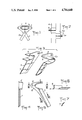
- FIG. 1 is a partial, cross-sectional view of the burner ring body, the toroidal form and the burner ring elements during use of the process according to this invention.
- FIG. 2 is a partial top view of the burner ring as shown in FIG. 1.
- FIG. 3 is an exploded, perspective view of a radial arm burner ring element formed in mirror-image halves.
- FIG. 4 is a rear, elevational view of one of the mirror-image halves shown in FIG. 3.
- FIG. 5 is a side view of the radial arm shown in FIG. 4.
- FIG. 6 is a sectional view taken along line VI--VI in FIG. 5.
- FIG. 7 is a sectional view taken along line VII--VII in FIG. 5.
- FIG. 8 is a side view of a spacer member which may be interposed between the mirror image halves of the radial arm shown in FIG. 3.
- FIG. 9 is a rear view of the spacer member shown in FIG. 8.
- FIG. 10 is a rear view of the radial arm in FIG. 3 showing the mirror image halves assembled together.
- FIG. 11 is a rear view of the mirror-image halves shown in FIG. 3 incorporating the spacer member of FIG. 8 therein.
- FIG. 12 is a rear, elevational view of a fastener clip which may be attached to the burner ring body according to the invention.
- FIG. 13 is a sectional view taken along line XIII--XIII in FIG. 12.
- FIG. 14 is a cross-sectional view taken along line XIV--XIV in FIG. 13.
- FIG. 15 is a side view of a spacer member which may be utilized with the fastening clip shown in FIG. 12.
- FIG. 16 is a rear view of the fastening clip incorporating the spacer member between the mirror-image halves.
- FIG. 17 is a top view of the spacer member shown in FIG. 15.
- FIG. 18 is a side, elevational view of a fuel feed tube element which may be attached to the burner ring body according to the invention.
- FIG. 19 is a front view of one of the mirror-image elements utilized to form the fuel feed tube shown in FIG. 18.
- FIG. 20 is a sectional view taken along line XX--XX in FIG. 18.
- FIG. 21 is a front, elevational view of a burner ring formed according to the invention.
- FIG. 22 is a partial, sectional view taken along line XXII--XXII in FIG. 21.
- FIG. 23 is a partial, cross-sectional view of a first embodiment of an attaching device taken along line XXIII--XXIII in FIG. 21.
- FIG. 24 is a partial, cross-sectional view of an alternative embodiment of the fastening device taken along line XXIII--XXIII in FIG. 21.
- a burner ring structure formed according to this invention is shown in FIG. 21 and may comprise a burner ring body for having a plurality of burner ring elements attached thereto, such as radially inwardly extending arm structure 3, a fastening clip 13, and a fuel feed tube 19.
- the burner ring structure is manufactured by helically winding a refractory ceramic or carbon composite material 2 about the exposed outer surface of a toroidal spindle as shown in FIGS. 1 and 2.
- the toroidal spindle may comprise two separable elements 1 and 1a which are separable along a plane XX 1 which extends substantially perpendicular to the central axis of the toroidal form.
- the toroidal form may have a substantially elliptical cross-section as shown in FIG. 1.
- each of the burner ring elements such as radial arms 3 and 3a are formed of mirror-image halves, as shown in FIG. 3. They are attached to the burner ring body in adjacent pairs, with each one of a pair facing in an opposite direction as shown in FIG. 2.
- the radial arm 3 is attached to one side of the toroidal structure, while radial arm 3a is attached to the opposite side so as to face in an opposite direction.
- the winding of the refractory material is continued until the final thickness of the burner ring body is achieved.
- the entire assembly is then subjected to a carbonization or ceramization heat-treating process until it is fully carbonized or ceramized.
- the burner ring body is cut along the plane X-X 1 extending generally perpendicular to a central axis of the toroid form. After the two elements 1 and 1a of the toroidal form are removed, a pair of burner rings, each having a gutter-shaped, semi-elliptical cross-section are formed.
- Each of the half shells has a half collar 6, a radially extending wall 7 and a flange 8.
- Flange 8 defines an opening 10 to facilitate attachment of the burner ring to the surrounding turbojet engine structure.
- the mirror-image halves 5 and 5a are bonded to each other and to the burner ring body 4 during the previously described winding procedure.
- a spacer 9 (shown in FIGS. 8 and 9) may be interposed between the mirror-image halves 5 and 5a, as shown in FIG. 11.
- the spacer defines an opening 10 to facilitate attachment of the burner ring to the surrounding structure.
- Opening 10 may accommodate pivot pin 11 (see FIGS. 23 and 24) which, in turn, is attached to fastening links 12.
- the opposite end of the links 12 are attached to the turbojet engine structure by known means.
- the burner ring elements may also include fastening clips, formed also of image halves 13 and 13a as shown in FIGS. 12-14. Each of the mirror-image halves may be formed with flange 14 which defines opening 16. Opening 16 performs the same function as opening 10, previously discussed, in attaching the burner ring to a surrounding structure.
- a spacer 15 may be interposed between the mirror-image halves of the fastening clip as shown in FIGS. 15-17.
- spacer 15 defines the attachment opening 16.
- the flanges 14 of the fastening clips are bonded to each other, or to the spacer prior to attaching the assembly to the burner ring during the previously described winding process.
- Another burner ring element may be a fuel feed tube, as shown in FIGS. 18-20, though which pass the feed tubes for a fuel manifold.
- the fuel feed tubes are formed of mirror-image halves 17 and 17a by bonding together mating flanges 18. Each of the halves define a semi-cylindrical cavity 19 to accommodate fuel manifold feed tubes not shown. Once the halves are bonded together, the assembly is attached to the burner ring body 4 by the winding process previously described.
- the fuel feed tube may be formed as element 20, shown in FIG. 21.
Landscapes
- Engineering & Computer Science (AREA)
- Chemical & Material Sciences (AREA)
- Combustion & Propulsion (AREA)
- Mechanical Engineering (AREA)
- General Engineering & Computer Science (AREA)
- Ceramic Engineering (AREA)
- Composite Materials (AREA)
- Gas Burners (AREA)
- Ceramic Products (AREA)
- Pre-Mixing And Non-Premixing Gas Burner (AREA)
Applications Claiming Priority (2)
| Application Number | Priority Date | Filing Date | Title |
|---|---|---|---|
| FR8513794A FR2587455B1 (fr) | 1985-09-18 | 1985-09-18 | Procede de fabrication d'un anneau bruleur en materiau composite et anneau bruleur realise suivant ledit procede |
| FR8513794 | 1985-09-18 |
Publications (1)
| Publication Number | Publication Date |
|---|---|
| US4716640A true US4716640A (en) | 1988-01-05 |
Family
ID=9322998
Family Applications (1)
| Application Number | Title | Priority Date | Filing Date |
|---|---|---|---|
| US06/907,098 Expired - Fee Related US4716640A (en) | 1985-09-18 | 1986-09-15 | Method for manufacturing a burner ring for a turbojet engine |
Country Status (6)
| Country | Link |
|---|---|
| US (1) | US4716640A (ja) |
| EP (1) | EP0215717B1 (ja) |
| JP (1) | JPS6277512A (ja) |
| DE (1) | DE3661439D1 (ja) |
| FR (1) | FR2587455B1 (ja) |
| IL (1) | IL79871A (ja) |
Cited By (3)
| Publication number | Priority date | Publication date | Assignee | Title |
|---|---|---|---|---|
| US5359849A (en) * | 1992-12-16 | 1994-11-01 | Societe Nationale D'etude Et De Construction De Moteurs D'aviation | Afterburner assembly for a gas turbine engine |
| US5367874A (en) * | 1992-12-16 | 1994-11-29 | Societe Nationale D'etude Et De Construction De Moteurs D'aviation (S.N.E.C.M.A.) | Integral composite gas turbine afterburner structure |
| US5444912A (en) * | 1993-10-29 | 1995-08-29 | Folmer; Carroll W. | Method for forming aircraft engine nacelle exhaust mixers and similar products |
Families Citing this family (2)
| Publication number | Priority date | Publication date | Assignee | Title |
|---|---|---|---|---|
| FR2865502B1 (fr) | 2004-01-23 | 2006-03-03 | Snecma Moteurs | Bras monobloc accroche-flammes pour un dispositif de post combustion d'un turboreacteur a double flux |
| FR2981700B1 (fr) * | 2011-10-24 | 2016-08-26 | Snecma Propulsion Solide | Dispositif de fixation d'une piece creuse |
Citations (9)
| Publication number | Priority date | Publication date | Assignee | Title |
|---|---|---|---|---|
| US2780916A (en) * | 1952-08-22 | 1957-02-12 | Continental Aviat & Engineerin | Pilot burner for jet engines |
| US2964907A (en) * | 1957-11-15 | 1960-12-20 | Rolls Royce | Combustion stabilising device for combustion equipment |
| US4148121A (en) * | 1974-06-12 | 1979-04-10 | Messerschmitt-Bolkow-Blohm Gesellschaft Mit Beschrankter Haftung | Method and apparatus for manufacturing rotationally symmetrical constructional parts such as nozzles and combination chambers of rocket engines |
| GB2024403A (en) * | 1978-06-22 | 1980-01-09 | Snecma | Flame-holder |
| US4278485A (en) * | 1978-08-02 | 1981-07-14 | The Boeing Company | Method of forming composite wound structure |
| US4359190A (en) * | 1981-08-18 | 1982-11-16 | The United States Of America As Represented By The Secretary Of The Air Force | Exact involute ply patterns |
| GB2107630A (en) * | 1981-09-11 | 1983-05-05 | Gen Electric | Apparatus for attaching a ceramic member to a metal structure |
| US4440587A (en) * | 1982-08-02 | 1984-04-03 | The United States Of America As Represented By The Secretary Of The Army | Method of making rocket motor case with integral nozzle |
| US4531271A (en) * | 1975-05-22 | 1985-07-30 | Messerschmitt-Bolkow-Blohm Gmbh | Method for manufacturing a rotationally symmetrical construction part |
-
1985
- 1985-09-18 FR FR8513794A patent/FR2587455B1/fr not_active Expired
-
1986
- 1986-08-28 IL IL79871A patent/IL79871A/xx not_active IP Right Cessation
- 1986-09-15 US US06/907,098 patent/US4716640A/en not_active Expired - Fee Related
- 1986-09-16 JP JP61217876A patent/JPS6277512A/ja active Granted
- 1986-09-17 DE DE8686402027T patent/DE3661439D1/de not_active Expired
- 1986-09-17 EP EP86402027A patent/EP0215717B1/fr not_active Expired
Patent Citations (9)
| Publication number | Priority date | Publication date | Assignee | Title |
|---|---|---|---|---|
| US2780916A (en) * | 1952-08-22 | 1957-02-12 | Continental Aviat & Engineerin | Pilot burner for jet engines |
| US2964907A (en) * | 1957-11-15 | 1960-12-20 | Rolls Royce | Combustion stabilising device for combustion equipment |
| US4148121A (en) * | 1974-06-12 | 1979-04-10 | Messerschmitt-Bolkow-Blohm Gesellschaft Mit Beschrankter Haftung | Method and apparatus for manufacturing rotationally symmetrical constructional parts such as nozzles and combination chambers of rocket engines |
| US4531271A (en) * | 1975-05-22 | 1985-07-30 | Messerschmitt-Bolkow-Blohm Gmbh | Method for manufacturing a rotationally symmetrical construction part |
| GB2024403A (en) * | 1978-06-22 | 1980-01-09 | Snecma | Flame-holder |
| US4278485A (en) * | 1978-08-02 | 1981-07-14 | The Boeing Company | Method of forming composite wound structure |
| US4359190A (en) * | 1981-08-18 | 1982-11-16 | The United States Of America As Represented By The Secretary Of The Air Force | Exact involute ply patterns |
| GB2107630A (en) * | 1981-09-11 | 1983-05-05 | Gen Electric | Apparatus for attaching a ceramic member to a metal structure |
| US4440587A (en) * | 1982-08-02 | 1984-04-03 | The United States Of America As Represented By The Secretary Of The Army | Method of making rocket motor case with integral nozzle |
Cited By (3)
| Publication number | Priority date | Publication date | Assignee | Title |
|---|---|---|---|---|
| US5359849A (en) * | 1992-12-16 | 1994-11-01 | Societe Nationale D'etude Et De Construction De Moteurs D'aviation | Afterburner assembly for a gas turbine engine |
| US5367874A (en) * | 1992-12-16 | 1994-11-29 | Societe Nationale D'etude Et De Construction De Moteurs D'aviation (S.N.E.C.M.A.) | Integral composite gas turbine afterburner structure |
| US5444912A (en) * | 1993-10-29 | 1995-08-29 | Folmer; Carroll W. | Method for forming aircraft engine nacelle exhaust mixers and similar products |
Also Published As
| Publication number | Publication date |
|---|---|
| FR2587455B1 (fr) | 1987-10-30 |
| DE3661439D1 (en) | 1989-01-19 |
| FR2587455A1 (fr) | 1987-03-20 |
| JPH0468266B2 (ja) | 1992-10-30 |
| EP0215717B1 (fr) | 1988-12-14 |
| IL79871A (en) | 1993-01-14 |
| IL79871A0 (en) | 1986-11-30 |
| EP0215717A1 (fr) | 1987-03-25 |
| JPS6277512A (ja) | 1987-04-09 |
Similar Documents
| Publication | Publication Date | Title |
|---|---|---|
| US4232843A (en) | Molded nozzle for rocket motor | |
| AU2008295569B2 (en) | Integral composite rocket motor dome/nozzle structure | |
| US7093359B2 (en) | Composite structure formed by CMC-on-insulation process | |
| KR100273054B1 (ko) | 단결정 인상용 도가니 및 그 제조방법 | |
| US3142960A (en) | Multi-material refractory rocket parts and fabrication methods | |
| JPH0116321B2 (ja) | ||
| DE19804232A1 (de) | Brennkammer für Hochleistungstriebwerke und Düsen | |
| EP3708811B1 (en) | Engine exhaust skin connection system | |
| US4716640A (en) | Method for manufacturing a burner ring for a turbojet engine | |
| EP0918976B1 (de) | Verfahren zur Herstellung von Flugkörpern oder Flugkörperkomponenten | |
| CN110370677B (zh) | 一种整流罩的制造方法 | |
| US5032201A (en) | Method for the production of a combustion chamber for solid propellant rocket motor | |
| CN102656357A (zh) | 用于叶栅推力反向器结构的短型框架 | |
| US4907736A (en) | Method of forming articles | |
| GB2201122A (en) | Joining carbon-carbon materials | |
| US4852347A (en) | Advanced composite polar boss | |
| KR101124011B1 (ko) | 수명이 긴 비행기 터보제트용 노즐 플랩 | |
| DE3119712C2 (ja) | ||
| US3103887A (en) | Pre-stressed glass fiber attachment ring | |
| US20250067299A1 (en) | Ceramic matrix composite fastener | |
| US3116547A (en) | Method for coupling a pair of cylindrical members in end-to-end abutment | |
| FR3161004A1 (fr) | Assemblages de tubes composites et procédé de fabrication | |
| US4756248A (en) | Low mass grain support system for solid propellant rocket motors | |
| DE102008020198B4 (de) | Düsenerweiterung für ein Triebwerk und Verfahren zur Herstellung und Kühlung einer Düsenerweiterung | |
| DE102014208923A1 (de) | Verfahren zur Verbindung eines Triebwerk-Gehäuseelements aus Faserverbundmaterial mit einem metallischen Anschlusselement |
Legal Events
| Date | Code | Title | Description |
|---|---|---|---|
| AS | Assignment |
Owner name: SOCIETE NATIONALE ETUDE CONSTRUCTION DE MOTEURS D' Free format text: ASSIGNMENT OF ASSIGNORS INTEREST.;ASSIGNORS:JOURDAIN, GERARD, E. A.;MARLIN, FRANCOIS M. B.;REEL/FRAME:004602/0472 Effective date: 19860908 Owner name: SOCIETE NATIONALE ETUDE CONSTRUCTION DE MOTEURS D' Free format text: ASSIGNMENT OF ASSIGNORS INTEREST;ASSIGNORS:JOURDAIN, GERARD, E. A.;MARLIN, FRANCOIS M. B.;REEL/FRAME:004602/0472 Effective date: 19860908 |
|
| FEPP | Fee payment procedure |
Free format text: PAYOR NUMBER ASSIGNED (ORIGINAL EVENT CODE: ASPN); ENTITY STATUS OF PATENT OWNER: LARGE ENTITY |
|
| CC | Certificate of correction | ||
| FPAY | Fee payment |
Year of fee payment: 4 |
|
| FPAY | Fee payment |
Year of fee payment: 8 |
|
| REMI | Maintenance fee reminder mailed | ||
| LAPS | Lapse for failure to pay maintenance fees | ||
| FP | Lapsed due to failure to pay maintenance fee |
Effective date: 20000105 |
|
| STCH | Information on status: patent discontinuation |
Free format text: PATENT EXPIRED DUE TO NONPAYMENT OF MAINTENANCE FEES UNDER 37 CFR 1.362 |