US4736498A - Tentering chain guide track for roller-supported tenter clamps - Google Patents
Tentering chain guide track for roller-supported tenter clamps Download PDFInfo
- Publication number
- US4736498A US4736498A US07/099,656 US9965687A US4736498A US 4736498 A US4736498 A US 4736498A US 9965687 A US9965687 A US 9965687A US 4736498 A US4736498 A US 4736498A
- Authority
- US
- United States
- Prior art keywords
- guide
- guide rail
- roller
- track
- support roller
- Prior art date
- Legal status (The legal status is an assumption and is not a legal conclusion. Google has not performed a legal analysis and makes no representation as to the accuracy of the status listed.)
- Expired - Fee Related
Links
Images

Classifications
-
- D—TEXTILES; PAPER
- D06—TREATMENT OF TEXTILES OR THE LIKE; LAUNDERING; FLEXIBLE MATERIALS NOT OTHERWISE PROVIDED FOR
- D06C—FINISHING, DRESSING, TENTERING OR STRETCHING TEXTILE FABRICS
- D06C3/00—Stretching, tentering or spreading textile fabrics; Producing elasticity in textile fabrics
- D06C3/02—Stretching, tentering or spreading textile fabrics; Producing elasticity in textile fabrics by endless chain or like apparatus
- D06C3/04—Tentering clips
-
- B—PERFORMING OPERATIONS; TRANSPORTING
- B29—WORKING OF PLASTICS; WORKING OF SUBSTANCES IN A PLASTIC STATE IN GENERAL
- B29C—SHAPING OR JOINING OF PLASTICS; SHAPING OF MATERIAL IN A PLASTIC STATE, NOT OTHERWISE PROVIDED FOR; AFTER-TREATMENT OF THE SHAPED PRODUCTS, e.g. REPAIRING
- B29C55/00—Shaping by stretching, e.g. drawing through a die; Apparatus therefor
- B29C55/02—Shaping by stretching, e.g. drawing through a die; Apparatus therefor of plates or sheets
- B29C55/20—Edge clamps
Definitions
- the invention relates to a tentering chain guide track for tenter clips or clamps supported by rollers in a tentering frame.
- a tentering frame allows the continuous treatment of a material web, especially a film web in a so-called film stretching machine.
- tentering chain guide tracks typically include flexible endless-band-shaped guide rails arranged perpendicularly to the material web.
- the riding or running rollers of the tentering clips which take up the horizontal forces, cooperate with the vertical surface of the guide rail facing the material web as well as with the opposite vertical surface of the guide rail.
- the support rollers which take up the vertical forces are supported by the upper edge of the guide rail.
- a tentering chain guide track having a flexible upright or on-edge clamped guide rail is known, for example from German patent Publication (DE-PS) 1,635,250, disclosing a tentering chain guide track having a vertically clamped guide rail, whereby the two vertical sides of the guide rail serve as running surfaces for the rollers which take up the horizontal tension forces.
- the running rollers bear or press against both sides of the guide rail. Any vertical forces, that is, essentially the weight of the tentering chain, is taken up by special rollers which are supported by a horizontal portion of a chain track carrier.
- Running surfaces for the horizontal rollers are provided both above and below the clamping line on both sides of the guide rail because the guide rail is clamped along its midline, whereby a tipping of the tentering clips is prevented.
- the described vertical support of the tentering clips on the chain track carrier itself is not advantageous in operation and requires special measures at abutting ends of adjacent chain carrier sections, so that the rollers can pass these abutting ends.
- the tenter clips are shaped so that they enclasp the vertically protruding guide rail from above and so that the weight of the tenter clips is supported by a roller contacting the narrow upper edge of the guide rail.
- the tenter clips can tip or tilt about their vertical support point. The resulting tilting moments must be taken up or controlled by the running rollers arranged between the two guide rails, whereby the running rollers alternately contact one or the other of the guide rails which leads to the above mentioned disadvantageous reversal of the running direction of the rollers.
- the above described conventional tenter chain tracks do exhibit a number of advantages. However, it has been shown to be a disadvantage in operation when the tilting moments of the tenter clips are transmitted to and must be taken up by the horizontal rollers. Besides, a symmetric arrangement of the horizontal running rollers is required for this purpose, whereby the number of required rollers cannot be less than a prescribed lower limit. Due to the higher number of rollers, the production costs, as well as the costs for the maintenance of the tentering chain tracks is considerably increased, whereby the economy of such a chain track is reduced. Furthermore, several conventional tentering chains remain plagued by problems at the input of the drive power where the guide rail for the tentering chain must be cut or omitted in the region of the chain drive sprocket for driving the tentering chain.
- the tentering chain guide track of the invention has two flexible endless-band-shaped guide rails.
- a first guide rail is arranged above the material tentering plane on the side of the tentering clips opposite the material web in such a position that the contact surfaces for the running rollers which take up the horizontal forces, lie in the level of said material tentering plane.
- Upper support rollers of the tenter clips contact and run along the upper edge of the first guide rail.
- a second guide rail is arranged in parallel to the first guide rail on the side away from the material web. Lower support rollers for taking up any arising tilting moments of the tenter clips contact the lower edge of the second support rail.
- the two parallel guide rails of the invention may be arranged close together or a spacing falling into a substantial spacing range may be provided between the parallel guide rails.
- Each tenter clip has an upper and a lower arm or shank with which it reaches around the guide rail arrangement respectively from above and below. Support rollers for taking up the vertical forces and the tilting moments, as well as running rollers for taking up the horizontal forces arising during operation as described above, are arranged on these arms.
- Each tenter clip includes at least one, or to greater advantage two, upper support rollers which roll along the upper edge of the first guide rail for carrying the weight of the tenter clips. Generally, a single lower support roller is sufficient as a counter-roller on the lower edge of the other guide rail.
- the running rollers for taking up the horizontal forces are arranged on the lower shank of the tenter clip body in the level of the material tentering plane. Furthermore, at least one running roller is provided on the running surface of the guide rail facing the material web and two running rollers are arranged on the opposite running surface of the guide rail facing away from the material web.
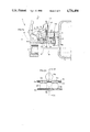
- FIG. 1a is a cross-section through a tentering chain guide track with tenter clips, according to the invention
- FIG. 1b is a top view schematic in the direction of arrow B of FIG. 1a showing the arrangement of the guide rails and rollers of a tenter clip;
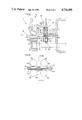
- FIG. 2a is a cross-section similar to FIG. 1a, but of a different embodiment of a tentering chain guide track;
- FIG. 2b is a top view schematic in the direction of the arrow B of FIG. 2a showing the arrangement of the guide rails and rollers of a tenter clip;
- FIG. 3a is a cross-section through a further embodiment of a tentering chain guide track having guide rails placed close together;
- FIG. 3b is a top view schematic in the direction of arrow B in FIG. 3a showing the arrangement of the guide rails and rollers of a tenter clip of FIG. 3a.
- FIGS. 1a and 1b whereby the cross-sectional view of FIG. 1a is a view along section line 1a-1a of the simplified top view of FIG. 1b.
- Flexible or bendable guide rails 4a and 4b are connected by means of clamping or mounting members 3 and support struts 2 in a known manner to a chain track carrying member 1. Since this type of setting the guide rails 4a and 4b to the chain track carrying member 1 as such is known, it is not futher discussed. However, according to the invention two parallel extending guide rails 4a and 4b are used instead of a single guide rail typical in the prior art.
- a spacer block 2' arranged between the two rails 4a and 4b maintains the spacing between these two rails.
- Each guide rail 4a and 4b typically comprises a packet of flexible spring steel bands arranged in an upright or on-edge manner.
- the guide rail 4a is arranged closer to the material web W and comprises vertical side surfaces 41 and 42 facing toward and away from the material web W, respectively.
- the lower portions of the surfaces 41 and 42 protruding downwardly out of the clamping member 3 or spacer block 2' serve as running surfaces for the horizontal running rollers 5a and 5b, respectively.
- the upper edge 45 of the guide rail 4a serves as a running surface for upper support rollers 6a which carry the weight of the tenter clips. In this embodiment, the downwardly facing edge of the guide rail 4a is not utilized.
- the guide rail 4b which lies closer to the chain track carrying member 1 and further from the material web W is similarly constructed and arranged.
- the rail 4b comprises vertical side surfaces 43 and 44 which may similarly be used as running surfaces for horizontal running rollers, but which are not used as such in this embodiment.
- the lower edge 46 of the guide rail 4b serves as a running surface for lower support roller 6b.
- the upper edge of the guide rail 4b is not utilized here. Therefore, the guide rail 4b may be narrower than the first guide rail 4a and only needs to protrude downwardly below the strut 2 far enough so that a support roller 6b comes into contact with the lower surface 46 for preventing, in cooperation with an upper support roller 6a, a tilting or tipping of the tenter clip.
- FIG. 1a further shows the arrangement of a tenter clip K with a tentering arm for clamping a material web W against the bottom Kl of the clip K.
- the material tentering plane E is shown by a dash-dotted line coinciding with the web W.
- the tenter clip K of FIG. 1a is sectioned through its middle.
- the body of the tenter clip K reaches around or enclasps the guide rail arrangement in a C-shape, whereby upper arms or struts 10 of the C-shaped tenter clip body carry at least one or more, advantageously two, upper support rollers 6a.
- FIG. 1b shows that the upper edge 45 of the inner guide rail 4a supports two upper support rollers 6a and 6a' per tenter clip, whereas the lower edge 46 of the outer guide rail 4b only supports one support roller 6b. In some cases, it may be sufficient to provide only a single upper support roller 6a per tenter clip.
- the lower arm 11 of the C-shaped tenter clip body K carries running or guide rollers 5a and 5b. These running or guide rollers 5a and 5b are arranged in the level of the material tentering plane E, whereby the running roller 5b contacts the outer running surface 42 of the inner guide rail 4a for taking up the horizontal tension forces arising during operation. On the other hand, when an oppositely directed compressive force arises, the inner running roller 5a contacts the inner running surface 41 of the inner guide rail 4a.
- FIG. 1b shows the advantageous arrangement of running rollers in two pairs per tenter clip, namely a first pair 5a, 5b, and a second pair 5a', 5b'. Each roller of a pair is arranged on opposite sides of the inner guide rail 4a. However, it is also possible to provide a different distribution or arrangement of the running or guide rollers.
- the guide rails 4a and 4b which extend in parallel to each other, are held at a defined spacing from each other by a spacer block 2' so that the outer running roller 5b can be guided between the two guide rails 4a and 4b.
- the guide rail 4a closer to the clip K protrudes downwardly from the spacer block 2' only far enough so that the running roller pair 5a, 5b can contact a sufficient running surface on the side surfaces 41 and 42 of the guide rail 4a.
- the guide rail 4b protrudes downwardly from the strut 2 far enough so that the lower support roller 6b lies below the plane E of the running rollers 5a and 5b.
- FIG. 1a a chain roller 7 is shown intermeshing with a drive sprocket 8.
- the components of the tentering chain guide track are arranged so that the drive sprocket 8 can freely rotate below the running rollers 5a, 5b and the support rollers 6a, 6a'. The cutting or omission of the guide rail at the turning points or drive points is thereby avoided.
- the arrangement according to the invention achieves a very uniform distribution of the horizontal tensile forces on the rollers and prevents the tipping or tilting of the tenter clips in a simple manner by means of the displaced arrangement of the two guide rails and the support rollers.
- only a few rollers are required, namely three or four running rollers and two or three support rollers.
- FIGS. 2a and 2b has essentially the same structure as the embodiment of FIGS. 1a and 1b and will therefore be described only to the extent of the differences.
- One difference is seen in that the spacing between the two parallel guide rails 4a and 4b is smaller in FIG. 2a than in FIG. 1a.
- the embodiment of FIG. 2a comprises a shorter spacer block 2'.
- the outer guide rail 4b is arranged closer to the inner guide rail 4a and only protrudes a small distance below the strut 2 so that the lower edge 46 is exposed just enough to act as a contact or running surface for the lower support roller 6b.
- the lower edge 46 of the guide rail 4b no longer lies lower than the running rollers 5a, 5b as is shown in FIG.
- the edge 46 is located higher than the rollers 5a and 5b.
- the lower support roller 6b is also moved to a higher position as can be seen in FIGS. 2a and 2b so that it partially protrudes upwardly between the running rollers 5b and 5b'.
- a further difference of the embodiment of FIG. 2b is the fact that only three horizontal running rollers are required as shown.
- the horizontal tensile forces arising during operation are taken up by the two running rollers 5b and 5b' which contact the outer running surface 42 of the inner guide rail 4a.
- a single running roller 5a is arranged for taking up the oppositely directed compressive forces, whereby this roller 5a contacts the surface 41 of the guide rail 4a. If the spacing between the two running rollers 5b and 5b' is sufficiently large so that the lower support roller 6b may be arranged between the running rollers 5b and 5b', then the spacing maintained by the spacer block 2' between the two parallel guide rails 4a and 4b may be decreased still further.
- FIGS. 3a and 3b show an embodiment in which the spacing between the two parallel flexible guide rails 4a and 4b has been further reduced substantially to zero.
- the two guide rails are now practically adjacent without any interspacing, except for at most, a thin spacer shim 9.
- two similar guide rails 4a and 4b are so arranged that one side surface of each guide rail serves as a running surface for the running rollers 5a or 5b.
- the side facing the material web W for the side surface 41 of the inner guide rail 4a cooperates with the inner running roller 5a, whereas the side facing away from the material web W or the outer side surface 44 of the guide rail 4b cooperates with the outer running rollers 5b.
- the upper support roller 6a rolls on the upper edge 45 of the inner guide rail 4a and the lower support roller 6b rolls on the lower edge 46 of the guide rail 4b as in the other embodiments.
- the two guide rails 4a and 4b are slightly displaced vertically with respect to each other so that the upper edge 45 of the guide rail 4a protrudes above the guide rail 4b, whereas the lower edge 46 of the guide rail 4b protrudes below the guide rail 45.
- defined separate contact surfaces 45 or 46 are provided for the support rollers 6a or 6b, respectively.
- the level difference between the two guide rails may be less than 1 mm. This arrangement ensures an advantageous rolling operation and furthermore, the contact surface edges are not subject to curling roll-over damage caused by the continuous movement of the support rollers.
- the three vertically arranged support rollers 6a, 6b, and 6a' also take up any other vertically directed moments and forces which may act on the tenter clips.
- the forces acting in a horizontal direction on the tenter clips are transmitted to the flexible guide rails through a set of running rollers comprising two roller pairs 5a, 5a' and 5b, 5b'.
- the number and arrangement of the rollers may also be varied in this exmaple embodiment as in the others.
- a further advantage of all the example embodiments shown in the Figures is that the horizontal distance between the gripping edge of the tenter clips and the center line of the chain links can be made very small, whereby a smooth running operation and other good characteristics of the tentering chain is achievable e.g. a uniform stretching of the film without wrinkles.
Landscapes
- Engineering & Computer Science (AREA)
- Mechanical Engineering (AREA)
- Textile Engineering (AREA)
- Advancing Webs (AREA)
- Shaping By String And By Release Of Stress In Plastics And The Like (AREA)
- Treatment Of Fiber Materials (AREA)
Applications Claiming Priority (2)
| Application Number | Priority Date | Filing Date | Title |
|---|---|---|---|
| DE3529514A DE3529514C1 (de) | 1985-08-17 | 1985-08-17 | Kluppenkettenbahn fuer Spannkluppen mit Rollenlagerung in Spannrahmen zur kontinuierlichen Behandlung eine Warenbahn |
| DE3529514 | 1985-08-17 |
Related Parent Applications (1)
| Application Number | Title | Priority Date | Filing Date |
|---|---|---|---|
| US06893480 Continuation | 1986-08-05 |
Publications (1)
| Publication Number | Publication Date |
|---|---|
| US4736498A true US4736498A (en) | 1988-04-12 |
Family
ID=6278758
Family Applications (1)
| Application Number | Title | Priority Date | Filing Date |
|---|---|---|---|
| US07/099,656 Expired - Fee Related US4736498A (en) | 1985-08-17 | 1987-09-21 | Tentering chain guide track for roller-supported tenter clamps |
Country Status (6)
| Country | Link |
|---|---|
| US (1) | US4736498A (it) |
| JP (1) | JPS6241150A (it) |
| DE (1) | DE3529514C1 (it) |
| FR (1) | FR2586263B1 (it) |
| GB (1) | GB2179071B (it) |
| IT (2) | IT1195134B (it) |
Cited By (7)
| Publication number | Priority date | Publication date | Assignee | Title |
|---|---|---|---|---|
| US5613284A (en) * | 1996-04-30 | 1997-03-25 | Marshall & Williams Company | Tenter assembly and method |
| US5797172A (en) * | 1996-04-30 | 1998-08-25 | Marshall And Williams Company | Tenter frame and method |
| US5896631A (en) * | 1997-04-21 | 1999-04-27 | Lindauer Dornier Gesellschaft Mbh | Spring steel tape tentering clamp guide rail with such tape |
| US5924180A (en) * | 1995-04-24 | 1999-07-20 | Bruckner Maschinenbau Gmbh | Transport device and associated guiding rail |
| US5933930A (en) * | 1997-03-03 | 1999-08-10 | Lindauer Dornier Gesellschaft Mbh | Guide rail for tenter clamps in tentering machines, especially film stretching machines |
| US11167468B2 (en) * | 2017-08-01 | 2021-11-09 | Brückner Maschinenbau GmbH & Co. KG | Stretching system |
| US20230016645A1 (en) * | 2021-07-16 | 2023-01-19 | The Japan Steel Works, Ltd. | Link device and stretching machine |
Families Citing this family (2)
| Publication number | Priority date | Publication date | Assignee | Title |
|---|---|---|---|---|
| DE102015109601A1 (de) * | 2015-03-27 | 2016-09-29 | Schlatter Deutschland Gmbh & Co. Kg | Gewebe-Breithalter einer Ausrüstungsmaschine |
| DE202016101424U1 (de) | 2015-03-27 | 2016-04-20 | Schlatter Deutschland Gmbh & Co. Kg | Gewebe-Breithalter einer Ausrüstungsmaschine |
Citations (9)
| Publication number | Priority date | Publication date | Assignee | Title |
|---|---|---|---|---|
| US3391421A (en) * | 1966-06-06 | 1968-07-09 | Eastman Kodak Co | Apparatus for biaxial stretching of a polymeric sheet |
| US3469291A (en) * | 1964-11-28 | 1969-09-30 | Lindaure Dornier Gmbh | Chain track assembly for tenter clips |
| DE1925284A1 (de) * | 1969-05-17 | 1970-11-19 | Dornier Gmbh Lindauer | Kluppenkette fuer Spannkluppen in Spannrahmen |
| DE1635250A1 (de) * | 1966-08-25 | 1971-06-24 | Dornier Gmbh Lindauer | Kluppenkette fuer Spannkluppen mit Rollenlagerung |
| JPS5131275A (en) * | 1974-09-10 | 1976-03-17 | Osaka Meetaa Seizo Kk | Takishiimeetaa no dendokishikitokeikiko |
| FR2317076A2 (fr) * | 1975-07-07 | 1977-02-04 | Cellophane Sa | Dispositif ameliore d'etirage des films de matiere plastique |
| DE2558765B1 (de) * | 1975-12-24 | 1977-03-24 | Dornier Gmbh Lindauer | Spannrahmen zum kontinuierlichen Behandeln eines bahnfoermigen Behandlungsgutes |
| US4176429A (en) * | 1977-03-22 | 1979-12-04 | Lindauer Dornier Gesellschaft Mbh | Apparatus for cleaning clamping surfaces |
| JPS59135127A (ja) * | 1983-01-21 | 1984-08-03 | Mitsubishi Heavy Ind Ltd | テンタ−クリツプの走行装置 |
Family Cites Families (4)
| Publication number | Priority date | Publication date | Assignee | Title |
|---|---|---|---|---|
| US3457608A (en) * | 1965-09-15 | 1969-07-29 | Dornier Gmbh Lindauer | Chain track assembly for tenter clips |
| US3748704A (en) * | 1972-01-04 | 1973-07-31 | Kampf Maschf Erwin | Clamp for biaxial stretching machines |
| DE2849628C3 (de) * | 1978-11-16 | 1981-08-06 | Lindauer Dornier-Gesellschaft Mbh, 8990 Lindau | Spannkluppe |
| FR2486113A1 (fr) * | 1980-07-01 | 1982-01-08 | Dornier Gmbh Lindauer | Dispositif de guidage de la chaine a pinces d'une rame |
-
1985
- 1985-08-17 DE DE3529514A patent/DE3529514C1/de not_active Expired
-
1986
- 1986-05-28 JP JP61121413A patent/JPS6241150A/ja active Pending
- 1986-07-04 FR FR868609781A patent/FR2586263B1/fr not_active Expired - Fee Related
- 1986-07-21 GB GB8617738A patent/GB2179071B/en not_active Expired
- 1986-08-12 IT IT67655/86A patent/IT1195134B/it active
- 1986-08-12 IT IT8653754U patent/IT8653754V0/it unknown
-
1987
- 1987-09-21 US US07/099,656 patent/US4736498A/en not_active Expired - Fee Related
Patent Citations (10)
| Publication number | Priority date | Publication date | Assignee | Title |
|---|---|---|---|---|
| US3469291A (en) * | 1964-11-28 | 1969-09-30 | Lindaure Dornier Gmbh | Chain track assembly for tenter clips |
| US3391421A (en) * | 1966-06-06 | 1968-07-09 | Eastman Kodak Co | Apparatus for biaxial stretching of a polymeric sheet |
| DE1635250A1 (de) * | 1966-08-25 | 1971-06-24 | Dornier Gmbh Lindauer | Kluppenkette fuer Spannkluppen mit Rollenlagerung |
| DE1925284A1 (de) * | 1969-05-17 | 1970-11-19 | Dornier Gmbh Lindauer | Kluppenkette fuer Spannkluppen in Spannrahmen |
| US3638289A (en) * | 1969-05-17 | 1972-02-01 | Dornier Gmbh Lindauer | Tenter frame assembly |
| JPS5131275A (en) * | 1974-09-10 | 1976-03-17 | Osaka Meetaa Seizo Kk | Takishiimeetaa no dendokishikitokeikiko |
| FR2317076A2 (fr) * | 1975-07-07 | 1977-02-04 | Cellophane Sa | Dispositif ameliore d'etirage des films de matiere plastique |
| DE2558765B1 (de) * | 1975-12-24 | 1977-03-24 | Dornier Gmbh Lindauer | Spannrahmen zum kontinuierlichen Behandeln eines bahnfoermigen Behandlungsgutes |
| US4176429A (en) * | 1977-03-22 | 1979-12-04 | Lindauer Dornier Gesellschaft Mbh | Apparatus for cleaning clamping surfaces |
| JPS59135127A (ja) * | 1983-01-21 | 1984-08-03 | Mitsubishi Heavy Ind Ltd | テンタ−クリツプの走行装置 |
Cited By (8)
| Publication number | Priority date | Publication date | Assignee | Title |
|---|---|---|---|---|
| US5924180A (en) * | 1995-04-24 | 1999-07-20 | Bruckner Maschinenbau Gmbh | Transport device and associated guiding rail |
| US5613284A (en) * | 1996-04-30 | 1997-03-25 | Marshall & Williams Company | Tenter assembly and method |
| US5797172A (en) * | 1996-04-30 | 1998-08-25 | Marshall And Williams Company | Tenter frame and method |
| US5933930A (en) * | 1997-03-03 | 1999-08-10 | Lindauer Dornier Gesellschaft Mbh | Guide rail for tenter clamps in tentering machines, especially film stretching machines |
| US5896631A (en) * | 1997-04-21 | 1999-04-27 | Lindauer Dornier Gesellschaft Mbh | Spring steel tape tentering clamp guide rail with such tape |
| US11167468B2 (en) * | 2017-08-01 | 2021-11-09 | Brückner Maschinenbau GmbH & Co. KG | Stretching system |
| US20230016645A1 (en) * | 2021-07-16 | 2023-01-19 | The Japan Steel Works, Ltd. | Link device and stretching machine |
| US12214542B2 (en) * | 2021-07-16 | 2025-02-04 | The Japan Steel Works, Ltd. | Link device and stretching machine |
Also Published As
| Publication number | Publication date |
|---|---|
| GB8617738D0 (en) | 1986-08-28 |
| IT1195134B (it) | 1988-10-12 |
| IT8667655A0 (it) | 1986-08-12 |
| FR2586263B1 (fr) | 1990-07-13 |
| FR2586263A1 (fr) | 1987-02-20 |
| GB2179071B (en) | 1989-08-02 |
| JPS6241150A (ja) | 1987-02-23 |
| DE3529514C1 (de) | 1987-01-02 |
| GB2179071A (en) | 1987-02-25 |
| IT8653754V0 (it) | 1986-08-12 |
Similar Documents
| Publication | Publication Date | Title |
|---|---|---|
| US4736498A (en) | Tentering chain guide track for roller-supported tenter clamps | |
| US5081750A (en) | Gripper carriage and transport assembly for a stretching frame | |
| US5613284A (en) | Tenter assembly and method | |
| EP0591206A4 (en) | IMPROVEMENTS TO LOWER CONVEYOR DRIVE ROLLERS. | |
| SE8303078L (sv) | Anordning for lengsgaende styrning av en endlos bana | |
| KR920700887A (ko) | 시트의 폭확장 및 고정장치 | |
| US5797172A (en) | Tenter frame and method | |
| US4674159A (en) | Stenter frame clip chain assembly | |
| ATE156436T1 (de) | Diagonal bewegliche gliederbrücke als teil eines übergangs zwischen zwei fahrzeugen | |
| ATE81487T1 (de) | Senkrechtfoerderer. | |
| GB2032975A (en) | Clip Chain Track | |
| US4435884A (en) | Clip-chain track for tenter clips | |
| US5390398A (en) | Foil stretching machine for shrinking foils | |
| KR930004174A (ko) | 복합 곡선을 이루고 있는 스플라이서판을 구비한 스플라이서 기구 | |
| US4440294A (en) | Conveyor | |
| US5933930A (en) | Guide rail for tenter clamps in tentering machines, especially film stretching machines | |
| IT1271653B (it) | Controllore di posizione di rullo per pressa a nastro continuo | |
| US5896631A (en) | Spring steel tape tentering clamp guide rail with such tape | |
| JPS6011645B2 (ja) | 垂直持上機 | |
| GB2176510A (en) | Clip chain track of a stenter frame | |
| SU1169903A1 (ru) | Устройство дл центрировани ленты конвейера | |
| SU562410A1 (ru) | Транспортное устройство | |
| EP0573119B1 (en) | Roller conveyor | |
| GB2264918A (en) | Conveying apparatus. | |
| SU1687547A1 (ru) | Устройство дл намотки рулонных материалов |
Legal Events
| Date | Code | Title | Description |
|---|---|---|---|
| AS | Assignment |
Owner name: LINDAUER DORNIER GESELLSCHAFT MBH, RICKENBACHERSTR Free format text: ASSIGNMENT OF ASSIGNORS INTEREST.;ASSIGNORS:LANGER, RUDOLF;KOSZIECH, KARL HEINZ;REEL/FRAME:004789/0347 Effective date: 19860729 Owner name: LINDAUER DORNIER GESELLSCHAFT MBH, RICKENBACHERSTR Free format text: ASSIGNMENT OF ASSIGNORS INTEREST;ASSIGNORS:LANGER, RUDOLF;KOSZIECH, KARL HEINZ;REEL/FRAME:004789/0347 Effective date: 19860729 |
|
| CC | Certificate of correction | ||
| REMI | Maintenance fee reminder mailed | ||
| LAPS | Lapse for failure to pay maintenance fees | ||
| FP | Lapsed due to failure to pay maintenance fee |
Effective date: 19920412 |
|
| STCH | Information on status: patent discontinuation |
Free format text: PATENT EXPIRED DUE TO NONPAYMENT OF MAINTENANCE FEES UNDER 37 CFR 1.362 |