US4750880A - Compliant print head loading mechanism for thermal printers - Google Patents
Compliant print head loading mechanism for thermal printers Download PDFInfo
- Publication number
- US4750880A US4750880A US07/118,665 US11866587A US4750880A US 4750880 A US4750880 A US 4750880A US 11866587 A US11866587 A US 11866587A US 4750880 A US4750880 A US 4750880A
- Authority
- US
- United States
- Prior art keywords
- lower bracket
- head
- pivot shaft
- slot
- print head
- Prior art date
- Legal status (The legal status is an assumption and is not a legal conclusion. Google has not performed a legal analysis and makes no representation as to the accuracy of the status listed.)
- Expired - Lifetime
Links
Images



Classifications
-
- B—PERFORMING OPERATIONS; TRANSPORTING
- B41—PRINTING; LINING MACHINES; TYPEWRITERS; STAMPS
- B41J—TYPEWRITERS; SELECTIVE PRINTING MECHANISMS, i.e. MECHANISMS PRINTING OTHERWISE THAN FROM A FORME; CORRECTION OF TYPOGRAPHICAL ERRORS
- B41J25/00—Actions or mechanisms not otherwise provided for
- B41J25/304—Bodily-movable mechanisms for print heads or carriages movable towards or from paper surface
- B41J25/316—Bodily-movable mechanisms for print heads or carriages movable towards or from paper surface with tilting motion mechanisms relative to paper surface
Definitions
- the present invention relates to thermal printers and more specifically to a mechanism for controlling the position of the print head during a full printing cycle.
- a web-type carrier containing a repeating series of spaced frames of different colored heat transferable dyes is spooled on a supply spool.
- the carrier is paid out from the supply spool and rewound on a take-up spool.
- the carrier moves through a nip formed between a thermal print head and a dye-absorbing receiver.
- the receiver in turn is supported by a platen in the form of a drum.
- the print head engages the dye-carrier and presses it against the receiver.
- the receiver may, for example, be coated paper and the print head is formed of, for example, a plurality of heating elements. When a particular heating element is energized, it is heated.
- the web-type carrier often includes a repeating series of spaced yellow, magenta and cyan dyes frames.
- the carrier is typically formed of a very thin, flexible dye carrying member having a thickness that can be on the order of 1/4 mil.
- the head must be locked off the drum to allow a cut-sheet dye-receiver to be wrapped onto the drum and advanced under the head. This pre-printing process requires that the drum turn without the head or dye-carrier in contact with drum.
- the first dye patch typically yellow, is advanced to a position under the print head. The print head is lowered to apply pressure on the carrier-donor sandwich as the platen turns.
- the media sandwich slides under the print head and the heating elements are selectively energized to form a row of yellow image pixels under the print head.
- the drum turns to generate successive rows of the yellow portion of the final image.
- the head is lifted to reposition the dye-receiver for the next color frame.
- the dye-carrier is controlled during the repositioning so that the next dry frame, for example magenta, is positioned under the print head.
- the head is lowered to reestablish contact with the media, and the next color plane is deposited on the receiver.
- the process of head lift, receiver repositioning and preparation for the next dye patch is repeated for the final dye-frame, in this case the cyan frame.
- the three dyes are blended during the deposition process to generate a full-color image. After the three color portions of the image have been deposited, the printing process is completed. The head must be lifted again to allow the platen to turn and eject the completed image. The head must continue to be held up to reload the platen for the next cut sheet dye-receiver.
- the process of applying the head to the drum must be done in a manner that allows the head to be positioned accuratley, repeatedly, and with uniform pressure across the platen to provide a high-quality print.
- the thermal head's linear array of heating elements should be positioned tangent to the drum and centered radially over the drum surface. In addition, the heating element array should be pressed against the drum surface with uniform force. Because manufactured parts vary from perfect dimension, the mechanism should be assigned to minimize the effect of these dimensional errors on print quality.
- the accuracy of the head position is ensured by minimizing the number of components between the drum and the head and in the shape and nature of each part's features. If this accuracy cannot be built into the head support mechanism, adjustments must be built in. Such adjustments add to the complexity and expense of the assembly.
- the repeatability of the mechanism is guaranteed if the head returns to the same position after a lift-and-lower cycle. If the head doesn't return to the same position for each of the dye layers, the resolution of the image will be degraded. It is preferable that the head must not only lift off of the drum during the printing, but that the head should be moved significantly out of the way for service procedures.
- a compliant head loading mechanism for a thermal printer which in a loaded condition compliantly loads a thermal head against a dye-carrier and a receiver mounted on a platen such as a drum to form a nip, comprising:
- a lower bracket fixed securely to said thermal head and having two arms each having a hole that receives said pivot shaft to pivotably mount said lower bracket, one of said holes being a tight tolerance hole that only permits rotational motion of said lower bracket and the other hole being in the form of a slot with major and minor axes constructed to permit both rotational and translation motion of said lower bracket, said slot being configured such that a line extending from the nip and the center axis of said pivot shaft is perpendicular to said major slot axis;
- said cam member being configured and located to move said print head into and out of a loaded condition, wherein said thermal head is compliantly loaded by said spring to form said nip, whereby the loading force is uniformly distributed across the nip and no twisting moment is induced in said lower bracket.
- This invention permits highly accurate positioning of print heads. This is due to the print head position on the platen (drum surface) being done through the lower bracket. Elimination of intermediate parts reduces tolerance error stack-up, thus reducing positioning error.
- the print head alignment with the drum is controlled by dimensional control of the lower bracket.
- An advantage of this system over other mechanical head lift systems is that the print head readily can be lifted or lowered at any point in time. This feature can be useful for initialization functions and error recovery.
- the slot in one arm of the lower bracket permits the print head to be uniformly loaded against the drum surface. This eliminates head contact pressure adjustments.
- An important feature of the slot is the tilt used to compensate for twist induced by the drag force of the drum. If the force of the drag is sufficient it can introduce a twisting moment in the lower bracket. Instead of a uniform loading, this twist causes the load induced by the load spring to be biased. This variation in pressure across the nip causes a density variation across the print in the receiver. This undesirable effect is eliminated when the slot is oriented so that is perpendicular to a line drawn between the nip and the centerline of the pivot shaft. Based on this principle, the tilt of the slot can be readily determined.
- the two brackets share a common pivot, they can be swung off the drum as a single unit to allow greater accessability to the printing area. The two parts return to the printing position virtually undisturbed. This ensures reliable positioning of the print head.
- FIG. 1 is a schematic of a thermal printer apparatus which can be employed to make colored image in a receiver
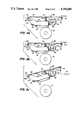
- FIG. 2 is a bottom view of a compliant head loading mechanism in accordance with the present invention.
- FIGS. 3a-c are views taken along the lines 3--3 of FIG. 2, showing the head loading mechanism in a "loaded" print position, a carrier advance position, and a mechanism servicing position, respectively;
- FIGS. 4a and 4b respectively show in schematic different slot alignment arrangements in accordance with the invention.
- FIG. 1 shows a schematic of a thermal printer apparatus 10.
- the thermal printer apparatus 10 employs a receiving member in the form of a cut receiver sheet 12, which is secured by a clamp (not shown) to a rotatably drum 16.
- the drum 16 is driven by a drive mechanism 15.
- Drive mechanism 15 continuously rotates drum 16 and thus the successive portions of the receiver sheet 12 past a print head 18.
- print head 18 has been shown as a block and the head loading mechanism in accordance with the present invention is illustrated in the remaining drawings.
- Thermal print head 18 is conventional and includes a plurality of heating elements (not shown).
- Compliant head loading mechanism presses the print head against a dye-carrier 14 and the receiver sheet mounted on the drum 16 to form a printing nip.
- the dye-carrier member 14 is mounted in a cartridge and is driven along path from a cartridge supply spool 21 into a take-up spool 22 by a drive mechanism 23.
- the mechanism 23 drives a gear (not shown) on the spool 22 which causes the dye-carrier to advance.
- the drive mechanism 15 continuously advances the receiver 12 and the carrier 14 (via frictional engagement with the receiver at the print head) relative to the line of heating elements of the print head as the heating elements are selectively energized by print head control circuitry 24.
- Microcomputer 17 controls the operation of the mechanism 15 and 23 as well as the print head control circuitry 24.
- the dye-carrier 14 includes a repeating series of thermally transferable dyes. Each series typically may includes frames of yellow, magenta and cyan dye frames. A series of these three dye frames is used to print a full colored image on the receiver sheet 12.
- the term "dye” refers to a colored material which transfer from the dye-carrier 14 to the receiver sheet 12 in response to energy applied by the individual heating elements of the print head 18.
- the thermal head 18 is lifted from its loaded position shown in FIG. 3a to an off-drum or open position shown in FIG. 3b.
- the drive mechanism 15 then continuous to rotate the drum 16 until the receiver 12 has been stripped off the drum 16. Holding the print head off of the drum 16 during receiver sheet loading and unloading prevents head drag on the drum 16 and allows the carrier 14 to remain in position without being removed from either spool 21 or 22.
- the head loading mechanism includes two brackets, upper bracket 29 and lower bracket 30.
- the print head 18 is fixedly secured to a central portion 32 of the lower bracket 30 by means not shown.
- the bracket 30 includes two parallel arms 36 and 38 which are formed perpendicular the central portion 32.
- a pivot shaft 39 passes through holes 40a and 40b respectively formed in each of the pivot arms 36 and 38.
- the hole 40a is circular in configuration and is formed to provide a tight tolerance fit relative to the fixed pivot shaft 39 so as to permit only rotational motion of the bracket 30.
- the second hole 40b is a slot and is arranged so that the lower bracket 30 can both translate and rotate in such slot.
- the slot 40b has major and minor axes.
- the slot 40b is aligned so as to prevent the drag forces of the rotating drum 16 on the media from inducing twist in the lower bracket 30.
- the slot tilt permits the lower bracket 30 to comply to the drum surface at the nip.
- the slot 40b is aligned so that the major axis of the slot is perpendicular to a line running from the printing nip to the center axis of the pivot shaft 39. This prevents the twisting moment. Uniform loading force is thereby uniformly distributed across the nip.
- FIGS. 4a and 4b show in schematic form different constructions of the lower bracket.
- the slot 40b is arranged so that its major axis is perpendicular to a line drawn between the center axis of the shaft and the printing nip.
- the lower bracket 30 includes a free end portion 44 which is engageable by a cam 46.
- the cam 46 is fixedly secure to a rotatable shaft 48 which is mounted in arms 50 and 52 of the upper bracket 29.
- a compression spring 56 is fixedly secure to the central portion 54 of the upper bracket 29 and the central portion 32 of the lower bracket 30. As shown in FIG. 3a in the loaded position, the spring 56 causes the lower bracket 30 to move such that the head is driven into engagement with the drum 16.
- the receiver sheet 12 and the carrier 14 are not shown for simplicity of illustration.
- the lift cam 46 has its profile shaped such that is is actually spaced from the free-end portion 44. After a particular color frame has been formed in the receiver sheet, lift cam 46 is rotated to the position shown in FIGS. 3b, engages the end portion 44 and drives the lower bracket 30 upwardly so that the print head 18 is spaced from the drum 16.
- a latching mechanism 58 securely latches the upper bracket 29 in the position shown in FIG. 3a and 3b, during the operation of the thermal printing apparatus when a full colored image is being formed.
- the latch 58 When the apparatus is to be serviced, the latch 58 is manually removed from disengagement with the upper bracket 29 and both the upper and lower brackets can be pivoted to the position shown in FIG. 3c. In this position, the compression spring 56 moves the lower bracket downwardly to a position so that its free end portion 44 engages the cam 46. This arrangement allows the head loading mechanism to be swung away from the drum while still holding the two brackets together.
- the arms of the upper bracket each includes holes to permit this bracket to be pivotably mounted on the fixed pivot shaft. There is no need for these holes to have a tight tolerance. Also, although not shown, it will be understood that a small DC motor can be used to drive the lift cam 46. This motor may also be controlled by the microcomputer 17 shown in FIG. 2. Further, web sensing apparatus can also be mounted on the upper bracket 29.
Landscapes
- Common Mechanisms (AREA)
- Electronic Switches (AREA)
Priority Applications (5)
| Application Number | Priority Date | Filing Date | Title |
|---|---|---|---|
| US07/118,665 US4750880A (en) | 1987-11-09 | 1987-11-09 | Compliant print head loading mechanism for thermal printers |
| EP88910289A EP0346412B1 (de) | 1987-11-09 | 1988-10-31 | Belastungsmechanismus für einen nachgiebigen druckkopf in thermodruckern |
| JP63509392A JP2914382B2 (ja) | 1987-11-09 | 1988-10-31 | サーマルプリンタのための追従性印刷ヘッドの負荷装置 |
| DE8888910289T DE3873326T2 (de) | 1987-11-09 | 1988-10-31 | Belastungsmechanismus fuer einen nachgiebigen druckkopf in thermodruckern. |
| PCT/US1988/003853 WO1989004256A1 (en) | 1987-11-09 | 1988-10-31 | Compliant print head loading mechanism for thermal printers |
Applications Claiming Priority (1)
| Application Number | Priority Date | Filing Date | Title |
|---|---|---|---|
| US07/118,665 US4750880A (en) | 1987-11-09 | 1987-11-09 | Compliant print head loading mechanism for thermal printers |
Publications (1)
| Publication Number | Publication Date |
|---|---|
| US4750880A true US4750880A (en) | 1988-06-14 |
Family
ID=22380007
Family Applications (1)
| Application Number | Title | Priority Date | Filing Date |
|---|---|---|---|
| US07/118,665 Expired - Lifetime US4750880A (en) | 1987-11-09 | 1987-11-09 | Compliant print head loading mechanism for thermal printers |
Country Status (5)
| Country | Link |
|---|---|
| US (1) | US4750880A (de) |
| EP (1) | EP0346412B1 (de) |
| JP (1) | JP2914382B2 (de) |
| DE (1) | DE3873326T2 (de) |
| WO (1) | WO1989004256A1 (de) |
Cited By (24)
| Publication number | Priority date | Publication date | Assignee | Title |
|---|---|---|---|---|
| US4815870A (en) * | 1987-10-22 | 1989-03-28 | Eastman Kodak Company | Receiver clamping arrangement for thermal printers |
| US4957379A (en) * | 1989-01-11 | 1990-09-18 | Monarch Marking Systems, Inc. | Printing apparatus |
| EP0361826A3 (en) * | 1988-09-26 | 1990-12-27 | Shinko Denki Kabushiki Kaisha | Thermal head supporting means for a thermal printing system |
| US5023628A (en) * | 1989-03-21 | 1991-06-11 | Esselte Meto International Produktions Gmbh | Thermal head mounting/positioning assembly |
| DE9103111U1 (de) * | 1991-03-14 | 1991-07-18 | Höttler, Wolfgang, Dr., 4630 Bochum | Kartenverarbeitungseinheit zum magnetischen Codieren und Decodieren von Datenträgern |
| US5069557A (en) * | 1987-11-19 | 1991-12-03 | Brother Kogyo Kabushiki Kaisha | Device for feeding recording medium in the longitudinal recording direction |
| US5176458A (en) * | 1992-06-08 | 1993-01-05 | Eastman Kodak Company | Multiple position thermal printer head mechanism which is disturbance insensitive |
| EP0610959A1 (de) * | 1989-11-22 | 1994-08-17 | Canon Kabushiki Kaisha | Farbstrahlaufzeichnungsvorrichtung |
| EP0645253A1 (de) * | 1993-09-24 | 1995-03-29 | Esselte Meto International GmbH | Thermodruckkopfhalterung |
| US5411339A (en) * | 1993-12-09 | 1995-05-02 | Kroy, Inc. | Portable printer and cartridge therefor |
| US5541635A (en) * | 1994-03-18 | 1996-07-30 | Mettler-Toledo, Inc. | Printer mechanism |
| US5678938A (en) * | 1994-09-09 | 1997-10-21 | Tohoku Ricoh, Co. | Thermal printer |
| US5806996A (en) * | 1996-05-09 | 1998-09-15 | Agfa-Gevaert | Thermal printer with adjustable thermal head |
| US5886725A (en) * | 1995-03-17 | 1999-03-23 | Pioneer Electronic Corporation | Thermal printer having a pivotal thermal head unit |
| US6480216B2 (en) | 2000-01-26 | 2002-11-12 | Seiko Epson Corporation | Print head pressure mechanism, and a printer using the same |
| US6646667B1 (en) * | 1999-09-16 | 2003-11-11 | Sagem Sa | Thermal printer |
| US6672780B2 (en) * | 2001-09-21 | 2004-01-06 | Panduit Corp. | Thermal printhead mechanism |
| US20040144267A1 (en) * | 2003-01-20 | 2004-07-29 | Alps Electric Co., Ltd. | Thermal printer |
| US6769825B2 (en) * | 2001-03-22 | 2004-08-03 | Hengstler Gmbh | Thermal printer with liftable printing head |
| US20060056896A1 (en) * | 2004-09-07 | 2006-03-16 | Zih Corp. | Apparatus for a floating print head and associated method |
| US20090309947A1 (en) * | 2008-06-13 | 2009-12-17 | Bandholz Brent A | Print head with uniform loading |
| EP2255969A3 (de) * | 2000-09-11 | 2010-12-15 | Zipher Limited | Druckvorrichtung |
| US20110063395A1 (en) * | 2009-09-16 | 2011-03-17 | Toshiba Tec Kabushiki Kaisha | Thermal head mechanism, printing device using the same, and method of supporting thermal head |
| US20110285785A1 (en) * | 2010-05-18 | 2011-11-24 | Seiko Epson Corporation | Fluid ejecting apparatus |
Families Citing this family (2)
| Publication number | Priority date | Publication date | Assignee | Title |
|---|---|---|---|---|
| GB2280874B (en) * | 1993-07-06 | 1996-11-27 | Citizen Watch Co Ltd | Thermal printer |
| FR2708523B1 (fr) * | 1993-08-02 | 1995-09-22 | Axiohm | Imprimante thermique à tête basculante. |
Citations (13)
| Publication number | Priority date | Publication date | Assignee | Title |
|---|---|---|---|---|
| US3845850A (en) * | 1973-02-22 | 1974-11-05 | Bowmar Instrument Corp | Thermal printer |
| US4000393A (en) * | 1974-08-29 | 1976-12-28 | Texas Instruments Incorporated | Thermal printhead assembly |
| US4300844A (en) * | 1979-08-22 | 1981-11-17 | Hewlett-Packard Company | Moving head printer mechanism |
| US4458253A (en) * | 1982-12-30 | 1984-07-03 | International Business Machines Corporation | Thermal print apparatus using a thermal transfer ribbon such as a multi-colored one, and a printing method |
| US4507666A (en) * | 1981-07-15 | 1985-03-26 | Kabushiki Kaisha Sato | Thermal head supporting mechanism |
| US4531132A (en) * | 1983-10-27 | 1985-07-23 | Ncr Corporation | Method and apparatus for thermally printing data in special fonts on documents like checks |
| JPS60184867A (ja) * | 1984-03-02 | 1985-09-20 | Matsushita Graphic Commun Syst Inc | 感熱記録装置 |
| US4560292A (en) * | 1983-03-25 | 1985-12-24 | Kabushiki Kaisha Ishida Koki Seisakusho | Printer comprising spring biased print head and roller platen |
| US4563692A (en) * | 1984-03-19 | 1986-01-07 | Fujitsu Limited | Head and ribbon driving mechanism for thermal printer |
| JPS6132765A (ja) * | 1984-07-26 | 1986-02-15 | Canon Inc | サ−マルプリンタ |
| US4625218A (en) * | 1984-10-29 | 1986-11-25 | Ricoh Company, Ltd. | Drive mechanism for thermal transfer type line recorder |
| US4710040A (en) * | 1985-12-02 | 1987-12-01 | Ncr Corporation | Printer having constant pressure between print head and platen |
| US4718785A (en) * | 1987-02-12 | 1988-01-12 | Eastman Kodak Company | Compliant head loading mechanism for thermal printer |
Family Cites Families (3)
| Publication number | Priority date | Publication date | Assignee | Title |
|---|---|---|---|---|
| DE3274217D1 (en) * | 1982-05-06 | 1987-01-02 | Tron Patent Ag K | Matrix dot thermal printer |
| JPS6089375A (ja) * | 1983-10-21 | 1985-05-20 | Ricoh Co Ltd | 熱転写記録方式におけるサ−マルヘツド押圧方法 |
| JPS6211670A (ja) * | 1985-07-09 | 1987-01-20 | Shinko Electric Co Ltd | サ−マルヘツドの支持機構 |
-
1987
- 1987-11-09 US US07/118,665 patent/US4750880A/en not_active Expired - Lifetime
-
1988
- 1988-10-31 WO PCT/US1988/003853 patent/WO1989004256A1/en not_active Ceased
- 1988-10-31 DE DE8888910289T patent/DE3873326T2/de not_active Expired - Fee Related
- 1988-10-31 JP JP63509392A patent/JP2914382B2/ja not_active Expired - Fee Related
- 1988-10-31 EP EP88910289A patent/EP0346412B1/de not_active Expired - Lifetime
Patent Citations (13)
| Publication number | Priority date | Publication date | Assignee | Title |
|---|---|---|---|---|
| US3845850A (en) * | 1973-02-22 | 1974-11-05 | Bowmar Instrument Corp | Thermal printer |
| US4000393A (en) * | 1974-08-29 | 1976-12-28 | Texas Instruments Incorporated | Thermal printhead assembly |
| US4300844A (en) * | 1979-08-22 | 1981-11-17 | Hewlett-Packard Company | Moving head printer mechanism |
| US4507666A (en) * | 1981-07-15 | 1985-03-26 | Kabushiki Kaisha Sato | Thermal head supporting mechanism |
| US4458253A (en) * | 1982-12-30 | 1984-07-03 | International Business Machines Corporation | Thermal print apparatus using a thermal transfer ribbon such as a multi-colored one, and a printing method |
| US4560292A (en) * | 1983-03-25 | 1985-12-24 | Kabushiki Kaisha Ishida Koki Seisakusho | Printer comprising spring biased print head and roller platen |
| US4531132A (en) * | 1983-10-27 | 1985-07-23 | Ncr Corporation | Method and apparatus for thermally printing data in special fonts on documents like checks |
| JPS60184867A (ja) * | 1984-03-02 | 1985-09-20 | Matsushita Graphic Commun Syst Inc | 感熱記録装置 |
| US4563692A (en) * | 1984-03-19 | 1986-01-07 | Fujitsu Limited | Head and ribbon driving mechanism for thermal printer |
| JPS6132765A (ja) * | 1984-07-26 | 1986-02-15 | Canon Inc | サ−マルプリンタ |
| US4625218A (en) * | 1984-10-29 | 1986-11-25 | Ricoh Company, Ltd. | Drive mechanism for thermal transfer type line recorder |
| US4710040A (en) * | 1985-12-02 | 1987-12-01 | Ncr Corporation | Printer having constant pressure between print head and platen |
| US4718785A (en) * | 1987-02-12 | 1988-01-12 | Eastman Kodak Company | Compliant head loading mechanism for thermal printer |
Cited By (33)
| Publication number | Priority date | Publication date | Assignee | Title |
|---|---|---|---|---|
| US4815870A (en) * | 1987-10-22 | 1989-03-28 | Eastman Kodak Company | Receiver clamping arrangement for thermal printers |
| US5069557A (en) * | 1987-11-19 | 1991-12-03 | Brother Kogyo Kabushiki Kaisha | Device for feeding recording medium in the longitudinal recording direction |
| US5168814A (en) * | 1987-11-19 | 1992-12-08 | Brother Kogyo Kabushiki Kaisha | Device for feeding recording medium in the recording direction |
| EP0361826A3 (en) * | 1988-09-26 | 1990-12-27 | Shinko Denki Kabushiki Kaisha | Thermal head supporting means for a thermal printing system |
| US4957379A (en) * | 1989-01-11 | 1990-09-18 | Monarch Marking Systems, Inc. | Printing apparatus |
| US5023628A (en) * | 1989-03-21 | 1991-06-11 | Esselte Meto International Produktions Gmbh | Thermal head mounting/positioning assembly |
| AU618172B2 (en) * | 1989-03-21 | 1991-12-12 | Esselte Meto International Produktions Gmbh | Thermal printing head |
| EP0610959A1 (de) * | 1989-11-22 | 1994-08-17 | Canon Kabushiki Kaisha | Farbstrahlaufzeichnungsvorrichtung |
| DE9103111U1 (de) * | 1991-03-14 | 1991-07-18 | Höttler, Wolfgang, Dr., 4630 Bochum | Kartenverarbeitungseinheit zum magnetischen Codieren und Decodieren von Datenträgern |
| US5176458A (en) * | 1992-06-08 | 1993-01-05 | Eastman Kodak Company | Multiple position thermal printer head mechanism which is disturbance insensitive |
| EP0573935A3 (de) * | 1992-06-08 | 1994-02-23 | Eastman Kodak Co | |
| EP0645253A1 (de) * | 1993-09-24 | 1995-03-29 | Esselte Meto International GmbH | Thermodruckkopfhalterung |
| US5411339A (en) * | 1993-12-09 | 1995-05-02 | Kroy, Inc. | Portable printer and cartridge therefor |
| US5533818A (en) * | 1993-12-09 | 1996-07-09 | Kroy, Inc. | Tape cartridge for a printing device |
| US5541635A (en) * | 1994-03-18 | 1996-07-30 | Mettler-Toledo, Inc. | Printer mechanism |
| US5678938A (en) * | 1994-09-09 | 1997-10-21 | Tohoku Ricoh, Co. | Thermal printer |
| US5886725A (en) * | 1995-03-17 | 1999-03-23 | Pioneer Electronic Corporation | Thermal printer having a pivotal thermal head unit |
| US5806996A (en) * | 1996-05-09 | 1998-09-15 | Agfa-Gevaert | Thermal printer with adjustable thermal head |
| US6646667B1 (en) * | 1999-09-16 | 2003-11-11 | Sagem Sa | Thermal printer |
| US6480216B2 (en) | 2000-01-26 | 2002-11-12 | Seiko Epson Corporation | Print head pressure mechanism, and a printer using the same |
| EP2255969A3 (de) * | 2000-09-11 | 2010-12-15 | Zipher Limited | Druckvorrichtung |
| US6769825B2 (en) * | 2001-03-22 | 2004-08-03 | Hengstler Gmbh | Thermal printer with liftable printing head |
| US6672780B2 (en) * | 2001-09-21 | 2004-01-06 | Panduit Corp. | Thermal printhead mechanism |
| US7014376B2 (en) * | 2003-01-20 | 2006-03-21 | Alps Electric Co., Ltd. | Thermal printer |
| US20040144267A1 (en) * | 2003-01-20 | 2004-07-29 | Alps Electric Co., Ltd. | Thermal printer |
| US20060056896A1 (en) * | 2004-09-07 | 2006-03-16 | Zih Corp. | Apparatus for a floating print head and associated method |
| WO2006029232A3 (en) * | 2004-09-07 | 2006-08-10 | Zih Corp | Apparatus for floating print head and associated method |
| US7500797B2 (en) | 2004-09-07 | 2009-03-10 | Zih Corp. | Apparatus for a floating print head and associated method |
| US20090309947A1 (en) * | 2008-06-13 | 2009-12-17 | Bandholz Brent A | Print head with uniform loading |
| US7893952B2 (en) | 2008-06-13 | 2011-02-22 | Brady Worldwide, Inc. | Print head with uniform loading |
| US20110063395A1 (en) * | 2009-09-16 | 2011-03-17 | Toshiba Tec Kabushiki Kaisha | Thermal head mechanism, printing device using the same, and method of supporting thermal head |
| US8436879B2 (en) * | 2009-09-16 | 2013-05-07 | Toshiba Tec Kabushiki Kaisha | Thermal head mechanism, printing device using the same, and method of supporting thermal head |
| US20110285785A1 (en) * | 2010-05-18 | 2011-11-24 | Seiko Epson Corporation | Fluid ejecting apparatus |
Also Published As
| Publication number | Publication date |
|---|---|
| EP0346412B1 (de) | 1992-07-29 |
| EP0346412A1 (de) | 1989-12-20 |
| JPH02502091A (ja) | 1990-07-12 |
| WO1989004256A1 (en) | 1989-05-18 |
| DE3873326T2 (de) | 1993-03-11 |
| DE3873326D1 (de) | 1992-09-03 |
| JP2914382B2 (ja) | 1999-06-28 |
Similar Documents
| Publication | Publication Date | Title |
|---|---|---|
| US4750880A (en) | Compliant print head loading mechanism for thermal printers | |
| JP4023538B2 (ja) | 高解像度のドナー/ダイレクト組み合わせ型サーマルプリンタ | |
| US4718785A (en) | Compliant head loading mechanism for thermal printer | |
| US4815870A (en) | Receiver clamping arrangement for thermal printers | |
| US4830523A (en) | Compliant head loading mechanism for thermal printers | |
| US6232995B1 (en) | Color printer having a printing film conserving mechanism | |
| US6313861B2 (en) | Thermal transfer printer with print film saving system and print media tensioning system | |
| CA1284913C (en) | Heat-transfer type thermal recording device | |
| US4598300A (en) | Image building apparatus | |
| US5182573A (en) | Multi-color-thermal printer with a movable printer head | |
| JPH06227010A (ja) | 印刷シートの形式を感知するセンサ装置を備えた感熱像記録装置 | |
| US6037959A (en) | Synchronious re-inking of a re-inkable belt | |
| US5695291A (en) | Thermal-transcription printer | |
| US5491504A (en) | Thermal transfer printer ink ribbon-changing carousel apparatus and method | |
| US5492061A (en) | Thermal printing method | |
| US5585830A (en) | Method for making prints by means of a thermal printer | |
| JPH03208668A (ja) | サーマルプリンタ | |
| KR100322799B1 (ko) | 열전사헤드승하강장치 | |
| KR0132419B1 (ko) | 비디오 프린터 장치 | |
| JP2001180070A (ja) | 画像記録装置 | |
| US4639742A (en) | Method and apparatus for printing an image | |
| JPH03118179A (ja) | 熱転写記録装置 | |
| JPH1034987A (ja) | 熱転写記録装置及び熱転写記録方法 | |
| JPH0776142A (ja) | プリンタ装置 | |
| JP3029773B2 (ja) | プリンタ |
Legal Events
| Date | Code | Title | Description |
|---|---|---|---|
| FEPP | Fee payment procedure |
Free format text: PAYOR NUMBER ASSIGNED (ORIGINAL EVENT CODE: ASPN); ENTITY STATUS OF PATENT OWNER: LARGE ENTITY |
|
| AS | Assignment |
Owner name: EASTMAN KODAK COMPANY, ROCHESTER, NY, A NJ CORP. Free format text: ASSIGNMENT OF ASSIGNORS INTEREST.;ASSIGNORS:STEPHENSON, STANLEY W.;MORRIS, WILLIAM I.;REEL/FRAME:004841/0315 Effective date: 19871105 Owner name: EASTMAN KODAK COMPANY, A NJ CORP.,NEW YORK Free format text: ASSIGNMENT OF ASSIGNORS INTEREST;ASSIGNORS:STEPHENSON, STANLEY W.;MORRIS, WILLIAM I.;REEL/FRAME:004841/0315 Effective date: 19871105 |
|
| STCF | Information on status: patent grant |
Free format text: PATENTED CASE |
|
| FPAY | Fee payment |
Year of fee payment: 4 |
|
| SULP | Surcharge for late payment | ||
| REMI | Maintenance fee reminder mailed | ||
| FPAY | Fee payment |
Year of fee payment: 8 |
|
| FEPP | Fee payment procedure |
Free format text: PAYER NUMBER DE-ASSIGNED (ORIGINAL EVENT CODE: RMPN); ENTITY STATUS OF PATENT OWNER: LARGE ENTITY Free format text: PAYOR NUMBER ASSIGNED (ORIGINAL EVENT CODE: ASPN); ENTITY STATUS OF PATENT OWNER: LARGE ENTITY |
|
| FPAY | Fee payment |
Year of fee payment: 12 |