US4822099A - Rotary seat - Google Patents
Rotary seat Download PDFInfo
- Publication number
- US4822099A US4822099A US07/175,326 US17532688A US4822099A US 4822099 A US4822099 A US 4822099A US 17532688 A US17532688 A US 17532688A US 4822099 A US4822099 A US 4822099A
- Authority
- US
- United States
- Prior art keywords
- thigh support
- support frame
- turntable
- seat
- cushion
- Prior art date
- Legal status (The legal status is an assumption and is not a legal conclusion. Google has not performed a legal analysis and makes no representation as to the accuracy of the status listed.)
- Expired - Fee Related
Links
- 210000000689 upper leg Anatomy 0.000 claims abstract description 87
- 230000008878 coupling Effects 0.000 claims 1
- 238000010168 coupling process Methods 0.000 claims 1
- 238000005859 coupling reaction Methods 0.000 claims 1
- 230000002441 reversible effect Effects 0.000 abstract description 3
- 230000002452 interceptive effect Effects 0.000 description 3
- 230000037396 body weight Effects 0.000 description 2
- 230000002411 adverse Effects 0.000 description 1
- 230000002829 reductive effect Effects 0.000 description 1
- 230000000717 retained effect Effects 0.000 description 1
- 230000003313 weakening effect Effects 0.000 description 1
Images




Classifications
-
- B—PERFORMING OPERATIONS; TRANSPORTING
- B60—VEHICLES IN GENERAL
- B60N—SEATS SPECIALLY ADAPTED FOR VEHICLES; VEHICLE PASSENGER ACCOMMODATION NOT OTHERWISE PROVIDED FOR
- B60N2/00—Seats specially adapted for vehicles; Arrangement or mounting of seats in vehicles
-
- B—PERFORMING OPERATIONS; TRANSPORTING
- B60—VEHICLES IN GENERAL
- B60N—SEATS SPECIALLY ADAPTED FOR VEHICLES; VEHICLE PASSENGER ACCOMMODATION NOT OTHERWISE PROVIDED FOR
- B60N2/00—Seats specially adapted for vehicles; Arrangement or mounting of seats in vehicles
- B60N2/02—Seats specially adapted for vehicles; Arrangement or mounting of seats in vehicles the seat or part thereof being movable, e.g. adjustable
- B60N2/04—Seats specially adapted for vehicles; Arrangement or mounting of seats in vehicles the seat or part thereof being movable, e.g. adjustable the whole seat being movable
- B60N2/14—Seats specially adapted for vehicles; Arrangement or mounting of seats in vehicles the seat or part thereof being movable, e.g. adjustable the whole seat being movable rotatable, e.g. to permit easy access
- B60N2/146—Seats specially adapted for vehicles; Arrangement or mounting of seats in vehicles the seat or part thereof being movable, e.g. adjustable the whole seat being movable rotatable, e.g. to permit easy access characterised by the locking device
-
- B—PERFORMING OPERATIONS; TRANSPORTING
- B60—VEHICLES IN GENERAL
- B60N—SEATS SPECIALLY ADAPTED FOR VEHICLES; VEHICLE PASSENGER ACCOMMODATION NOT OTHERWISE PROVIDED FOR
- B60N2/00—Seats specially adapted for vehicles; Arrangement or mounting of seats in vehicles
- B60N2/02—Seats specially adapted for vehicles; Arrangement or mounting of seats in vehicles the seat or part thereof being movable, e.g. adjustable
- B60N2/04—Seats specially adapted for vehicles; Arrangement or mounting of seats in vehicles the seat or part thereof being movable, e.g. adjustable the whole seat being movable
- B60N2/14—Seats specially adapted for vehicles; Arrangement or mounting of seats in vehicles the seat or part thereof being movable, e.g. adjustable the whole seat being movable rotatable, e.g. to permit easy access
Definitions
- the present invention relates to a rotary seat and more specifically to a seat rotatable even within a narrow space.
- this rotary seat is suitable for use as an assistant driver's seat for an automotive vehicle, which can be rotated to such a position where the assistant driver can sit facing passengers in the rear seats.
- These rotary seats are mounted in general passenger cars of the sedan type.
- a seat cushion is fixed to a turntable, and the turntable can be rotated when a latch mechanism arranged on the turntable is released, to such a position that a passenger taking the rotary seat can sit facing other passengers taking rear seats.
- the seat cushion may be designed to lift up before seat rotation. In this case, however, since the entire seat cushion must be supported on the turntable via hinges, for instance, there arises another problem in that the seat frame structure is complicated and the rigidity of each part is reduced. .In addition, since it is necessary to lift up the seat cushion before rotating the seat, the turning operation of the rotary seat is complicated and therefore troublesome.
- a rotary seat comprises (a) turntable means rotatable relative to the floor; (b) thigh support frame means pivotally supported on both sides of said turntable means; (c) hip support cushion means, disposed on said turntable means, for constituting a substantially middle seat cushion; and (d) thigh support cushion means, disposed on said thigh support frame means, for constituting substantially front and side portions of the seat cushion; when said thigh support frame means is pivoted down, said hip and thigh support cushion means being combined into a single complete seat cushion, and when said thigh support frame means is pivoted up, said thigh support cushion means being separated upward away from said hip support cushion means before seat rotation.
- the rotary seat further comprises latch means for latching the turntable means to the floor, when said thigh support frame means is pivoted down to at least two predetermined latch positions after seat rotation; and release means for releasing said latch means from the floor, simultaneously when said thigh support frame means is pivoted up.
- the seat cushion is divided into two, hip support and thigh support, cushions under due consideration of sitting comfort (driver's weight distribution). Further, the hip support cushion is supported on the turntable, and the thigh support cushion is supported on the thigh support frame pivotally supported on both sides of the turntable.
- FIG. 1A is a perspective view showing a non-rotary driver's seat and rotary assistant driver's seat of the present invention, in which both seats are placed at ordinary seat positions;
- FIG. 1B is a similar perspective view showing a pair of the same seats, in which only the rotary assistant driver's seat of the present invention is rotated somewhat;
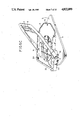
- FIG. 2A a perspective, partially cutaway, view showing a seat cushion of the rotary seat of the present invention, in which a thigh support cushion is pivoted downward;
- FIG. 2B is a similar perspective view showing the same seat cushion, in which a thigh support cushion is pivoted upward;
- FIG. 3 is a schematic view showing a frame structure of the rotary seat of the present invention.
- FIG 4 is a side view showing the same frame structure
- FIG. 5A is a perspective view showing the ordinary position of the rotary seat, in which the thigh support frame is pivoted downward and the turntable is positioned to set the seat frontward;
- FIG. 5B is a perspective view showing the upward pivoted position of the rotary seat, in which only the thigh support frame is pivoted upward from the state shown in FIG. 5A;
- FIG. 5C is a perspective view showing the upward pivoted and turned position of the rotary seat, in which the turntable is turned from the state shown in FIG. 5B, with the thigh support frame kept pivoted upward;
- FIG. 5D is a perspective view showing the reversed position of the rotary seat, in which the thigh support frame is pivoted downward and the turntable is positioned to set the seat rearward;
- FIG. 6 is a perspective view showing a latch mechanism and a release mechanism incorporated in the rotary seat.
- FIG. 7 is an enlarged exploded view of the latch mechanism.
- the first feature of the rotary seat of the present invention is to pivot upward only a part of the seat cushion to prevent the seat from interfering with other adjacent elements when rotated.
- the second feature of the rotary seat of the present invention is to divide the seat cushion into a hip support cushion and a U-shaped thigh support cushion under due consideration of sitting comfort, frame strength, and frame structure simplification, and to pivot upwardly only the divided thigh support cushion before seat rotation.
- the third feature of the rotary seat of the present invention is to provide a latch mechanism for the turntable in such a way as to be released from the floor when only the U-shaped thigh support cushion is pivoted upward before seat rotation.
- FIGS. 1A and 1B show a pair of front seats 1.
- the front seats 1 include a driver's seat 1A and an assistant driver's seat 1B.
- the two seats 1A and 1B are arranged on a floor with a console box 4 (including a shift lever 2 and a hand brake lever 3) intervening between the two seats 1A and 1B.
- Each front seat 1A and 1B is composed of a seat cushion 1a and a seat back 1b arranged at the rear portion of the seat cushion 1a.
- the seat cushion 1a is divided into a hip support cushion 1a-1 mounted on a turntable 5 and a thigh support cushion 1a-2 surrounding the front and both side portions of the hip support cushion 1a-1 and mounted on a thigh support frame 6 (FIG. 2A).
- the thigh support cushion 1a-2 is formed into a roughly U-shape and supported by the thigh support frame 6 pivotally supported via pivotal axles 11 (described later) on both the side portions of the turntable 5.
- the seat cushion is made up of a pad 7 and a decorative material 8 for wrapping the outer surface of the pad 7. Since only the thigh support cushion 1a-2 can be pivoted upward and then rotated as shown in FIG. 1B, it is possible to rotate the seat without interfering with other elements (i.e., the console box 4, the shift lever 2, the hand brake lever 3, etc.)
- the shape of the seat cushion can be partitioned into a hip support cushion for mainly supporting a driver's weight and a thigh support cushion positioned a little higher than the hip support cushion so as to surround the front and both side portions of the hip support cushion. This tendency is prominent, in particular, in bucket type seats, when body weight distribution is taken into account.
- the turntable 5 is rotatably mounted on a base frame 9 fixed to a floor.
- a shallow-cylindrical bearing boss portion 9a is fixed at the center of the base frame 9; and a ring-shaped boss portion 5a fixed to the turntable 5 is rotatably engaged with the bearing boss portion 9a, as depicted in FIG. 5A, in such a way that the ring-shaped boss portion 5a is fitted to the inner circumference of the bearing boss portion 9a.
- some blocks are attached to the under surface of the flange portion of the bearing boss portion 9a to prevent the turntable 5 from being disengaged from the bearing boss portion 9a of the base frame 9.
- the thigh support frame 6 is pivotally supported via two pivotal axles 11 at two supporting portions 5A formed on both side portions of the turntable 5.
- auxiliary frame 12 is provided along the front portion of the frame 6 so as to extend in the width direction of the seat.
- a latch plate 15 is fixed on the upper surface of the ring-shaped boss portion 5a.
- a latch mechanism 16 of the turntable 5 is arranged under this latch plate 15.
- FIGS. 6 and 7 show this latch mechanism 16 for latching the turntable 5 to the bearing boss portion 9a of the base frame 9 by means of a striker 19 at appropriate angular positions at which the rotary seat is fixed.
- the latch mechanism 16 comprises a bracket 17 fixed to the lower surface of the latch plate 15; a shaft 18 pivotally supported by a pair of semicircular pin support portions 17a formed in the bracket 17; a striker 19 slidably inserted into square holes 17A formed in the bracket 17 and under the shaft 18 so as to cross the shaft 18; a pin 20 for connecting the striker 19 to the shaft 18; and a coil spring 21 disposed on the outer circumference of the shaft 18.
- One end of the coil spring 21 is engaged with the pin 20 and the other end thereof is engaged with the semicircular pin support portions 17a, as shown in FIG. 6. Therefore, the shaft 18 is urged in the counterclockwise direction in FIG. 6, so that the striker 19 is urged through the square holes 17A formed in the bracket 17 into engagement with a latch slot LS (shown in FIG. 4) formed in the bearing boss portion 9a of the base frame 9.
- a plurality of latch slots LH (e.g. two) are formed at regular angular intervals (e.g. 180 degrees) along the inner circumference of the bearing boss portion 9a. Therefore, when the striker 19 is engaged with a latch slot LH, the turntable 5 can be latched at the latch position.
- this striker 19 can be disengaged from the latch slot LH when the thigh support frame 1a-2 is pivoted upward.
- one end of a release wire 22 is connected to one end of the striker 19 and the other end of the wire 22 is connected to the lower end of an unlatch arm 23 disposed coaxially with the pivotal axle 11 of the thigh support frame 6, as depicted in FIG. 6.
- This release wire 22 is arranged on the rear part of the seat as shown in FIG. 3. Further, the upper end 23A of the unlatch arm 23 is bent into an L-shape, so as to be stopped by one edge of the thigh support frame 6 when the frame 6 is pivoted upward.
- the striker 19 of the latch mechanism 16 is engaged with a front latch slot LS formed in the bearing boss portion 9a of the base frame 9, as shown in FIGS. 3 and 5A, so that the turntable 5 is fixed to the base frame 9. Further, in this normal position, the auxiliary frame 12 of the thigh support frame 6 is elastically engaged with the engage stopper member 14.
- the auxiliary frame 12 is disengaged from the engage stepper member 14. Since the thigh support frame 6 is pivoted upward, as shown in FIG. 5B, about the pivotal axles 11, the upper end 23A of the unlatch arm 23 is pivoted rearward by the thigh support frame 6 together therewith, as depicted in FIG. 6. Therefore, the release wire 22 is pulled to disengage the striker 19 from the latch slot LS formed in the bearing boss portion 9a of the base frame 9 against an elastic force of the coil spring 21, so that the latch mechanism is released, accompanied with a clicking sound. Therefore, the seat 1 can be rotated freely with the thigh support cushion 1a-2 pivoted upward, without interference with other adjacent elements, as shown in FIG. 5C.
- the seat can be returned from the reverse (rearward) position to the normal (forward) position.
- the present invention is disclosed with respect to its application as an assistant driver's seat for an automotive vehicle. Without being limited thereto, however, it is possible to apply the present invention to any other seats for an automotive vehicle or other vehicles or to other special seats, for instance, those seats whose heights can be adjusted.
- the mechanism of the present invention is easily coupled to a mechanism for adjusting the height of the thigh support frame.
- the seat is divided, it is possible to change the color of the external decorative material of the hip support cushion from that of the thigh support cushion to diversify color variations.
- the seat can be reversed by simply lifting the front edge of the thigh support cushion before turning it, it is possible to prevent the seat from interfering with other adjacent elements when being rotated, in spite of the simplified turning operation.
- the thigh support cushion since only the thigh support cushion is lifted upward, it is possible to simplify the structure of the frame. Further, since the seat cushion is divided into two parts, on the basis of body weight distribution, it is possible to pivot upward only a part of the seat cushion (thigh support cushion) without exerting adverse affects upon sitting comfort. Furthermore, since the latch mechanism of the rotary seat can automatically be released for rotation when only the thigh support cushion is pivoted up, it is possible to turn the seat by a single operation.
Landscapes
- Engineering & Computer Science (AREA)
- Aviation & Aerospace Engineering (AREA)
- Transportation (AREA)
- Mechanical Engineering (AREA)
- Seats For Vehicles (AREA)
Applications Claiming Priority (6)
| Application Number | Priority Date | Filing Date | Title |
|---|---|---|---|
| JP62078378A JPS63242745A (ja) | 1987-03-31 | 1987-03-31 | 回転式シ−トのラツチ機構 |
| JP62-78377 | 1987-03-31 | ||
| JP62078379A JPH0649431B2 (ja) | 1987-03-31 | 1987-03-31 | 車両用シ−ト |
| JP62-78379 | 1987-03-31 | ||
| JP62-78378 | 1987-03-31 | ||
| JP62078377A JPH0649430B2 (ja) | 1987-03-31 | 1987-03-31 | 回転式シ−ト |
Publications (1)
| Publication Number | Publication Date |
|---|---|
| US4822099A true US4822099A (en) | 1989-04-18 |
Family
ID=27302697
Family Applications (1)
| Application Number | Title | Priority Date | Filing Date |
|---|---|---|---|
| US07/175,326 Expired - Fee Related US4822099A (en) | 1987-03-31 | 1988-03-30 | Rotary seat |
Country Status (4)
| Country | Link |
|---|---|
| US (1) | US4822099A (fr) |
| EP (1) | EP0285149B1 (fr) |
| KR (1) | KR910000912B1 (fr) |
| DE (1) | DE3865059D1 (fr) |
Cited By (10)
| Publication number | Priority date | Publication date | Assignee | Title |
|---|---|---|---|---|
| US5127621A (en) * | 1991-12-16 | 1992-07-07 | Milsco Manufacturing Company | Pivotable seat assembly with latch mechanism |
| US5292179A (en) * | 1991-12-10 | 1994-03-08 | Bertrand Faure Automobile "Bfa" | Safety rotary base enabling a rotation over 180 degrees of seat in an automobile vehicle or the like |
| US5544939A (en) * | 1993-05-10 | 1996-08-13 | Cesa- Compagnie Europeenne De Sieges Pour Automobiles | Bucket seat and its application to a land-based motor vehicle |
| US5941498A (en) * | 1996-09-27 | 1999-08-24 | Aisin Seiki Kabushiki Kaisha & Kanto Jidosha Kogyo Kabushiki Kaisha | Rotation mechanism for rotatable seat |
| US6302483B1 (en) * | 1998-11-13 | 2001-10-16 | Alstom Holdings | Revolving seat, in particular for a rail vehicle |
| US6513872B2 (en) * | 2001-05-18 | 2003-02-04 | De Sede Ag | Multipart upholstered furniture |
| USD480241S1 (en) | 2000-11-16 | 2003-10-07 | Autoadapt-Bev Ab | Thigh supporting unit |
| US20090224585A1 (en) * | 2008-03-05 | 2009-09-10 | Lear Corporation | Vehicle seat with a seat tilt adjustment |
| US9511684B2 (en) | 2014-04-25 | 2016-12-06 | Toyota Jidosha Kabushiki Kaisha | Vehicle seat control device and vehicle seat device |
| WO2024124025A1 (fr) * | 2022-12-08 | 2024-06-13 | University Of Pittsburgh - Of The Commonwealth System Of Higher Education | Dispositif de siège de véhicule pour aider à entrer et sortir d'un véhicule |
Families Citing this family (2)
| Publication number | Priority date | Publication date | Assignee | Title |
|---|---|---|---|---|
| FR2676690B1 (fr) * | 1991-05-23 | 1993-09-03 | Faure Bertrand Automobile | Plateau formant base tournante pour siege de vehicule. |
| DE19512284C2 (de) * | 1995-04-04 | 1997-03-20 | Grammer Ag | Fahrzeugsitz, insbesondere Staplersitz |
Citations (10)
| Publication number | Priority date | Publication date | Assignee | Title |
|---|---|---|---|---|
| US2874993A (en) * | 1955-01-17 | 1959-02-24 | Gen Motors Corp | Latch for pivoting seat |
| US3338622A (en) * | 1965-12-08 | 1967-08-29 | Chrysler Corp | Swivel seat for motor vehicle |
| US3550953A (en) * | 1967-08-23 | 1970-12-29 | Hallam Sleigh & Cheston Ltd | Seats |
| US3860283A (en) * | 1973-09-17 | 1975-01-14 | Gen Motors Corp | Swivel seat latch mechanism |
| US4097016A (en) * | 1977-05-12 | 1978-06-27 | Danbar, Inc. | Rotatable seat support assembly |
| US4155593A (en) * | 1978-03-20 | 1979-05-22 | Milsco Manufacturing Company | Vehicle seat having seat rake adjustment means |
| US4231539A (en) * | 1979-04-05 | 1980-11-04 | Leggett & Platt, Incorporated | Pedestal seat base |
| US4401343A (en) * | 1980-03-04 | 1983-08-30 | Audi Nsu Auto Union Aktiengesellschaft | Upholstered seat for motor vehicle |
| US4487452A (en) * | 1981-11-30 | 1984-12-11 | Nissan Motor Company, Limited | Rotatable seat for an automotive vehicle |
| US4522445A (en) * | 1981-12-23 | 1985-06-11 | Keiper Recaro Gmbh & Co. | Vehicle seat, particularly a motor vehicle seat |
Family Cites Families (3)
| Publication number | Priority date | Publication date | Assignee | Title |
|---|---|---|---|---|
| USRE17680E (en) * | 1926-07-14 | 1930-05-27 | Automobile seat and the like | |
| US3066979A (en) * | 1959-08-14 | 1962-12-04 | Rockwell Standard Co | Swivel seat constructions |
| NL6918117A (fr) * | 1969-12-02 | 1971-06-04 |
-
1988
- 1988-03-30 US US07/175,326 patent/US4822099A/en not_active Expired - Fee Related
- 1988-03-30 KR KR1019880003517A patent/KR910000912B1/ko not_active Expired
- 1988-03-30 EP EP88105211A patent/EP0285149B1/fr not_active Expired - Lifetime
- 1988-03-30 DE DE8888105211T patent/DE3865059D1/de not_active Expired - Lifetime
Patent Citations (10)
| Publication number | Priority date | Publication date | Assignee | Title |
|---|---|---|---|---|
| US2874993A (en) * | 1955-01-17 | 1959-02-24 | Gen Motors Corp | Latch for pivoting seat |
| US3338622A (en) * | 1965-12-08 | 1967-08-29 | Chrysler Corp | Swivel seat for motor vehicle |
| US3550953A (en) * | 1967-08-23 | 1970-12-29 | Hallam Sleigh & Cheston Ltd | Seats |
| US3860283A (en) * | 1973-09-17 | 1975-01-14 | Gen Motors Corp | Swivel seat latch mechanism |
| US4097016A (en) * | 1977-05-12 | 1978-06-27 | Danbar, Inc. | Rotatable seat support assembly |
| US4155593A (en) * | 1978-03-20 | 1979-05-22 | Milsco Manufacturing Company | Vehicle seat having seat rake adjustment means |
| US4231539A (en) * | 1979-04-05 | 1980-11-04 | Leggett & Platt, Incorporated | Pedestal seat base |
| US4401343A (en) * | 1980-03-04 | 1983-08-30 | Audi Nsu Auto Union Aktiengesellschaft | Upholstered seat for motor vehicle |
| US4487452A (en) * | 1981-11-30 | 1984-12-11 | Nissan Motor Company, Limited | Rotatable seat for an automotive vehicle |
| US4522445A (en) * | 1981-12-23 | 1985-06-11 | Keiper Recaro Gmbh & Co. | Vehicle seat, particularly a motor vehicle seat |
Cited By (11)
| Publication number | Priority date | Publication date | Assignee | Title |
|---|---|---|---|---|
| US5292179A (en) * | 1991-12-10 | 1994-03-08 | Bertrand Faure Automobile "Bfa" | Safety rotary base enabling a rotation over 180 degrees of seat in an automobile vehicle or the like |
| US5127621A (en) * | 1991-12-16 | 1992-07-07 | Milsco Manufacturing Company | Pivotable seat assembly with latch mechanism |
| US5544939A (en) * | 1993-05-10 | 1996-08-13 | Cesa- Compagnie Europeenne De Sieges Pour Automobiles | Bucket seat and its application to a land-based motor vehicle |
| US5941498A (en) * | 1996-09-27 | 1999-08-24 | Aisin Seiki Kabushiki Kaisha & Kanto Jidosha Kogyo Kabushiki Kaisha | Rotation mechanism for rotatable seat |
| US6302483B1 (en) * | 1998-11-13 | 2001-10-16 | Alstom Holdings | Revolving seat, in particular for a rail vehicle |
| USD480241S1 (en) | 2000-11-16 | 2003-10-07 | Autoadapt-Bev Ab | Thigh supporting unit |
| US6513872B2 (en) * | 2001-05-18 | 2003-02-04 | De Sede Ag | Multipart upholstered furniture |
| US20090224585A1 (en) * | 2008-03-05 | 2009-09-10 | Lear Corporation | Vehicle seat with a seat tilt adjustment |
| US7922230B2 (en) * | 2008-03-05 | 2011-04-12 | Lear Corporation | Vehicle seat with a seat tilt adjustment |
| US9511684B2 (en) | 2014-04-25 | 2016-12-06 | Toyota Jidosha Kabushiki Kaisha | Vehicle seat control device and vehicle seat device |
| WO2024124025A1 (fr) * | 2022-12-08 | 2024-06-13 | University Of Pittsburgh - Of The Commonwealth System Of Higher Education | Dispositif de siège de véhicule pour aider à entrer et sortir d'un véhicule |
Also Published As
| Publication number | Publication date |
|---|---|
| KR880010942A (ko) | 1988-10-25 |
| KR910000912B1 (ko) | 1991-02-18 |
| DE3865059D1 (de) | 1991-10-31 |
| EP0285149A2 (fr) | 1988-10-05 |
| EP0285149A3 (en) | 1989-03-22 |
| EP0285149B1 (fr) | 1991-09-25 |
Similar Documents
| Publication | Publication Date | Title |
|---|---|---|
| US4822099A (en) | Rotary seat | |
| US4491365A (en) | Thigh support adjusting mechanism for vehicle seat | |
| US6047444A (en) | Positive lock armrest mechanism | |
| JP3964172B2 (ja) | 車両用シート | |
| US4487452A (en) | Rotatable seat for an automotive vehicle | |
| JP2979781B2 (ja) | シートのバックル干渉防止装置 | |
| KR100636026B1 (ko) | 차량용 시트의 높이조절기구 | |
| JP3372922B2 (ja) | 自動車用年少者安全座席 | |
| JPH0649431B2 (ja) | 車両用シ−ト | |
| JP3547632B2 (ja) | 自動車のシート装置 | |
| US5150870A (en) | Vehicle seat | |
| KR200386997Y1 (ko) | 차량용 시트의 높이조절기구 | |
| JP3410300B2 (ja) | 自動車用シートクッションのチルトロック機構 | |
| JP3288541B2 (ja) | シートクッションの高さ調整機構 | |
| JP3199353B2 (ja) | 車両のシート配置構造 | |
| JPH0345626Y2 (fr) | ||
| JPS6030103Y2 (ja) | 車両用シ−トのベツト兼用装置 | |
| JPH052123Y2 (fr) | ||
| KR200225552Y1 (ko) | 버스용시트의높이조절장치 | |
| JP2772602B2 (ja) | 乗物用のシート | |
| JPS636379B2 (fr) | ||
| JP3530031B2 (ja) | 自動車のシート装置 | |
| JPS63242745A (ja) | 回転式シ−トのラツチ機構 | |
| JP2026042436A (ja) | 車両用シート | |
| JPH0140757Y2 (fr) |
Legal Events
| Date | Code | Title | Description |
|---|---|---|---|
| AS | Assignment |
Owner name: FUJIKIKO KABUSHIKI KAISHA, 1-13 NIHOMBASHIHONCHO, Free format text: ASSIGNMENT OF ASSIGNORS INTEREST.;ASSIGNORS:NEGI, YOSHITAKA;MATSUURA, HIROSHI;REEL/FRAME:004857/0035 Effective date: 19880322 Owner name: FUJIKIKO KABUSHIKI KAISHA, JAPAN Free format text: ASSIGNMENT OF ASSIGNORS INTEREST;ASSIGNORS:NEGI, YOSHITAKA;MATSUURA, HIROSHI;REEL/FRAME:004857/0035 Effective date: 19880322 |
|
| REMI | Maintenance fee reminder mailed | ||
| LAPS | Lapse for failure to pay maintenance fees | ||
| FP | Lapsed due to failure to pay maintenance fee |
Effective date: 19930418 |
|
| STCH | Information on status: patent discontinuation |
Free format text: PATENT EXPIRED DUE TO NONPAYMENT OF MAINTENANCE FEES UNDER 37 CFR 1.362 |