EP0285149B1 - Siège rotatif - Google Patents
Siège rotatif Download PDFInfo
- Publication number
- EP0285149B1 EP0285149B1 EP88105211A EP88105211A EP0285149B1 EP 0285149 B1 EP0285149 B1 EP 0285149B1 EP 88105211 A EP88105211 A EP 88105211A EP 88105211 A EP88105211 A EP 88105211A EP 0285149 B1 EP0285149 B1 EP 0285149B1
- Authority
- EP
- European Patent Office
- Prior art keywords
- thigh support
- seat
- support frame
- turntable
- cushion
- Prior art date
- Legal status (The legal status is an assumption and is not a legal conclusion. Google has not performed a legal analysis and makes no representation as to the accuracy of the status listed.)
- Expired - Lifetime
Links
Images






Classifications
-
- B—PERFORMING OPERATIONS; TRANSPORTING
- B60—VEHICLES IN GENERAL
- B60N—SEATS SPECIALLY ADAPTED FOR VEHICLES; VEHICLE PASSENGER ACCOMMODATION NOT OTHERWISE PROVIDED FOR
- B60N2/00—Seats specially adapted for vehicles; Arrangement or mounting of seats in vehicles
-
- B—PERFORMING OPERATIONS; TRANSPORTING
- B60—VEHICLES IN GENERAL
- B60N—SEATS SPECIALLY ADAPTED FOR VEHICLES; VEHICLE PASSENGER ACCOMMODATION NOT OTHERWISE PROVIDED FOR
- B60N2/00—Seats specially adapted for vehicles; Arrangement or mounting of seats in vehicles
- B60N2/02—Seats specially adapted for vehicles; Arrangement or mounting of seats in vehicles the seat or part thereof being movable, e.g. adjustable
- B60N2/04—Seats specially adapted for vehicles; Arrangement or mounting of seats in vehicles the seat or part thereof being movable, e.g. adjustable the whole seat being movable
- B60N2/14—Seats specially adapted for vehicles; Arrangement or mounting of seats in vehicles the seat or part thereof being movable, e.g. adjustable the whole seat being movable rotatable, e.g. to permit easy access
- B60N2/146—Seats specially adapted for vehicles; Arrangement or mounting of seats in vehicles the seat or part thereof being movable, e.g. adjustable the whole seat being movable rotatable, e.g. to permit easy access characterised by the locking device
-
- B—PERFORMING OPERATIONS; TRANSPORTING
- B60—VEHICLES IN GENERAL
- B60N—SEATS SPECIALLY ADAPTED FOR VEHICLES; VEHICLE PASSENGER ACCOMMODATION NOT OTHERWISE PROVIDED FOR
- B60N2/00—Seats specially adapted for vehicles; Arrangement or mounting of seats in vehicles
- B60N2/02—Seats specially adapted for vehicles; Arrangement or mounting of seats in vehicles the seat or part thereof being movable, e.g. adjustable
- B60N2/04—Seats specially adapted for vehicles; Arrangement or mounting of seats in vehicles the seat or part thereof being movable, e.g. adjustable the whole seat being movable
- B60N2/14—Seats specially adapted for vehicles; Arrangement or mounting of seats in vehicles the seat or part thereof being movable, e.g. adjustable the whole seat being movable rotatable, e.g. to permit easy access
Definitions
- the present invention relates to a rotary seat and more specifically to a seat rotatable even within a narrow space.
- this rotary seat is suitable for use as an assistant driver's seat for an automotive vehicle, which can be rotated front side back to such a position where the assistant driver can sit facing passengers taking rear seats.
- These rotary seats are mounted on general passenger cars of sedan type.
- a seat cushion is fixed to a turntable, and the turntable can be rotated front side back when a latch mechanism arranged on the turntable is released, to such a position that a passenger taking the rotary seat can sit facing other passengers taking rear seats.
- a rotary seat disposed on the floor comprising turntable means rotatable relative to the floor, thigh support frame means pivotally supported on both sides of said turntable means and hip cushion means disposed on said turntable means for constituting a substantially middle seat cushion. This corresponds to the preamble of claim 1.
- the seat cushion may be designed to lift-up before seat rotation.
- the entire seat cushion must be supported on the turntable via hinges, for instance, there arises another problem in that the seat frame structure is complicated and the rigidity of each part is reduced.
- the turning operation of the rotary seat is complicated and, therefore, troublesome.
- the rotary seat of the present invention comprises thigh support cushion means, disposed on said thigh support frame means, for constituting substantially front and side portions of the seat cushion; when said thigh support frame means is pivoted down, said hip and thigh support cushion means being combined into a single complete seat cushion, and when said thigh support frame means is pivoted up, said thigh support cushion means being separated upward away from said hip support cushion means before seat rotation.
- the rotary seat can be rotated also in a relatively limited space without the necessity of a lift-up of the seat cushion.
- the rotary seat further comprises latch means for latching the turntable means to floor, when said thigh support frame means is pivoted down, with at least two predetermined latch positions: in which the seat can be latched. Furthermore, there provides release means for releasing said latch means from the floor, simultaneously when said thigh support frame means is pivoted up.
- the seat cushion is divided into two, hip support and thigh support, cushions under due consideration of sitting comfort (driver's weight distribution). Further, the hip support cushion is supported on the turntable, and the thigh support cushion is supported on the thigh support frame pivotally supported on both sides of the turntable.
- the first feature of the rotary seat of the present invention is to pivot upward only a part of the seat cushion to prevent the seat from interfering with other, adjacent elements when rotated.
- the second feature of the rotary seat of the present invention is to divide the seat cushion into a hip support cushion and a U-shaped thigh support cushion. under due consideration of sitting comfort, frame strength, and frame structure simplification, and to pivot upwardly only the divided thigh support cushion before seat rotation.
- the third feature of the rotary seat of the present invention is to provide a latch mechanism for the turntable in such a way as to be released from the floor when only the U-shaped thigh support cushion is pivoted upward before seat rotation.
- Figs. 1 A and 1 B show a pair of front seats 1.
- the front seats 1 include a driver's seat 1A and an assistant driver's seat 1 B.
- the two seats 1 A and 1 B are arranged on a floor with a console box 4 (including a shift lever 2 and a hand brake lever 3) intervening between the two seats 1A and 1B.
- Each front seat 1A or 1B is composed of a seat cushion 1 a and a seat back 1 b arranged at the rear portion of the seat cushion 1 a.
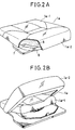
- the seat cushion 1 a is divided into a hip support cushion 1 a-1 mounted on a turntable 5 and a thigh support cushion 1 a-2 surrounding the front and both side portions of the hip support cushion 1a-1 and mounted on a thigh support frame 6 (Fig. 2A).
- the thigh support cushion 1 a-2 is formed into a roughly U-shape and supported by the thigh support frame 6 pivotally supported via pivotal axles 11 (described later) on both the side portions of the turntable 5.
- the seat cushion is made up of a pad 7 and a decorative material 8 for wrapping the outer surface of the pad 7. Since only the thigh support cushion 1 a-2 can be pivoted upward and then rotated as shown in Fig. 1 B, it is possible to rotate the seat without interfering with other elements (i.e., the console box 4, the shift lever 2, the hand brake lever 3, etc.)
- the shape of the seat cushion can be partitioned into a hip support cushion for mainly supporting a driver's weight and a thigh support cushion positioned a little higher than the hip support cushion so as to surround the front and both side portions of the hip support cushion. This tendency is prominent, in particular, in bucket type seats, when body weight distribution is taken into account.
- the turntable 5 is rotatably mounted on a base frame 9 fixed to a floor.
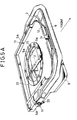
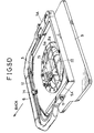
- a shallow-cylindrical bearing boss portion 9a is fixed at the center of the base frame 9; and a ring-shaped boss portion 5a fixed to the turntable 5 is rotatably engaged with the bearing boss portion 9a, as depicted in Fig. 5A, in such a way that the ring-shaped boss portion 5a is fitted to the inner circumference of the bearing boss portion 9a.
- some blocks are attached to the under surface of the flange portion of the bearing boss portion 9a to prevent the turntable 5 from being disengaged from the bearing boss portion 9a of the base frame 9.
- the thigh support frame 6 is pivotally supported via two pivotal axles 11 at two supporting portions 5A formed on both side portions of the turntable 5.
- auxiliary frame 12 is provided along the front portion of the frame 6 so as to extend in the width direction of the seat.
- a latch plate 15 is fixed on the upper surface of the ring-shaped boss portion 5a.
- a latch mechanism 16 of the turntable 5 is arranged under this latch plate 15.
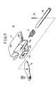
- Figs. 6 and 7 show this latch mechanism 16 for latching the turntable 5 to the bearing boss portion 9a of the base frame 9 by means of a striker 19 at appropriate angular positions at which the rotary seat is fixed.
- the latch mechanism 16 comprises a bracket 17 fixed to the lower surface of the latch plate 15; a shaft 18 pivotally supported by a pair of semicircular pin support portions 17a formed in the bracket 17; a striker 19 slidably inserted into square holes 17A formed in the bracket 17 and under the shaft 18 so as to cross the shaft 18; a pin 20 for connecting the striker 19 to the shaft 18; and a coil spring 21 disposed on the outer circumference of the shaft 18.
- One end of the coil spring 21 is engaged with the pin 20 and the other end thereof is engaged with the semicircular pin support portions 17a, as shown in Fig. 6. Therefore, the shaft 18 is urged in the counterclockwise direction in Fig. 6, so that the striker 19 is urged through the square holes 17A formed in the bracket 17 into engagement with a latch slot LS (shown in Fig. 4) formed in the bearing boss portion 9a of the base frame 9.
- a plurality of latch slots LH (e.g. two) are formed at regular angular intervals (e.g. 180 degrees) along the inner circumference of the bearing boss portion 9a. Therefore, when the striker 19 is engaged with a latch slot LH, the turntable 5 can be latched at the latch position.
- this striker 19 can be disengaged from the latch slot LH when the thigh support frame 1a-2 is pivoted upward.
- one end of a release wire 22 is connected to one end of the striker 19 and the other end of the wire 22 is connected to the lower end of an unlatch arm 23 disposed coaxially with the pivotal axle 11 of the thigh support frame 6, as depicted in Fig. 6.
- This release wire 22 is arranged on the rear part of the seat as shown in Fig. 3. Further, the upper end 23A of the unlatch arm 23 is bent into an L-shape, so as to be stopped by one edge of the thigh support frame 6 when the frame 6 is pivoted upward.
- the striker 19 of the latch mechanism 16 is engaged with a front latch slot LS formed in the bearing boss portion 9a of the base frame 9, as shown in Figs. 3 and 5A, so that the turntable 5 is fixed to the base frame 9. Further, in this normal position, the auxiliary frame 12 of the thigh support frame 6 is elastically engaged with the engage stopper member 14.
- the auxiliary frame 12 is disengaged from the engage stopper member 14. Since the thigh support frame 6 is pivoted upward, as shown in Fig. 5B, about the pivotal axles 11, the upper end 23A of the unlatch arm 23 is pivoted rearward by the thigh support frame 6 together therewith, as depicted in Fig. 6. Therefore, the release wire 22 is pulled to disengage the striker 19 from the latch slot LS formed in the bearing boss portion 9a of the base frame 9 against an elastic force of the coil spring 21, so that the latch mechanism is released, accompanied with a clicking sound. Therefore, the seat 1 can be rotated freely with the thigh support cushion 1 a-2 pivoted upward, without interference with other adjacent elements, as shown in Fig. 5C.
- the seat can be returned from the reverse (rearward) position to the normal (forward) position.
- the present invention is disclosed with respect to its application as an assistant driver's seat for an automotive vehicle. Without being limited thereto, however, it is possible to apply the present invention to any other seats for an automotive vehicle or other vehicles or to other special seats, for instance, those seats whose heights can be adjusted.
- the mechanism of the present invention is easily coupled to a mechanism for adjusting the height of the thigh support frame.
- the seat is divided, it is possible to change the color of the external decorative material of the hip support cushion from that of the thigh support cushion to diversify color variations.
- the seat can be reversed front side back by simply lifting the front edge of the thigh support cushion before turning it, it is possible to prevent the seat from interfering with other adjacent elements when being rotated, in spite of the simplified turning operation.
- the thigh support cushion since only the thigh support cushion is lifted upward, it is possible to simplify the structure of the frame. Further, since the seat cushion is divided into two, on the basis of body weight distribution, it is possible to pivot upward only a part of the seat cushion (thigh support cushion) without exerting adverse affects upon sitting comfort. Furthermore, since the latch mechanism of the rotary seat can automatically be released for rotation when only the thigh support cushion is pivoted up, it is possible to turn the seat by a single operation.
Landscapes
- Engineering & Computer Science (AREA)
- Aviation & Aerospace Engineering (AREA)
- Transportation (AREA)
- Mechanical Engineering (AREA)
- Seats For Vehicles (AREA)
Claims (6)
caractérisé par
Applications Claiming Priority (6)
| Application Number | Priority Date | Filing Date | Title |
|---|---|---|---|
| JP78377/87 | 1987-03-31 | ||
| JP78379/87 | 1987-03-31 | ||
| JP62078379A JPH0649431B2 (ja) | 1987-03-31 | 1987-03-31 | 車両用シ−ト |
| JP62078377A JPH0649430B2 (ja) | 1987-03-31 | 1987-03-31 | 回転式シ−ト |
| JP78378/87 | 1987-03-31 | ||
| JP62078378A JPS63242745A (ja) | 1987-03-31 | 1987-03-31 | 回転式シ−トのラツチ機構 |
Publications (3)
| Publication Number | Publication Date |
|---|---|
| EP0285149A2 EP0285149A2 (fr) | 1988-10-05 |
| EP0285149A3 EP0285149A3 (en) | 1989-03-22 |
| EP0285149B1 true EP0285149B1 (fr) | 1991-09-25 |
Family
ID=27302697
Family Applications (1)
| Application Number | Title | Priority Date | Filing Date |
|---|---|---|---|
| EP88105211A Expired - Lifetime EP0285149B1 (fr) | 1987-03-31 | 1988-03-30 | Siège rotatif |
Country Status (4)
| Country | Link |
|---|---|
| US (1) | US4822099A (fr) |
| EP (1) | EP0285149B1 (fr) |
| KR (1) | KR910000912B1 (fr) |
| DE (1) | DE3865059D1 (fr) |
Families Citing this family (12)
| Publication number | Priority date | Publication date | Assignee | Title |
|---|---|---|---|---|
| FR2676690B1 (fr) * | 1991-05-23 | 1993-09-03 | Faure Bertrand Automobile | Plateau formant base tournante pour siege de vehicule. |
| FR2684609B1 (fr) * | 1991-12-10 | 1994-02-11 | Faure Automobile Bertrand | Base tournante a securite permettant la rotation de 180degre d'un siege dans un vehicule automobile ou analogue. |
| US5127621A (en) * | 1991-12-16 | 1992-07-07 | Milsco Manufacturing Company | Pivotable seat assembly with latch mechanism |
| FR2705067B1 (fr) * | 1993-05-10 | 1995-08-18 | Cesa | Siege enveloppant et son application a un vehicule automobile terrestre. |
| DE19512284C2 (de) * | 1995-04-04 | 1997-03-20 | Grammer Ag | Fahrzeugsitz, insbesondere Staplersitz |
| JP3431773B2 (ja) * | 1996-09-27 | 2003-07-28 | アイシン精機株式会社 | 車両用回転式シート装置 |
| FR2785862B1 (fr) * | 1998-11-13 | 2003-05-16 | Alstom Technology | Siege tournant, notamment pour vehicule ferroviaire |
| USD480241S1 (en) | 2000-11-16 | 2003-10-07 | Autoadapt-Bev Ab | Thigh supporting unit |
| US6513872B2 (en) * | 2001-05-18 | 2003-02-04 | De Sede Ag | Multipart upholstered furniture |
| DE102008012597A1 (de) * | 2008-03-05 | 2009-09-10 | Lear Corporation, Southfield | Fahrzeugsitz mit Sitzkippeinstellung |
| JP6121940B2 (ja) | 2014-04-25 | 2017-04-26 | トヨタ自動車株式会社 | 車両用シート制御装置及び車両用シート装置 |
| WO2024124025A1 (fr) * | 2022-12-08 | 2024-06-13 | University Of Pittsburgh - Of The Commonwealth System Of Higher Education | Dispositif de siège de véhicule pour aider à entrer et sortir d'un véhicule |
Family Cites Families (13)
| Publication number | Priority date | Publication date | Assignee | Title |
|---|---|---|---|---|
| USRE17680E (en) * | 1926-07-14 | 1930-05-27 | Automobile seat and the like | |
| US2874993A (en) * | 1955-01-17 | 1959-02-24 | Gen Motors Corp | Latch for pivoting seat |
| US3066979A (en) * | 1959-08-14 | 1962-12-04 | Rockwell Standard Co | Swivel seat constructions |
| US3338622A (en) * | 1965-12-08 | 1967-08-29 | Chrysler Corp | Swivel seat for motor vehicle |
| GB1168927A (en) * | 1967-08-23 | 1969-10-29 | Hallam Sleigh & Cheston Ltd | Improvements relating to Seats |
| NL6918117A (fr) * | 1969-12-02 | 1971-06-04 | ||
| US3860283A (en) * | 1973-09-17 | 1975-01-14 | Gen Motors Corp | Swivel seat latch mechanism |
| US4097016A (en) * | 1977-05-12 | 1978-06-27 | Danbar, Inc. | Rotatable seat support assembly |
| US4155593A (en) * | 1978-03-20 | 1979-05-22 | Milsco Manufacturing Company | Vehicle seat having seat rake adjustment means |
| US4231539A (en) * | 1979-04-05 | 1980-11-04 | Leggett & Platt, Incorporated | Pedestal seat base |
| DE3008179C2 (de) * | 1980-03-04 | 1986-07-31 | Audi AG, 8070 Ingolstadt | Polstersitz für ein Kraftfahrzeug |
| US4487452A (en) * | 1981-11-30 | 1984-12-11 | Nissan Motor Company, Limited | Rotatable seat for an automotive vehicle |
| DE3274633D1 (en) * | 1981-12-23 | 1987-01-22 | Keiper Recaro Gmbh Co | Vehicle seat |
-
1988
- 1988-03-30 KR KR1019880003517A patent/KR910000912B1/ko not_active Expired
- 1988-03-30 US US07/175,326 patent/US4822099A/en not_active Expired - Fee Related
- 1988-03-30 EP EP88105211A patent/EP0285149B1/fr not_active Expired - Lifetime
- 1988-03-30 DE DE8888105211T patent/DE3865059D1/de not_active Expired - Lifetime
Also Published As
| Publication number | Publication date |
|---|---|
| EP0285149A2 (fr) | 1988-10-05 |
| KR880010942A (ko) | 1988-10-25 |
| US4822099A (en) | 1989-04-18 |
| EP0285149A3 (en) | 1989-03-22 |
| DE3865059D1 (de) | 1991-10-31 |
| KR910000912B1 (ko) | 1991-02-18 |
Similar Documents
| Publication | Publication Date | Title |
|---|---|---|
| US4491365A (en) | Thigh support adjusting mechanism for vehicle seat | |
| US4822099A (en) | Rotary seat | |
| JP3964172B2 (ja) | 車両用シート | |
| US4487452A (en) | Rotatable seat for an automotive vehicle | |
| JP2001130294A (ja) | 車両用シート | |
| KR100636026B1 (ko) | 차량용 시트의 높이조절기구 | |
| JP2005034327A (ja) | 車両用シート | |
| KR200386997Y1 (ko) | 차량용 시트의 높이조절기구 | |
| JP2533942Y2 (ja) | シート | |
| JPH0649431B2 (ja) | 車両用シ−ト | |
| US5150870A (en) | Vehicle seat | |
| JP3199353B2 (ja) | 車両のシート配置構造 | |
| JP3288541B2 (ja) | シートクッションの高さ調整機構 | |
| JP3547632B2 (ja) | 自動車のシート装置 | |
| JP3410300B2 (ja) | 自動車用シートクッションのチルトロック機構 | |
| KR200225552Y1 (ko) | 버스용시트의높이조절장치 | |
| JPH0345626Y2 (fr) | ||
| JPS6030103Y2 (ja) | 車両用シ−トのベツト兼用装置 | |
| JPH11206509A (ja) | 車両用アームレスト構造 | |
| JPH0140757Y2 (fr) | ||
| JPH0260534B2 (fr) | ||
| JPH0577538B2 (fr) | ||
| JP3102306B2 (ja) | シート装置 | |
| JPS63242745A (ja) | 回転式シ−トのラツチ機構 | |
| JP2007105101A (ja) | アームレスト装置 |
Legal Events
| Date | Code | Title | Description |
|---|---|---|---|
| PUAI | Public reference made under article 153(3) epc to a published international application that has entered the european phase |
Free format text: ORIGINAL CODE: 0009012 |
|
| 17P | Request for examination filed |
Effective date: 19880330 |
|
| AK | Designated contracting states |
Kind code of ref document: A2 Designated state(s): DE FR GB |
|
| PUAL | Search report despatched |
Free format text: ORIGINAL CODE: 0009013 |
|
| AK | Designated contracting states |
Kind code of ref document: A3 Designated state(s): DE FR GB |
|
| 17Q | First examination report despatched |
Effective date: 19900606 |
|
| GRAA | (expected) grant |
Free format text: ORIGINAL CODE: 0009210 |
|
| AK | Designated contracting states |
Kind code of ref document: B1 Designated state(s): DE FR GB |
|
| REF | Corresponds to: |
Ref document number: 3865059 Country of ref document: DE Date of ref document: 19911031 |
|
| ET | Fr: translation filed | ||
| PLBI | Opposition filed |
Free format text: ORIGINAL CODE: 0009260 |
|
| 26 | Opposition filed |
Opponent name: DEUTSCHE AIRBUS GMBH ABT. GZ 13 BRE Effective date: 19920527 |
|
| PLBN | Opposition rejected |
Free format text: ORIGINAL CODE: 0009273 |
|
| STAA | Information on the status of an ep patent application or granted ep patent |
Free format text: STATUS: OPPOSITION REJECTED |
|
| 27O | Opposition rejected |
Effective date: 19930802 |
|
| PGFP | Annual fee paid to national office [announced via postgrant information from national office to epo] |
Ref country code: GB Payment date: 19960219 Year of fee payment: 9 |
|
| PGFP | Annual fee paid to national office [announced via postgrant information from national office to epo] |
Ref country code: FR Payment date: 19960226 Year of fee payment: 9 |
|
| PGFP | Annual fee paid to national office [announced via postgrant information from national office to epo] |
Ref country code: DE Payment date: 19960430 Year of fee payment: 9 |
|
| PG25 | Lapsed in a contracting state [announced via postgrant information from national office to epo] |
Ref country code: GB Effective date: 19970330 |
|
| GBPC | Gb: european patent ceased through non-payment of renewal fee |
Effective date: 19970330 |
|
| PG25 | Lapsed in a contracting state [announced via postgrant information from national office to epo] |
Ref country code: FR Free format text: LAPSE BECAUSE OF NON-PAYMENT OF DUE FEES Effective date: 19971128 |
|
| PG25 | Lapsed in a contracting state [announced via postgrant information from national office to epo] |
Ref country code: DE Effective date: 19971202 |
|
| REG | Reference to a national code |
Ref country code: FR Ref legal event code: ST |