US4966700A - Apparatus for separating into its two phases a substance consisting of solid matter suspended in a liquid - Google Patents
Apparatus for separating into its two phases a substance consisting of solid matter suspended in a liquid Download PDFInfo
- Publication number
- US4966700A US4966700A US07/367,039 US36703989A US4966700A US 4966700 A US4966700 A US 4966700A US 36703989 A US36703989 A US 36703989A US 4966700 A US4966700 A US 4966700A
- Authority
- US
- United States
- Prior art keywords
- internal
- solid matter
- external
- enclosure
- liquid
- Prior art date
- Legal status (The legal status is an assumption and is not a legal conclusion. Google has not performed a legal analysis and makes no representation as to the accuracy of the status listed.)
- Expired - Fee Related
Links
- 239000007787 solid Substances 0.000 title claims abstract description 46
- 239000000126 substance Substances 0.000 title claims abstract description 34
- 239000007788 liquid Substances 0.000 title claims abstract description 32
- 239000012528 membrane Substances 0.000 claims abstract description 20
- 238000004140 cleaning Methods 0.000 claims description 20
- 239000012530 fluid Substances 0.000 claims description 13
- 230000009471 action Effects 0.000 claims description 6
- 230000000295 complement effect Effects 0.000 claims description 5
- 238000006073 displacement reaction Methods 0.000 claims description 5
- 238000007789 sealing Methods 0.000 claims description 5
- 238000005192 partition Methods 0.000 claims description 2
- 238000003825 pressing Methods 0.000 claims description 2
- 230000002093 peripheral effect Effects 0.000 claims 3
- 238000012163 sequencing technique Methods 0.000 claims 1
- 238000000034 method Methods 0.000 description 11
- 230000002787 reinforcement Effects 0.000 description 5
- 239000000654 additive Substances 0.000 description 4
- 239000008187 granular material Substances 0.000 description 4
- 238000012423 maintenance Methods 0.000 description 3
- 229910052751 metal Inorganic materials 0.000 description 3
- 239000002184 metal Substances 0.000 description 3
- 238000000926 separation method Methods 0.000 description 3
- 238000003466 welding Methods 0.000 description 3
- 235000008733 Citrus aurantifolia Nutrition 0.000 description 2
- XEEYBQQBJWHFJM-UHFFFAOYSA-N Iron Chemical compound [Fe] XEEYBQQBJWHFJM-UHFFFAOYSA-N 0.000 description 2
- 235000011941 Tilia x europaea Nutrition 0.000 description 2
- 230000000996 additive effect Effects 0.000 description 2
- 238000013459 approach Methods 0.000 description 2
- 230000008901 benefit Effects 0.000 description 2
- 230000008859 change Effects 0.000 description 2
- 238000007599 discharging Methods 0.000 description 2
- 230000000694 effects Effects 0.000 description 2
- 230000005484 gravity Effects 0.000 description 2
- 239000004571 lime Substances 0.000 description 2
- 238000011089 mechanical engineering Methods 0.000 description 2
- 238000000746 purification Methods 0.000 description 2
- 230000009467 reduction Effects 0.000 description 2
- 230000008439 repair process Effects 0.000 description 2
- 239000010865 sewage Substances 0.000 description 2
- XLYOFNOQVPJJNP-UHFFFAOYSA-N water Substances O XLYOFNOQVPJJNP-UHFFFAOYSA-N 0.000 description 2
- 241000501667 Etroplus Species 0.000 description 1
- WSFSSNUMVMOOMR-UHFFFAOYSA-N Formaldehyde Chemical compound O=C WSFSSNUMVMOOMR-UHFFFAOYSA-N 0.000 description 1
- 230000003213 activating effect Effects 0.000 description 1
- 230000006978 adaptation Effects 0.000 description 1
- 238000004026 adhesive bonding Methods 0.000 description 1
- 230000001174 ascending effect Effects 0.000 description 1
- 230000005540 biological transmission Effects 0.000 description 1
- AXCZMVOFGPJBDE-UHFFFAOYSA-L calcium dihydroxide Chemical compound [OH-].[OH-].[Ca+2] AXCZMVOFGPJBDE-UHFFFAOYSA-L 0.000 description 1
- 239000000920 calcium hydroxide Substances 0.000 description 1
- 235000011116 calcium hydroxide Nutrition 0.000 description 1
- 239000003795 chemical substances by application Substances 0.000 description 1
- 238000005352 clarification Methods 0.000 description 1
- 235000013365 dairy product Nutrition 0.000 description 1
- 238000013461 design Methods 0.000 description 1
- 239000003599 detergent Substances 0.000 description 1
- 238000010586 diagram Methods 0.000 description 1
- 238000001035 drying Methods 0.000 description 1
- 239000003337 fertilizer Substances 0.000 description 1
- 239000000945 filler Substances 0.000 description 1
- 239000008394 flocculating agent Substances 0.000 description 1
- 238000005189 flocculation Methods 0.000 description 1
- 230000016615 flocculation Effects 0.000 description 1
- 235000013305 food Nutrition 0.000 description 1
- 239000008098 formaldehyde solution Substances 0.000 description 1
- 238000004108 freeze drying Methods 0.000 description 1
- 239000000446 fuel Substances 0.000 description 1
- 239000007789 gas Substances 0.000 description 1
- 238000002309 gasification Methods 0.000 description 1
- 238000009776 industrial production Methods 0.000 description 1
- 229910052500 inorganic mineral Inorganic materials 0.000 description 1
- 238000009434 installation Methods 0.000 description 1
- 229910052742 iron Inorganic materials 0.000 description 1
- 239000000463 material Substances 0.000 description 1
- 239000011707 mineral Substances 0.000 description 1
- 235000010755 mineral Nutrition 0.000 description 1
- 229920000642 polymer Polymers 0.000 description 1
- 239000011148 porous material Substances 0.000 description 1
- 230000003449 preventive effect Effects 0.000 description 1
- 230000008569 process Effects 0.000 description 1
- 238000005086 pumping Methods 0.000 description 1
- 238000000197 pyrolysis Methods 0.000 description 1
- 239000010802 sludge Substances 0.000 description 1
- 239000011343 solid material Substances 0.000 description 1
- 229920002994 synthetic fiber Polymers 0.000 description 1
- 238000013519 translation Methods 0.000 description 1
- 238000009423 ventilation Methods 0.000 description 1
- 238000005406 washing Methods 0.000 description 1
- 239000002351 wastewater Substances 0.000 description 1
Images


Classifications
-
- B—PERFORMING OPERATIONS; TRANSPORTING
- B30—PRESSES
- B30B—PRESSES IN GENERAL
- B30B9/00—Presses specially adapted for particular purposes
- B30B9/02—Presses specially adapted for particular purposes for squeezing-out liquid from liquid-containing material, e.g. juice from fruits, oil from oil-containing material
- B30B9/22—Presses specially adapted for particular purposes for squeezing-out liquid from liquid-containing material, e.g. juice from fruits, oil from oil-containing material using a flexible member, e.g. diaphragm, urged by fluid pressure
- B30B9/225—Presses specially adapted for particular purposes for squeezing-out liquid from liquid-containing material, e.g. juice from fruits, oil from oil-containing material using a flexible member, e.g. diaphragm, urged by fluid pressure the diaphragm being tubular
-
- B—PERFORMING OPERATIONS; TRANSPORTING
- B01—PHYSICAL OR CHEMICAL PROCESSES OR APPARATUS IN GENERAL
- B01D—SEPARATION
- B01D29/00—Filters with filtering elements stationary during filtration, e.g. pressure or suction filters, not covered by groups B01D24/00 - B01D27/00; Filtering elements therefor
- B01D29/11—Filters with filtering elements stationary during filtration, e.g. pressure or suction filters, not covered by groups B01D24/00 - B01D27/00; Filtering elements therefor with bag, cage, hose, tube, sleeve or like filtering elements
- B01D29/13—Supported filter elements
- B01D29/15—Supported filter elements arranged for inward flow filtration
-
- B—PERFORMING OPERATIONS; TRANSPORTING
- B01—PHYSICAL OR CHEMICAL PROCESSES OR APPARATUS IN GENERAL
- B01D—SEPARATION
- B01D29/00—Filters with filtering elements stationary during filtration, e.g. pressure or suction filters, not covered by groups B01D24/00 - B01D27/00; Filtering elements therefor
- B01D29/76—Handling the filter cake in the filter for purposes other than for regenerating
- B01D29/80—Handling the filter cake in the filter for purposes other than for regenerating for drying
- B01D29/82—Handling the filter cake in the filter for purposes other than for regenerating for drying by compression
- B01D29/822—Handling the filter cake in the filter for purposes other than for regenerating for drying by compression using membranes
Definitions
- the present invention relates to the treatment of substances and, more particularly, to the treatment of substances consisting of solid matter suspended in a liquid.
- the invention relates more especially to the separation, into its two phases, of a substance consisting of solid matter suspended in a liquid.
- This type of problem is encountered, for example in food industries such as the dairy, brewing and wine industries. This problem is also encountered to a greater extent downstream in industrial production processes when the waste water and effluents, for example of urban sewage purification plants, must be treated.
- This document describes an apparatus which comprises essentially an external group or unit and an internal group or unit which are movable relative to each other and which define a chamber and an enclosure separated by a body which is permeable with respect to liquid and impermeable with respect to solid matter.
- An impervious elastic membrane which can be expanded, is arranged so as to enable reduction of the volume of the enclosure in order to expel the liquid of the substance to be treated which has been placed inside the chamber and in order to press the solid matte against the body from where it is detached by a scraper so as to be collected separately.
- the dry-matter content of the mass obtained varies from 20 to 25% at the most.
- the dry-matter content may be improved by adding a chemical additive, for example lime or a calcium hydrate, to the substance to be treated: in this case a content of about 35% is achieved.
- the flocculating agent which is very often an organic molecule for example a polymer or a formaldehyde solution, is rapidly destroyed either by the temperature or by the mechanical forces if the solid mass is subjected to a compressive force in order to expel more liquid therefrom.
- the object of the present invention is to overcome these drawbacks by the almost continuous treatment of substances so as to obtain a dry-matter content which approaches or even exceeds 50% by weight for the solid matter collected, even when there is no chemical additive.
- the invention relates to an apparatus for separating into its two phases a substance consisting of solid matter suspended in a liquid and for recovering them separately in the compacted solid state with a high dry-matter content and in the liquid state practically free from solid matter, which comprises, among other things, an external group or unit and an internal group or unit, with symmetry of revolution, which are movable relative to each other and which define a chamber and an enclosure separated by a body permeable with respect to the liquid and impermeable with respect to the solid matter, and which comprises an impervious elastic membrane, which can be expanded, arranged so as to enable reduction of the volume of the enclosure in order to expel the liquid of the substance to be treated which has been placed inside the chamber and in order to press the solid matter against the body, and which comprises a scraper for detaching, if necessary, the solid matter pressed against the body so that it can be collected separately.
- the apparatus according to the invention is characterized in that it comprises a central guide for directing the relative displacements of the external and internal groups and a hopper for supplying substance to be treated, which is mounted on top of the external group to which it is fixed and which is closed at its bottom by a closing device centred on the guide.
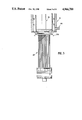
- FIG. 1 is a view, partially in meridian section, of an embodiment of an apparatus according to the invention
- FIG. 2 is a view, in meridian section, of the internal group of the apparatus according to the invention and illustrated in FIG. 1;
- FIG. 3 is a view similar to that of FIG. 1 in which the apparatus is shown in a position where the internal and external groups are disengaged from each other without the actuating device being shown;
- FIG. 4 is a view similar to that of FIG. 3 in another relative position of the external and internal groups of the apparatus according to FIG. 1;
- FIGS. 5A and 5B are detailed partial sections through embodiments of the seals which ensure a sealing action between the external and internal groups of the apparatus according to the invention
- FIG. 6 is a partial detailed section through an embodiment of a filter for the apparatus according to the invention which is in the form of an interchangeable cartridge;
- FIG. 7 is a detailed view of an embodiment of a solenoid valve of the discharge duct of the chamber of the apparatus according to the invention.
- FIGS. 8A, 8B and 8C are various detailed views of the arrangement for cleaning the apparatus according to the invention.
- FIG. 9 is an illustration of an embodiment of a device for actuating the apparatus according to the invention so as to cause relative displacements of the internal and external groups.
- FIG. 10 is a view of another variation of embodiment of the device for actuating the apparatus according to the invention.
- an apparatus for separating into its two phases a substance consisting of solid matter suspended in a liquid and for recovering them separately in a solid state with a high dry-matter content and a liquid state practically free from solid matter, comprises, among other things, an external group or unit 10 and an internal group or unit 20.
- This apparatus comprises also a guide 30, a hopper 40, a scraper 50, an actuating device 60, a cleaning arrangement 70, discharge ducts 80 and means for controlling and supplying fluids 90.
- the external group 10 comprises a body 11 made for example from thick sheet metal with holes 110 formed in it.
- a collar 14 is fixed at each of the ends of the body 11, for example by means of welding. These collars hold between them a casing 12 and a cover 13 by means of reinforcements 15 which are for example bolted or screwed, as illustrated schematically.
- the collars have an annular shape and square cross-section and the reinforcements are in the form of annuli, as can be seen clearly from the drawings.
- the internal group 20 comprises a tube 21 at each of the ends of which there are fixed circular rims 23. Between these circular rims there is located a skirting 22 coaxial with the tube 21.
- Each of the circular rims has a flange 24 with which a counter-flange 25 is associated.
- Each of these flanges 24 has, towards the outside, a collar plate 26.
- the bottom collar plate 26 also has a sleeve 27.
- the upper and lower flanges 24 and counter-flanges 25 are identical and each have conical complementary flanks 240 and 250, respectively. Between these flanks there is located an elastic membrane 220. It will be understood that by adjusting the clamping force of the fixing nuts, it is possible to move closer together the complementary conical flanks located opposite each other and thus both fix and tension the elastic membrane 220.
- the elastic membrane 220 has external channels 221 and is covered on its external surface with an elastic mesh 222 for reasons which will be explained below.
- These membranes and meshes are made, for example, from suitable commercial synthetic materials.
- seals 29 are located on the periphery of the counter-flanges 25 and the sleeve 27.
- these seals preferably have at least one protrusion 295, for example in the form of a dovetail, which is engaged in a recess 296 of complementary shape.
- the protrusion is also glued or otherwise fixed in any suitable appropriate manner to the corresponding recess in order to complete the joint and, if necessary, ensure fluid-tightness for the reason which will be understood below.
- each groove 292 there leads at least one pipe arrangement 293 provided with suitable solenoid valve(s) 294.
- the solenoid valves are governed by the control means 90.
- a scraper 50 is provided on the internal group 20.
- This scraper consists of an edge 51 of the counter-flange 25 which is inclined in the form of an undercut, as illustrated, for example with an angle of about 15°.
- the apparatus according to the invention also comprises a guide 30.
- This guide consists of a column 31 and the internal wall 32 of the tube 21 which is able to slide against the external wall of the column.
- the internal and external groups possess symmetry of revolution, for example cylindrical in general, and are engaged one inside the other so as to be coaxial. This can be seen clearly from examining FIGS. 1 to 4 in particular; tube 21 and column 31 are arranged as illustrated such that the internal group and external group are able to move relative to each other, in translation, along their axis of symmetry.
- the apparatus according to the invention also comprises a hopper 40.
- This hopper consists, essentially, of a vessel 41 which has a funnel-shaped bottom 42 in the centre of which a closing device 43 is located.
- This closing device comprises a valve 430, which is for example bell-shaped, provided with a shoulder 431 intended to cooperate with a seat 432, for example formed in the top of one of the collars 14 or mounted on the latter. Where required, a seal is interposed.
- valve is mounted movably on the column which passes through it and is able to move by sliding on the latter so as to be able to cover or uncover an annular orifice 433 which the shoulder 431 and the seat 432 define.
- a suitable seal not shown, ensures a sealing action between column 31 and valve 430 without impeding their relative movements.
- the movements of the valve 430 are controlled by those of the internal group 20 so as to allow filling of the enclosure 223 with substance to be treated.
- An actuating device 60 is inserted between the external group 10 and the internal group 20 so as to move them relative to each other.
- this device consists of a pneumatic or hydraulic jack for example, with a plunger 61 and a cylinder 62 which are connected to the external group 10 and to the internal group 20, respectively, as can be seen more clearly by examining FIGS. 9 and 10.
- the manner in which the join between jack and group is effected is conventional.
- This actuating device 60 is governed by the control means 90.
- the chamber 17 is divided into compartments 173 above which dividers 170 are located.
- dividers consist, for example, of separate partitions 171 kept at a distance from each other by struts 172.
- These dividers made of suitable material are fixed onto the body 11 for example by means of welding.
- seals 174 On the struts there are arranged, where required, seals 174, not shown in detail so as not to overload the drawing, for example of the same type as those described above, so as to be able to isolate, if necessary, the compartments from each other for the reasons which will be understood below.
- the seals cooperate with the casing 12 which is located opposite them. If necessary, these seals are also governed by the control means 90.
- the apparatus according to the invention also comprises a cleaning arrangement 70 shown in particular in FIGS. 8.
- This cleaning arrangement consists, for example, of ultrasonic generators 71 which are fixed on the casing 12, using any suitable method for example gluing. In this case, a polygonal casing is used. The arrangement and tiering of these generators 71 are clearly illustrated in FIGS. 8A and 8B. These generators 71 are protected by the cover 13 which is joined by any suitable method in a sealed manner to one of the reinforcements 15.
- the cleaning arrangement also comprises, if necessary, nozzles 72, which are provided at the end of connection pipes 73, as illustrated in particular in FIG. 8C, provided with solenoid valves 74.
- FIG. 8C shows an embodiment where the nozzles 72 are arranged inside the upper counter-flange 25 of the internal group 20 in the case of a split seal 29.
- nozzles are located at regular intervals. It is also possible to use other nozzles 720 located underneath the bottom collar 14 of the external group 10, on the periphery of the internal group 20. These nozzles 720 are provided, for example, inside a hollow circle fixed in a suitable manner to the collar for example. This is shown very schematically in particular in FIG. 1.
- nozzles are supplied with fluid by means of solenoid valves 74 governed by control means 90.
- Pressurized water to which detergents have been added, is used for example. Reference will be made again below to the cleaning arrangement.
- the apparatus according to the invention is also equipped with at least one duct 80 for discharging in particular liquid separated from the substance to be treated.
- This duct is provided with a solenoid valve 81 governed by the control means 90.
- control means 90 operate in particular the actuating means 60 and the solenoid valves already mentioned, as will be understood below, in order to ensure the correct sequence of the various operating phases of the apparatus according to the invention.
- control means 90 are, for example, a programmable microcomputer. It is clear that it is also possible to use relays and cams driven by a suitable servomechanism; this is conventional.
- the body 11 is also provided with a filter 16 which is preferably in the form of an interchangeable cartridge.
- This filter 16 (FIG. 6), with a configuration of revolution, comprises a screen 160 behind which there is located a meshed network 161 such as a grid serving as a mechanical support in particular.
- the screen and the network are joined by end rings 162 which are mounted as illustrated in detail in FIG. 6, for example by means of screws 163 with a sunken milled head, engaged inside a reinforcement.
- a given play is provided between the periphery of the collars and that, located opposite, of the counter-flanges; these peripheries are smooth and no projection exists there except when the dilatable seals expand and thus take up this play.
- the filter and the scraper allows the scraper to pass into the vicinity of the actual screen.
- the rings of the filter are slightly set back or at the most lie flush with the periphery of the corresponding collars.
- external group and internal group are able to slide freely relative to each other without difficulty since they are directed by the guide.
- the apparatus is in the position shown in FIG. 1.
- the hopper 40 is full of substances to be treated, the solid matter of which must be separated from the liquid in which they are suspended.
- the control means 90 are activated. They operate the solenoid valves, in particular that 81 of the discharge duct 80 so as to open it, as well as the solenoid valves 294 of the piping 293 so that the seals 29 of the counter-flanges 25 remain in the rest condition.
- the seals thus occupy the position illustrated in continuous lines in FIGS. 5A and 5B; a sealing action is therefore not ensured between internal group and external group which are free to move without obstruction.
- the actuating device 60 is operated and causes the internal group to slide relative to the external group, as illustrated in FIG. 4.
- the closing device 43 is open, the internal group raising the valve and the substance to be treated thus fills the enclosure 223 by means of gravity. Gradually as it is introduced, liquid is separated spontaneously from the solid matter of the substance to be treated passing through the filter 16 and flowing into the chamber 17.
- the control means 90 operate again the actuating device 60 so as to reposition the apparatus in the position in which it is illustrated in FIG. 1.
- the seals 29 are then inflated, the control means 90 operate the solenoid valves 294 of the piping 293, so as to dilate the said seals as illustrated in broken lines in FIG. 5A and 5B and ensure a sealing action between the counter-flanges 25 and the collars 14, both top and bottom, of the internal and external groups.
- the control means 90 then operate the solenoid valve 225 of the conduit 224 so as to blow in pressurized fluid, for example compressed air in order to dilate the elastic membrane 220.
- pressurized fluid for example compressed air
- the latter swells and forces the liquid of the substance to be treated from the enclosure 223 into the chamber 17, while pressing the solid matter against the filter 16.
- the control means 90 operate the solenoid valves 225 and 294, respectively.
- the control means 90 then operate the actuating device 60 so as to place the apparatus in the position in which it is illustrated in FIG. 3, the internal group 20 being practically disengaged outside the external group 10.
- the closing device 43 remains closed because the valve 430 does not follow the internal group and remains on its seat 432 on which it rests.
- the scraper 50 passes in the vicinity of the internal surface of the filter 16 and detaches from it the compacted solid matter which would have the tendency to adhere thereto.
- This matter is collected in a suitable tank, not shown, located at the base of the apparatus from where it is removed for example by a conveyor.
- the mesh 222 which covers the membrane 220 prevents the drainage channels 221 from becoming blocked and also ensures, where applicable, cleaning thereof should the need arise.
- the internal group 10 is rearranged in the position in which it is shown in FIG. 1 by means of the actuating device 60 operated by the control means 90.
- the nozzles 72 and/or 720 of the cleaning arrangement 70 have been able to operate so as to clean, respectively, the filter 16, if the latter tended to become clogged, and the membrane 220, if solid matter still adhered to the channels and/or to the mesh.
- the nozzles are supplied with suitable cleaning fluid, for example pressurized water to which are added agents suitably adapted to the nature of the residue to be removed.
- This fluid is supplied via connection pipes 73, the solenoid valves 74 of which are activated at the appropriate moments and for the given durations by the control means 90 so that the operations are performed in a sequence which ensures correct and efficient operation of the apparatus according to the invention.
- the cleaning fluid collected is recovered or removed as is conventional and for this reason not shown; if there is no incompatibility, it is possible to make use of the duct 80, if not a particular special circuit, not shown, is used.
- the solenoid valve 81 of the duct 80 for removing the separated fluid is closed and the seals 29 dilated; then, both the chamber 17 and the enclosure 223 are filled with a suitable fluid and if necessary, where applicable, the seals which are located on the periphery of the dividers 170 are inflated so as to isolate the various compartments 173 defined by the said dividers from each other.
- the control means 90 operate, sequentially if required, the various solenoid valves 76 of the pipes 75 for the cleaning fluid and, if necessary, the solenoid valves inflating the seals of the dividers, so as to modulate the pressure and/or the flow rate in the various compartments. It is thus possible to clean the filter in accordance with a predetermined pattern.
- a programmable microcomputer is used, for example, as the control means 90.
- the method of compiling the series of instructions for activating such a computer is well known and does not form part of the invention.
- the latter is able to flow, as already indicated, directly into the duct 80 for discharging the treated liquid or, if a particular liquid is used, it is possible to recycle it after clarification 77, reconstitution 78 and pumping 78, in accordance with the diagram which is shown in FIG. 1.
- the hopper 40 has been filled again or its level replenished with substances to be treated and the operations are repeated as has been described.
- FIGS. 5A and 5B show the detail of embodiments of inflatable seals 29. These seals may be either single, as illustrated in FIG. 5A, or double, as illustrated in FIG. 5B, or even split as illustrated in FIG. 8C.
- the annulus 290 is, for example, made of an elastomeric rubber with a Shore hardness of about 50 or 60. If necessary, this rubber is bonded onto the surfaces of the recesses of the sleeve 27, counter-flanges 25 and dividers 170. These rubber annuli have, for example, a thickness of about 6 mm and a length of about 80 mm. They are arranged such that their external surface lies in the extension of the external surface of the counter-flanges and sleeve, as illustrated. Correct operation is obtained by providing maximum play of the order of 5 to 6 mm between the external surface of the counter-flanges and sleeve on the one hand and the internal surface of the filter or the collars on the other hand.
- the filter 16 is held by means of screws 163 engaged in the reinforcements 15, as illustrated. As can be seen, the heads of the screws are sunk inside the rings so as not to project. It can be understood, therefore, that the scraper is able to slide without being impeded in any way.
- FIG. 7 shows a particular embodiment of the solenoid valve 81 which enables the washing fluids and/or separated liquid to be recovered via the discharge duct 80.
- FIG. 8C shows an embodiment of the nozzles 72 accommodated in the upper counter-flange 25; these nozzles enable the filter 16 to be sprayed by pressurized jets when the solid matter is recovered.
- FIG. 9 the mode of assembly of an actuating device 60 is shown.
- two pneumatic or hydraulic jacks are used, arranged on either side of the apparatus.
- one of the groups is fixed integrally to the plunger of the jack, while the other group is, itself, integral with the cylinder; it is, of course, possible to adopt the reverse solution.
- Fixing of the jack and groups is achieved, as is conventional, by means of gussets, lugs or the like, which are screwed or welded, for example, at the appropriate locations.
- only the internal group is movable between the positions shown in continuous and broken lines. This jack and the guide are suitably anchored to a structure, not shown.
- FIG. 10 shows another embodiment of an actuating device 60.
- the latter comprises at least one jack which operates the external group with which the hopper is associated, and one jack, or the like, which directly or indirectly operates via a flexible transmission 63 and guide pulleys 64, for example as shown, the internal group such that these two groups are both movable, separately and relative to each other and independently of each other.
- the enclosure is filled with substance to be treated.
- This arrangement is suitable when this substance to be treated is relatively firm, thick and/or viscous; in fact, this substance does not tend to flow spontaneously owing to the effect of gravity, and lowering of the internal group favours entrainment thereof.
- the internal group is kept in the lowered position and the external group is raised, thereby enabling the solid matter to be collected. Coordination of operation is ensured by the control means.
- An apparatus according to the invention may be used on its own or together with several others in a group or batch operating simultaneously or in succession so as to achieve practically continuous operation and a high level of reliability; in fact, if one of the apparatus were to fail, it would be possible to continue operating with the other apparatus which were still operational.
- Such grouping also facilitates maintenance since, with a minimum of suitably chosen spare parts, it is possible to carry out repairs or preventive maintenance without having to interrupt completely operation of all the apparatus in an installation.
- This extruder enables granulates of the order of 5 to 6 mm in diameter and of practically equal length to be obtained, since the solid matter obtained with this dry-matter content at least equal to 43% has a good consistency and hence cohesion enabling granulates to be obtained directly at the outlet of the extruder; the adjacent cakes which emerge from the dies of the extruder are sufficiently dry such that they do not to sag and stick to each other and re-agglomerate, but on the contrary break spontaneously as soon as their length approaches their diameter.
- the granulates thus obtained may be stored for example in a sheltered or open-air location so as to complete the drying process and obtain a dry-matter content of 95%. It is also possible to accelerate the process by storing the said solid material in, if necessary heated, forced-ventilation silos.
Landscapes
- Chemical & Material Sciences (AREA)
- Chemical Kinetics & Catalysis (AREA)
- Physics & Mathematics (AREA)
- Fluid Mechanics (AREA)
- Engineering & Computer Science (AREA)
- Mechanical Engineering (AREA)
- Extraction Or Liquid Replacement (AREA)
- Separation Using Semi-Permeable Membranes (AREA)
- Centrifugal Separators (AREA)
- Physical Or Chemical Processes And Apparatus (AREA)
Applications Claiming Priority (1)
| Application Number | Priority Date | Filing Date | Title |
|---|---|---|---|
| FR8801071A FR2626524B1 (fr) | 1988-01-29 | 1988-01-29 | Appareil pour la separation en ses deux phases d'une substance composee de matieres solides en suspension dans un liquide |
Publications (1)
| Publication Number | Publication Date |
|---|---|
| US4966700A true US4966700A (en) | 1990-10-30 |
Family
ID=9362776
Family Applications (1)
| Application Number | Title | Priority Date | Filing Date |
|---|---|---|---|
| US07/367,039 Expired - Fee Related US4966700A (en) | 1988-01-29 | 1989-06-16 | Apparatus for separating into its two phases a substance consisting of solid matter suspended in a liquid |
Country Status (5)
| Country | Link |
|---|---|
| US (1) | US4966700A (de) |
| EP (1) | EP0326480B1 (de) |
| AT (1) | ATE81819T1 (de) |
| DE (1) | DE68903283D1 (de) |
| FR (1) | FR2626524B1 (de) |
Cited By (4)
| Publication number | Priority date | Publication date | Assignee | Title |
|---|---|---|---|---|
| US5332499A (en) * | 1992-10-28 | 1994-07-26 | Spencer Glenn E | Self-cleaning filter |
| US5800703A (en) * | 1994-07-21 | 1998-09-01 | Katah Holding Ab | Water filter with hydraulically displaceable filter unit |
| US20130206678A1 (en) * | 2007-11-19 | 2013-08-15 | Caterpillar, Inc. | Fluid filter system |
| CN115433288A (zh) * | 2022-08-31 | 2022-12-06 | 陈越洲 | 一种离心压缩式淀粉除水结构 |
Families Citing this family (4)
| Publication number | Priority date | Publication date | Assignee | Title |
|---|---|---|---|---|
| FR2675735A1 (fr) * | 1991-04-26 | 1992-10-30 | Collard Ets | Procede et dispositif de nettoyage automatique des drains de pressoirs a membrane. |
| DE19636030C2 (de) * | 1996-09-05 | 2003-12-18 | Bernhard Bosch | Presse, insbesondere Wein-, Obst- oder dergleichen Saftpresse |
| ITAN20090094A1 (it) * | 2009-11-23 | 2011-05-24 | Immobiliare Cocci S R L | Pressa per la spremitura di frutti, dispositivo di lavaggio per tali presse e procedimento di lavaggio messo in opera con detto dispositivo. |
| GR20160100070A (el) * | 2016-02-26 | 2017-10-23 | Εμμανουηλ Γεωργιου Κιμιωνης | Στυπτηριο θλιπτικης μεμβρανης |
Citations (8)
| Publication number | Priority date | Publication date | Assignee | Title |
|---|---|---|---|---|
| FR1107651A (fr) * | 1954-06-22 | 1956-01-04 | Anciens Etablissements Mabille | Perfectionnements aux pressoirs à fruits et essoreurs à membrane élastique gonflée par un fluide sous pression |
| FR1391871A (fr) * | 1964-01-27 | 1965-03-12 | Fives Lille Cail | Filtre-presse |
| GB1194676A (en) * | 1966-06-29 | 1970-06-10 | G & J Weir Ltd | Filtering Press |
| US3540586A (en) * | 1968-05-09 | 1970-11-17 | Holliday Co Ltd L B | Filtration apparatus and method |
| DE2251265A1 (de) * | 1972-10-19 | 1974-05-02 | Rittershaus & Blecher Gmbh | Hochdruck-grossfilter mit nachpressung des filterkuchens |
| US4088581A (en) * | 1975-02-12 | 1978-05-09 | Societe Anonyme Des Fonderies Et Ateliers L. Choquenet | Device for the continuous filtration under pressure of solid materials contained in liquids |
| US4182680A (en) * | 1977-06-22 | 1980-01-08 | Societe Anonyme Des Fonderies Et Ateliers L. Choquenet | Device for filtration under pressure of solid particles contained in liquids |
| DE3411087A1 (de) * | 1984-03-26 | 1985-09-26 | Rittershaus & Blecher Gmbh, 5600 Wuppertal | Rohrdruckfilter |
Family Cites Families (1)
| Publication number | Priority date | Publication date | Assignee | Title |
|---|---|---|---|---|
| CS165332B2 (de) * | 1968-05-09 | 1975-12-22 |
-
1988
- 1988-01-29 FR FR8801071A patent/FR2626524B1/fr not_active Expired - Lifetime
-
1989
- 1989-01-24 EP EP89400195A patent/EP0326480B1/de not_active Expired - Lifetime
- 1989-01-24 DE DE8989400195T patent/DE68903283D1/de not_active Expired - Lifetime
- 1989-01-24 AT AT89400195T patent/ATE81819T1/de not_active IP Right Cessation
- 1989-06-16 US US07/367,039 patent/US4966700A/en not_active Expired - Fee Related
Patent Citations (8)
| Publication number | Priority date | Publication date | Assignee | Title |
|---|---|---|---|---|
| FR1107651A (fr) * | 1954-06-22 | 1956-01-04 | Anciens Etablissements Mabille | Perfectionnements aux pressoirs à fruits et essoreurs à membrane élastique gonflée par un fluide sous pression |
| FR1391871A (fr) * | 1964-01-27 | 1965-03-12 | Fives Lille Cail | Filtre-presse |
| GB1194676A (en) * | 1966-06-29 | 1970-06-10 | G & J Weir Ltd | Filtering Press |
| US3540586A (en) * | 1968-05-09 | 1970-11-17 | Holliday Co Ltd L B | Filtration apparatus and method |
| DE2251265A1 (de) * | 1972-10-19 | 1974-05-02 | Rittershaus & Blecher Gmbh | Hochdruck-grossfilter mit nachpressung des filterkuchens |
| US4088581A (en) * | 1975-02-12 | 1978-05-09 | Societe Anonyme Des Fonderies Et Ateliers L. Choquenet | Device for the continuous filtration under pressure of solid materials contained in liquids |
| US4182680A (en) * | 1977-06-22 | 1980-01-08 | Societe Anonyme Des Fonderies Et Ateliers L. Choquenet | Device for filtration under pressure of solid particles contained in liquids |
| DE3411087A1 (de) * | 1984-03-26 | 1985-09-26 | Rittershaus & Blecher Gmbh, 5600 Wuppertal | Rohrdruckfilter |
Cited By (4)
| Publication number | Priority date | Publication date | Assignee | Title |
|---|---|---|---|---|
| US5332499A (en) * | 1992-10-28 | 1994-07-26 | Spencer Glenn E | Self-cleaning filter |
| US5800703A (en) * | 1994-07-21 | 1998-09-01 | Katah Holding Ab | Water filter with hydraulically displaceable filter unit |
| US20130206678A1 (en) * | 2007-11-19 | 2013-08-15 | Caterpillar, Inc. | Fluid filter system |
| CN115433288A (zh) * | 2022-08-31 | 2022-12-06 | 陈越洲 | 一种离心压缩式淀粉除水结构 |
Also Published As
| Publication number | Publication date |
|---|---|
| FR2626524A1 (fr) | 1989-08-04 |
| EP0326480B1 (de) | 1992-10-28 |
| FR2626524B1 (fr) | 1991-02-22 |
| DE68903283D1 (de) | 1992-12-03 |
| EP0326480A1 (de) | 1989-08-02 |
| ATE81819T1 (de) | 1992-11-15 |
Similar Documents
| Publication | Publication Date | Title |
|---|---|---|
| US6719899B2 (en) | Access valve devices, their use in separation apparatus, and corresponding methods | |
| US4966700A (en) | Apparatus for separating into its two phases a substance consisting of solid matter suspended in a liquid | |
| US2784846A (en) | Filters | |
| US6241101B1 (en) | Installation for separating and purifying solids | |
| JP2004045416A (ja) | アクセスバルブ装置、該アクセスバルブ装置の分離装置における使用、及び対応する方法 | |
| KR101470985B1 (ko) | 역세가 용이한 복합 수처리 여과장치 | |
| US12115476B2 (en) | Filter apparatus, filter disc sectors, filter elements and uses | |
| CN104229918B (zh) | 一种污水处理设备中活性焦翻料、卸料的方法和装置 | |
| US20100012573A1 (en) | Rotary fan press | |
| EP0949276A4 (de) | Verfahren und geräte zur entfernung von überschüssigen monomeren | |
| JPH03501096A (ja) | 2段式バッチフィルタ装置及び濾過方法 | |
| US4309292A (en) | Filtering methods | |
| CN107433062B (zh) | 虹吸式反冲洗过滤装置 | |
| US12589340B2 (en) | Rotary filter and associated filtering method | |
| JPH0330805A (ja) | 液体に懸濁した固体から成る物質の二相分離装置 | |
| CN109293200B (zh) | 一种充气式污泥脱水设备及其工艺流程 | |
| KR200204010Y1 (ko) | 공기압을 이용한 슬러지 배출장치 | |
| JP2008289994A (ja) | スラッジ脱水機およびその方法 | |
| US482052A (en) | John wilson | |
| EP0091822B1 (de) | Filterverfahren und Anlage | |
| DE3803633A1 (de) | Anordnung zum abfuehren von abwaessern in form einer druckentwaesserung | |
| SU453196A1 (ru) | Затворно-разгрузочное устройство циклонов | |
| EP0151290B1 (de) | Amphotere Kondensationsprodukte und ihre Anwendung in der Nachgerbung | |
| SU1738302A1 (ru) | Фильтр | |
| EP1321258B1 (de) | Vorrichtung zur Entfernung von Wasser und Sedimenten aus Formen zum Herstellen von einschichtigen Zementfliesen |
Legal Events
| Date | Code | Title | Description |
|---|---|---|---|
| FEPP | Fee payment procedure |
Free format text: PAYOR NUMBER ASSIGNED (ORIGINAL EVENT CODE: ASPN); ENTITY STATUS OF PATENT OWNER: SMALL ENTITY |
|
| REMI | Maintenance fee reminder mailed | ||
| FPAY | Fee payment |
Year of fee payment: 4 |
|
| SULP | Surcharge for late payment | ||
| REMI | Maintenance fee reminder mailed | ||
| LAPS | Lapse for failure to pay maintenance fees | ||
| FP | Lapsed due to failure to pay maintenance fee |
Effective date: 19981030 |
|
| STCH | Information on status: patent discontinuation |
Free format text: PATENT EXPIRED DUE TO NONPAYMENT OF MAINTENANCE FEES UNDER 37 CFR 1.362 |