US5062006A - Sheet feeding apparatus and facsimile system having same - Google Patents
Sheet feeding apparatus and facsimile system having same Download PDFInfo
- Publication number
- US5062006A US5062006A US07/352,188 US35218889A US5062006A US 5062006 A US5062006 A US 5062006A US 35218889 A US35218889 A US 35218889A US 5062006 A US5062006 A US 5062006A
- Authority
- US
- United States
- Prior art keywords
- stepping motor
- power down
- motor
- signal
- sheet
- Prior art date
- Legal status (The legal status is an assumption and is not a legal conclusion. Google has not performed a legal analysis and makes no representation as to the accuracy of the status listed.)
- Expired - Lifetime
Links
Images




Classifications
-
- H—ELECTRICITY
- H04—ELECTRIC COMMUNICATION TECHNIQUE
- H04N—PICTORIAL COMMUNICATION, e.g. TELEVISION
- H04N1/00—Scanning, transmission or reproduction of documents or the like, e.g. facsimile transmission; Details thereof
- H04N1/04—Scanning arrangements, i.e. arrangements for the displacement of active reading or reproducing elements relative to the original or reproducing medium, or vice versa
- H04N1/047—Detection, control or error compensation of scanning velocity or position
- H04N1/0473—Detection, control or error compensation of scanning velocity or position in subscanning direction, e.g. picture start or line-to-line synchronisation
-
- H—ELECTRICITY
- H04—ELECTRIC COMMUNICATION TECHNIQUE
- H04N—PICTORIAL COMMUNICATION, e.g. TELEVISION
- H04N1/00—Scanning, transmission or reproduction of documents or the like, e.g. facsimile transmission; Details thereof
- H04N1/04—Scanning arrangements, i.e. arrangements for the displacement of active reading or reproducing elements relative to the original or reproducing medium, or vice versa
- H04N1/12—Scanning arrangements, i.e. arrangements for the displacement of active reading or reproducing elements relative to the original or reproducing medium, or vice versa using the sheet-feed movement or the medium-advance or the drum-rotation movement as the slow scanning component, e.g. arrangements for the main-scanning
- H04N1/121—Feeding arrangements
-
- H—ELECTRICITY
- H04—ELECTRIC COMMUNICATION TECHNIQUE
- H04N—PICTORIAL COMMUNICATION, e.g. TELEVISION
- H04N1/00—Scanning, transmission or reproduction of documents or the like, e.g. facsimile transmission; Details thereof
- H04N1/04—Scanning arrangements, i.e. arrangements for the displacement of active reading or reproducing elements relative to the original or reproducing medium, or vice versa
- H04N1/19—Scanning arrangements, i.e. arrangements for the displacement of active reading or reproducing elements relative to the original or reproducing medium, or vice versa using multi-element arrays
- H04N1/191—Scanning arrangements, i.e. arrangements for the displacement of active reading or reproducing elements relative to the original or reproducing medium, or vice versa using multi-element arrays the array comprising a one-dimensional [1D] array
- H04N1/192—Simultaneously or substantially simultaneously scanning picture elements on one main scanning line
- H04N1/193—Simultaneously or substantially simultaneously scanning picture elements on one main scanning line using electrically scanned linear arrays, e.g. linear CCD arrays
-
- H—ELECTRICITY
- H04—ELECTRIC COMMUNICATION TECHNIQUE
- H04N—PICTORIAL COMMUNICATION, e.g. TELEVISION
- H04N2201/00—Indexing scheme relating to scanning, transmission or reproduction of documents or the like, and to details thereof
- H04N2201/024—Indexing scheme relating to scanning, transmission or reproduction of documents or the like, and to details thereof deleted
- H04N2201/02406—Arrangements for positioning elements within a head
- H04N2201/02439—Positioning method
-
- H—ELECTRICITY
- H04—ELECTRIC COMMUNICATION TECHNIQUE
- H04N—PICTORIAL COMMUNICATION, e.g. TELEVISION
- H04N2201/00—Indexing scheme relating to scanning, transmission or reproduction of documents or the like, and to details thereof
- H04N2201/04—Scanning arrangements
- H04N2201/047—Detection, control or error compensation of scanning velocity or position
- H04N2201/04701—Detection of scanning velocity or position
- H04N2201/04734—Detecting at frequent intervals, e.g. once per line for sub-scan control
-
- H—ELECTRICITY
- H04—ELECTRIC COMMUNICATION TECHNIQUE
- H04N—PICTORIAL COMMUNICATION, e.g. TELEVISION
- H04N2201/00—Indexing scheme relating to scanning, transmission or reproduction of documents or the like, and to details thereof
- H04N2201/04—Scanning arrangements
- H04N2201/047—Detection, control or error compensation of scanning velocity or position
- H04N2201/04701—Detection of scanning velocity or position
- H04N2201/04748—Detection of scanning velocity or position by detecting synchronisation signals or driving signals, e.g. page sync
-
- H—ELECTRICITY
- H04—ELECTRIC COMMUNICATION TECHNIQUE
- H04N—PICTORIAL COMMUNICATION, e.g. TELEVISION
- H04N2201/00—Indexing scheme relating to scanning, transmission or reproduction of documents or the like, and to details thereof
- H04N2201/04—Scanning arrangements
- H04N2201/047—Detection, control or error compensation of scanning velocity or position
- H04N2201/04753—Control or error compensation of scanning position or velocity
- H04N2201/04756—Control or error compensation of scanning position or velocity by controlling the position or movement of the sheet, the sheet support or the photoconductive surface
-
- H—ELECTRICITY
- H04—ELECTRIC COMMUNICATION TECHNIQUE
- H04N—PICTORIAL COMMUNICATION, e.g. TELEVISION
- H04N2201/00—Indexing scheme relating to scanning, transmission or reproduction of documents or the like, and to details thereof
- H04N2201/04—Scanning arrangements
- H04N2201/047—Detection, control or error compensation of scanning velocity or position
- H04N2201/04753—Control or error compensation of scanning position or velocity
- H04N2201/04794—Varying the control or compensation during the scan, e.g. using continuous feedback or from line to line
Definitions
- the present invention relates to a sheet feeding apparatus for feeding a sheet by driving a sheet feeding mechanism by means of a stepping motor, and a facsimile system having such sheet feeding apparatus.
- FIG. 1 shows a schematic construction of a facsimile system wherein a recording sheet 60 comprised of a heat-sensitive paper which is colored when heat is applied thereto is fed from a sheet roll 61 of a continuous long sheet material housed in a roll holder 62. An image is recorded on the recording sheet 60 in a recording portion 63, and the recorded sheet is cut from the remaining sheet 60 by means of a cutter 64 and then is ejected or discharged by ejecting rollers 65 out of the system. Further, in an original reading portion 66, original sheets stacked on an upper cover are separated one by one by means of separating rollers 6a, and the separated original is moved at a constant speed by means of a feed roller 6b.
- a recording sheet 60 comprised of a heat-sensitive paper which is colored when heat is applied thereto is fed from a sheet roll 61 of a continuous long sheet material housed in a roll holder 62.
- An image is recorded on the recording sheet 60 in a recording portion 63, and the recorded
- a light source 6c illuminates the original, and the reflected light from the original is sent to a photoelectric converter element 6f through a mirror 6d and a lens 6e, so that the original information is converted to an electric signal which is to be sent to the predetermined recording portion 63 or a memory (not shown).
- the recording portion 63 includes a line-type recording head which comprises a plurality of heating elements selectively heated in response to an image signal and which is urged, by means of a bias spring 69, against a platen roller 67 acting as feeding means for the recording sheet 60.
- a line-type recording head which comprises a plurality of heating elements selectively heated in response to an image signal and which is urged, by means of a bias spring 69, against a platen roller 67 acting as feeding means for the recording sheet 60.
- a side wall 70 which separates or partitions the roll holder 62 from the recording portion 63 is designed to have a height of about 1/2 of a maximum permissible diameter of the sheet roll, and a space 71 is provided between the side wall 70 and the platen roller 67.
- the space 71 serves to create a gentle slack in the leading portion of the recording sheet 60 when the leading edge of the recording sheet 60 is returned from a cutting position of the cutter 64 to a position where the leading edge of the sheet is pinched or nipped between the platen roller 67 and the recording head 68.
- the space 71 has a width (between the sheet roll and the platen roller) to an extent that the recording sheet 60 is not bent at an acute angle when the sheet is slackened.
- the recording sheet 60 is guided toward the recording portion 63 by means of a guide member 72.
- a recent facsimile system has transmission-reception function through memory means of large capacity, and includes multiple address function, repeater function, confidential function or the like to improve the operability and efficiency thereof.
- techniques regarding the high speed reading of the original and/or the high speed recording have been required, and, particularly, a method for driving motors such as a motor for feeding the original and a motor for feeding the recording sheet have been called to account.
- FIG. 2 shows, in a conventional facsimile system, a damping amount of a four phase unipolar stepping motor for rotatingly driving the platen roller 67 in the recording portion 63 or the feed roller 6b in the original reading portion 66, during first phase excitation and second phase excitation thereof, when such stepping motor is driven at a low speed with 1-2 phase excitation.
- FIG. 3 shows a displacement amount of the feed roller 6b, when the stepping motor of FIG. 2 is driven at a low speed with 1-2 phase excitation.
- FIG. 4 shows a displacement amount of the platen roller 67 when it is driven at a low speed with 1-2 phase excitation in the case where the stepping motor having the feature shown in FIG. 2 is adopted to the driving mechanism for driving the platen roller 67 in the recording portion 63
- FIG. 5 shows an example of an image reproduced or recorded when the wholly black image signal is transmitted or received in the above-mentioned condition.
- FIG. 6A shows current values of phase A and phase B in each quadrant when the stepping motor is driven with micro-steps
- FIG. 6B shows a phase A current value
- FIG. 6C shows a phase B current value
- FIGS. 7 and 8 show an example of a construction of PM-type stepping motor.
- the stepping motor includes a stator 80 and a rotor 81 which is spaced apart from the stator by a distance l.
- S and N are polarities of a magnetic pole.
- a holding torque of the stepping motor when it is driven with first phase excitation differs from that when driven with second phase excitation. That is to say, when the stepping motor is driven with the second phase excitation, the rotor is shifted with strong force, whereas, when the stepping motor is driven with the first phase excitation, the rotor is shifted with weak force. Consequently, the vibration of the stepping motor is increased, generating the uneven rotation of the motor, thus forming the white stripes in the recorded image as shown in FIG. 5. This phenomenon will be emphasized when the stepping motor is rotated at a low speed i.e., in a high quality image mode (fine mode).
- micro-step drive technique that, when the sum of the current vectors exists on a circle as shown in FIG. 6A, necessary micro-steps are sought by decomposing the full-step (when the electric phase angle is 90°), and a single step of the stepping motor is decomposed into a given number of micro-steps.
- this drive technique the vibration of the stepping motor can be reduced, whereby the original and the recording sheet can be uniformly fed.
- D/A converters, special control circuits and the like are required to realize this technique, the system was expensive and was large-sized.
- FIG. 1 is an elevational sectional view of a facsimile system showing a construction thereof;
- FIG. 2 is a graph showing a damping amount in a conventional motor, control
- FIG. 3 is a graph showing a displacement amount of a feed roller in a conventional motor control
- FIG. 4 is a graph showing a displacement amount of a platen roller in a conventional motor control
- FIG. 5 shows an example of a wholly black image reproduced by a conventional facsimile system
- FIGS. 6A to 6C show conditions of a winding current of a stopping motor driven with micro-steps
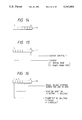
- FIG. 7 shows a portion of the stepping motor which is stopped in second phase excitation
- FIG. 8 shows a portion of the stepping motor which is stopped in first phase excitation
- FIG. 9 is a block diagram showing a schematic construction of a motor control circuit according to an embodiment of the present invention.
- FIG. 10 is a block diagram showing a schematic construction of a reading portion of a facsimile system having the motor control circuit of FIG. 9;
- FIG. 11 is a block diagram showing a schematic construction of a recording portion of the facsimile system having the motor control circuit of FIG. 9;
- FIG. 12 is a block diagram showing a schematic construction of the facsimile system
- FIG. 13 is a flow chart showing a process for setting an initial mode regarding the motor control circuit of FIG. 9;
- FIGS. 14 to 16 show data constructions of respective registers in the motor control circuit of FIG. 9;
- FIG. 17 is a flow chart showing a trigger output process regarding the motor control circuit of FIG. 9;
- FIG. 18 is a timing chart showing an operation of the motor control circuit of FIG. 9;
- FIG. 19 is a graph showing a displacement amount of the motor in the respective phase excitations effected by the motor control circuit of FIG. 9;
- FIG. 20 is a timing chart showing current values of the respective windings of the motor control circuit of FIG. 9;
- FIGS. 21A to 21C show motor driving currents of the respective windings of the motor control circuit of FIG. 9;
- FIG. 22 is a graph showing a relation between a motor torque and a motor speed under current control and non-current control.
- FIG. 23 is a flow chart showing manuscript feed control according to another embodiment of the present invention.
- FIG. 9 shows a schematic construction of a motor controlling portion in a sheet feeding apparatus according to the present invention.
- the motor controlling portion comprises a register 10 for storing a frequency dividing ratio in a counter 13, a register 11 for storing data of the presence of current control and presence of power down (i.e., normal mode or power down mode) of a driving current of a motor, and a register 12 for storing an exciting output, rotation direction and serial driving stepping number per one trigger, regarding the motor.
- the counter 13 executes the frequency dividing of the inputted block signal 14 as indicated by the register 10, and the frequency divided clock signal acts as a driving clock signal for the motor.
- a counter driver 15 controls the driving of a counter 17 and receives a frequency dividing clock signal 19 from the counter, a trigger signal 16 and a busy signal 18 from the counter 17.
- the counter driver circuit 15 receives the trigger signal 16 when the counter 17 is not being driven, it outputs a trigger signal 20 to the counter 17.
- the counter 17 begins to operate when it receives the trigger signal 20, and sends, to an exciting output circuit 21, pulses by the stepping number indicated by the register 12.
- the exciting output circuit 21 outputs exciting signals 22 ⁇ 24 on the basis of conditions of the register 12 and of the counter 17, thereby driving a motor driving circuit 25.
- the motor driving circuit 25 receives the exciting signals 22 ⁇ 24.
- the received exciting signals are decoded by a decoder 25-1 and are output from the circuit 25 as four phase motor exciting signals A, B, AX and BX.
- a power down indicating circuit 26 outputs a power down signal 33 when an indicating signal 27 from the register 11 indicates the presence of the current control and the motor current is set to the normal mode.
- the trigger signal 16 instructs the initiation of operation of the motor.
- the reference numeral 28 designates a latch signal for latching data 30 representing the frequency dividing ratio in the register 10
- 29 designates a latch signal for latching data 30 representing the serial driving stepping number and rotation direction of the motor in the register 12
- 31 designates a clear signal for clearing the registers 10 ⁇ 12
- 32 designates a latch signal for latching information such as the power down mode and the like in the register 11.
- the power down signal 33 is outputted when the motor is to be driven in the power down mode (where the current values of the windings of the motor is decreased by 50% or more, or less of those in the normal mode).
- the reference numeral 34 designates a busy signal showing a condition that the motor is being rotated.
- FIG. 10 is a block diagram showing a schematic construction of a reading portion or reader 404 (FIG. 12) in the facsimile system.
- the reader comprises a reading motor control circuit 40 including the circuits and the like shown in FIG. 9, a four phase unipolar stepping motor for feeding an original to be read, and a motor driving circuit 45 which receives an exciting signal 35 for each phase and other various signals from the reading motor control circuit 40 and drives the stepping motor with chopper drive.
- the motor driving circuit 45 can also drive the stepping motor with the current value (flowing in the windings of the stepping motor 41) of, for example, 1/2 of the current value in the normal mode.
- the reader further includes a stabilizer 42 for suppressing variation of luminance of a light 43 illuminating the original to stabilize the luminance of the light 43, and an image sensor 44 for reading the original image and for photoelectrically converting it.
- FIG. 11 is a block diagram showing a schematic construction of a recording portion or recorder 405 (FIG. 12) for recording the image on the recording sheet.
- the recorder comprises a recording motor control circuit 46 which controls the operation of a motor 47 for feeding the recording sheet and which has similar elements shown in FIG. 9, a motor driving circuit 45 having the same construction of the motor driving circuit of FIG. 10, a four phase unipolar stepping motor 47 for feeding the recording sheet, a thermal head 49 comprising a thermal line head for recording the image on the recording sheet on the basis of image information, and a head driver 48 for driving the thermal head 49.
- FIG. 12 is a block diagram showing a schematic construction of a facsimile system according to an embodiment of the present invention.
- the facsimile system comprises a modem 400, a line control unit (NCU) 401, a modem control circuit 402 for controlling the modem 400, a telephone 403, the reader 404 shown in FIG. 10, the recorder 405 shown in FIG. 11, sensor and the like 406 for detecting the presence of the recording sheet and of the original, a width of the recording sheet and the like, a speaker 407 for generating an error sound, monitor sound of the line and the like, an operation panel 408 including operation keys, displayers and the like, a ROM 409 for storing a control program of the CPU 411 and various data, a RAM 410 which is used as a work area of the CPU 411 and which can temporarily store the original image data, received image data and the like, and the above-mentioned CPU 411 including, for example, a microcomputer, various control circuits and the like for controlling the whole system.
- NCU line control unit
- modem control circuit 402 for controlling the modem 400
- a telephone 403 the reader 404
- FIG. 13 is a flow chart showing an initial setting process for the motor control circuit 40 or 46 shown in FIG. 9 or FIG. 10. A program for executing this process is stored in the ROM 409.
- step S1 the data for setting the motor driving frequency is written in the register 10 in a step Sl. In this way, the frequency dividing ratio of the clock signal 14 effected in the counter 13 is determined.
- step S2 information regarding the presense of the current control, the presence of the power down of the driving current of the motor and the like are set in the register 11.
- step S3 the information regarding the stepping number of the motor enable or disenable of the exciting output, normal or reverse of the rotation direction of the motor are set in the register 12.
- the latchings or settings of the various data in these registers can be effected by outputting the data corresponding to the data bath 30 and by latching the data in the desired registers by means of the corresponding latch signal.
- FIG. 14 shows a data construction of the register 10, where the information for setting or determining the motor driving frequency (frequency dividing ratio) is stored.
- FIG. 15 shows a data construction of the register 11, which indicates that, when MSB is "0", the current of the motor flows in the normal mode and, when the MSB is "1", the current of the motor flows in the power down mode, and that, when LSB is "1", the current control is indicated or instructed.
- FIG. 16 shows a data construction of the register 12, which indicates that, when the MSB is "1", the exciting output is enable and, when the MSB is "0", the exciting output is disenable and that, when a sixth bit is "1", the rotation direction of the motor is normal and, and the sixth bit is "0" the rotation direction of the motor is reverse.
- Bits 0 ⁇ 5 indicate the stepping number of the motor serially rotated by a single trigger output.
- FIG. 17 is a flow chart showing outputting operation of the trigger signal 16 outputted to the respective motor control circuits of the reader 404 and the recorder 405 of the CPU 411.
- the busy signal 34 from each motor control circuit is inputted, and the motor driving trigger signal 16 is outputted when the corresponding motor is not driven.
- FIG. 18 is a timing chart showing an example of the current control in the motor control circuit 40 or 46 of the facsimile system according to the embodiment of the present invention.
- the register 10 is set to "5"
- the register 11 is set to "1”
- the register 12 is set to "C7H" (H shows a six-decimal number).
- the clock signal 19 is a signal obtained by frequency-dividing the clock signal 14 into five by means of the counter 13 in correspondence to the value "5" of the register 10.
- the reference numeral 500 designates a condition that the excitation becomes enable by setting the value "C7H” in the register 12. Since the LSB of the register 11 is "1", the current control is in a high level ("1").
- the reference numeral 501 shows an inputted timing of the trigger signal 16, from where the motor drive is started.
- A, AX, B and BX show exciting signals of the four phase motor.
- the power down signal 33 becomes the high level, thus reducing the value of the current flowing the windings of the motor to about 1/2.
- the values of the current flowing the windings of the motor will be substantially the same.
- This power down signal 33 is output from the aforementioned power down indicating circuit 26, which circuit receives a value LSB (DA) of the inputting signal of the decoders 25-1 and controls to output the power down signal 33 when this value is "1" (high level).
- LSB LSB
- FIG. 19 shows a relation between the excitation condition of the motor and the displacement amount of the motor corresponding thereto, when the above current control is executed. As seen in FIG. 19, the motor is driven to have the same displacement amounts in both first and second phase excitations.
- FIG. 20 is a timing chart showing the current values flowing in the windings of the motor, where iA, iAX, iB and iBX show the current value flowing the respective windings.
- iA, iAX, iB and iBX show the current value flowing the respective windings.
- FIG. 22 shows a relation between the torque and the speed of the stepping motor
- FIG. 23 shows a flow chart for a motor controlling process in the original reading operation in a facsimile system according to another embodiment of the present invention.
- a stepping motor used as the aforementioned reading motor has a pull-in torque which decreases as the driving frequency thereof increases.
- a ratio of such reduction in the pull-in torque when the current flowing the windings of the stepping motor is controlled differs from that when the current is controlled. More particularly, the torque when the current is controlled will more decrease than that when the current control is not effected.
- the motor when the original image to be transmitted is read, the motor is being rotated at a low speed in consideration of the sensitivity of the photoelectric converter element (image sensor), the transmitting speed and the like.
- the motor is rotated at a higher speed to shorten the working time.
- the original reading control sequence shown in the flow chart of FIG. 23 can meet with such requirements.
- a step S10 the rotation speed of the original feeding motor is set to 800 pps, and in a step Sll non-current control mode is set. Then, in steps S12 ⁇ S15, the original is fed to the reading position at a speed of 800 pps, and in a step S16 the rotation speed of the motor is decreased to 400 pps immediately before the reading of the original is initiated. Then, in a step S17, the current control mode is set, thus performing the reading operation of the original to be transmitted, while executing above-mentioned current control at a low speed (steps S18 ⁇ S20).
- step S21 the rotation speed of the motor is returned to 800 pps again when the reading operation of the original is completed, and in a step S22 the current control is inhibited, thus ejecting the original at a higher speed (steps S23 ⁇ S25).
- this sequence can be applied to the recording sheet feeding motor in the recoder in the same manner.
- the motor can be rotated at a low speed while exciting the current control, for example when the image is being recorded on the recording sheet through the thermal head, and can be rotated at a higher speed without the current control to feed the recording sheet at a high speed, when the recording sheet is fed to the recording position and/or when the recorded sheet is ejected.
- an example of the PM-type stepping motor is used.
- a stepping motor in which a distance between magnetics arranged on a stator and rotor thereof can be changed in accordance with the change in the excited phases is used for reading the original, recording the image and cutting the recording sheet, by changing the current flowing in the windings of the motor in accordance with the change in the excited phases, the holding torque of the motor can be kept constant.
- the stepping motor by controlling the value of the current flowing in the windings of the stepping motor in correspondence to the conditions of the phase excitation of the motor, the stepping motor can be smoothly and uniformly rotated whereby the recording sheet and the original can be fed at a constant or even speed.
- the reading of the original and the recording of the image to be reproduced can be performed with high quality.
- the cutting noise of the recording sheet can be reduced.
- the damping amount of the motor is reduced, the noise in the whole sheet feeding apparatus can also be reduced.
- the current control is not executed when the sheet is to be fed at a high speed, but is executed when the sheet is to be fed at a low speed, the feeding error of the sheet can be eliminated and the working speed of the whole apparatus can be increased.
- the vibration of the stepping motor can be reduced.
- the reading of the original and the recording of the image to be reproduced can be performed with high quality.
- the cutting noise generated in the sheet cutting operation can be reduced.
Landscapes
- Engineering & Computer Science (AREA)
- Multimedia (AREA)
- Signal Processing (AREA)
- Control Of Stepping Motors (AREA)
- Delivering By Means Of Belts And Rollers (AREA)
- Facsimile Scanning Arrangements (AREA)
Applications Claiming Priority (2)
| Application Number | Priority Date | Filing Date | Title |
|---|---|---|---|
| JP63118269A JP2693483B2 (ja) | 1988-05-17 | 1988-05-17 | シート搬送装置及びその装置を備えたフアクシミリ装置 |
| JP63-118269 | 1988-05-17 |
Publications (1)
| Publication Number | Publication Date |
|---|---|
| US5062006A true US5062006A (en) | 1991-10-29 |
Family
ID=14732458
Family Applications (1)
| Application Number | Title | Priority Date | Filing Date |
|---|---|---|---|
| US07/352,188 Expired - Lifetime US5062006A (en) | 1988-05-17 | 1989-05-15 | Sheet feeding apparatus and facsimile system having same |
Country Status (2)
| Country | Link |
|---|---|
| US (1) | US5062006A (ja) |
| JP (1) | JP2693483B2 (ja) |
Cited By (10)
| Publication number | Priority date | Publication date | Assignee | Title |
|---|---|---|---|---|
| US5164845A (en) * | 1988-10-14 | 1992-11-17 | Canon Kabushiki Kaisha | Image reading apparatus |
| US5198741A (en) * | 1989-07-31 | 1993-03-30 | Canon Kabushiki Kaisha | Drive control system of stepping motor |
| US5198909A (en) * | 1989-05-12 | 1993-03-30 | Fuji Xerox Co., Ltd. | Driving apparatus and method for scanning system for use in image recording apparatus |
| US5239393A (en) * | 1988-10-14 | 1993-08-24 | Canon Kabushiki Kaisha | Image reading apparatus |
| US5260811A (en) * | 1989-08-18 | 1993-11-09 | Minolta Camera Kabushiki Kaisha | Image scanning apparatus having motor operating under improved drive control |
| US5963341A (en) * | 1996-06-29 | 1999-10-05 | Samsung Electronics Co., Ltd. | Device for changing resolution of facsimile |
| US6144184A (en) * | 1997-08-09 | 2000-11-07 | Brother Kogyo Kabushiki Kaisha | Motor controlling method and apparatus |
| US20030141838A1 (en) * | 2002-01-23 | 2003-07-31 | Samsung Electronics Co., Ltd | Method of driving step motor |
| US20050057209A1 (en) * | 2003-07-18 | 2005-03-17 | Toshiyuki Andoh | Method, apparatus, and program for driving a motor in a feedback control system, capable of suppressing motor oscillation |
| US20050083007A1 (en) * | 2003-09-17 | 2005-04-21 | Takao Nireki | Motor stop control device utilizable for gaming machine and gaming machine using the same |
Families Citing this family (1)
| Publication number | Priority date | Publication date | Assignee | Title |
|---|---|---|---|---|
| JP4901783B2 (ja) * | 2008-02-21 | 2012-03-21 | 京楽産業.株式会社 | パチンコ遊技機 |
Citations (2)
| Publication number | Priority date | Publication date | Assignee | Title |
|---|---|---|---|---|
| US3622695A (en) * | 1968-10-07 | 1971-11-23 | Xerox Corp | Facsimile system having incremental stepping paper drive assembly |
| US4857817A (en) * | 1987-01-30 | 1989-08-15 | Canon Kabushiki Kaisha | Drive circuit for stepping motor |
Family Cites Families (3)
| Publication number | Priority date | Publication date | Assignee | Title |
|---|---|---|---|---|
| JPS5869499A (ja) * | 1981-10-20 | 1983-04-25 | Fuji Xerox Co Ltd | ステツプモ−タ励磁方式 |
| JPS6035998A (ja) * | 1983-08-04 | 1985-02-23 | Ricoh Co Ltd | パルスモ−タ駆動方式 |
| JPS6240098A (ja) * | 1985-08-14 | 1987-02-21 | Fujitsu Ltd | パルスモ−タ制御方式 |
-
1988
- 1988-05-17 JP JP63118269A patent/JP2693483B2/ja not_active Expired - Lifetime
-
1989
- 1989-05-15 US US07/352,188 patent/US5062006A/en not_active Expired - Lifetime
Patent Citations (2)
| Publication number | Priority date | Publication date | Assignee | Title |
|---|---|---|---|---|
| US3622695A (en) * | 1968-10-07 | 1971-11-23 | Xerox Corp | Facsimile system having incremental stepping paper drive assembly |
| US4857817A (en) * | 1987-01-30 | 1989-08-15 | Canon Kabushiki Kaisha | Drive circuit for stepping motor |
Cited By (17)
| Publication number | Priority date | Publication date | Assignee | Title |
|---|---|---|---|---|
| US5164845A (en) * | 1988-10-14 | 1992-11-17 | Canon Kabushiki Kaisha | Image reading apparatus |
| US5239393A (en) * | 1988-10-14 | 1993-08-24 | Canon Kabushiki Kaisha | Image reading apparatus |
| US5198909A (en) * | 1989-05-12 | 1993-03-30 | Fuji Xerox Co., Ltd. | Driving apparatus and method for scanning system for use in image recording apparatus |
| US5198741A (en) * | 1989-07-31 | 1993-03-30 | Canon Kabushiki Kaisha | Drive control system of stepping motor |
| US5260811A (en) * | 1989-08-18 | 1993-11-09 | Minolta Camera Kabushiki Kaisha | Image scanning apparatus having motor operating under improved drive control |
| US5963341A (en) * | 1996-06-29 | 1999-10-05 | Samsung Electronics Co., Ltd. | Device for changing resolution of facsimile |
| CN1105448C (zh) * | 1996-06-29 | 2003-04-09 | 三星电子株式会社 | 用于改变传真机的分辨率的装置 |
| US6144184A (en) * | 1997-08-09 | 2000-11-07 | Brother Kogyo Kabushiki Kaisha | Motor controlling method and apparatus |
| US20030141838A1 (en) * | 2002-01-23 | 2003-07-31 | Samsung Electronics Co., Ltd | Method of driving step motor |
| US6984956B2 (en) * | 2002-01-23 | 2006-01-10 | Samsung Electronics Co., Ltd. | Method of driving step motor |
| US20050057209A1 (en) * | 2003-07-18 | 2005-03-17 | Toshiyuki Andoh | Method, apparatus, and program for driving a motor in a feedback control system, capable of suppressing motor oscillation |
| EP1521133A1 (en) * | 2003-07-18 | 2005-04-06 | Ricoh Company, Ltd. | Method, apparatus, and program for driving a stepping motor in an image forming apparatus, to suppress oscillations from feedback control |
| US20070189815A1 (en) * | 2003-07-18 | 2007-08-16 | Toshiyuki Andoh | Method,apparatus, and program for driving a motor in a feedback control system, capable of suppressing motor oscillation |
| US7330009B2 (en) | 2003-07-18 | 2008-02-12 | Ricoh Co., Ltd. | Method, apparatus, and program for driving a motor in a feedback control system, capable of suppressing motor oscillation |
| US7800335B2 (en) | 2003-07-18 | 2010-09-21 | Ricoh Company, Ltd. | Method, apparatus, and program for driving a motor in a feedback control system, capable of suppressing motor oscillation |
| US20050083007A1 (en) * | 2003-09-17 | 2005-04-21 | Takao Nireki | Motor stop control device utilizable for gaming machine and gaming machine using the same |
| US7199546B2 (en) * | 2003-09-17 | 2007-04-03 | Aruze Corp. | Motor stop control device utilizable for gaming machine and gaming machine using the same |
Also Published As
| Publication number | Publication date |
|---|---|
| JP2693483B2 (ja) | 1997-12-24 |
| JPH01291697A (ja) | 1989-11-24 |
Similar Documents
| Publication | Publication Date | Title |
|---|---|---|
| US5062006A (en) | Sheet feeding apparatus and facsimile system having same | |
| US5001410A (en) | Driving system for stepping motor | |
| US5262801A (en) | Image recording apparatus | |
| US4983891A (en) | Motor driving apparatus with speed determined chopped drive and constant voltage drive control | |
| US5669721A (en) | Method and apparatus for achieving increased printer throughput | |
| JP2848652B2 (ja) | 画像形成装置 | |
| JPH06121592A (ja) | パルスモータの駆動方法 | |
| JP3173901B2 (ja) | 用紙搬送装置 | |
| JP3101079B2 (ja) | ファクシミリ装置 | |
| JP3350089B2 (ja) | ファクシミリ装置 | |
| JP3031063B2 (ja) | 印字装置 | |
| JPH1169889A (ja) | 紙送り用ステッピングモータの制御方法及び紙送り装置 | |
| JP3716594B2 (ja) | 画像読取装置 | |
| JPH0217895A (ja) | ステツピングモータの駆動方式 | |
| JP3733267B2 (ja) | ステップモータ駆動制御回路 | |
| JP3428268B2 (ja) | ステッパーモータの制御方法 | |
| JPS61294964A (ja) | ステツピングモ−タ駆動回路 | |
| JPS6355831B2 (ja) | ||
| JP2853519B2 (ja) | ファクシミリ装置 | |
| JP3050270B2 (ja) | シリアルプリンタ | |
| JPH0965695A (ja) | ステッピングモータ駆動制御装置 | |
| JP2002204339A (ja) | 画像通信装置 | |
| JP2000175496A (ja) | ステップモータ駆動装置 | |
| JPH1169885A (ja) | 紙送り用ステッピングモータの制御方法及び紙送り装置 | |
| JP2693437C (ja) |
Legal Events
| Date | Code | Title | Description |
|---|---|---|---|
| AS | Assignment |
Owner name: CANON KABUSHIKI KAISHA, A CORP. OF JAPAN, JAPAN Free format text: ASSIGNMENT OF ASSIGNORS INTEREST.;ASSIGNOR:MIURA, SHIGEO;REEL/FRAME:005078/0769 Effective date: 19890511 |
|
| STCF | Information on status: patent grant |
Free format text: PATENTED CASE |
|
| CC | Certificate of correction | ||
| FEPP | Fee payment procedure |
Free format text: PAYOR NUMBER ASSIGNED (ORIGINAL EVENT CODE: ASPN); ENTITY STATUS OF PATENT OWNER: LARGE ENTITY |
|
| FPAY | Fee payment |
Year of fee payment: 4 |
|
| FEPP | Fee payment procedure |
Free format text: PAYER NUMBER DE-ASSIGNED (ORIGINAL EVENT CODE: RMPN); ENTITY STATUS OF PATENT OWNER: LARGE ENTITY |
|
| FPAY | Fee payment |
Year of fee payment: 8 |
|
| FPAY | Fee payment |
Year of fee payment: 12 |