US5085182A - Variable valve timing rocker arm arrangement for internal combustion engine - Google Patents
Variable valve timing rocker arm arrangement for internal combustion engine Download PDFInfo
- Publication number
- US5085182A US5085182A US07/587,939 US58793990A US5085182A US 5085182 A US5085182 A US 5085182A US 58793990 A US58793990 A US 58793990A US 5085182 A US5085182 A US 5085182A
- Authority
- US
- United States
- Prior art keywords
- rocker arm
- rocker
- cam
- bore
- plunger
- Prior art date
- Legal status (The legal status is an assumption and is not a legal conclusion. Google has not performed a legal analysis and makes no representation as to the accuracy of the status listed.)
- Expired - Lifetime
Links
Images




Classifications
-
- F—MECHANICAL ENGINEERING; LIGHTING; HEATING; WEAPONS; BLASTING
- F01—MACHINES OR ENGINES IN GENERAL; ENGINE PLANTS IN GENERAL; STEAM ENGINES
- F01L—CYCLICALLY OPERATING VALVES FOR MACHINES OR ENGINES
- F01L1/00—Valve-gear or valve arrangements, e.g. lift-valve gear
- F01L1/26—Valve-gear or valve arrangements, e.g. lift-valve gear characterised by the provision of two or more valves operated simultaneously by same transmitting-gear; peculiar to machines or engines with more than two lift-valves per cylinder
- F01L1/267—Valve-gear or valve arrangements, e.g. lift-valve gear characterised by the provision of two or more valves operated simultaneously by same transmitting-gear; peculiar to machines or engines with more than two lift-valves per cylinder with means for varying the timing or the lift of the valves
-
- F—MECHANICAL ENGINEERING; LIGHTING; HEATING; WEAPONS; BLASTING
- F01—MACHINES OR ENGINES IN GENERAL; ENGINE PLANTS IN GENERAL; STEAM ENGINES
- F01L—CYCLICALLY OPERATING VALVES FOR MACHINES OR ENGINES
- F01L1/00—Valve-gear or valve arrangements, e.g. lift-valve gear
- F01L1/12—Transmitting gear between valve drive and valve
- F01L1/18—Rocking arms or levers
- F01L1/185—Overhead end-pivot rocking arms
Definitions
- the present invention relates generally to a variable valve timing arrangement for an internal combustion engine and more specifically to a rocker arm construction for such an arrangement.
- JP-A-63-167016 and JP-A-63-57805 disclosed rocker arm arrangements which include a first rocker arm which is arranged to cooperate with a low speed cam and a second rocker arm which cooperates with a high speed cam.
- the two rocker arms pivotally mounted on a common rocker arm shaft.
- a hydraulically operated connection device which enables the first and second rocker arms to be selectively locked together, comprises a set of plunger bores which are formed in the rocker arms in a manner to be parallel with and at a predetermined distance from the axis of the shaft about which the arms are commonly pivotal.
- a main rocker arm which is pivotally mounted on a rocker shaft has one or more sub-rocker arms pivotally mounted thereon.
- the main rocker arm is arranged to synchronously open and close two poppet valves.
- Each of the sub-rocker arms can be selectively locked to the main one by way of hydraulically operated plunger arrangements.
- the main rocker arm is provided with a roller type cam follower which follows a low speed cam.
- the sub-rocker arms are provided with followers which engage high or very high speed cams. Lost motion springs which maintain the sub-rocker arms in contact with the cams are mounted on the main rocker arm.
- a first aspect of the present invention comes in an internal combustion engine having a cylinder head and a poppet valve which is associated with the cylinder head and a rocker shaft and which features: a first rocker arm, the first rocker arm being pivotally mounted on the rocker shaft, arranged to engage a stem of the poppet valve and to engage a first cam having a profile suited for low speed engine operation; a second rocker arm, the second rocker arm being pivotally mounted on the first rocker arm arranged to engage a second cam having a profile suited for high speed engine operation; hydraulically operated engagement means for selectively connecting the first and second rocker arms in a manner wherein relative movement therebetween is prevented; and a lost motion spring mounted on the first rocker arm and arranged to engage the second rocker arm in a manner which biases the second rocker arm against the second cam.
- a second aspect of the present invention comes in a valve train for an internal combustion engine which features: a first rocker arm, the first rocker arm being motivated by a first cam having a profile suited for low speed engine operation, the first rocker arm being pivotally mounted on a rocker shaft; a second rocker arm, the second rocker arm being arranged to be motivated by a second cam having a profile suited for high speed engine operation, the second rocker shaft being pivotally mounted on the first rocker arm; a third rocker arm, the second rocker arm being arranged to be motivated by a third cam having a profile suited for high speed engine operation, the third rocker shaft being pivotally mounted on the first rocker arm; a first hydraulically operated interlocking device which selectively interconnects the first and second rocker arms in a manner wherein relative movement therebetween is prevented; a second hydraulically operated interlocking device which selectively interconnects the first and third rocker arms in a manner wherein relative movement therebetween is prevented; a first lost motion spring mounted on the first rocker
- FIG. 1 is a plan view of a rocker arm arrangement according to a first embodiment of the present invention
- FIG. 2 is a side sectional view as taken along line X--X of FIG. 1;
- FIG. 3 is a side sectional view as taken along line Z--Z of FIG. 1;
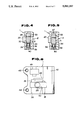
- FIGS. 4 and 5 are sectional views as taken along section line Y--Y of FIG. 1 showing the interlocking arrangement which interconnects the high and low speed rocker arms condition for low and high speed operation, respectively;
- FIG. 6 is a plan view showing the main rocker arm of the first embodiment
- FIG. 7 is a graph showing in terms of engine speed and engine torque, the characteristics which are provided with the first embodiment of the present invention.
- FIG. 8 is a plan view showing a second embodiment of the present invention.
- FIG. 9 is a sectional view as taken along section line X--X of FIG. 8;
- FIG. 10 is a plan view showing the main rocker arm used in the second embodiment
- FIG. 11 is a graph which shows in terms of engine speed and engine torque, the engine operational characteristics which are provided by the second embodiment at low, high and very high engine speeds, respectively;
- FIG. 12 is a graph which shows in terms of engine speed and engine torque the engine operational characteristics which can be provided during idling, low speed/high load and high speed/high load modes of engine operation by the second embodiment of the present invention
- FIG. 13 is plan view of a third embodiment of the present invention.
- FIG. 14 is a sectional view as taken along section line X--X of FIG. 13;
- FIG. 15 is a graph showing the engine torque generation characteristics achieved with the third embodiment.
- FIGS. 1-6 show a first embodiment of the present invention.
- This embodiment takes the form of a rocker arm which is arranged to synchronously open and close two poppet valve 9.
- These valves 9 may be either inlet or exhaust valves.
- a main rocker arm 1 is arranged so that one end there of engages both of the valves while the other is pivotally supported on the cylinder head by way of main rocker shaft 3.
- the ends of the main rocker arm which engages the valves are provided with adjust screws and locknuts 11.
- a roller 14 is rotatably mounted on the main rocker arm 1 by way of needle bearings 12. This roller is arranged to act as a follower which engages a low speed cam 21 (viz., a cam which is configured for low speed engine operation).
- the main rocker arm 1 has an essentially rectangular shape.
- a sub-rocker arm 2 is pivotally supported on the main rocker arm 1 by way of a sub-rocker arm shaft 16.
- the shaft 16 is received in a bore 17 formed in the sub-rocker arm 2 and a coaxial bore 18 formed in the main rocker arm 1.
- the sub-rocker arm 2 does not directly engage the valves 9 and is formed with a convexly shaped cam follower portion 23 which is arranged to engage a high speed cam 22.
- a lost motion spring 25 is received in a blind bore or recess 26 formed in the main rocker arm 1.
- the lost motion spring 25 is a coil spring.
- the lower end of the spring engages the blind end wall of the bore 26 while a retainer 27, which is reciprocatively disposed in the upper end of the bore 26, encloses the upper end of the same.
- a follower 28 is formed on the underside of the sub-rocker arm 2 and arranged to engage the top of the retainer 27.
- An interlocking arrangement for selectively interconnecting the main and sub-rocker arms 1, 2 comprises a structure of the nature shown in FIGS. 4 and 5.
- this structure includes a plunger 31 which is reciprocatively received in a though bore 32 formed in the sub-rocker arm 2, and plungers 33, 34 which are respectively received in bores 35, 36 formed in the main rocker arm 1.
- the plunger 33 defines a variable volume hydraulic fluid chamber 37 in the bore 35.
- a return spring 38 is disposed in the bore 36 between the plunger 34 and a plug 39 in which an air vent bore 40 is formed.
- the plungers 31, 33 and 34 assume the positions shown in FIG. 4.
- the plunger 33 and the bore are dimensioned so that when the hydraulic pressure is below the above mentioned level, the end face which engages one of the end faces of the plunger 31, lies flush with the wall surface of the main rocker arm 1 in which the bore 33 is formed.
- the plunger 31 is dimensioned so that under these conditions its end faces lie flush with the side walls of the sub-rocker arm 2. This of course maintains the plunger 34 in a state wherein its end face lies flush with the wall surface of the main rocker arm in which the bore 36 is formed.
- sub-rocker arm 2 is rendered pivotal with respect to the main rocker arm 1 and thus can be driven down against the bias of the lost motion spring 25 under the influence of the high speed cam 22 engaging the cam follower 23.
- a hydraulic passage structure generally denoted by the numeral 41 in FIG. 1 provides fluid communication between the hydraulic chamber 37 and a non-illustrated control source.
- this passage structure comprises: a passage 43 formed in the main rocker arm which leads from one end of the bore in which the hydraulic chamber 37 is defined to a horizontally large diameter bore 42 in which the rocker shaft 3 is disposed; an axial bore which defines an oil gallery 44 in the rocker shaft 3; an annular recess formed about the rocker shaft 3; and a radial bore 46 which provides fluid communication between the oil gallery 44 and the recess 47.
- Passage 43 communicates with the recess 47.
- a plug 45 closes the drill hole produced when the passage 43 is formed in the main rocker arm.
- FIG. 6 shows the structure of the main rocker arm.
- 48 denote the threaded bores in which the adjust screws 10 are received
- 49 denotes the recess in which the roller 14 is disposed
- 50 denotes the opening in which the sub-rocker arm 2 is received.
- the above mentioned control source comprises a switching valve (not shown) which is fluidly interposed between the chamber 37 and an oil pump.
- the valve is controlled by a control unit which receives data inputs indicative of engine speed, coolant temperature, lubricant oil temperature, supercharge pressure, engine throttle valve position. This control unit determines when it is necessary to switch between high and low cam lifting.
- the low and high speed cams 21, 22 are both formed integrally on a cam shaft and have profiles which are designed to produce the appropriate amount of lift and timing for low and high engine speed operation, respectively. Viz., the amount of lift and/or the length of time the valve is opened by the high speed cam 22 is greater than that induced the low speed one.
- the sub-rocker arm 2 (high speed rocker arm) is pivotally supported on the main rocker arm 1 (low speed rocker arm) per se by way of the sub-rocker shaft 16 it is possible to greatly reduce the size and mass of the same.
- the mass of the sub-rocker arm is lower than that of the prior art discussed in the opening paragraphs of the instant disclosure. This enables the mass of the valve train to be reduced. Further, during high speed modes of operation when the two rocker arms are locked together so as to move as a single unit, as the mass of each unit is reduced as compared with said prior art the valve following characteristics are improved.
- the lost motion spring can be relatively small and weak. This reduces the amount of friction which is produced between the high speed cam 22 and the follower 23 and thus reduces engine fuel consumption.
- sub-rocker arm 2 is pivotally mounted on the main rocker arm 1 by way of sub-rocker shaft 16, it is possible to assembly the both to form a unit which can be then mounted on the rocker shaft.
- the precision with which the roller 14 and follower 23 are mounted on the respective rocker arms can be checked before the unit is actually mounted on the cylinder head. This reduces the amount of work which must be done in order to ensure uniform lift characteristics from cylinder to cylinder. That is to say, with the above mentioned prior art, these factors cannot be checked until both rocker arms are mounted on the cylinder head.
- the lost motion spring 25 does not require a seat to be formed on the cylinder head per se, reduces the amount of variation during assembly.
- the plungers 31, 33 and 34 and the return spring can be assembled as a unit, the amount of time required for assembling valve train on the cylinder head is reduced.
- FIGS. 8 and 9 show a second embodiment of the present invention.
- three cams are provided on the cam shaft.
- the rocker arm arrangement comprises a main rocker arm 1 on which a first cam follower (roller) 14 is mounted; and first and second sub-rocker arms 54, 55 which are arranged to cooperate with the second and third cams 52, 53, respectively.
- the sub-rocker arms 54, 55 are pivotally mounted on the main rocker arm 1 by way of a common sub-rocker shaft 56.
- Plungers 57, 58 and 59 and a return spring 60 are arranged to provide selective interlocking between the main and first sub-rocker arms 1, 54.
- the movement of the plungers is controlled by hydraulic pressure which is supplied through a control passage 61.
- Plungers 62, 63 and 64 and a return spring 65 are arranged to provide selective interlocking between the main and second sub-rocker arms 1, 55.
- the movement of these plungers is controlled by hydraulic pressure which is supplied through a control passage 66.
- the second sub-rocker arm 55 cooperates with a lost motion spring arrangement comprised of a spring 67, a retainer 68, and a stopper 69.
- a lost motion spring arrangement comprised of a spring 67, a retainer 68, and a stopper 69.
- the bore in which the spring and the retainer are disposed is not blind and the stopper 69 is provided close one end of said bore.
- the first rocker arm is arranged to cooperate with a similar non-illustrated lost motion spring arrangement.
- the main rocker arm 1 is provided with hydraulic lash adjusters 71 which engage the tops of the valves 9. These devices are supplied with hydraulic fluid under pressure by way of passages 72, 74 as shown in FIG. 10.
- numerals 75 and 76 generally denote the bores in which the plungers 62, 63 and 74 and 57, 58 and 59 are disposed.
- the passage 72 is shown as passing below the bores 75 and 76; that 49 denotes the opening in which the roller 14 is disposed; 77 is the opening in which the first sub-rocker arm 54 is disposed; 78 is the bore in which the first lost motion spring arrangement is received; 79 is the opening in which the second rocker arm 55 is received; and 80 is the bore in which the second lost motion spring arrangement is disposed.
- Passages 61, 66 and 72 are arranged to communicate with oil galleries 61', 66' and 72' which are formed in the rocker shaft 3.
- This arrangement is such that the cams 51, 52 and 53 are used during low, high and very high engine speed operations, respectively. By appropriately configuring these cams, it is possible to achieve the torque output characteristics shown in FIG. 11.
- the first cam 51 configuring the first cam 51 to provide a small low lift over a small crankangle range, it is possible to improve combustion characteristics during idling; and by configuring the cam 52 to provide appropriate lift for low speed/high load and cam 53 to provide the appropriate lift for high speed high load, the power output characteristics shown in FIG. 12 are rendered possible.
- FIGS. 13 and 14 show a third embodiment of the present invention.
- This embodiment is essentially similar to the second one and differs in that four cams and three sub-rocker arms are utilized.
- cams 81, 82, 83 and 84 are provided on the cam shaft.
- the first cam 81 cooperates with the roller 14 of the main rocker arm 1, while cams 82-84 cooperate with the three sub-rocker arms 85, 86 and 87.
- Cam 81 is configured for low speed engine operation while cams 82-84 are configured from sequentially increasing high speed operational modes.
- the three sub-rocker arms are respectively interlocked with the main rocker arm 1 by way of plunger sets 89, 90 and 91. Each of these are offset with respect to one another in essentially the same manner as the plunger sets of the second embodiment are.
- the plunger sets 89, 90 and 91 are supplied with control pressures via passage 92, 93 and 94 (formed in the rocker shaft).
- Passage 72' supplies hydraulic pressure to the hydraulic lash adjusters 61.
- the three sub-rocker arms cooperate with lost motion spring arrangements.
- FIG. 14 the lost motion spring arrangement which cooperates with sub-rocker arm 87 is shown. This arrangement comprises a spring 95, a retainer 96 and a stopper 97.
Landscapes
- Engineering & Computer Science (AREA)
- Mechanical Engineering (AREA)
- General Engineering & Computer Science (AREA)
- Valve Device For Special Equipments (AREA)
Applications Claiming Priority (2)
| Application Number | Priority Date | Filing Date | Title |
|---|---|---|---|
| JP1-248677 | 1989-09-25 | ||
| JP1248677A JP2810442B2 (ja) | 1989-09-25 | 1989-09-25 | エンジンの弁作動装置 |
Publications (1)
| Publication Number | Publication Date |
|---|---|
| US5085182A true US5085182A (en) | 1992-02-04 |
Family
ID=17181694
Family Applications (1)
| Application Number | Title | Priority Date | Filing Date |
|---|---|---|---|
| US07/587,939 Expired - Lifetime US5085182A (en) | 1989-09-25 | 1990-09-25 | Variable valve timing rocker arm arrangement for internal combustion engine |
Country Status (4)
| Country | Link |
|---|---|
| US (1) | US5085182A (fr) |
| EP (1) | EP0420159B1 (fr) |
| JP (1) | JP2810442B2 (fr) |
| DE (1) | DE69018747T2 (fr) |
Cited By (24)
| Publication number | Priority date | Publication date | Assignee | Title |
|---|---|---|---|---|
| US5183015A (en) * | 1991-04-26 | 1993-02-02 | Atsugi Unisia Corporation | Valve operating apparatus |
| US5203289A (en) * | 1990-09-21 | 1993-04-20 | Atsugi Unisia Corporation | Variable timing mechanism |
| US5239952A (en) * | 1991-11-08 | 1993-08-31 | Atsugi Unisia Corporation | Valve actuating apparatus |
| US5297516A (en) * | 1991-10-23 | 1994-03-29 | Atsugi Unisia Corporation | Valve actuating apparatus |
| US5301636A (en) * | 1992-09-17 | 1994-04-12 | Nissan Motor Co., Ltd. | Valve operating mechanism of internal combustion engine |
| US5388552A (en) * | 1992-09-16 | 1995-02-14 | Honda Giken Kogyo Kabushiki Kaisha | Valve operating device for an internal combustion engine |
| US5456225A (en) * | 1993-08-18 | 1995-10-10 | Honda Giken Kogyo Kabushiki Kaisha | Valve operating device for internal combustion engine |
| US5590627A (en) * | 1996-01-02 | 1997-01-07 | Chrysler Corporation | Fluid inletting and support structure for a variable valve assembly |
| US5669342A (en) * | 1994-04-14 | 1997-09-23 | Ina Walzlager Schaeffler Kg | Device for simultaneous actuation of at least two gas exchange valves |
| US5701857A (en) * | 1995-10-12 | 1997-12-30 | Unisia Jecs Corporation | Cylinder valve operating system |
| US5794576A (en) * | 1996-02-20 | 1998-08-18 | Unisia Jecs Corporation | Engine cylinder valve controlling apparatus |
| US6032624A (en) * | 1997-05-19 | 2000-03-07 | Unisia Jecs Corporation | Engine valve actuating devices |
| EP1236870A2 (fr) | 2001-02-28 | 2002-09-04 | Unisia Jecs Corporation | Dispositif de commande variable de soupape de moteur à combustion interne |
| US20030075129A1 (en) * | 1999-07-01 | 2003-04-24 | Spath Mark J. | Valve lifter assembly for selectively deactivating a cylinder |
| US20030169925A1 (en) * | 2002-03-11 | 2003-09-11 | Jean-Pierre Polonowski | Character recognition system and method |
| US6640761B2 (en) * | 2000-04-28 | 2003-11-04 | Mahle Ventiltrieb Gmbh | Control device for an intake valve or exhaust valve of an internal combustion engine |
| US20030221645A1 (en) * | 2002-05-24 | 2003-12-04 | Shinichi Murata | Valve system for internal combustion engine |
| US6705259B1 (en) * | 2002-12-10 | 2004-03-16 | Delphi Technologies, Inc. | 3-step cam-profile-switching roller finger follower |
| US20050120989A1 (en) * | 2002-02-06 | 2005-06-09 | Norbert Geyer | Switch element for valve actuation in an internal combustion engine |
| US20090145389A1 (en) * | 2007-12-06 | 2009-06-11 | Hyundai Motor Company | Rocker arm for variable valve lift, and variable valve lift apparatus having the same |
| US20090159029A1 (en) * | 2007-11-21 | 2009-06-25 | Mario Kuhl | Switchable Tappet |
| US20110061615A1 (en) * | 2009-09-17 | 2011-03-17 | Hendriksma Nick J | Apparatus and Method for Setting Mechanical Lash in a Valve-Deactivating Hydraulic Lash Adjuster |
| CN103038459A (zh) * | 2010-06-02 | 2013-04-10 | 本田技研工业株式会社 | 用于内燃机的阀门控制设备 |
| USRE44864E1 (en) | 2001-09-19 | 2014-04-29 | Ina Schaeffler Kg | Switching element for a valve train of an internal combustion engine |
Families Citing this family (16)
| Publication number | Priority date | Publication date | Assignee | Title |
|---|---|---|---|---|
| JPH04127813U (ja) * | 1991-05-16 | 1992-11-20 | 日産自動車株式会社 | 内燃機関の動弁装置 |
| JPH0524904U (ja) * | 1991-06-26 | 1993-04-02 | 日産自動車株式会社 | エンジンの可変動弁装置 |
| JPH0585229A (ja) * | 1991-09-30 | 1993-04-06 | Nissan Motor Co Ltd | パワートレーンの総合制御装置 |
| DE4136143A1 (de) * | 1991-11-02 | 1993-05-06 | Audi Ag, 8070 Ingolstadt, De | Ventilsteuereinrichtung fuer eine brennkraftmaschine |
| AU657040B2 (en) * | 1992-02-28 | 1995-02-23 | Mitsubishi Jidosha Kogyo Kabushiki Kaisha | Valve-moving apparatus for internal combustion engine |
| JP3523133B2 (ja) * | 1999-12-27 | 2004-04-26 | 本田技研工業株式会社 | 内燃機関の動弁装置 |
| DE102005035053A1 (de) * | 2005-07-27 | 2007-02-01 | Schaeffler Kg | Schlepphebel eines Ventiltriebs einer Brennkraftmaschine |
| DE102005046061A1 (de) * | 2005-09-27 | 2007-03-29 | Schaeffler Kg | Hebel einer schaltbaren Schlepphebelvorrichtung und Verfahren zur Herstellung desselben |
| JP4820890B2 (ja) * | 2009-06-18 | 2011-11-24 | 日本車輌製造株式会社 | 防護柵固定構造 |
| JP2012007520A (ja) * | 2010-06-23 | 2012-01-12 | Honda Motor Co Ltd | 内燃機関の可変動弁装置 |
| AT510529B1 (de) | 2010-09-23 | 2012-10-15 | Avl List Gmbh | Viertakt-brennkraftmaschine mit einer motorbremse |
| DE102013210003A1 (de) * | 2013-05-29 | 2014-12-04 | Mahle International Gmbh | Brennkraftmaschine mit einer verstellbaren Nockenwelle |
| KR101526434B1 (ko) * | 2014-12-04 | 2015-06-05 | 현대자동차 주식회사 | 가변 밸브 리프트 장치 |
| JP6652439B2 (ja) * | 2016-04-11 | 2020-02-26 | 株式会社オティックス | 内燃機関の可変動弁機構 |
| DE102017213085A1 (de) * | 2017-07-28 | 2019-01-31 | Mahle International Gmbh | Kipphebelanordnung |
| KR20240051244A (ko) * | 2021-09-01 | 2024-04-19 | 커민즈 인코포레이티드 | 실린더 비활성화 및 선택적 밸브 리프트 능력을 갖는 로커 시스템 |
Citations (13)
| Publication number | Priority date | Publication date | Assignee | Title |
|---|---|---|---|---|
| US4151817A (en) * | 1976-12-15 | 1979-05-01 | Eaton Corporation | Engine valve control mechanism |
| US4203397A (en) * | 1978-06-14 | 1980-05-20 | Eaton Corporation | Engine valve control mechanism |
| US4617880A (en) * | 1984-12-25 | 1986-10-21 | Toyota Jidosha Kabushiki Kaisha | Valve actuating apparatus for optionally resting the operation of a valve in internal combustion engine |
| GB2185784A (en) * | 1986-01-23 | 1987-07-29 | Fuji Heavy Ind Ltd | Valve operating system for an automotive engine |
| US4726332A (en) * | 1985-04-26 | 1988-02-23 | Mazda Motor Corporation | Variable valve mechanism for internal combustion engines |
| JPS6345521A (ja) * | 1986-08-13 | 1988-02-26 | Nissan Motor Co Ltd | 車両用出力軸トルク検出装置 |
| JPS6357805A (ja) * | 1986-08-27 | 1988-03-12 | Honda Motor Co Ltd | 内燃機関の動弁装置 |
| GB2197686A (en) * | 1986-11-18 | 1988-05-25 | Honda Motor Co Ltd | Valve operating mechanism for an i.c. engine |
| JPS63167016A (ja) * | 1986-12-27 | 1988-07-11 | Honda Motor Co Ltd | 多気筒内燃機関の動弁装置 |
| US4768475A (en) * | 1986-02-28 | 1988-09-06 | Fuji Jukogyo Kabushiki Kaisha | Valve mechanism for an automotive engine |
| EP0318303A1 (fr) * | 1987-11-25 | 1989-05-31 | Honda Giken Kogyo Kabushiki Kaisha | Dispositif de commande de soupape pour moteur à combustion interne |
| US4844023A (en) * | 1987-01-08 | 1989-07-04 | Honda Giken Kogyo Kabushiki Kaisha | Valve operating device for internal combustion engine |
| US4911112A (en) * | 1987-12-28 | 1990-03-27 | Honda Giken Kogyo Kabushiki Kaisha | Valve operating system for internal combustion engines |
Family Cites Families (3)
| Publication number | Priority date | Publication date | Assignee | Title |
|---|---|---|---|---|
| JPS62148710U (fr) * | 1986-03-12 | 1987-09-19 | ||
| JPH0543203Y2 (fr) * | 1987-04-27 | 1993-10-29 | ||
| JPH066165Y2 (ja) * | 1988-01-27 | 1994-02-16 | マツダ株式会社 | エンジンの動弁装置 |
-
1989
- 1989-09-25 JP JP1248677A patent/JP2810442B2/ja not_active Expired - Fee Related
-
1990
- 1990-09-25 DE DE69018747T patent/DE69018747T2/de not_active Expired - Fee Related
- 1990-09-25 EP EP90118411A patent/EP0420159B1/fr not_active Expired - Lifetime
- 1990-09-25 US US07/587,939 patent/US5085182A/en not_active Expired - Lifetime
Patent Citations (13)
| Publication number | Priority date | Publication date | Assignee | Title |
|---|---|---|---|---|
| US4151817A (en) * | 1976-12-15 | 1979-05-01 | Eaton Corporation | Engine valve control mechanism |
| US4203397A (en) * | 1978-06-14 | 1980-05-20 | Eaton Corporation | Engine valve control mechanism |
| US4617880A (en) * | 1984-12-25 | 1986-10-21 | Toyota Jidosha Kabushiki Kaisha | Valve actuating apparatus for optionally resting the operation of a valve in internal combustion engine |
| US4726332A (en) * | 1985-04-26 | 1988-02-23 | Mazda Motor Corporation | Variable valve mechanism for internal combustion engines |
| GB2185784A (en) * | 1986-01-23 | 1987-07-29 | Fuji Heavy Ind Ltd | Valve operating system for an automotive engine |
| US4768475A (en) * | 1986-02-28 | 1988-09-06 | Fuji Jukogyo Kabushiki Kaisha | Valve mechanism for an automotive engine |
| JPS6345521A (ja) * | 1986-08-13 | 1988-02-26 | Nissan Motor Co Ltd | 車両用出力軸トルク検出装置 |
| JPS6357805A (ja) * | 1986-08-27 | 1988-03-12 | Honda Motor Co Ltd | 内燃機関の動弁装置 |
| GB2197686A (en) * | 1986-11-18 | 1988-05-25 | Honda Motor Co Ltd | Valve operating mechanism for an i.c. engine |
| JPS63167016A (ja) * | 1986-12-27 | 1988-07-11 | Honda Motor Co Ltd | 多気筒内燃機関の動弁装置 |
| US4844023A (en) * | 1987-01-08 | 1989-07-04 | Honda Giken Kogyo Kabushiki Kaisha | Valve operating device for internal combustion engine |
| EP0318303A1 (fr) * | 1987-11-25 | 1989-05-31 | Honda Giken Kogyo Kabushiki Kaisha | Dispositif de commande de soupape pour moteur à combustion interne |
| US4911112A (en) * | 1987-12-28 | 1990-03-27 | Honda Giken Kogyo Kabushiki Kaisha | Valve operating system for internal combustion engines |
Cited By (41)
| Publication number | Priority date | Publication date | Assignee | Title |
|---|---|---|---|---|
| US5203289A (en) * | 1990-09-21 | 1993-04-20 | Atsugi Unisia Corporation | Variable timing mechanism |
| US5183015A (en) * | 1991-04-26 | 1993-02-02 | Atsugi Unisia Corporation | Valve operating apparatus |
| US5297516A (en) * | 1991-10-23 | 1994-03-29 | Atsugi Unisia Corporation | Valve actuating apparatus |
| US5239952A (en) * | 1991-11-08 | 1993-08-31 | Atsugi Unisia Corporation | Valve actuating apparatus |
| US5388552A (en) * | 1992-09-16 | 1995-02-14 | Honda Giken Kogyo Kabushiki Kaisha | Valve operating device for an internal combustion engine |
| US5515820A (en) * | 1992-09-16 | 1996-05-14 | Honda Giken Kogyo Kabushiki Kaisha | Valve operating device for an internal combustion engine |
| US5301636A (en) * | 1992-09-17 | 1994-04-12 | Nissan Motor Co., Ltd. | Valve operating mechanism of internal combustion engine |
| US5456225A (en) * | 1993-08-18 | 1995-10-10 | Honda Giken Kogyo Kabushiki Kaisha | Valve operating device for internal combustion engine |
| US5669342A (en) * | 1994-04-14 | 1997-09-23 | Ina Walzlager Schaeffler Kg | Device for simultaneous actuation of at least two gas exchange valves |
| US5701857A (en) * | 1995-10-12 | 1997-12-30 | Unisia Jecs Corporation | Cylinder valve operating system |
| US5590627A (en) * | 1996-01-02 | 1997-01-07 | Chrysler Corporation | Fluid inletting and support structure for a variable valve assembly |
| US5794576A (en) * | 1996-02-20 | 1998-08-18 | Unisia Jecs Corporation | Engine cylinder valve controlling apparatus |
| US6032624A (en) * | 1997-05-19 | 2000-03-07 | Unisia Jecs Corporation | Engine valve actuating devices |
| US20070295293A1 (en) * | 1999-07-01 | 2007-12-27 | Spath Mark J | Valve lifter assembly for selectively deactivating a cylinder |
| US7263956B2 (en) * | 1999-07-01 | 2007-09-04 | Delphi Technologies, Inc. | Valve lifter assembly for selectively deactivating a cylinder |
| US20030075129A1 (en) * | 1999-07-01 | 2003-04-24 | Spath Mark J. | Valve lifter assembly for selectively deactivating a cylinder |
| US7673601B2 (en) | 1999-07-01 | 2010-03-09 | Delphi Technologies, Inc. | Valve lifter assembly for selectively deactivating a cylinder |
| US6640761B2 (en) * | 2000-04-28 | 2003-11-04 | Mahle Ventiltrieb Gmbh | Control device for an intake valve or exhaust valve of an internal combustion engine |
| US6550437B2 (en) | 2001-02-28 | 2003-04-22 | Unisia Jecs Corporation | Variable-valve-actuation apparatus for internal combustion engine |
| EP1236870A2 (fr) | 2001-02-28 | 2002-09-04 | Unisia Jecs Corporation | Dispositif de commande variable de soupape de moteur à combustion interne |
| USRE44864E1 (en) | 2001-09-19 | 2014-04-29 | Ina Schaeffler Kg | Switching element for a valve train of an internal combustion engine |
| US20050120989A1 (en) * | 2002-02-06 | 2005-06-09 | Norbert Geyer | Switch element for valve actuation in an internal combustion engine |
| US20060191503A1 (en) * | 2002-02-06 | 2006-08-31 | Ina-Schaeffler Kg | Switching element for a valve train of an internal combustion engine |
| US20060219199A1 (en) * | 2002-02-06 | 2006-10-05 | Ina-Schaeffler Kg | Switching element |
| US7207303B2 (en) | 2002-02-06 | 2007-04-24 | Ina-Schaeffler Kg | Switching element |
| US7210439B2 (en) | 2002-02-06 | 2007-05-01 | Ina-Schaeffler Kg | Switching element for a valve train of an internal combustion engine |
| US7464680B2 (en) | 2002-02-06 | 2008-12-16 | Ina-Schaeffler Kg | Switching element for a valve train of an internal combustion engine |
| US20030169925A1 (en) * | 2002-03-11 | 2003-09-11 | Jean-Pierre Polonowski | Character recognition system and method |
| US7327883B2 (en) | 2002-03-11 | 2008-02-05 | Imds Software Inc. | Character recognition system and method |
| US6832584B2 (en) * | 2002-05-24 | 2004-12-21 | Mitsubishi Jidosha Kogyo Kabushiki Kaisha | Valve system for internal combustion engine |
| US20030221645A1 (en) * | 2002-05-24 | 2003-12-04 | Shinichi Murata | Valve system for internal combustion engine |
| US6705259B1 (en) * | 2002-12-10 | 2004-03-16 | Delphi Technologies, Inc. | 3-step cam-profile-switching roller finger follower |
| US20090159029A1 (en) * | 2007-11-21 | 2009-06-25 | Mario Kuhl | Switchable Tappet |
| US8161929B2 (en) | 2007-11-21 | 2012-04-24 | Schaeffler Kg | Switchable tappet |
| US20090145389A1 (en) * | 2007-12-06 | 2009-06-11 | Hyundai Motor Company | Rocker arm for variable valve lift, and variable valve lift apparatus having the same |
| US8028668B2 (en) * | 2007-12-06 | 2011-10-04 | Hyundai Motor Company | Rocker arm for variable valve lift, and variable valve lift apparatus having the same |
| CN101451448B (zh) * | 2007-12-06 | 2013-03-13 | 现代自动车株式会社 | 可变气门升程的摇臂和具有这种摇臂的可变气门升程装置 |
| US20110061615A1 (en) * | 2009-09-17 | 2011-03-17 | Hendriksma Nick J | Apparatus and Method for Setting Mechanical Lash in a Valve-Deactivating Hydraulic Lash Adjuster |
| US8196556B2 (en) | 2009-09-17 | 2012-06-12 | Delphi Technologies, Inc. | Apparatus and method for setting mechanical lash in a valve-deactivating hydraulic lash adjuster |
| CN103038459A (zh) * | 2010-06-02 | 2013-04-10 | 本田技研工业株式会社 | 用于内燃机的阀门控制设备 |
| CN103038459B (zh) * | 2010-06-02 | 2015-05-20 | 本田技研工业株式会社 | 用于内燃机的阀门控制设备 |
Also Published As
| Publication number | Publication date |
|---|---|
| DE69018747T2 (de) | 1996-01-18 |
| JPH03111610A (ja) | 1991-05-13 |
| EP0420159A1 (fr) | 1991-04-03 |
| JP2810442B2 (ja) | 1998-10-15 |
| EP0420159B1 (fr) | 1995-04-19 |
| DE69018747D1 (de) | 1995-06-01 |
Similar Documents
| Publication | Publication Date | Title |
|---|---|---|
| US5085182A (en) | Variable valve timing rocker arm arrangement for internal combustion engine | |
| US5080054A (en) | Rocker arm arrangement for variable timing valve train | |
| US5287830A (en) | Valve control means | |
| US4727831A (en) | Valve operating mechanism for internal combustion engine | |
| US5301636A (en) | Valve operating mechanism of internal combustion engine | |
| US5351662A (en) | Valve control means | |
| US4799463A (en) | Valve operating mechanism for internal combustion engines | |
| US5046462A (en) | Rocker arm arrangement for variable valve timing type internal combustion engine valve train | |
| US5002022A (en) | Valve control system with a variable timing hydraulic link | |
| US5042437A (en) | Rocker arm arrangement for variable timing valve train | |
| US7421981B2 (en) | Modulated combined lubrication and control pressure system for two-stroke/four-stroke switching | |
| US5033420A (en) | Rocker arm arrangement for variable timing type valve train | |
| US4462353A (en) | Variable cylinder device for internal combustion engines | |
| US4741297A (en) | Valve operating mechanism for internal combustion engine | |
| US5361734A (en) | Valve control device for an engine | |
| EP0834647B1 (fr) | Commande de soupape pour moteur | |
| US4907550A (en) | Apparatus for changing operation timing of valves for internal combustion engine | |
| JPH0317207U (fr) | ||
| JPH0417706A (ja) | エンジンの弁作動装置 | |
| JPH0346642B2 (fr) | ||
| JPH0144885B2 (fr) | ||
| KR19990010920A (ko) | 가변형 밸브 리프트 구조 | |
| KR100534928B1 (ko) | 밸브 래시 어저스터 | |
| JPH08158828A (ja) | エンジンの動弁装置 | |
| JPH05214914A (ja) | エンジンの動弁装置 |
Legal Events
| Date | Code | Title | Description |
|---|---|---|---|
| AS | Assignment |
Owner name: NISSAN MOTOR CO., LTD., NO. 2, TAKARA-CHO, KANAGAW Free format text: ASSIGNMENT OF ASSIGNORS INTEREST.;ASSIGNORS:MORITA, SHOJI;NAKAMURA, MAKOTO;REEL/FRAME:005542/0565;SIGNING DATES FROM 19901101 TO 19901109 Owner name: ATSUGI UNISIA CORP., NO. 1370, ONNA, ATSUGI CITY, Free format text: ASSIGNMENT OF ASSIGNORS INTEREST.;ASSIGNORS:MORITA, SHOJI;NAKAMURA, MAKOTO;REEL/FRAME:005542/0565;SIGNING DATES FROM 19901101 TO 19901109 |
|
| FEPP | Fee payment procedure |
Free format text: PAYOR NUMBER ASSIGNED (ORIGINAL EVENT CODE: ASPN); ENTITY STATUS OF PATENT OWNER: LARGE ENTITY |
|
| STCF | Information on status: patent grant |
Free format text: PATENTED CASE |
|
| FPAY | Fee payment |
Year of fee payment: 4 |
|
| FPAY | Fee payment |
Year of fee payment: 8 |
|
| FPAY | Fee payment |
Year of fee payment: 12 |
|
| AS | Assignment |
Owner name: ATSUGI UNISIA CORPORATION, JAPAN Free format text: CHANGE OF NAME;ASSIGNOR:ATSUGI MOTOR PARTS COMPANY, LIMITED;REEL/FRAME:016621/0828 Effective date: 19890901 Owner name: HITACHI, LTD., JAPAN Free format text: MERGER;ASSIGNOR:HITACHI UNISIA AUTOMOTIVE, LTD.;REEL/FRAME:016630/0423 Effective date: 20040927 |
|
| AS | Assignment |
Owner name: UNISIA JECS CORPORATION, JAPAN Free format text: CHANGE OF NAME;ASSIGNOR:ATSUGI UNISIA CORP.;REEL/FRAME:016256/0272 Effective date: 19930301 |