US5085374A - Spray painting apparatus arm support - Google Patents
Spray painting apparatus arm support Download PDFInfo
- Publication number
- US5085374A US5085374A US07/592,671 US59267190A US5085374A US 5085374 A US5085374 A US 5085374A US 59267190 A US59267190 A US 59267190A US 5085374 A US5085374 A US 5085374A
- Authority
- US
- United States
- Prior art keywords
- arm
- arc
- pivot shaft
- shaped guide
- spray painting
- Prior art date
- Legal status (The legal status is an assumption and is not a legal conclusion. Google has not performed a legal analysis and makes no representation as to the accuracy of the status listed.)
- Expired - Fee Related
Links
Images



Classifications
-
- B—PERFORMING OPERATIONS; TRANSPORTING
- B05—SPRAYING OR ATOMISING IN GENERAL; APPLYING FLUENT MATERIALS TO SURFACES, IN GENERAL
- B05B—SPRAYING APPARATUS; ATOMISING APPARATUS; NOZZLES
- B05B13/00—Machines or plants for applying liquids or other fluent materials to surfaces of objects or other work by spraying, not covered by groups B05B1/00 - B05B11/00
- B05B13/02—Means for supporting work; Arrangement or mounting of spray heads; Adaptation or arrangement of means for feeding work
- B05B13/04—Means for supporting work; Arrangement or mounting of spray heads; Adaptation or arrangement of means for feeding work the spray heads being moved during spraying operation
- B05B13/0447—Installation or apparatus for applying liquid or other fluent material to conveyed separate articles
- B05B13/0452—Installation or apparatus for applying liquid or other fluent material to conveyed separate articles the objects being vehicle components, e.g. vehicle bodies
-
- B—PERFORMING OPERATIONS; TRANSPORTING
- B05—SPRAYING OR ATOMISING IN GENERAL; APPLYING FLUENT MATERIALS TO SURFACES, IN GENERAL
- B05B—SPRAYING APPARATUS; ATOMISING APPARATUS; NOZZLES
- B05B13/00—Machines or plants for applying liquids or other fluent materials to surfaces of objects or other work by spraying, not covered by groups B05B1/00 - B05B11/00
- B05B13/02—Means for supporting work; Arrangement or mounting of spray heads; Adaptation or arrangement of means for feeding work
- B05B13/04—Means for supporting work; Arrangement or mounting of spray heads; Adaptation or arrangement of means for feeding work the spray heads being moved during spraying operation
- B05B13/0431—Means for supporting work; Arrangement or mounting of spray heads; Adaptation or arrangement of means for feeding work the spray heads being moved during spraying operation with spray heads moved by robots or articulated arms, e.g. for applying liquid or other fluent material to three-dimensional [3D] surfaces
- B05B13/0433—Means for supporting work; Arrangement or mounting of spray heads; Adaptation or arrangement of means for feeding work the spray heads being moved during spraying operation with spray heads moved by robots or articulated arms, e.g. for applying liquid or other fluent material to three-dimensional [3D] surfaces the work being vehicle components, e.g. vehicle bodies
-
- B—PERFORMING OPERATIONS; TRANSPORTING
- B05—SPRAYING OR ATOMISING IN GENERAL; APPLYING FLUENT MATERIALS TO SURFACES, IN GENERAL
- B05B—SPRAYING APPARATUS; ATOMISING APPARATUS; NOZZLES
- B05B16/00—Spray booths
- B05B16/40—Construction elements specially adapted therefor, e.g. floors, walls or ceilings
-
- B—PERFORMING OPERATIONS; TRANSPORTING
- B05—SPRAYING OR ATOMISING IN GENERAL; APPLYING FLUENT MATERIALS TO SURFACES, IN GENERAL
- B05B—SPRAYING APPARATUS; ATOMISING APPARATUS; NOZZLES
- B05B16/00—Spray booths
- B05B16/90—Spray booths comprising conveying means for moving objects or other work to be sprayed in and out of the booth, e.g. through the booth
- B05B16/95—Spray booths comprising conveying means for moving objects or other work to be sprayed in and out of the booth, e.g. through the booth the objects or other work to be sprayed lying on, or being held above the conveying means, i.e. not hanging from the conveying means
Definitions
- the present invention relates to a spray painting apparatus for spray-painting an object such as an automobile body, and more particularly to a spray painting apparatus of the above type having a spray nozzle arm pivotably supported to a support unit via a pivot shaft for allowing position adjustment of a spray nozzle by pivoting the arm in accordance with the shape of the object or other operational conditions.
- a spray painting apparatus of the above-described type is known from e.g. a Japanese patent application No. 63-157717 which is shown in FIG. 5.
- numeral 10 denotes an arm attached with a spray nozzle 11.
- Numeral 22 denotes a pivot shaft for operatively connecting the arm 10 to a lift unit 9 which is a support unit for the arm 11.
- the arm 10 is pivoted about an axis P through rotational drive force of the pivot shaft 22. Further, the arm 10 is reciprocable along the axis P through reciprocating sliding motions of the pivot shaft 22.
- the lift unit 9 is liftable with respect to a base mount 8, while the mount 8 is movable along a direction of conveying the object.
- this conventional apparatus effects a spray painting operation on the object A while appropriately adjusting the position of the spray nozzle 11 by the combinational movements of: the motion of the base mount 8 along the object-conveying direction, the lifting motion of the lift unit 9, the pivotal motion of the arm 11 about the axis P and the reciprocating motion of the arm 10 along the axis P.
- Numeral 35 denotes a valve unit for switching over feed of paint to the nozzle 11.
- This valve unit 35 is mounted on the lift unit 9 and is connected with a plurality of tubes 36 extending from the base mount 8 to the lift unit 9 so as to selectively feed a plurality of kinds of paint to the nozzle 11 through the valve unit 35.
- the primary object of the present invention is to overcome the above-described drawback of the convention through rational improvement of the pivot mechanism for the nozzle arm.
- a spray painting apparatus comprises: an arm attached with a spray nozzle; a support unit for pivotably supporting the arm via a pivot shaft; an arc-shaped guide provided to either the arm or the support unit and being coaxial with and larger in diameter than the pivot shaft; and drive means provided to the other of the arm and the support unit so as to move either the support unit or the arm relative to and along a periphery of the arc-shaped guide.
- the drive means includes a rotary member rotatable about an axis parallel with a rotary axis of the arm and an open-loop transmission member for transmitting rotational drive force of the rotary member to the arc-shaped guide.
- the rotary axis of the arm is oriented substantially horizontal; the drive means is provided to the support unit and the rotary member is disposed upwardly of the arc-shaped guide.
- the apparatus further comprises: peripheral support means for supporting the arm along the rotary axis thereof at a position on the outside of the pivot shaft within a pivotable stroke of the arm, while permitting the pivot motion of the arm.
- the arm mounts a valve unit for switching over feed of paint to the spray nozzle.
- the drive means provided to either the arm or the support drives to move the support unit or the arm relative to and along a periphery of the arc-shaped guide which is provided to the other of the arm and the support unit and is coaxial with yet larger in diameter than the pivot shaft, the drive means provides the drive force about the pivot shaft to pivot the arm about this shaft.
- the arm is pivoted not through the pivot shaft but through the relative movement between the drive means and the arc-shaped guide. Accordingly, the pivot shaft is free from the reaction force from the arm. For this reason, compared with the conventional apparatus in which the arm is pivoted by the rotational drive force of the pivot shaft, there hardle occur any errors in positioning of the nozzle due to the excessive deformation of the pivot shaft. Consequently, the paint quality deterioration of the object due to such nozzle position errors can be effectively avoided.
- the apparatus of the invention achieves even more accurate positioning of the spray nozzle.
- the drive means includes the rotary member and the open-loop transmission member so that the rotational drive force of the rotary member is transmitted to the arc-shaped guide via the open-loop transmission member, the rotary member effects a planetary motion with respect to the arc-shaped guide.
- the drive means having the rotary member effects a relative movement with respect to the guide along the arc-shaped periphery of this guide so as to provide the arm with the rotational force about the pivot shaft.
- This guide member construction where the opposed terminals of the open-loop transmission member are connected with the arc-shaped guide for assuring reliable power transmission from the rotary member and the arc-shaped guide, is advantageous for its simple and inexpensive construction as compared with the convention of gear-mechanism type arc-shaped guide construction.
- the rotary axis of the arm is oriented substantially horizontal and the drive means is provided to the support unit and the rotary member is disposed upwardly of the arc-shaped guide, the rotary member receives a part of the load of the arm through the open-loop transmission member thus reducing the vertical load acting on the pivot shaft. Accordingly, this construction is advantageous for further reducing deformation of the pivot shaft thus enabling further improvement of the paint quality of the object.
- this peripheral support means supports the arm along the rotary axis thereof at a position on the outside of the pivot shaft within a pivotable stroke of the arm. This is advantageous for reducing the bending moment acting on the pivot shaft in association with the pivot motion of the arm within the pivotal stroke thereof. Therefore, this feature too is advantageous for further restricting the deformation of the pivot shaft and thus further improving the paint quality of the object.
- the further feature of mounting the valve unit on the arm is advantageous for eliminating the necessity of providing play to the paint tubes extending between the valve unit and the spray nozzle so as to allow the pivotal motion of the arm.
- the lengths of the paint tubes between the valve unit and the nozzle can be reduced.
- the tubes which occasionally requires cleaning operation of paint remaining therein, must be provided with some play to allow the pivotal movements of the arm.
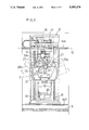
- FIGS. 1 through 4 illustrate one preferred embodiment of the invention
- FIG. 1 is a section view showing an installment condition of a spray painting apparatus according to the invention
- FIG. 2 is a front view of the apparatus
- FIG. 3 is a side view of the apparatus
- FIG. 4 is a perspective view showing the installment condition of the apparatus.
- FIG. 5 is a perspective view showing a conventional apparatus.
- numeral 1 denotes a tunnel-like painting booth
- numeral 2 denotes a conveyor device for conveying a work object A inside the booth
- numeral 3 denotes a spray painting apparatus body for spray-painting the object A.
- Substantially the entire booth ceiling is constructed as an overhead air discharge vent 4 for downwardly discharging ventilating air through the entire opening thereof.
- substantially the entire floor face is constructed as a grating floor for allowing passage of exhaust air therethrough.
- Numeral 6 denotes a cleaning-water flushing pan for receiving and flushing away dropplets of excess paint in cleaning water w.
- Numeral 7 denotes a demister for trapping and eliminating excess paint mist present in the exhaust air together with the cleaning water w by causing the combination to pass at a high velocity through a curved constricted flow passage 7a.
- the spraying apparatus 3 includes a base mount 8 movable along the object-conveying direction, a lift unit 9 integrally and liftably connected with the mount 8 and an arm 10 extending from the lift unit 9 to be pivotable about a horizontal axis P extending normal to the object-conveying direction.
- This arm 10 is attached with a pair of spray nozzles 11.
- the arm 10 is constructed as a letter-L shaped structure consisting of a base arm portion 10a extending along the pivot radius of the arm and a horizontal arm portion 10b extending along the arm pivot axis P.
- the horizontal arm portion 10b of the arm 10 includes a slide table 12 which slides to reciprocate along the arm axis P. Further, the pair of nozzles 11 are supported to the slide table 12 so that discharge axes of the nozzles extend normal to the axis P and also that the discharging ends of the nozzles are positioned on the axis P.
- the spray nozzles 11 can be appropriately positioned with respect to the object A for spray-painting the object.
- Numeral 13 denotes an operator chamber accommodating various control devices for controlling the spray painting apparatus 3.
- the base mount 8 is moved and guided by an upper rail 14a and a lower rail 14b, with the load and weight of the mount 8 being supported on the upper rail 14a. Further, a chain 15 is layed along the upper rail 14a and this chain 15 is engaged with a sprocket 16. Then, as this sprocket 16 is driven by a motor 17 mounted on the base mount 8, the chain 15 is moved to move the base mount 8 along the object-conveying direction.
- the base mount 8 mounts a pair of vertical guides 18 whereas the unit 9 is connected with a chain 19; then, a further motor 20 mounted on the base mount drives the chain 19 to lift up and down the lift unit 9 with the unit 9 being guided along the vertical guides 18.
- the arm 10 For pivotably connecting the arm 10 to the lift unit 9, the arm 10 is connected with an arm support 21 attached to the left unit acting as the support for the arm so that a base end of the base arm portion 10a can freely pivot about a pivot shaft 22. Then, for pivotably driving this construction, the base arm portion 10a of the arm 10 mounts an arc-shaped guide 23 which is coaxial with and has a larger diameter than the pivot shaft 22. On the other hand, above this guide 23, there is provided a gear 24a as a rotary member to be driven by a motor 24 fixedly mounted on the arm support 21 so as to rotate about an axis Q parallel with the arm pivot axis P.
- an open-loop chain 25 as a loop transmission means for transmitting the rotational force of the gear 24a to the arc-shaped guide 23, is entrained about this gear 24a with opposed terminal ends of the chain 25 being respectively connected with the arc-shaped guide 23 adjacent opposed edges thereof.
- the arm-pivot drive means including the motor 24 and the gear 24a effects a planetary motion relative to and along the periphery of the arc-shaped guide 23, so that the guide 23 is pivoted about the arm pivot axis P thus pivotably driving the arm 10.
- an arc-shaped rail 26 which is coaxial with the pivot shaft 22 and has a diameter even larger than the arc-shaped guide 23.
- a support arm 27 extending continuously from the base arm portion 10a carries a pair of rollers 28a and 28b which stride across to engage with the arc-shaped rail 26.
- the slide table 12 is slidable guided by means of rails 29a and 29b attached to the horizontal arm portion 10b of the arm 10 along the longitudinal direction of this horizontal arm portion 10b, i.e. along the arm pivot axis P. That is, the slide table 12 is slided back and forth as a motor 32 mounted on the horizontal arm portion 10b drives a ball screw 31 on which a ball-screw block 30 connected with the slide table 12.
- the reciprocating motion of the nozzles 11 does not cause the base end of the base arm portion 10a to approach the work object A. Therefore, there will occur no distrubance in the ventilation air flow about the object and consequently no painting quality deterioration of the object.
- Each of the nozzles 11 is guided by a spline shaft 33 so that the nozzle can slide along the longitudinal direction of the horizontal arm portion 10b relative to the slide table 12. Further, a distance between these nozzles 11 is adjustable by appropriately sliding the respective nozzles 11 relative to the slide table 12.
- Numeral 35 denotes a valve unit for switching over feed of paint to the nozzles 11. And, this valve unit 35 is attached to the horizontal arm portion 10b of the arm 10. Further, a plurality of upstream-side paint feed tubes 36 for separately feeding a plurality of kinds of paint to the nozzles 11 are caused to extend through the base mount 8, the lift unit 9 and the arm 10 to be connected with the valve unit 35. On the other hand, a plurality of downstream-side paint feed tubes for selectively feeding the plurality of kinds of paint through the valve unit 35 to the nozzles 11 are caused to extend on the arm 10 form the valve unit 35 to the nozzles 11.
Landscapes
- Engineering & Computer Science (AREA)
- Robotics (AREA)
- Spray Control Apparatus (AREA)
- Catching Or Destruction (AREA)
Applications Claiming Priority (2)
| Application Number | Priority Date | Filing Date | Title |
|---|---|---|---|
| JP1260941A JPH03123653A (ja) | 1989-10-05 | 1989-10-05 | 塗装装置 |
| JP1-260941 | 1989-10-05 |
Publications (1)
| Publication Number | Publication Date |
|---|---|
| US5085374A true US5085374A (en) | 1992-02-04 |
Family
ID=17354906
Family Applications (1)
| Application Number | Title | Priority Date | Filing Date |
|---|---|---|---|
| US07/592,671 Expired - Fee Related US5085374A (en) | 1989-10-05 | 1990-10-04 | Spray painting apparatus arm support |
Country Status (6)
| Country | Link |
|---|---|
| US (1) | US5085374A (fr) |
| EP (1) | EP0421792B1 (fr) |
| JP (1) | JPH03123653A (fr) |
| CA (1) | CA2026930C (fr) |
| DE (1) | DE69005577T2 (fr) |
| ES (1) | ES2049929T3 (fr) |
Cited By (9)
| Publication number | Priority date | Publication date | Assignee | Title |
|---|---|---|---|---|
| US5156681A (en) * | 1991-05-28 | 1992-10-20 | Eaton Corporation | Process module dispense arm |
| US5454869A (en) * | 1993-10-12 | 1995-10-03 | General Dynamics Corporation | Sealant applicator/injector |
| US5772125A (en) * | 1993-04-01 | 1998-06-30 | Sames S.A. | Machine for spraying a coating material |
| US5878952A (en) * | 1995-05-08 | 1999-03-09 | Powell; Thomas M. | Modular robot auxiliary axis system |
| US20110095094A1 (en) * | 2009-10-26 | 2011-04-28 | Arena Dust Control Innovation, LLC | Method, system or apparatus for applying a fluid to at least a portion of a floor surface of a covered area via a moveable fluid application structure |
| US20110277798A1 (en) * | 2010-05-14 | 2011-11-17 | Donald Thomas Hillier | Sample washer for drilling cuttings |
| US9573153B2 (en) | 2011-12-16 | 2017-02-21 | Durr Systems Gmbh | Coating installation and corresponding operating method |
| CN108927304A (zh) * | 2018-08-13 | 2018-12-04 | 安徽再制造工程设计中心有限公司 | 一种圆盘件内壁喷涂装置 |
| US10369583B2 (en) * | 2014-05-07 | 2019-08-06 | Dürr Systems Ag | Centrally controlled coating system for painting motor vehicle body components |
Families Citing this family (3)
| Publication number | Priority date | Publication date | Assignee | Title |
|---|---|---|---|---|
| WO1997033732A1 (fr) * | 1996-03-12 | 1997-09-18 | Giuliana Guerrieri | Procede et appareil permettant de coller des cadres, des miroirs, des plaques de verre et analogues sur des panneaux, notamment des panneaux de meubles |
| KR101089749B1 (ko) * | 2009-11-27 | 2011-12-07 | 에이피시스템 주식회사 | 도포장치 및 이의 제어 방법 |
| CN103567105B (zh) * | 2012-07-20 | 2016-06-08 | 湖南美森竹木住宅科技有限公司 | 环保安全高效喷漆装置 |
Citations (6)
| Publication number | Priority date | Publication date | Assignee | Title |
|---|---|---|---|---|
| FR1307444A (fr) * | 1960-11-30 | 1962-10-26 | Volkswagenwerk Ag | Installation pour la peinture par pulvérisation et précipitation électrostatique |
| DE2637956A1 (de) * | 1976-08-24 | 1978-03-02 | Ytong Ag | Verfahren und vorrichtung zur bespruehung von kasteninnenflaechen mit gleichmaessigen schichtdicken |
| JPS62234565A (ja) * | 1986-04-01 | 1987-10-14 | Honda Motor Co Ltd | 塗装装置 |
| GB2190312A (en) * | 1986-04-01 | 1987-11-18 | Honda Motor Co Ltd | Painting vehicle bodies |
| JPH026868A (ja) * | 1988-06-25 | 1990-01-11 | Taikisha Ltd | 塗装ブースにおける塗装装置設置方法と塗装ブースの一部を構成する塗装機操作ユニット |
| US4931322A (en) * | 1986-04-01 | 1990-06-05 | Honda Giken Kogyo Kabushiki | Method and apparatus for painting object |
-
1989
- 1989-10-05 JP JP1260941A patent/JPH03123653A/ja active Pending
-
1990
- 1990-10-04 EP EP90310887A patent/EP0421792B1/fr not_active Expired - Lifetime
- 1990-10-04 ES ES90310887T patent/ES2049929T3/es not_active Expired - Lifetime
- 1990-10-04 DE DE69005577T patent/DE69005577T2/de not_active Expired - Fee Related
- 1990-10-04 US US07/592,671 patent/US5085374A/en not_active Expired - Fee Related
- 1990-10-04 CA CA002026930A patent/CA2026930C/fr not_active Expired - Fee Related
Patent Citations (7)
| Publication number | Priority date | Publication date | Assignee | Title |
|---|---|---|---|---|
| FR1307444A (fr) * | 1960-11-30 | 1962-10-26 | Volkswagenwerk Ag | Installation pour la peinture par pulvérisation et précipitation électrostatique |
| DE2637956A1 (de) * | 1976-08-24 | 1978-03-02 | Ytong Ag | Verfahren und vorrichtung zur bespruehung von kasteninnenflaechen mit gleichmaessigen schichtdicken |
| JPS62234565A (ja) * | 1986-04-01 | 1987-10-14 | Honda Motor Co Ltd | 塗装装置 |
| GB2190312A (en) * | 1986-04-01 | 1987-11-18 | Honda Motor Co Ltd | Painting vehicle bodies |
| US4931322A (en) * | 1986-04-01 | 1990-06-05 | Honda Giken Kogyo Kabushiki | Method and apparatus for painting object |
| JPH026868A (ja) * | 1988-06-25 | 1990-01-11 | Taikisha Ltd | 塗装ブースにおける塗装装置設置方法と塗装ブースの一部を構成する塗装機操作ユニット |
| US4951600A (en) * | 1988-06-25 | 1990-08-28 | Taikisha, Ltd. | Painting machine and control unit for use in a painting booth |
Cited By (11)
| Publication number | Priority date | Publication date | Assignee | Title |
|---|---|---|---|---|
| US5156681A (en) * | 1991-05-28 | 1992-10-20 | Eaton Corporation | Process module dispense arm |
| US5772125A (en) * | 1993-04-01 | 1998-06-30 | Sames S.A. | Machine for spraying a coating material |
| US5454869A (en) * | 1993-10-12 | 1995-10-03 | General Dynamics Corporation | Sealant applicator/injector |
| US5878952A (en) * | 1995-05-08 | 1999-03-09 | Powell; Thomas M. | Modular robot auxiliary axis system |
| US20110095094A1 (en) * | 2009-10-26 | 2011-04-28 | Arena Dust Control Innovation, LLC | Method, system or apparatus for applying a fluid to at least a portion of a floor surface of a covered area via a moveable fluid application structure |
| US8777123B2 (en) * | 2009-10-26 | 2014-07-15 | Arena Dust Control Innovation, LLC | Method, system or apparatus for applying a fluid to at least a portion of a floor surface of a covered area via a moveable fluid application structure |
| US20110277798A1 (en) * | 2010-05-14 | 2011-11-17 | Donald Thomas Hillier | Sample washer for drilling cuttings |
| US9573153B2 (en) | 2011-12-16 | 2017-02-21 | Durr Systems Gmbh | Coating installation and corresponding operating method |
| US10369583B2 (en) * | 2014-05-07 | 2019-08-06 | Dürr Systems Ag | Centrally controlled coating system for painting motor vehicle body components |
| CN108927304A (zh) * | 2018-08-13 | 2018-12-04 | 安徽再制造工程设计中心有限公司 | 一种圆盘件内壁喷涂装置 |
| CN108927304B (zh) * | 2018-08-13 | 2020-08-04 | 安徽再制造工程设计中心有限公司 | 一种圆盘件内壁喷涂装置 |
Also Published As
| Publication number | Publication date |
|---|---|
| EP0421792B1 (fr) | 1993-12-29 |
| EP0421792A2 (fr) | 1991-04-10 |
| DE69005577T2 (de) | 1994-07-14 |
| ES2049929T3 (es) | 1994-05-01 |
| CA2026930A1 (fr) | 1991-04-06 |
| DE69005577D1 (de) | 1994-02-10 |
| JPH03123653A (ja) | 1991-05-27 |
| EP0421792A3 (en) | 1991-09-11 |
| CA2026930C (fr) | 1997-09-30 |
Similar Documents
| Publication | Publication Date | Title |
|---|---|---|
| US5085374A (en) | Spray painting apparatus arm support | |
| US4762013A (en) | Reciprocating device for spray coating | |
| CN113893977A (zh) | 一种铝型材液体涂料和粉体喷涂装置 | |
| US4864965A (en) | Automatic painting apparatus | |
| US5186394A (en) | Remote controlled freely pivotal nozzle | |
| US4518298A (en) | Head for industrial robot | |
| US3286688A (en) | Paint spraying apparatus | |
| CN113770554A (zh) | 一种塑料件激光切割设备 | |
| CN120683983A (zh) | 一种砂浆喷涂装置及控制方法 | |
| JPH07158252A (ja) | ライニング吹付装置 | |
| JP2837754B2 (ja) | 塗装用ロボット | |
| CN223836536U (zh) | 一种可调匀料板及振动输送机 | |
| JPH0128856Y2 (fr) | ||
| CN221413626U (zh) | 具有自动化喷涂及voc回收功能的装置 | |
| JPS5854619B2 (ja) | 塗装装置 | |
| US3386414A (en) | Decorative painting apparatus | |
| CN222161894U (zh) | 一种建筑装饰装修用喷涂装置 | |
| CN211488316U (zh) | 一种飞机生产用涂料装置 | |
| JPH01299664A (ja) | サイドレシプロ装置 | |
| JPH0433976Y2 (fr) | ||
| JPH0344306Y2 (fr) | ||
| CN116174900A (zh) | 一种用于激光焊接的机械手 | |
| CN120443823A (zh) | 一种罩面建筑材料自动刮涂往复抹头装置 | |
| CN210357839U (zh) | 一种点胶装置 | |
| CN117983464A (zh) | 一种基于激光扫描的涂装装置 |
Legal Events
| Date | Code | Title | Description |
|---|---|---|---|
| AS | Assignment |
Owner name: TAIKISHA, LTD., 1-GO, 6-BAN, 2-CHOME, NISHI-SHINJU Free format text: ASSIGNMENT OF ASSIGNORS INTEREST.;ASSIGNORS:ASAMI, KOUICHIRO;NAGASAKI, HEISHIRO;OKUDA, MASAHARU;REEL/FRAME:005548/0016 Effective date: 19901126 |
|
| CC | Certificate of correction | ||
| FEPP | Fee payment procedure |
Free format text: PAYOR NUMBER ASSIGNED (ORIGINAL EVENT CODE: ASPN); ENTITY STATUS OF PATENT OWNER: LARGE ENTITY |
|
| FPAY | Fee payment |
Year of fee payment: 4 |
|
| FPAY | Fee payment |
Year of fee payment: 8 |
|
| REMI | Maintenance fee reminder mailed | ||
| LAPS | Lapse for failure to pay maintenance fees | ||
| FP | Lapsed due to failure to pay maintenance fee |
Effective date: 20040204 |
|
| STCH | Information on status: patent discontinuation |
Free format text: PATENT EXPIRED DUE TO NONPAYMENT OF MAINTENANCE FEES UNDER 37 CFR 1.362 |