US5102239A - Ceramic bearing - Google Patents
Ceramic bearing Download PDFInfo
- Publication number
- US5102239A US5102239A US07/759,825 US75982591A US5102239A US 5102239 A US5102239 A US 5102239A US 75982591 A US75982591 A US 75982591A US 5102239 A US5102239 A US 5102239A
- Authority
- US
- United States
- Prior art keywords
- sliding
- sliding surface
- ring
- ceramic
- inner ring
- Prior art date
- Legal status (The legal status is an assumption and is not a legal conclusion. Google has not performed a legal analysis and makes no representation as to the accuracy of the status listed.)
- Expired - Fee Related
Links
Images



Classifications
-
- F—MECHANICAL ENGINEERING; LIGHTING; HEATING; WEAPONS; BLASTING
- F16—ENGINEERING ELEMENTS AND UNITS; GENERAL MEASURES FOR PRODUCING AND MAINTAINING EFFECTIVE FUNCTIONING OF MACHINES OR INSTALLATIONS; THERMAL INSULATION IN GENERAL
- F16C—SHAFTS; FLEXIBLE SHAFTS; ELEMENTS OR CRANKSHAFT MECHANISMS; ROTARY BODIES OTHER THAN GEARING ELEMENTS; BEARINGS
- F16C33/00—Parts of bearings; Special methods for making bearings or parts thereof
- F16C33/02—Parts of sliding-contact bearings
- F16C33/04—Brasses; Bushes; Linings
- F16C33/043—Sliding surface consisting mainly of ceramics, cermets or hard carbon, e.g. diamond like carbon [DLC]
-
- F—MECHANICAL ENGINEERING; LIGHTING; HEATING; WEAPONS; BLASTING
- F16—ENGINEERING ELEMENTS AND UNITS; GENERAL MEASURES FOR PRODUCING AND MAINTAINING EFFECTIVE FUNCTIONING OF MACHINES OR INSTALLATIONS; THERMAL INSULATION IN GENERAL
- F16C—SHAFTS; FLEXIBLE SHAFTS; ELEMENTS OR CRANKSHAFT MECHANISMS; ROTARY BODIES OTHER THAN GEARING ELEMENTS; BEARINGS
- F16C17/00—Sliding-contact bearings for exclusively rotary movement
- F16C17/10—Sliding-contact bearings for exclusively rotary movement for both radial and axial load
-
- F—MECHANICAL ENGINEERING; LIGHTING; HEATING; WEAPONS; BLASTING
- F16—ENGINEERING ELEMENTS AND UNITS; GENERAL MEASURES FOR PRODUCING AND MAINTAINING EFFECTIVE FUNCTIONING OF MACHINES OR INSTALLATIONS; THERMAL INSULATION IN GENERAL
- F16C—SHAFTS; FLEXIBLE SHAFTS; ELEMENTS OR CRANKSHAFT MECHANISMS; ROTARY BODIES OTHER THAN GEARING ELEMENTS; BEARINGS
- F16C17/00—Sliding-contact bearings for exclusively rotary movement
- F16C17/12—Sliding-contact bearings for exclusively rotary movement characterised by features not related to the direction of the load
- F16C17/18—Sliding-contact bearings for exclusively rotary movement characterised by features not related to the direction of the load with floating brasses or brushing, rotatable at a reduced speed
-
- F—MECHANICAL ENGINEERING; LIGHTING; HEATING; WEAPONS; BLASTING
- F16—ENGINEERING ELEMENTS AND UNITS; GENERAL MEASURES FOR PRODUCING AND MAINTAINING EFFECTIVE FUNCTIONING OF MACHINES OR INSTALLATIONS; THERMAL INSULATION IN GENERAL
- F16C—SHAFTS; FLEXIBLE SHAFTS; ELEMENTS OR CRANKSHAFT MECHANISMS; ROTARY BODIES OTHER THAN GEARING ELEMENTS; BEARINGS
- F16C2300/00—Application independent of particular apparatuses
- F16C2300/20—Application independent of particular apparatuses related to type of movement
- F16C2300/22—High-speed rotation
-
- Y—GENERAL TAGGING OF NEW TECHNOLOGICAL DEVELOPMENTS; GENERAL TAGGING OF CROSS-SECTIONAL TECHNOLOGIES SPANNING OVER SEVERAL SECTIONS OF THE IPC; TECHNICAL SUBJECTS COVERED BY FORMER USPC CROSS-REFERENCE ART COLLECTIONS [XRACs] AND DIGESTS
- Y10—TECHNICAL SUBJECTS COVERED BY FORMER USPC
- Y10S—TECHNICAL SUBJECTS COVERED BY FORMER USPC CROSS-REFERENCE ART COLLECTIONS [XRACs] AND DIGESTS
- Y10S384/00—Bearings
- Y10S384/90—Cooling or heating
- Y10S384/901—Floating bushing
Definitions
- the invention relates to a ceramic bearing comprising a ceramic outer ring, a ceramic inner ring, and a ceramic sliding ring which is fitted between the ceramic outer ring and the ceramic inner ring.
- a bearing such as a sliding bearing or a roller bearing is commonly used for housing a rotating shaft in an assembly.
- the roller bearings comprise rolling members such as balls, rollers, or needles, which are positioned between an outer ring fitted into a housing provided in a mechanical frame, and an inner ring into which the rotating shaft is installed.
- the roller bearings are classified as ball, roller, or needle bearings according to the type of rolling member used (Japanese Patent Publication No. 49-41231).
- roller bearings deep-groove type, angular ball type, and tapered-roller type bearings are used for supporting a shaft to which radial and thrust loads are applied at the same time.
- sliding bearings include a steel, cast iron, or copper support upon which a white metal layer is laminated and formed to a predetermined dimension by machining.
- Others of the sliding bearings include a copper or gun-metal support having an oil-impregnated alloy which is laminated upon or embedded into the support.
- a sliding bearing having a sleeve-shaped support is known as a bearing for supporting radial loads (Japanese Patent Publication No. 49-18885).
- a sliding bearing having a metal support formed in disk-shape is known for supporting thrust loads (Japanese Patent Publication No. 49-678).
- roller and sliding bearings are standardized, being commonly available and having common features. In practice, these bearings are designed and selected according to the requirements of the application for which they will be used. However, the known sliding and roller bearings are deficient in some areas.
- roller bearings A number of problems may arise with the known roller bearings. Flaking of rolling members due to fatigue limits service life, and worn rolling members make the bearing noisy.
- the roller bearings have low heat resistance. Additionally, the roller bearings are costly due to a relatively larger number of components.
- the known sliding bearings exhibit a different and distinct set of problems. Sliding friction between an outside circumference of a shaft journal and an inside circumference of the bearing generates heat. The amount of heat generated depends on the load applied to the shaft and the sliding speed. The amount of heat increases as the sliding speed and/or load increases. The heat causes thermal expansion of the shaft and the bearing, and is likely to adversely affect smooth rotation of the shaft. In addition, as the shaft journal and the inside circumference of the bearing slide in close contact with each other, wear results on the shaft and the bearing, and the wear also may obstruct the smooth rotation of the shaft.
- a load per unit area which the sliding bearing can support depends on the bearing material.
- iron or copper-based metal is the material employed; however, the allowable load per unit area for the metals is smaller than that for ceramics. Therefore, a large bearing area is needed to support a large load, and the size of the sliding bearing becomes quite large.
- a sleeve-shaped radial bearing and a disk-shaped thrust bearing must be utilized in combination, or a bearing suitable for the application must be designed each time.
- a ceramic bearing having a ceramic sliding ring which is fitted between a ceramic outer ring and a ceramic inner ring.
- the ceramic sliding ring (to be called the “sliding ring”) is positioned between the ceramic outer (to be called the “outer ring”) and the ceramic inner ring (to be called the “inner ring”).
- the ceramic outer to be called the “outer ring”
- the ceramic inner ring to be called the “inner ring”
- a sliding surface is formed between an outside circumference of the inner ring and an inside circumference of the sliding ring, and another sliding surface is formed between an outside circumference of the sliding ring and an inside circumference of the otter ring.
- the relative sliding speed at each sliding surface is lower than the sliding speed between an outer ring and inner ring when arranged to rotate in direct sliding contact with each other, and heat and wear produced on each sliding surface is reduced.
- the sliding speed on each sliding surface is a design specification, and the bearing can support a shaft rotating at a higher speed than the conventional sliding bearings will permit. Moreover, no sliding takes place between the inner ring, which is fixed to the shaft journal, and the shaft. Thus, the shaft never wears down.
- the bearing according to the invention may comprise a plurality of sliding rings fitted between the outer and inner rings, and sliding surfaces corresponding to the number of fitted sliding rings. Thus it is possible to lower the sliding speed and to reduce heat and wear on each of the sliding surfaces.
- FIG. 1(A) is a sectional view illustrating the bearing of a first embodiment of the present invention.
- FIG. 1(B) is an exploded perspective view illustrating components of the bearing of the first embodiment.
- FIG. 2 is a cross-sectional view illustrating the bearing of a second embodiment of the invention.
- FIG. 3 is a cross-sectional view illustrating the bearing of a third embodiment of the invention.
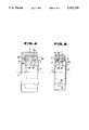
- FIG. 4 is a cross sectional view illustrating the bearing of a fourth embodiment of the invention.
- FIG. 5 is a cross-sectional view illustrating the bearing of a fifth embodiment of the invention.
- FIG. 6(A) is a cross-sectional view illustrating the bearing of the sixth embodiment of the invention.
- FIG. 6(B) is an exploded perspective view illustrating components of the bearing of the sixth embodiment.
- a bearing according to the invention comprises an outer ring 1, an inner ring 2, and a sliding ring 3 which is fitted between the outer ring 1 and the inner ring 2.
- the outer ring 1 is produced through a process using an oxide ceramic material based on Partially-Stabilized-Zirconia (to be called "PSZ” hereinafter) or alumina, which is charged into a mold and is press-formed, and the molded compact ring is sintered at 1500° C. to 1600° C.
- PSZ Partially-Stabilized-Zirconia
- the outer ring is formed with a cylindrical outside circumference portion 1a and end faces 1b and 1c.
- the outside circumference portion 1a is dimensioned for installation in a housing which is provided in a machine.
- the outside circumference portion 1a is made parallel to an axial center 4 of the outer ring 1, to a predetermined diameter and close tolerance.
- the end face 1b has a through bore 5.
- the inside circumference of the outer ring 1 defines a sliding surface 1d which has a predetermined length in the axial direction from the end face 1c.
- the sliding surface 1d has a cylindrical-shape and is parallel to the axial center 4.
- a tapered surface 1e is formed between the sliding surface 1d and the through bore 5, and the outer ring 1 incorporates a circumferential protrusion 1f on the inside circumference at the side of end face 1b.
- the inner ring 2 is produced through a process using an oxide ceramic material of PSZ or alumina which is charged into a mold and press-formed, and the molded compact ring is sintered at 1500° C. to 1600° C.
- the inner ring 2 is formed with a flange-shaped, circumferential protrusion 2a, a cylindrical sliding surface 2b, and end faces 2c and 2d.
- a tapered surface 2e is formed between the sliding surface 2b and the flange-shaped, circumferential protrusion 2a.
- the inner ring 2 has a bore 6 which is coaxial with the axial center 4, and a shaft (not shown) is fitted into the bore 6.
- the shaft-fitting bore 6 is formed with a pre-determined diameter held to a close tolerance, for fixedly receiving a shaft to which a radial load, a thrust load, or the resultant load of said loads is applied.
- the end face 2d also is provided as a face to which the thrust load is transmitted, in contact with an end face of the shaft.
- the sliding ring 3 is produced through a process using an oxide ceramic material of PSZ or alumina which is charged into a mold and press-formed, and the molded compact ring is sintered at 1500° C. to 1600° C.
- the sliding ring 3 is sleeve-shaped, and the outside circumference of the sliding ring 3 defines a sliding surface 3a in sliding contact with the sliding surface 1d formed on the inside circumference of the outer ring 1.
- the sliding surface 3a holds a predetermined tolerance relative to the sliding surface 1d of the outer ring 1.
- the inside circumference of the sliding ring 3 also defines a sliding surface 3b in sliding contact with the sliding surface 2b on the outside circumference of the inner ring 2, and the sliding surface 3b holds a predetermined tolerance relative to the sliding surface 2b on the inner ring 2.
- the sliding ring 3 defines an end face 3c which abuts tapered surface 1e, or neck portion 1g of said tapered surface 1e, on the inside circumference of the outer ring 1.
- the sliding ring 3 also defines an end face 3d which may abut a tapered surface 2e, or a neck portion 2f of said tapered surface 2e, on the outside circumference of the inner ring 2.
- a journal portion (not shown) of the shaft is fixed in the shaft-fitting bore 6 in the inner ring 2, and a radial load applied to the shaft is transmitted from the inner ring 2, through the sliding ring 3, to the outer ring 1.
- a thrust load is applied to the shaft, a stepped diameter portion of the shaft abuts the end face 2d of the inner ring 2, and thereby the thrust load is transmitted from the inner ring 2, through the sliding ring 3, to the outer ring 1.
- sliding speeds i.e., the difference between rotating speeds, for each pair of sliding surfaces will be approximately the same and in each case will be smaller than if the inner and outer rings were in direct sliding contact with each other.
- the inner ring 2 rotates at the same speed as the shaft.
- the thrust load is transmitted from the neck portion 2f of the tapered surface 2e on the outside circumference of said inner ring 2, to the end face 3d of the sliding ring 3. Sliding contact occurs between the neck portion 2f and the end face 3d.
- FIG. 2 is a cross-sectional view of a bearing according to a second embodiment of the invention, wherein a sliding ring 9 having a circular cross-section is fitted between an outer ring 7 and an inner ring 8.
- the outer ring 7, the inner ring 8, and the sliding ring 9 are press-formed from an oxide ceramic material based on PSZ or alumina, and are sintered at 1500° C. to 1600° C.
- the inside circumference of the outer ring 7 defines a through bore 5 and a sliding surface 7a which is parallel to an axial center 4. Said sliding surface 7a has a diameter larger than that of the through bore 5.
- a circumferential protrusion 7b is defined between the through bore 5 and the sliding surface 7a. The height of said protrusion 7b is slightly larger than one-half of the thickness of the sliding ring 9, that is, slightly larger than a radius of the sliding ring 9.
- An outside circumference of the inner ring 8 defines a flange-shaped protrusion 8a and a sliding surface 8b.
- a riser portion 8c between the flange-shaped protrusion 8a and the sliding surface 8b has a height which is slightly greater than one-half of the thickness of the sliding ring 9, that is, slightly greater than the radius of the sliding ring 9.
- the sliding ring 9 has a circular cross-section of predetermined radius, and sliding portions 9a, 9b, 9c and 9d refer to an outside circumferential portion, an inside circumferential portion and each end face, respectively.
- the sliding portion 9a on the outside circumference of the sliding ring 9 is in contact with the sliding surface 7a on the inside circumference of the outer ring 7.
- the sliding portion 9b is in contact with the sliding surface 8b on the outside circumference of the inner ring 8;
- the sliding portion 9c is in contact with a riser portion of the protrusion 7b on the inside circumference of the outer ring 7;
- the sliding portion 9d is in contact with the riser portion 8c on the outside circumference of the inner ring 8.
- the bearing is constructed so that it is capable of supporting radial and thrust loads applied to a shaft (not shown) fixed to the inner ring 8.
- the cross-section of the sliding ring 9 is circular and relatively small, the bearing can be relatively compact.
- FIG. 3 is a cross-sectional view of a bearing according to a third embodiment of the invention, wherein a sliding ring 10 having an elliptic cross-section is fitted between an outer ring 7 and an inner ring 8.
- An outside circumferential surface of the sliding ring 10 defines a sliding surface 10a which is in contact with a sliding surface 7a defined by an inside circumferential surface of the outer ring 7.
- An inside circumferential surface of the sliding ring 10 defines a sliding surface 10b which is in contact with a sliding surface 8b defined by an outside circumferential surface of the inner ring 8.
- the sliding ring 10 has round-shaped ends. One of the ends defines a sliding surface 10c which is in contact with a riser portion of the protrusion 7b of the outer ring 7, and another of the ends defines a sliding surface 10d which is in contact with a riser portion 8c of the inner ring 8.
- the bearing of this embodiment can support radial and thrust loads which are applied to a shaft (not shown) fixed to the inner ring 8. Since the cross-section of the sliding ring 10 is elliptical in shape, the sliding ring 10 has a relatively large radial loading area.
- FIG. 4 is a cross sectional view of a bearing according to a fourth embodiment of the invention, wherein a sliding ring having an L-shaped cross-section is fitted between the outer ring 7 of the embodiment shown in FIG. 2, and the inner ring 2 of the embodiment shown in FIG. 1.
- the bearing of this embodiment is capable of employing the whole sliding surface 2b, defined by the outside circumference of the inner ring 2 and the outside circumference of the flange-shaped protrusion 2a, as a loaded area, and thus can support a large radial load.
- FIG. 5 is a cross-sectional view of a bearing according to a fifth embodiment of the invention, wherein a sliding ring 12 having a Z-shaped cross-section is fitted between the outer ring 1 and the inner ring 2 of the embodiment shown in FIG. 1.
- the bearing of this embodiment can employ the whole of sliding surface 2b, defined by the outside circumference of the inner ring 2 and the outside circumferential surface of the flange-shaped protrusion 2a, as a loaded area. Thereby, the bearing of this embodiment can support a large load.
- FIGS. 6(A) and (B) illustrate a bearing according to a sixth embodiment of the invention, wherein a plurality of sliding rings are fitted between the outer ring 1 and inner ring 2.
- the outer ring 1 and inner ring 2 are similar to those shown in the embodiment of FIG. 1.
- Sliding rings 14 and 15 are held by a retainer 13 and are fitted between the outer ring 1 and the inner ring 2.
- the sliding rings 14 and 15 and the retainer 13 are made from the same material in the same manner as the sliding ring 3 shown in FIG. 1.
- the sliding ring 14 is sleeve-shaped, and an outside circumferential surface defines a sliding surface 14a which is in sliding contact with sliding surface 1d defined by the inside circumference of the outer ring 1. Another end face of the sliding ring 14 defines sliding surface 14d which is in sliding contact with a flange 13d of the retainer 13, and the sliding ring 14 is rotatably slidable on the sliding surface 13a of the retainer 13.
- the sliding ring 15 is sleeve-shaped, and an inside circumferential surface defines a sliding surface 15a which is in sliding contact with a sliding surface 2b defined by the outside circumference of the inner ring 2.
- An outside circumferential surface of the sliding ring 15 defines a sliding surface 15b which is in sliding contact with an inside circumferential surface 13b of the retainer 13.
- One end face of the sliding ring 15 defines a sliding face 15c which is in sliding contact with a flange 13c of the retainer 13.
- Another end face defines a sliding face 15d which is in sliding contact with a neck portion 2f of a tapered surface 2e defined by the outside circumference of the inner ring 2, and the sliding ring 15 is rotatably slidable on the surface 13b of the retainer 13.
- the retainer 13 can be formed by melt-bonding flange portions 13c and 13d on both ends of a sleeve-shaped ring, or by melt-bonding a flange on one end of T-shaped ring.
- the bearing of the sixth embodiment above described four sliding surfaces are defined by the sliding rings 14, 15 and the retainer 13, and the outer and inner rings 1 and 2. Accordingly, the rotating speed of the shaft fixed to the inner ring 2 is divided among the four sliding surfaces, and thus a sliding speed on each sliding surface can be decreased, thereby reducing heat and wear caused by friction on each sliding surface. Additionally, when the sliding speed on each sliding surface is allowed to approach a predetermined maximum, the bearing can support a shaft rotating at a higher speed than the prior art bearings would allow.
- each sliding surface of the outer ring, the inner ring and the sliding ring can be additionally finish treated by lapping, if necessary.
- the lapping may be done separately on each of the outer, inner, and sliding rings, or may be selectively done by rubbing the rings together with abrasive such as diamond powder applied to the surfaces between the rings. Lapping each sliding surface permits the bearing to rotate more smoothly.
- the outer, inner, and sliding rings slide on the sliding surface in contact with each other, and heat is naturally generated by sliding friction.
- each of the rings is made from ceramic material, heat affects the bearing less than it would if the bearing was made of metal. Since a coefficient of thermal expansion of ceramic is 3 to 11 ⁇ 10 -6 /°C., excessive stress will not be produced by thermal expansion, and thermal deterioration will not occur.
Landscapes
- Engineering & Computer Science (AREA)
- General Engineering & Computer Science (AREA)
- Mechanical Engineering (AREA)
- Chemical & Material Sciences (AREA)
- Ceramic Engineering (AREA)
- Sliding-Contact Bearings (AREA)
Applications Claiming Priority (2)
| Application Number | Priority Date | Filing Date | Title |
|---|---|---|---|
| JP1022576A JPH0814284B2 (ja) | 1989-02-02 | 1989-02-02 | セラミックス製軸受 |
| JP1-22576 | 1989-02-02 |
Related Parent Applications (1)
| Application Number | Title | Priority Date | Filing Date |
|---|---|---|---|
| US07473657 Continuation | 1990-02-01 |
Publications (1)
| Publication Number | Publication Date |
|---|---|
| US5102239A true US5102239A (en) | 1992-04-07 |
Family
ID=12086696
Family Applications (1)
| Application Number | Title | Priority Date | Filing Date |
|---|---|---|---|
| US07/759,825 Expired - Fee Related US5102239A (en) | 1989-02-02 | 1991-09-13 | Ceramic bearing |
Country Status (7)
| Country | Link |
|---|---|
| US (1) | US5102239A (de) |
| EP (1) | EP0381336B1 (de) |
| JP (1) | JPH0814284B2 (de) |
| AT (1) | ATE123116T1 (de) |
| AU (1) | AU628125B2 (de) |
| CA (1) | CA2009028A1 (de) |
| DE (1) | DE69019542T2 (de) |
Cited By (14)
| Publication number | Priority date | Publication date | Assignee | Title |
|---|---|---|---|---|
| US5575571A (en) * | 1993-11-02 | 1996-11-19 | Koyo Seiko Co., Ltd. | Rolling bearing |
| US5577401A (en) * | 1995-11-15 | 1996-11-26 | Monarch Knitting Machinery Corp. | Knitting machine cylinder having a hardened top insert ring and method of making same |
| US5618107A (en) * | 1996-06-07 | 1997-04-08 | A&B Process Systems Corporation | Bearing assembly for agitator shaft |
| US5667311A (en) * | 1995-03-27 | 1997-09-16 | Maers; Walter | Pivot shaft for a damper assembly |
| US6505974B2 (en) | 2001-05-02 | 2003-01-14 | Honeywell International, Inc. | Ceramic ball bearings and assembly |
| US20060147139A1 (en) * | 2005-01-06 | 2006-07-06 | Snecma | Member for the guidance of a movable piece |
| US20060239845A1 (en) * | 2003-07-30 | 2006-10-26 | Yasuharu Yamamoto | Pump |
| US20070223852A1 (en) * | 2006-03-21 | 2007-09-27 | Lee Yu H | Ceramic bearing |
| US20110193437A1 (en) * | 2010-02-11 | 2011-08-11 | Robert Bosch Gmbh | Driving device, in particular electric motor, for driving a unit |
| US20120087608A1 (en) * | 2010-10-07 | 2012-04-12 | Robert Bosch Gmbh | Sliding bearing, process for producing a sliding bearing and use of a sliding bearing |
| US20130068057A1 (en) * | 2011-09-16 | 2013-03-21 | Hamilon Sundstrand Corporation | Idler gear assembly for a generator |
| CN104948569A (zh) * | 2014-03-24 | 2015-09-30 | 联想(北京)有限公司 | 一种电子设备和连接装置 |
| CN108223584A (zh) * | 2016-12-09 | 2018-06-29 | 斯凯孚公司 | 组成部件和组成部件的制造方法 |
| US10913610B2 (en) | 2019-04-12 | 2021-02-09 | Sst Systems, Inc. | Conveyor roller turn |
Families Citing this family (7)
| Publication number | Priority date | Publication date | Assignee | Title |
|---|---|---|---|---|
| AU634735B2 (en) * | 1988-12-26 | 1993-03-04 | Wing Highcera Co. Ltd. | Ceramic bearing and manufacturing method |
| KR960000986B1 (ko) * | 1989-10-02 | 1996-01-15 | 가부시끼가이샤 윙· 하이세라 | 세라믹제 축받이 |
| GB0007034D0 (en) | 2000-03-23 | 2000-05-10 | Geco As | Seismic source arrays |
| DE10211083A1 (de) * | 2002-03-13 | 2003-11-27 | Zf Lenksysteme Gmbh | Getriebe |
| DE102006019873B3 (de) * | 2006-04-28 | 2007-10-18 | Siemens Ag | Fanglager für eine elektrische Maschine sowie elektrische Maschine mit zumindest einem derartigen Fanglager |
| BRPI0909160A2 (pt) | 2008-04-09 | 2019-09-24 | Saint Gobain Performance Plastics Corp | rolamentos |
| KR101981090B1 (ko) * | 2015-11-10 | 2019-05-22 | 가부시키가이샤 하모닉 드라이브 시스템즈 | 미끄럼 베어링 |
Citations (7)
| Publication number | Priority date | Publication date | Assignee | Title |
|---|---|---|---|---|
| GB107152A (en) * | 1916-11-07 | 1917-06-21 | Thomas Reid Mccallum | An Improved Bearing. |
| US3056637A (en) * | 1959-03-02 | 1962-10-02 | Garlock Inc | Bearing |
| US3279721A (en) * | 1964-10-30 | 1966-10-18 | Boeing Co | Bearing arrangement for variable sweep wing aircraft |
| US3920293A (en) * | 1974-04-23 | 1975-11-18 | Hirokazu Takeuchi | Bearing made of plastics |
| US4427309A (en) * | 1980-03-24 | 1984-01-24 | The Garrett Corporation | Turbocharger shaft bearing |
| US4664595A (en) * | 1983-09-30 | 1987-05-12 | Ebara Corporation | Combination of slide members |
| JPS63167124A (ja) * | 1986-12-26 | 1988-07-11 | Brother Ind Ltd | 摺動装置 |
Family Cites Families (7)
| Publication number | Priority date | Publication date | Assignee | Title |
|---|---|---|---|---|
| JPS5521519B2 (de) * | 1973-05-10 | 1980-06-10 | ||
| GB1437532A (en) * | 1973-06-29 | 1976-05-26 | Sealed Motor Const Co Ltd | Pump units |
| JPS51133649A (en) * | 1975-05-16 | 1976-11-19 | Toyohiko Naono | Sliding mechanism |
| JPS6029012B2 (ja) * | 1979-01-22 | 1985-07-08 | 京セラ株式会社 | セラミック摺動装置 |
| GB2182105B (en) * | 1983-10-21 | 1988-10-26 | Daido Metal Co | Composite sliding and/or bearing structure |
| JPS6191067A (ja) * | 1984-10-10 | 1986-05-09 | 株式会社東芝 | 摺動部材 |
| JPS63149408A (ja) * | 1986-12-15 | 1988-06-22 | Isuzu Motors Ltd | タ−ボチヤ−ジヤ等の軸受装置 |
-
1989
- 1989-02-02 JP JP1022576A patent/JPH0814284B2/ja not_active Expired - Fee Related
-
1990
- 1990-01-18 AT AT90300514T patent/ATE123116T1/de not_active IP Right Cessation
- 1990-01-18 EP EP90300514A patent/EP0381336B1/de not_active Expired - Lifetime
- 1990-01-18 DE DE69019542T patent/DE69019542T2/de not_active Expired - Fee Related
- 1990-01-31 CA CA002009028A patent/CA2009028A1/en not_active Abandoned
- 1990-01-31 AU AU48945/90A patent/AU628125B2/en not_active Ceased
-
1991
- 1991-09-13 US US07/759,825 patent/US5102239A/en not_active Expired - Fee Related
Patent Citations (7)
| Publication number | Priority date | Publication date | Assignee | Title |
|---|---|---|---|---|
| GB107152A (en) * | 1916-11-07 | 1917-06-21 | Thomas Reid Mccallum | An Improved Bearing. |
| US3056637A (en) * | 1959-03-02 | 1962-10-02 | Garlock Inc | Bearing |
| US3279721A (en) * | 1964-10-30 | 1966-10-18 | Boeing Co | Bearing arrangement for variable sweep wing aircraft |
| US3920293A (en) * | 1974-04-23 | 1975-11-18 | Hirokazu Takeuchi | Bearing made of plastics |
| US4427309A (en) * | 1980-03-24 | 1984-01-24 | The Garrett Corporation | Turbocharger shaft bearing |
| US4664595A (en) * | 1983-09-30 | 1987-05-12 | Ebara Corporation | Combination of slide members |
| JPS63167124A (ja) * | 1986-12-26 | 1988-07-11 | Brother Ind Ltd | 摺動装置 |
Cited By (20)
| Publication number | Priority date | Publication date | Assignee | Title |
|---|---|---|---|---|
| US5575571A (en) * | 1993-11-02 | 1996-11-19 | Koyo Seiko Co., Ltd. | Rolling bearing |
| US5667311A (en) * | 1995-03-27 | 1997-09-16 | Maers; Walter | Pivot shaft for a damper assembly |
| US5577401A (en) * | 1995-11-15 | 1996-11-26 | Monarch Knitting Machinery Corp. | Knitting machine cylinder having a hardened top insert ring and method of making same |
| US5618107A (en) * | 1996-06-07 | 1997-04-08 | A&B Process Systems Corporation | Bearing assembly for agitator shaft |
| US6505974B2 (en) | 2001-05-02 | 2003-01-14 | Honeywell International, Inc. | Ceramic ball bearings and assembly |
| US6746156B2 (en) | 2001-05-02 | 2004-06-08 | Honeywell International, Inc. | Ceramic ball bearings and assembly |
| US7416344B2 (en) | 2003-07-30 | 2008-08-26 | Mitsubishi Heavy Industries, Ltd. | Pump carrying supercritical fluid with ceramic bearings |
| US20060239845A1 (en) * | 2003-07-30 | 2006-10-26 | Yasuharu Yamamoto | Pump |
| US7695194B2 (en) * | 2005-01-06 | 2010-04-13 | Snecma | Member for the guidance of a movable piece |
| US20060147139A1 (en) * | 2005-01-06 | 2006-07-06 | Snecma | Member for the guidance of a movable piece |
| US20070223852A1 (en) * | 2006-03-21 | 2007-09-27 | Lee Yu H | Ceramic bearing |
| US20110193437A1 (en) * | 2010-02-11 | 2011-08-11 | Robert Bosch Gmbh | Driving device, in particular electric motor, for driving a unit |
| US8593025B2 (en) * | 2010-02-11 | 2013-11-26 | Robert Bosch Gmbh | Driving device, in particular electric motor, for driving a unit |
| US20120087608A1 (en) * | 2010-10-07 | 2012-04-12 | Robert Bosch Gmbh | Sliding bearing, process for producing a sliding bearing and use of a sliding bearing |
| US8641285B2 (en) * | 2010-10-07 | 2014-02-04 | Robert Bosch Gmbh | Sliding bearing, process for producing a sliding bearing and use of a sliding bearing |
| US20130068057A1 (en) * | 2011-09-16 | 2013-03-21 | Hamilon Sundstrand Corporation | Idler gear assembly for a generator |
| CN104948569A (zh) * | 2014-03-24 | 2015-09-30 | 联想(北京)有限公司 | 一种电子设备和连接装置 |
| CN108223584A (zh) * | 2016-12-09 | 2018-06-29 | 斯凯孚公司 | 组成部件和组成部件的制造方法 |
| US11639737B2 (en) * | 2016-12-09 | 2023-05-02 | Aktiebolaget Skf | Component and method for manufacturing a component |
| US10913610B2 (en) | 2019-04-12 | 2021-02-09 | Sst Systems, Inc. | Conveyor roller turn |
Also Published As
| Publication number | Publication date |
|---|---|
| EP0381336A1 (de) | 1990-08-08 |
| JPH02203011A (ja) | 1990-08-13 |
| CA2009028A1 (en) | 1990-08-02 |
| DE69019542D1 (de) | 1995-06-29 |
| AU628125B2 (en) | 1992-09-10 |
| DE69019542T2 (de) | 1996-02-08 |
| EP0381336B1 (de) | 1995-05-24 |
| JPH0814284B2 (ja) | 1996-02-14 |
| AU4894590A (en) | 1990-08-09 |
| ATE123116T1 (de) | 1995-06-15 |
Similar Documents
| Publication | Publication Date | Title |
|---|---|---|
| EP0381336B1 (de) | Keramikgleitlager | |
| US5083873A (en) | Ceramic bearing | |
| US5739609A (en) | Magnetic bearing apparatus | |
| KR950011538B1 (ko) | 세라믹제 축받이 및 그의 제조방법 | |
| US5456538A (en) | Roller bearing | |
| EP0940592A1 (de) | Kombiniertes Kugel- und Gleitlager | |
| EP0746698B1 (de) | Axiallageranordnung | |
| US5129738A (en) | Bearing device | |
| US5094550A (en) | Ceramic bearing | |
| KR200145217Y1 (ko) | 공기 동압 베어링 | |
| US4971459A (en) | Journal bearing with high stiffness | |
| KR950008332B1 (ko) | 세라믹제 축받이 | |
| JPH09236119A (ja) | スラスト円筒ころ軸受 | |
| JPS60566B2 (ja) | ヒンジ継手の摺動軸受 | |
| JPH1037951A (ja) | 高速用転がり軸受 | |
| JP2000120707A (ja) | 転がり軸受 | |
| US6274958B1 (en) | Spindle motor | |
| JPH07103243A (ja) | 転がり軸受 | |
| US20020009247A1 (en) | High-speed rolling bearing, in particular, angular ball bearing | |
| JPH02173414A (ja) | セラミックス製軸受 | |
| JPH05263827A (ja) | 流体滑り軸受 | |
| JPH058045U (ja) | アンギユラ形玉軸受 | |
| JPH02176214A (ja) | セラミックス軸受ユニット | |
| JPS6332418Y2 (de) | ||
| JPH10131951A (ja) | ティルティングパッド軸受 |
Legal Events
| Date | Code | Title | Description |
|---|---|---|---|
| FPAY | Fee payment |
Year of fee payment: 4 |
|
| FEPP | Fee payment procedure |
Free format text: PAYOR NUMBER ASSIGNED (ORIGINAL EVENT CODE: ASPN); ENTITY STATUS OF PATENT OWNER: SMALL ENTITY |
|
| FPAY | Fee payment |
Year of fee payment: 8 |
|
| REMI | Maintenance fee reminder mailed | ||
| LAPS | Lapse for failure to pay maintenance fees | ||
| FP | Lapsed due to failure to pay maintenance fee |
Effective date: 20040407 |
|
| STCH | Information on status: patent discontinuation |
Free format text: PATENT EXPIRED DUE TO NONPAYMENT OF MAINTENANCE FEES UNDER 37 CFR 1.362 |