US5178343A - Change speed apparatus for a fishing reel - Google Patents
Change speed apparatus for a fishing reel Download PDFInfo
- Publication number
- US5178343A US5178343A US07/642,784 US64278491A US5178343A US 5178343 A US5178343 A US 5178343A US 64278491 A US64278491 A US 64278491A US 5178343 A US5178343 A US 5178343A
- Authority
- US
- United States
- Prior art keywords
- shaft
- gear
- output shaft
- change speed
- input shaft
- Prior art date
- Legal status (The legal status is an assumption and is not a legal conclusion. Google has not performed a legal analysis and makes no representation as to the accuracy of the status listed.)
- Expired - Fee Related
Links
Images


Classifications
-
- F—MECHANICAL ENGINEERING; LIGHTING; HEATING; WEAPONS; BLASTING
- F16—ENGINEERING ELEMENTS AND UNITS; GENERAL MEASURES FOR PRODUCING AND MAINTAINING EFFECTIVE FUNCTIONING OF MACHINES OR INSTALLATIONS; THERMAL INSULATION IN GENERAL
- F16H—GEARING
- F16H3/00—Toothed gearings for conveying rotary motion with variable gear ratio or for reversing rotary motion
- F16H3/44—Toothed gearings for conveying rotary motion with variable gear ratio or for reversing rotary motion using gears having orbital motion
- F16H3/46—Gearings having only two central gears, connected by orbital gears
- F16H3/48—Gearings having only two central gears, connected by orbital gears with single orbital gears or pairs of rigidly-connected orbital gears
- F16H3/52—Gearings having only two central gears, connected by orbital gears with single orbital gears or pairs of rigidly-connected orbital gears comprising orbital spur gears
- F16H3/56—Gearings having only two central gears, connected by orbital gears with single orbital gears or pairs of rigidly-connected orbital gears comprising orbital spur gears both central gears being sun gears
-
- Y—GENERAL TAGGING OF NEW TECHNOLOGICAL DEVELOPMENTS; GENERAL TAGGING OF CROSS-SECTIONAL TECHNOLOGIES SPANNING OVER SEVERAL SECTIONS OF THE IPC; TECHNICAL SUBJECTS COVERED BY FORMER USPC CROSS-REFERENCE ART COLLECTIONS [XRACs] AND DIGESTS
- Y10—TECHNICAL SUBJECTS COVERED BY FORMER USPC
- Y10T—TECHNICAL SUBJECTS COVERED BY FORMER US CLASSIFICATION
- Y10T74/00—Machine element or mechanism
- Y10T74/19—Gearing
- Y10T74/19642—Directly cooperating gears
- Y10T74/19679—Spur
Definitions
- This invention relates to a change speed apparatus for a fishing reel, and more particularly to a fishing reel in which a fishing line takeup member such as a spool is driven in varied speeds.
- a known fishing reel of this type is disclosed in Japanese Patent Publication Kokai No. 1989-277441, for example.
- the construction proposed in this publication comprises a handle-rotatable sleeve rotatable by a handle, and an output shaft rotatably supported in the sleeve and having a main gear.
- a planetary gear mechanism is provided which includes a sun gear mounted on the output shaft, planet gears supported on the handle-rotatable sleeve and meshed with the sun gear, and a ring gear rotatably supported on a reel body and having internal teeth meshed with the planet gears.
- the reel body has a stopper pawl engageable with engaging teeth defined peripherally of the ring gear.
- the handle-rotatable sleeve When the handle is turned in a direction to wind up a fishing line with the stopper pawl engaging one of the engaging teeth to lock the ring gear against rotation, the handle-rotatable sleeve is rotated, and the output shaft having the sun gear is rotated in acceleration with the planet gears rotating, whereby the spool is driven at high speed through the main gear.
- the handle-rotatable sleeve is directly connected, for unitary rotation, to the output shaft through a one-way rotation drive mechanism.
- the ring gear meshed with the planet gears follows rotation of the sun gear, to be free from the accelerating action of the planetary gear mechanism, whereby the spool is driven at low speed through the main gear.
- the speed ratio between high speed and low speed may be reduced by reducing the pitch diameter of the planet gears.
- the pitch diameter of the planet gears there is a limitation to reduction of the pitch diameter of the planet gears by reason of the strength of the planet gears. Consequently, only a limited freedom is allowed for selecting a gear ratio, and the speed ratio cannot be reduced below a certain value.
- the above construction has a further disadvantage of being costly since it is very difficult to shape the internal teeth of the ring gear with high precision.
- the present invention has been made having regard to the problems of the prior art noted above. It is an object of the present invention to provide an inexpensive change speed apparatus for a fishing reel which effects acceleration and deceleration both in a directly coupled state without using a planetary gear mechanism, allows an increased freedom for selecting a speed ratio between high speed and low speed, and allows the gear ratio to be reduced below a certain value.
- a change speed apparatus for a fishing reel comprising a plurality of sun gears having different numbers of teeth, an input shaft carrying one of the sun gears and rotatable by a handle, an output shaft connected to a spool and carrying the other sun gear, a differential gear including toothed portions having different numbers of teeth for meshing with the plurality of sun gears, a gear holder for supporting the differential gear, a first transmission line in which rotation of the gear holder is restricted to transmit drive from the input shaft to the output shaft through the differential gear, a second transmission line in which the gear holder is rotatable to directly couple the input shaft and the output shaft, and a transmission switching mechanism for selecting between the first transmission line and the second transmission line.
- rotation of the gear holder is restricted when the first transmission line is selected by the transmission switching mechanism.
- the handle is turned in a fishing line winding direction
- the input shaft is rotated with the handle, and drive is transmitted from the input shaft to the output shaft with acceleration or deceleration through the respective sun gears and differential gear.
- the gear holder becomes rotatable whereby the drive is directly transmitted from the input shaft to the output shaft without passing through the differential gear.
- the output shaft may be accelerated or decelerated relative to the input shaft simply by varying the difference in the number of teeth between the tooth portions of the differential gear.
- This construction allows an increased freedom for selecting a speed ratio between high speed and low speed, with a gear ratio reduced below a certain value.
- the above construction does not use a ring gear having internal teeth, and therefore is low cost compared with the prior art having a ring gear.
- the plurality of sun gears may comprise a first sun gear and a second sun gear, the toothed portion meshed with the first sun gear having a smaller number of teeth than the toothed portion meshed with the second sun gear, whereby rotation of the input shaft is transmitted with acceleration to the output shaft when the first transmission line is selected by the transmission switching mechanism.
- the transmission switching mechanism includes a one-way rotation transmitting mechanism for transmitting the rotation of the input shaft to the output shaft when the second transmission line is selected by the transmission switching mechanism.
- This provides a simple construction for directly coupling the input shaft to the output shaft through the one-way rotation transmitting mechanism when the handle is turned after the second transmission line is selected to render the gear holder rotatable and the differential gear revolvable. That is, switching between direct coupling and acceleration may be effected by a simple operation to restrict or free the rotation of the gear holder.
- the plurality of sun gears may comprise a first sun gear and a second sun gear, the toothed portion meshed with the first sun gear having a larger number of teeth than the toothed portion meshed with the second sun gear, whereby rotation of the input shaft is transmitted with deceleration to the output shaft when the first transmission line is selected by the transmission switching mechanism.
- the transmission switching mechanism includes a stopper mechanism for restricting rotation of the gear holder when the first transmission line is selected by the transmission switching mechanism, and a direct coupling mechanism for directly coupling the input shaft and the output shaft when the second transmission line is selected by the transmission switching mechanism.
- the stopper mechanism restricts the rotation of the gear holder, and the direct coupling mechanism directly couples the input shaft and output shaft for unitary rotation.
- switching between direct coupling and deceleration may be effected by a simple operation.
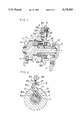
- FIG. 1 is a sectional view of a principal portion of an accelerating system in one embodiment of the present invention
- FIG. 2 is a section taken on line II--II of FIG. 1,
- FIG. 3 is a view partly in section of an entire reel
- FIGS. 4 through 8 are sectional views showing accelerating systems in different embodiments
- FIG. 9 is a sectional view of a principal portion of a decelerating system in one embodiment
- FIG. 10 is a section taken on line A--A of FIG. 9,
- FIG. 11 is a section taken on line B--B of FIG. 9, and
- FIG. 12 is a sectional view of a decelerating system in another embodiment.
- FIGS. 1 through 8 show embodiments that effect acceleration in a directly coupled state.
- a reel body 1 comprises side frames 1a and 1b opposed to each other in a spaced relationship, and a spool 3 rotatably supported by the reel body 1 through a spool shaft 2.
- a tubular input shaft 5 rotatable by operating a handle 4 extends parallel to the spool shaft 2 and includes a first sun gear 6 formed integral with one end thereof.
- the input shaft 5 has an output shaft 7 rotatably fitted therein and rotatably supported at an end by the side frame 1a.
- the output shaft 7 carries a second sun gear 9 formed integral with an intermediate position and having a smaller number of teeth than the first sun gear 6.
- the input shaft 5 carries a gear holder 10 relatively rotatably mounted thereon and rotatably supporting, through a pivotal shaft 12, a differential gear 11 defining toothed portions 11a and 11b having different numbers of teeth for meshing with the first sun gear 6 and second sun gear 9.
- a transmission switching mechanism 8 is formed for selecting between a first transmission line in which rotation of the gear holder 10 is restricted and transmitting drive with acceleration from the input shaft 5 through the differential gear 11 to the output shaft 7, and a second transmission line in which the gear holder 10 is released to be rotatable and directly coupling the input shaft 5 to the output shaft 7.
- the transmission switching mechanism 8 includes a restricting mechanism 81 for restricting or freeing rotation of the gear holder 10, and a one-way rotation transmitting mechanism 82 for providing the second transmission line.
- the rotation of the gear holder 10 is restricted by the restricting mechanism 81 to rotate the differential gear 11, thereby transmitting the rotation of the input shaft 5 with acceleration to the output shaft 7.
- the gear holder 10 is freed from the restriction by the restricting mechanism 81, the differential gear 11 becomes rotatable with the gear holder 10, and the output shaft 7 is directly coupled to the input shaft 5 through the one-way rotation transmitting mechanism 82.
- the restricting mechanism 81 is disposed between the gear holder 10 and side frame 1a, and includes ratchet teeth 81a formed peripherally of the gear holder 10, a restricting pawl 81b engageable with the ratchet teeth 81a to restrict rotation of the gear holder 10 in a direction to wind up a fishing line, and a control element 81c for controlling the restricting pawl 81b from outside the side frame 1a.
- the restricting pawl 81b and control element 81c are supported by the side frame 1a.
- a spring 81d is mounted between the restricting pawl 81b and side frame 1a for urging the restricting pawl 81b toward the ratchet teeth 81a.
- the control element 81c is rotatable counterclockwise in FIG. 2 to disengage the restricting pawl 81b from the ratchet teeth 81a, thereby rendering the gear holder 10 rotatable.
- the input shaft 5 and output shaft 7 are directly coupled to each other through the one-way rotation transmitting mechanism 82.
- the control element 81c is turned clockwise to engage one of the ratchet teeth 81a as shown in FIG. 2, the gear holder 10 is locked against rotation.
- the differential gear 11 is rotatable to transmit rotation of the input shaft 5 with acceleration to the output shaft 7.
- the one-way rotation transmitting mechanism 82 is provided between the input shaft 5 and output shaft 7, and includes ratchet teeth 82a defined on an inside periphery of the input shaft 5 and transmission pawls 82b engageable with the ratchet teeth 82a.
- the transmission pawls 82b are carried by the output shaft 7 to be raisable and retractable, and urged by pawl springs (not shown) toward the ratchet teeth 82a.
- the output shaft 7 includes, as integral parts thereof, a main gear 14, and a backward rotation stopper gear 15 for preventing rotation of the main gear 14 in a direction opposite to the line winding direction.
- the output shaft 7 is rotatably supported at one end thereof by the side frame 1a.
- numeral 16 denotes a pinion gear mounted on the spool shaft 2 and meshed with the main gear 14.
- Numeral 17 denotes a backward rotation stopper pawl engageable with the backward rotation stopper gear 15.
- Numeral 18 denotes a retainer nut for mounting the handle 4 to the input shaft 5.
- Numeral 19 denotes an element for keeping the retainer nut 18 tight.
- the transmission switching mechanism 8 is operated to select the first transmission line. That is, the control element 81c is operated to engage the restricting pawl 81b of the restricting mechanism 81 with one of the ratchet teeth 81a of the gear holder 10 through the spring 81d. This engagement restricts rotation of the gear holder 10.
- the handle 4 attached to an end of the input shaft 5 is turned in the line winding direction, the input shaft 5 is turned with the handle 4, and the differential gear 11 is rotated through the first sun gear 6 of the input shaft 5.
- the output shaft 7 is rotated with acceleration relative to the rotation of the input shaft 5 to an extent corresponding to the difference in the number of teeth between the toothed portions 11a and 11b of the differential gear 11.
- the one-way rotation transmitting mechanism 82 provided in the second transmission line for directly coupling the input shaft 5 and output shaft 7 is placed in an inoperative state by the accelerated rotation of the output shaft 7.
- the output shaft 7 drives the spool 3 at high speed through the main gear 14, pinion gear 16 and spool shaft 2.
- the transmission switching mechanism 8 is operated to select the second transmission line. That is, the control element 81c is operated to disengage the restricting pawl 81b from the ratchet teeth 81a. This disengagement renders the gear holder 10 freely rotatable.
- the handle 4 is turned in the line winding direction, the differential gear 11 supported by the gear holder 10 rotates with the gear holder 10 round the first sun gear 6 and gives no transmission to the output shaft 7.
- the input shaft 5 rotating with the handle 4 is directly coupled to the output shaft 7 through the one-way rotation transmitting mechanism 82, thereby rotating the output shaft 7 without acceleration.
- the output shaft 7 drives the spool 3 through the main gear 14, pinion gear 16 and spool shaft 2, at the same speed as the rotation of the input shaft 5.
- FIG. 4 shows a second embodiment in which the main gear 14 is formed separately from the output shaft 7 as distinct from the first embodiment in which the two elements are formed integral.
- the main gear 14 is rotatably supported on the output shaft 7, and a drag braking mechanism is provided between the main gear and output shaft 7 which includes a drag braking plate 20 for applying a braking force to the rotation of the main gear 14.
- a stationary shaft 21 is inserted into the output shaft 7, which has a collar 21a opposed to a side face of the backward rotation stopper gear 15.
- the stationary shaft 21 is attached at one end thereof to the side frame 1a, and carries a drag adjuster 22 at the other end.
- the output shaft 7 is axially movable by turning the drag adjuster 22, to press the drag braking plate 20 to apply a predetermined resistance and braking force to the rotation of the main gear 14.
- Numeral 23 in FIG. 4 denotes a plate spring.
- FIGS. 5 and 6 show a third embodiment in which the input shaft 5 comprises a solid and stepped shaft, and the output shaft 7 comprises a sleeve shaft.
- the output shaft 7 is rotatably supported on one end portion of the input shaft 5.
- the one-way rotation transmitting mechanism 82 is provided between an inner periphery of the output shaft 7 and an outer periphery of the input shaft 5, that is at an output side of the differential gear 11.
- the direction of the ratchet teeth 82a and transmission pawls 82b of the one-way rotation transmitting mechanism 82 in this embodiment is opposite to that in the embodiments shown in FIGS. 1 through 4.
- the restricting pawl 81b of the restricting mechanism 81 engages one of the ratchet teeth 81a of the gear holder 10 to restrict rotation of the gear holder 10 (the first transmission line is selected).
- the output shaft 7 is rotated clockwise in FIG. 6 with acceleration relative to the input shaft 5. Therefore, where the transmission pawls 82b are attached to the input shaft 5 disposed inside and the ratchet teeth 82a are defined on the output shaft 7 disposed outside, the ratchet teeth 82a and transmission pawls 82b are directed opposite as noted above.
- the other constructional features and functions are the same as in the first embodiment shown in FIGS. 1 through 3, and will not be described again.
- FIGS. 7 and 8 show a fourth embodiment in which a tubular input shaft 5 is rotatably supported by the side frame 1a and a handle shaft 24 is mounted in the tubular input shaft 5 to be relatively slidable but not relatively rotatable.
- the drag adjuster 22 is screwed to one end of the handle shaft 24, with a plate spring 23 mounted between the adjuster 22 and an end face of the input shaft 5.
- the output shaft 7 includes a first shaft 7a having the second sun gear 9 and an outwardly facing collar 7c, and a second shaft 7b carrying the drag braking plate 20 and integrally defining the backward rotation stopper gear 15.
- the first shaft 7a is mounted on the second shaft 7b to be relatively slidable but not relatively rotatable.
- the second shaft 7b is supported on the handle shaft 24 to be relatively rotatable and slidable.
- the one-way rotation transmitting mechanism 82 is provided between the second shaft 7b and handle shaft 24.
- the handle shaft 24 is directly connectable to the second shaft 7 b, that is the second shaft 7b is directly connectable to the input shaft 5, through the one-way rotation transmitting mechanism 82.
- a thrust bearing 25 is mounted between an end face of the input shaft 5 and a stepped inside periphery of the first shaft 7a.
- a further thrust bearing 27 is mounted between an end face of the second shaft 7b and a bearing sleeve 26 attached to the side frame 1a.
- the restricting pawl 81b of the restricting mechanism 81 engages one of the ratchet teeth 81a of the gear holder 10 to restrict rotation of the gear holder 10. That is, when the first transmission line is selected and the handle 4 is turned in the line winding direction, the input shaft 5 is rotated through the handle shaft 24. Then, the differential gear 11 is rotated through the first sun gear 6 of the input shaft 5. The output shaft 7 including the first shaft 7a and second shaft 7b is rotated with acceleration to an extent corresponding to the difference in the number of teeth between the toothed portions 11a and 11b of the differential gear 11. The output shaft 7 is smoothly rotated since the thrust bearing 25 is provided between the input shaft 5 and first shaft 7a.
- the gear holder 10 is supported on the input shaft 5.
- the gear holder 10 may be rotatably supported on the side frame 1a.
- the restricting mechanism 81 has been described as including the ratchet teeth 81a, restricting pawl 81b and control element 81c. However, this construction is not limitative.
- the one-way rotation transmitting mechanism 82 has been described as including the ratchet teeth 82a and transmission pawls 82b. This construction is not limitative, and the mechanism may comprise a cam surface and a roller, for example.
- FIGS. 9 through 12 show embodiments that effect deceleration in a directly coupled state.
- the input shaft 5 rotatable by operating the handle 4 is rotatably supported by the side frame 1a and includes a first sun gear 60 formed integral with one end thereof.
- the input shaft 5 has the output shaft 7 rotatably fitted therein and carries a second sun gear 90 formed integral with an intermediate position and having a larger number of teeth than the first sun gear 60.
- the input shaft 5 carries a gear holder 10 relatively rotatably mounted thereon and rotatably supporting, through a pivotal shaft 12, a differential gear 110 defining toothed portions 110a and 110b having different numbers of teeth for meshing with the first sun gear 60 and second sun gear 90.
- a transmission switching mechanism 80 is formed for selecting between a first transmission line in which rotation of the gear holder 10 is restricted and transmitting drive with deceleration from the input shaft 5 through the differential gear 110 to the output shaft 7, and a second transmission line in which the gear holder 10 is restricted to be rotatable and directly coupling the input shaft 5 to the output shaft 7.
- the transmission switching mechanism 80 includes a stopper mechanism 801 for restricting rotation of the gear holder 10 when the first transmission line is selected by the transmission switching mechanism 80, and a direct coupling mechanism 802 for directly coupling the input shaft 5 and output shaft 7 when the second transmission line is selected.
- the stopper mechanism 801 includes ratchet teeth 801a formed peripherally of the gear holder 10, and a restricting pawl 801b engageable with the ratchet teeth 801a.
- the stopper pawl 801b is pivoted to the side frame 1a, and the gear holder 10 is rotatable in the line winding direction, only rotation in the opposite direction being restricted.
- the differential gear 110 is rotated to transmit rotation of the input shaft 5 to the output shaft 7 with deceleration.
- a spring 801c is mounted between the stopper pawl 801b and side frame 1a for urging the stopper pawl 801b toward the ratchet teeth 801a.
- the direct coupling mechanism 802 includes a ratchet gear 802a attached to an end of the output shaft 7, a transmission pawl 802b engageable with the ratchet gear 802a, and a control element 802c for controlling the transmission pawl 802b.
- the transmission pawl 802b is pivoted to the handle 4 and urged by a pawl spring 802d toward the ratchet gear 802a.
- the control element 802c is movably supported by a cover 28 attached to the handle 4, and is operable to directly couple and decouple the output shaft 7 to the input shaft 5 in the line winding direction.
- the output shaft 7 includes, formed integral with an end thereof, a main gear 14, and a backward rotation stopper gear 15.
- the transmission switching mechanism 80 is operated to select the first transmission line. That is, the control element 802c is operated to disengage the transmission pawl 802b from the ratchet teeth 802a of the direct coupling mechanism 802. This disengagement renders the output shaft 7 rotatable relative to the input shaft 5.
- the handle 4 attached to an end of the input shaft 5 is turned in the line winding direction. Then the input shaft 5 is turned with the handle 4, and the differential gear 110 is rotated through the first sun gear 6 of the input shaft 5.
- the output shaft 7 is rotated with deceleration relative to the input shaft 5 to an extent corresponding to the difference in the number of teeth between the toothed portions 110a and 110b of the differential gear 110.
- the differential gear 110 while rotating, tends to revolve in the direction opposite to the rotation of the input shaft 5.
- the stopper pawl 801b engages the gear holder 10 supporting the differential gear 110, thereby restricting rotation of the gear holder 10 in the direction opposite to the line winding direction.
- the differential gear 110 therefore does not revolve.
- the rotation of the output shaft 7 is decelerated to drive the spool 3 at low speed.
- the transmission switching mechanism 8 For driving the spool 3 at the same speed by directly coupling the input shaft 5 and output shaft 7, the transmission switching mechanism 8 is operated to select the second transmission line. That is, the control element 802c is operated to engage the transmission pawl 802b with one of the ratchet teeth 802a. This engagement directly connects the output shaft 7 to the handle 4. In this state, the output shaft 7 is rotatable without deceleration. Turning of the handle 4 is directly transmitted to the input shaft 5, and through the transmission pawl 802b and ratchet gear 802a to the output shaft 7. Consequently, the gear holder 10 supporting the differential gear 110 rotates with the input shaft 5 and output shaft 7 in the line winding direction, with the differential gear 110 remaining out of rotation. As a result, the output shaft 7 drives the spool 3 through the main gear 14, pinion gear 16 and spool shaft 2, at the same speed as the rotation of the input shaft 5.
- FIG. 12 shows a sixth embodiment which employs a decelerating system opposed to the accelerating system described with reference to FIG. 7.
- a tubular input shaft 5 is rotatably supported by the side frame 1a and a handle shaft 24 is mounted in the tubular input shaft 5 to be relatively slidable but not relatively rotatable.
- the drag adjuster 22 is screwed to one end of the handle shaft 24, with a plate spring 23 mounted between the adjuster 22 and an end face of the input shaft 5.
- the output shaft 7 includes a first shaft 7a having a second sun gear 90 and an outwardly facing collar 7c, and a second shaft 7b carrying the drag braking plate 20 and integrally defining the backward rotation stopper gear 15.
- the first shaft 7a is mounted on the second shaft 7b to be relatively slidable but not relatively rotatable.
- the second shaft 7b is supported on the handle shaft 24 to be relatively rotatable and slidable.
- the transmission switching mechanism 80 has a direct coupling mechanism 802 including engaging recesses 802e, engaging projections 802f, and a control rod 802g inserted axially of the handle shaft 24 to be relatively slidable.
- a thrust bearing 25 is mounted between an end face of the input shaft 5 and a stepped inside periphery of the first shaft 7a.
- a further thrust bearing 27 is mounted between an end face of the second shaft 7b and a bearing sleeve 26 attached to the side frame 1a.
- a slot 24a extends radially of an intermediate position of the handle shaft 24 for movable receiving the engaging projections 802f.
- the handle 4 carries a rotation stopper 19 movably supporting a lever 29.
- the lever 29 defines a slot 29a for receiving the control rod 2g, and the slot 29a is engageable at one end thereof with an engaging member 802h provided on the control rod 802g to maintain the control rod 802g in a control position.
- Numeral 30 denotes a return spring for acting on the control rod 802g.
- the transmission switching mechanism 80 when the transmission switching mechanism 80 is operated to select the first transmission line, i.e. the engaging projections 802f of the direct coupling mechanism 802 are disengaged from the engaging recesses 802e and the handle 4 is turned in the line winding direction, the input shaft 5 is rotated through the handle shaft 24. Then, the differential gear 110 meshed with the first sun gear 6 of the input shaft 5 is rotated. The output shaft 7 including the first shaft 7a and second shaft 7b is rotated with deceleration to an extent corresponding to the difference in the number of teeth between the toothed portions 110a and 110b of the differential gear 110. At this time, the differential gear 110, while rotating, tends to revolve in the direction opposite to the rotation of the input shaft 5.
- the stopper pawl 801b engages the gear holder 10 supporting the differential gear 110, thereby restricting rotation of the gear holder 10 in the direction opposite to the line winding direction.
- the differential gear 110 therefore does not revolve.
- the rotation of the output shaft 7 is decelerated to drive the spool 3 at low speed.
- the output shaft 7 is smoothly rotated since the thrust bearing 25 is provided between the input shaft 5 and second shaft 7b.
- the output shaft 7 drives the spool 3 through the main gear 14, pinion gear 16 and spool shaft 2, at the same speed as the rotation of the input shaft 5.
- the drag braking plate 20 is pressed against the handle shaft 24 through the input shaft 5, thrust bearing 25 and first shaft 7a, to apply a resistance to the rotation of the main gear 14.
- the gear holder 10 may be rotatably supported on the side frame 1a.
- the stopper mechanism 801 and direct coupling mechanism 802 of the transmission switching mechanism 80 are not limited to the described constructions.
- a plurality of differential gears 11 may be provided instead of one.
- the change speed apparatus is used with a two-bearing reel for taking up the fishing line on the spool 3 as described.
- this apparatus may be applied to a spinning reel constructed to take up a fishing line on a spool by driving a rotatable frame.
Landscapes
- Engineering & Computer Science (AREA)
- General Engineering & Computer Science (AREA)
- Mechanical Engineering (AREA)
Applications Claiming Priority (2)
| Application Number | Priority Date | Filing Date | Title |
|---|---|---|---|
| JP2010983A JP2839104B2 (ja) | 1990-01-20 | 1990-01-20 | 釣用リールの変速装置 |
| JP2-10983 | 1990-01-20 |
Publications (1)
| Publication Number | Publication Date |
|---|---|
| US5178343A true US5178343A (en) | 1993-01-12 |
Family
ID=11765387
Family Applications (1)
| Application Number | Title | Priority Date | Filing Date |
|---|---|---|---|
| US07/642,784 Expired - Fee Related US5178343A (en) | 1990-01-20 | 1991-01-18 | Change speed apparatus for a fishing reel |
Country Status (3)
| Country | Link |
|---|---|
| US (1) | US5178343A (ja) |
| JP (1) | JP2839104B2 (ja) |
| GB (1) | GB2241292B (ja) |
Cited By (5)
| Publication number | Priority date | Publication date | Assignee | Title |
|---|---|---|---|---|
| US5372323A (en) * | 1992-01-30 | 1994-12-13 | Daiwa Seiko, Inc. | Fishing reel with one-way brake mechanism |
| US5379959A (en) * | 1992-09-11 | 1995-01-10 | Shimano Inc. | Fishing reel having one-way brake |
| US6007012A (en) * | 1997-01-08 | 1999-12-28 | Daiwa Seiko, Inc. | Fishing reel having a reversal preventative mechanism |
| US20030146322A1 (en) * | 2002-02-04 | 2003-08-07 | Shimano, Inc. | Fishing-reel power transmission device |
| US9307749B1 (en) * | 2012-05-16 | 2016-04-12 | Harout Alajajyan | Fishing reel speed control |
Families Citing this family (10)
| Publication number | Priority date | Publication date | Assignee | Title |
|---|---|---|---|---|
| US6446894B1 (en) | 2000-05-11 | 2002-09-10 | Pure Fishing, Inc. | Planetary gear assembly for fishing reel |
| JP3622202B2 (ja) | 2001-08-29 | 2005-02-23 | セイコーエプソン株式会社 | 弾性表面波装置の温度特性調整方法 |
| JP2011067171A (ja) * | 2009-09-28 | 2011-04-07 | Globeride Inc | 魚釣用リール |
| JP2012060422A (ja) | 2010-09-09 | 2012-03-22 | Seiko Epson Corp | 弾性表面波デバイス、電子機器及びセンサー装置 |
| JP2012060421A (ja) | 2010-09-09 | 2012-03-22 | Seiko Epson Corp | 弾性表面波デバイス、電子機器及びセンサー装置 |
| JP2012060418A (ja) | 2010-09-09 | 2012-03-22 | Seiko Epson Corp | 弾性表面波デバイス、電子機器及びセンサー装置 |
| JP2012060420A (ja) | 2010-09-09 | 2012-03-22 | Seiko Epson Corp | 弾性表面波デバイス、電子機器及びセンサー装置 |
| JP2012060419A (ja) | 2010-09-09 | 2012-03-22 | Seiko Epson Corp | 弾性表面波デバイス、電子機器及びセンサー装置 |
| CN102959860B (zh) | 2011-04-12 | 2016-03-23 | 天工松下滤波方案日本有限公司 | 弹性波元件和使用它的天线共用器 |
| KR102766001B1 (ko) * | 2018-07-13 | 2025-02-12 | 가부시키가이샤 시마노 | 전동 릴의 감속 장치, 전동 릴의 감속 장치의 제조 방법, 및 낚시용 전동 릴 |
Citations (15)
| Publication number | Priority date | Publication date | Assignee | Title |
|---|---|---|---|---|
| US703614A (en) * | 1901-10-19 | 1902-07-01 | Rollin C Sprague | Car-brake. |
| US2335752A (en) * | 1940-11-13 | 1943-11-30 | Ralph I Geiger | Fishing reel |
| US2417732A (en) * | 1939-02-14 | 1947-03-18 | Bland Reginald | Fishing reel mechanism |
| US2517776A (en) * | 1945-09-17 | 1950-08-08 | Louis B Feierabend | Automatic two-speed fishing reel |
| GB766157A (en) * | 1954-02-03 | 1957-01-16 | Lucas Industries Ltd | A two-speed mechanism |
| GB770420A (en) * | 1954-03-19 | 1957-03-20 | Union Carbide & Carbon Corp | Heterocyclic phosphorus-containing mono-fluorides and process for making same |
| US2918227A (en) * | 1952-11-03 | 1959-12-22 | Mauborgne Paul | Variable drive device for fishing winches |
| US4566655A (en) * | 1984-11-09 | 1986-01-28 | Charles C. Worth Corporation | Two-speed drive for a fishing reel |
| US4867392A (en) * | 1987-04-11 | 1989-09-19 | Shimano Industrial Company Limited | Speed changing device for a fishing reel |
| US4871129A (en) * | 1988-03-25 | 1989-10-03 | Daiwa Seiko Inc. | Speed change of fishing reel |
| JPH01277441A (ja) * | 1988-04-28 | 1989-11-07 | Daiwa Seiko Inc | 魚釣用リールの変速装置 |
| US4927095A (en) * | 1989-01-23 | 1990-05-22 | Charles C. Worth Corporation | Planetary gear drive for fishing reel |
| US4951899A (en) * | 1989-06-20 | 1990-08-28 | Abu Garcia Produktion Ab | Dual-type gear unit for a multiplier reel |
| US4966335A (en) * | 1988-05-13 | 1990-10-30 | Daiwa Seiko Inc. | Speed changer for fishing reels |
| US5110066A (en) * | 1990-04-06 | 1992-05-05 | Shimano Inc. | Speed change apparatus for a fishing reel |
Family Cites Families (1)
| Publication number | Priority date | Publication date | Assignee | Title |
|---|---|---|---|---|
| GB777420A (en) * | 1951-02-06 | 1957-06-19 | Atomic Energy Authority Uk | Improvements in or relating to variable speed gearing |
-
1990
- 1990-01-20 JP JP2010983A patent/JP2839104B2/ja not_active Expired - Fee Related
-
1991
- 1991-01-18 GB GB9101196A patent/GB2241292B/en not_active Expired - Fee Related
- 1991-01-18 US US07/642,784 patent/US5178343A/en not_active Expired - Fee Related
Patent Citations (15)
| Publication number | Priority date | Publication date | Assignee | Title |
|---|---|---|---|---|
| US703614A (en) * | 1901-10-19 | 1902-07-01 | Rollin C Sprague | Car-brake. |
| US2417732A (en) * | 1939-02-14 | 1947-03-18 | Bland Reginald | Fishing reel mechanism |
| US2335752A (en) * | 1940-11-13 | 1943-11-30 | Ralph I Geiger | Fishing reel |
| US2517776A (en) * | 1945-09-17 | 1950-08-08 | Louis B Feierabend | Automatic two-speed fishing reel |
| US2918227A (en) * | 1952-11-03 | 1959-12-22 | Mauborgne Paul | Variable drive device for fishing winches |
| GB766157A (en) * | 1954-02-03 | 1957-01-16 | Lucas Industries Ltd | A two-speed mechanism |
| GB770420A (en) * | 1954-03-19 | 1957-03-20 | Union Carbide & Carbon Corp | Heterocyclic phosphorus-containing mono-fluorides and process for making same |
| US4566655A (en) * | 1984-11-09 | 1986-01-28 | Charles C. Worth Corporation | Two-speed drive for a fishing reel |
| US4867392A (en) * | 1987-04-11 | 1989-09-19 | Shimano Industrial Company Limited | Speed changing device for a fishing reel |
| US4871129A (en) * | 1988-03-25 | 1989-10-03 | Daiwa Seiko Inc. | Speed change of fishing reel |
| JPH01277441A (ja) * | 1988-04-28 | 1989-11-07 | Daiwa Seiko Inc | 魚釣用リールの変速装置 |
| US4966335A (en) * | 1988-05-13 | 1990-10-30 | Daiwa Seiko Inc. | Speed changer for fishing reels |
| US4927095A (en) * | 1989-01-23 | 1990-05-22 | Charles C. Worth Corporation | Planetary gear drive for fishing reel |
| US4951899A (en) * | 1989-06-20 | 1990-08-28 | Abu Garcia Produktion Ab | Dual-type gear unit for a multiplier reel |
| US5110066A (en) * | 1990-04-06 | 1992-05-05 | Shimano Inc. | Speed change apparatus for a fishing reel |
Cited By (6)
| Publication number | Priority date | Publication date | Assignee | Title |
|---|---|---|---|---|
| US5372323A (en) * | 1992-01-30 | 1994-12-13 | Daiwa Seiko, Inc. | Fishing reel with one-way brake mechanism |
| US5379959A (en) * | 1992-09-11 | 1995-01-10 | Shimano Inc. | Fishing reel having one-way brake |
| US6007012A (en) * | 1997-01-08 | 1999-12-28 | Daiwa Seiko, Inc. | Fishing reel having a reversal preventative mechanism |
| US20030146322A1 (en) * | 2002-02-04 | 2003-08-07 | Shimano, Inc. | Fishing-reel power transmission device |
| US6702214B2 (en) * | 2002-02-04 | 2004-03-09 | Shimano, Inc. | Fishing-reel power transmission device |
| US9307749B1 (en) * | 2012-05-16 | 2016-04-12 | Harout Alajajyan | Fishing reel speed control |
Also Published As
| Publication number | Publication date |
|---|---|
| GB9101196D0 (en) | 1991-02-27 |
| GB2241292A (en) | 1991-08-28 |
| JPH03216137A (ja) | 1991-09-24 |
| GB2241292B (en) | 1994-03-16 |
| JP2839104B2 (ja) | 1998-12-16 |
Similar Documents
| Publication | Publication Date | Title |
|---|---|---|
| EP1840024B1 (en) | Bicycle shifter | |
| JP2599596B2 (ja) | 自転車用変速装置 | |
| US7000496B2 (en) | Cable retraction mechanism for trigger shifters | |
| JP2930315B2 (ja) | 自転車用内装変速機 | |
| EP0392457B1 (en) | Speed control apparatus for a bicycle | |
| GB2241292A (en) | Change speed apparatus for a fishing reel | |
| US3828627A (en) | Multiple-speed hub | |
| JP2007501157A (ja) | 自動変速装置 | |
| JP3457688B2 (ja) | 内装変速ハブ | |
| US4871129A (en) | Speed change of fishing reel | |
| US5110066A (en) | Speed change apparatus for a fishing reel | |
| JPH0947198A (ja) | 魚釣用電動リール | |
| US5593102A (en) | Spinning reel for fishing having a mechanism for linking the spool reverse preventive and the drag device | |
| EP1452437B2 (en) | An internal hub transmission for a bicycle | |
| US3113652A (en) | Dual speed coaster hub | |
| JP3515905B2 (ja) | 魚釣用電動リール | |
| JPH0650968B2 (ja) | 魚釣用リールの変速装置 | |
| JP2595353B2 (ja) | ドラグ機構付きリール | |
| EP0669551B1 (en) | Apparatus and method for driving a takeup spool using a clutch mechanism | |
| JP2001148977A (ja) | 魚釣用電動リール | |
| JP3978007B2 (ja) | 魚釣用リール | |
| JP3895619B2 (ja) | 魚釣用リール | |
| JP2001095445A (ja) | 魚釣用電動リール | |
| JPH04308440A (ja) | ギヤードモータ | |
| JP2003284474A (ja) | 魚釣用電動リール |
Legal Events
| Date | Code | Title | Description |
|---|---|---|---|
| AS | Assignment |
Owner name: SHIMANO INDUSTRIAL CO., LTD., 77, OIMATSUCHO 3 CHO Free format text: ASSIGNMENT OF ASSIGNORS INTEREST.;ASSIGNOR:SATO, JUN;REEL/FRAME:005649/0140 Effective date: 19910306 |
|
| FEPP | Fee payment procedure |
Free format text: PAYOR NUMBER ASSIGNED (ORIGINAL EVENT CODE: ASPN); ENTITY STATUS OF PATENT OWNER: LARGE ENTITY |
|
| FPAY | Fee payment |
Year of fee payment: 4 |
|
| FPAY | Fee payment |
Year of fee payment: 8 |
|
| REMI | Maintenance fee reminder mailed | ||
| LAPS | Lapse for failure to pay maintenance fees | ||
| STCH | Information on status: patent discontinuation |
Free format text: PATENT EXPIRED DUE TO NONPAYMENT OF MAINTENANCE FEES UNDER 37 CFR 1.362 |
|
| FP | Lapsed due to failure to pay maintenance fee |
Effective date: 20050112 |