US5228246A - Apparatus for turning up an down seats for telescopic seating system - Google Patents
Apparatus for turning up an down seats for telescopic seating system Download PDFInfo
- Publication number
- US5228246A US5228246A US07/687,392 US68739291A US5228246A US 5228246 A US5228246 A US 5228246A US 68739291 A US68739291 A US 68739291A US 5228246 A US5228246 A US 5228246A
- Authority
- US
- United States
- Prior art keywords
- foot
- guide arm
- center shaft
- shaft
- movable platform
- Prior art date
- Legal status (The legal status is an assumption and is not a legal conclusion. Google has not performed a legal analysis and makes no representation as to the accuracy of the status listed.)
- Expired - Lifetime
Links
Images

Classifications
-
- E—FIXED CONSTRUCTIONS
- E04—BUILDING
- E04H—BUILDINGS OR LIKE STRUCTURES FOR PARTICULAR PURPOSES; SWIMMING OR SPLASH BATHS OR POOLS; MASTS; FENCING; TENTS OR CANOPIES, IN GENERAL
- E04H3/00—Buildings or groups of buildings for public or similar purposes; Institutions, e.g. infirmaries or prisons
- E04H3/10—Buildings or groups of buildings for public or similar purposes; Institutions, e.g. infirmaries or prisons for meetings, entertainments, or sports
- E04H3/12—Tribunes, grandstands or terraces for spectators
- E04H3/123—Telescopic grandstands
-
- A—HUMAN NECESSITIES
- A47—FURNITURE; DOMESTIC ARTICLES OR APPLIANCES; COFFEE MILLS; SPICE MILLS; SUCTION CLEANERS IN GENERAL
- A47C—CHAIRS; SOFAS; BEDS
- A47C1/00—Chairs adapted for special purposes
- A47C1/12—Theatre, auditorium or similar chairs
- A47C1/126—Theatre, auditorium or similar chairs stowable in floor or wall
Definitions
- the present invention relates generally to an apparatus for turning up and down a number of seats for a telescopic seating system. More particularly, the present invention relates to an apparatus for turning up spectators' seats to assume the upright standing attitude before using the telescopic seating system and turning down them to assume the horizontally laid attitude after completion of the practical use of the same.
- a telescopic seating system including a plurality of extensive/contractive movable platforms arranged in tiers is increasingly employed for a building such as a gymnasium or the like facility in order to utilize the floor space more effectively by fully accommodating all the movable platforms in a cavity formed in the one side wall structure of the building when the telescopic seating system is not in use.
- the movable platforms used for the telescopic seating system are arranged in the form of a so-called doll tier stand such that the foremost movable platform is located at the lowermost position and the rearmost movable platform is located at the highest position when the telescopic seating system is practically used while all the movable platforms assume their extended attitude.
- An object of the present invention is to provide an apparatus for turning up and down a number of seats for a telescopic seating system which is entirely free from the problems inherent to the conventional telescopic seating system.
- Another object of the present invention is to provide an apparatus for turning up and down a number of seats for a telescopic seating system wherein each seat on each movable platform is easily turned up with the aid of a sum of the resilient forces derived from a plurality of coil springs without necessity for an extra power to be generated by an electric motor or the like means.
- Another object of the present invention is to provide an apparatus for turning up and down a number of seats for a telescopic seating system wherein all the seats arranged on each movable platform side by side in the transverse direction can simultaneously smoothly be turned down by utilizing successive rearward movement of the movable platforms when the telescopic seating system is not put in practical use.
- the present invention provides an apparatus for turning up and down seats for a telescopic seating system including a plurality of movable platforms to be arranged in tiers when the telescopic seating system is in use, the movable platforms being successively operatively connected to each other to extend and contract in the forward/rearward direction, the respective seats being arranged side by side in the transverse direction on each movable platform, wherein the apparatus includes as essential components a foot on which a single seat is fixedly mounted, the foot being turned up and down about a support shaft, a housing in the form of a base frame having a substantially U-shaped cross-sectional configuration, the housing having the support shaft for the foot immovably inserted therethrough in the transverse direction at the fore end part thereof, a center shaft rotatably inserted through the housing in the transverse direction at the central part of the housing, the center shaft extending in parallel with the support shaft and including an extension outside of the outer side wall of the housing, a guide arm turnably mounted on the extension
- the movable platform at the lower stage is displaced in the rearward direction and thereby the guide arm which has been brought in contact with the rear surface of the front transverse beam at the present stage collides against the rear transverse beam of the movable platform at the lower stage, whereby the rearward turning movement of the guide arm is transmitted to the foot which has stood upright, via the center shaft, the tongue-shaped projections and the link plate so as to allow the foot to be turned down.
- the apparatus further includes a rotary member which is fixedly mounted on the extension of the center shaft outside of the guide arm such that an opposing pair of stoppers are protruded toward the guide arm in the axial direction of the center shaft.
- a rotary member which is fixedly mounted on the extension of the center shaft outside of the guide arm such that an opposing pair of stoppers are protruded toward the guide arm in the axial direction of the center shaft.
- One of the stoppers located in front of the center shaft is to be brought in contact with the front surface of the guide arm so as to limit the forward turning movement of the guide arm, while the other stopper located behind the center shaft is to be brought in contact with the rear surface of the guide arm so as to allow the rearward turning movement of the guide arm to be transmitted to the foot via this stopper, the rotary member, the center shaft, the tongue-shaped projections and the link plate.
- the apparatus further includes a third coil spring which is mounted on the extension of the center shaft between the guide arm and the rotary member.
- One end of the third coil spring is fixedly secured to the guide arm, while the other end of the same is fixedly secured to the rotary member so as to allow the guide arm to be normally turnably biased in the forward direction in addition to the second coil spring.
- the guide arm collides against the front transverse beam of the movable platform at the present stage at an intermediate position which is located slightly before the upright standing position. Thereafter, the foot continues to be turnably raised up until the upright standing position is reached, merely with the aid of the resilient force derived from the first coil springs.
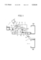
- FIG. 1 is a side view of an apparatus for turning up and down a number of seats for a telescopic seating system in accordance with an embodiment of the present invention, particularly illustrating that a foot starts turning-up movement in response to forward movement of a movable platform at a certain stage;
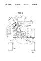
- FIG. 2 is a side view of the apparatus shown in FIG. 1, particularly illustrating that the foot starts turning-down movement in response to rearward movement of the movable platform;
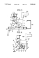
- FIG. 3 is a fragmentary side view of the apparatus, particularly illustrating that the foot assumes an intermediate position (represented by two-dot chain lines) slightly before the upright standing position as well as the upright standing position (represented by solid lines) by forward turning movement of a guide arm with the aid of a resilient force derived from a plurality of coil springs;
- FIG. 4 is a fragmentary side view of the apparatus, particularly illustrating the operational relationship between a link plate and a pair of tongue-shaped projections when the foot is fully raised up to assume the upright standing position;
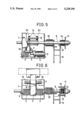
- FIG. 5 is a sectional plan view of the apparatus taken along line IV 1 --IV 1 and line IV 2 --IV 2 in FIG. 4;
- FIG. 6 is a front view of the apparatus as seen in the operative state in FIG. 4;
- FIG. 7 is a partially sectioned side view of the telescopic seating system for which a number of apparatuses of the present invention are employed.
- FIG. 7 is a fragmentary side view of the telescopic seating system 100.
- the whole telescopic seating system 100 is forwardly displaced along a floor surface 109.
- a plurality of movable platforms 104 having a number of spectators seats 108 mounted side by side in the transverse direction thereon are successively drawn from the lower stage side in the forward direction together with base boards 101 and support columns 103 fixedly secured to the movable platforms 104 with the aid of a number of rollers 102 which are driven by an actuating mechanism (not shown).
- the telescopic seating system On completion of the slidable movement of the movable platform 104 in the forward direction, the telescopic seating system exhibits the fully extended state and all the platforms 104 are arranged in tiers, as shown in FIG. 7.
- Each movable platform 104 to be arranged in tiers in the operative state includes a plurality of seats 108 in the side-by-side relationship each of which is allocated to one of plural blocks equally spaced along the transversely extending movable platform 104.
- FIG. 7 the apparatus in accordance with the embodiment of the present invention designated by reference numeral 107 in FIG. 7 will be described below with reference to FIG. 1 to FIG. 6.
- two apparatuses 107 are arranged on the both sides of each spectator's seat 108.
- description will be made below as to one of the two apparatuses 17 for the purpose of simplification of description, because all components constituting each of the left-hand and right-hand apparatuses are same to each other with the exception that they are arranged in the symmetrically relationship.
- the apparatus 107 is basically composed of a base frame 1, a support shaft 2, a foot 3, a pair of coil spring 4 each adapted to normally turn the foot 3 in the clockwise direction as seen in FIG. 2 by the resilient force derived therefrom, a center shaft 5, a pair of link plates 6, a guide arm 9, a coil spring 10 adapted to normally turn the guide arm 9 in the clockwise direction as seen in FIG. 1 by the resilient force derived therefrom, a turn plate 11, stoppers 12 and 13 and a coil spring 14 adapted to normally turn the guide arm 9 by the resilient force derived therefrom.
- the base frame 1 is designed in the substantially U-shaped cross-sectional configuration of which front side is opened to the outside.
- the foot 3 is designed in the substantially square cross-sectional configuration and includes a foot member 31 and a transverse member having the substantially L-shaped cross-sectional configuration so as to allow a spectator's seat 108 to be fixedly mounted thereon (see FIG. 2).
- the foot 3 is turnably supported by the support shaft 2 extending through the base end part thereof in the transverse direction to turn about the support shaft 2 in the clockwise/anticlockwise direction.
- the pair of coils springs 4 each having a large magnitude of resilient force are mounted on the support shaft 2 such that one end of each of the coil springs 4 is fixedly secured to the base frame 1 and the other end of the same is fixedly secured to the foot 3, whereby the foot 3 is normally biased in the raising-up direction by the resilient force derived from the coil springs 4.
- a front transverse shaft 7 is inserted through the foot 3 at the intermediate position of the same while extending in parallel with the support shaft 2.
- the foot member 31 constituting the lower end part of the spectator's seat 108 is fixedly attached to the foot 3 such that the spectator's seat 108 is turned in the raising-up/lowering direction together with the foot 3.
- the center shaft 5 is located behind the support shaft 2 while extending through the base frame 1 in the transverse direction of the spectator's seat 108. It is obvious that the center shaft 5 is inserted through the opposite base frame 1 (not shown) in the same manner.
- a pair of tongue-shaped projections 51 are integrated with a larger diameter portion of the center shaft 5 within the hollow space of the base frame 1 to turn about the center shaft 5 together with the same (see FIG. 4 and FIG. 5). It should be noted that the tongue-shaped projections 51 rearwardly extend in the slantwise downward direction when the foot 3 stands upright.
- the front transverse shaft 7 is inserted through the pair of link plates 6 in parallel with the center shaft 5 and a rear transverse shaft 8 is inserted through the pair of tongue-shaped projections 51 in parallel with the center shaft 5, whereby the foot 3 is operatively connected to the projections 51 via the link plates 6, the fore transverse shaft 7 and the rear transverse shaft 8.
- the center shaft 5 has an extension outside of the one side wall of the base frame 1, and the base end of the guide arm 9 is rotatably mounted on the extension of the center shaft 5.
- the coil spring 10 adapted to normally bias the foot 3 in the raising-up direction by the resilient force derived therefrom is mounted on the extension of the center shaft 5 between the base frame 1 and the guide arm 9 such that one end of the coil spring 10 is fixedly secured to the base frame 1 and the other end of the same is fixedly secured to the guide arm 9. While any outer force is not exerted on the guide arm 9, the fore end part of the guide arm 9 is turnably displaced in the forward direction by the resilient force of the coil spring 10.
- the guide arm 9 when an outer force is exerted on the guide arm 9 from the front side, the guide arm 9 is turnably displaced in the rearward direction.
- the guide arm 9 is dimensioned to have a length enough to turn within the range where a transverse beam 6 of the movable platform 104 at the lower stage moves in the forward/rearward direction (see FIG. 1 and FIG. 2).
- a circular rotary member 11 is fixedly mounted on the extension of the center shaft 5 at the outermost end of the same in the coaxial relationship, and a pair of stoppers 12 and 13 are projected inside of the rotary member 11 (extending toward the base frame 1) in the spaced relationship such that one of them, i.e. the stopper 12 comes in contact with the front surface of the guide arm 9 and the other one, i.e., the stopper 13 comes in the rear surface of the guide arm 9.
- the both stoppers 12 and 13 may be integrated with the rotary member 11 by employing a casting process.
- the coil spring 14 adapted to normally bias the guide arm 9 in the clockwise direction by the resilient force derived therefrom is mounted on the extension of the center shaft 5 between the guide arm 9 and the rotary member 11.
- the apparatus 107 of the present invention is constituted by the aforementioned components to provide a single assembly.
- the apparatus 107 serves as a base portion of each spectator's seat 108 adjacent to the support column 103.
- a plurality of spectators's seats 108 are arranged side by side relationship in the transverse direction in the spaced relationship on the movable platform 104 at each stage and each spectator's seat 108 is allocated to one of a plurality of blocks along the movable platform 104.
- an operator controls a controller (not shown) such that the movable platforms 104 are successively displaced in the forward direction one after another starting with the lowermost movable platform 104.
- a moving body (not shown) arranged on the bottom side of the movable platform 104 at the lowermost stage starts forward movement.
- the operator control the controller so as to operate the driving unit for the telescopic seating system 100 in the opposite direction, whereby the movable platforms 104 are successively displaced in the rearward direction starting with the lowermost movable platform 104.
- the movable platform 104 at the lower stage (the movable body (not shown) on the bottom side in a case of the movable platform 104 at the lowermost stage) is displaced in the rearward direction
- the foremost end of the guide arm 9 at the present stage is brought in contact with the rear surface of the square steel pipe 110 for the movable platform 104 at the present stage.
- the transverse beams 106 at the lower stage is displaced in the rearward direction
- the foremost end of the guide arm 9 at the present stage is turnably displaced in the rearward direction against the resilient force of the coil spring 10 (see FIG. 2).
- the stopper 13 which has been brought in contact with the rear surface of the guide arm 9 is rotated in the anticlockwise direction as the guide arm 9 is turned.
- This causes the foot 3 which has been fully raised up to be forwardly turned to the intermediate position via the link plates 6 which are operatively connected with the rotary member 11 integrated with the center shaft 5 (see FIG. 2).
- the foremost end of the guide arm 9 continues rearward turning movement of the guide arm 9 and is forcibly placed on the upper surface of the transverse beam 106 for the movable platform 104 at the lower stage, the movable platform 104 at the present stage starts rearward movement.
- an abutment plate 32 fastened to the rear surface of a foot stand 31 collides against a front nose 105 at the foremost end of the movable platform 104 at the upper stage, whereby the foot 3 is increasingly turned down until it assumes the horizontally laid attitude. Consequently, a series of spectators' seats 108 arranged side by side in the transverse direction on the movable platform 104 at the present stage 104 can completely be laid down in the inoperative state on the upper surface of the movable platform 104, as represented by two-dot chain lines in FIG. 2.
- the present invention has been described above as to a case where a number of spectators s seats 108 are arranged in the transverse direction in the equally spaced relationship for the telescopic seating system. Alternatively, the present invention may equally be applied to a single seat with the same advantages as those mentioned above.
- the apparatus of the present invention is provided with a pair of coil springs within the interior of the U-shaped base frame each adapted to normally bias the foot in the raising-up direction and a coil spring mounted on an extension of the center shaft between the base frame and the guide arm to normally bias the guide arm in the direction of forward turning movement.
- the arrangement of the coil springs in that way generates a large magnitude of resilient force effective for raising up the foot and thereby assures that the foot can quickly and reliably stand upright without necessity for an extra power to be derived from an electric motor or the like means when the telescopic seating system is in use. Consequently, a function of the telescopic seating system can be improved substantially at an inexpensive cost of installation with a minimized quantity of consumed electricity.
- the aforementioned springs i.e., essential components for the apparatus of the present invention are arranged in the positionally well-balanced state not only within the interior of the base beam but also outside of the base frame, a magnitude of reactive force against the resilient force derived from the aforementioned coil springs can be reduced when each spectator's seat is laid down to assume the horizontally laid position after completion of the practical use of the telescopic seating system. Therefore, a turning-down operation can be performed for all the spectators' seats with a small magnitude of extra force when the telescopic seating system is not in use.
Landscapes
- Engineering & Computer Science (AREA)
- Architecture (AREA)
- Health & Medical Sciences (AREA)
- Dentistry (AREA)
- General Health & Medical Sciences (AREA)
- Civil Engineering (AREA)
- Structural Engineering (AREA)
- Chairs For Special Purposes, Such As Reclining Chairs (AREA)
Applications Claiming Priority (2)
| Application Number | Priority Date | Filing Date | Title |
|---|---|---|---|
| JP2102551A JPH041371A (ja) | 1990-04-18 | 1990-04-18 | 伸縮式階段状観覧席の椅子自動起立転倒装置 |
| JP2-102551 | 1990-04-18 |
Publications (1)
| Publication Number | Publication Date |
|---|---|
| US5228246A true US5228246A (en) | 1993-07-20 |
Family
ID=14330382
Family Applications (1)
| Application Number | Title | Priority Date | Filing Date |
|---|---|---|---|
| US07/687,392 Expired - Lifetime US5228246A (en) | 1990-04-18 | 1991-04-18 | Apparatus for turning up an down seats for telescopic seating system |
Country Status (4)
| Country | Link |
|---|---|
| US (1) | US5228246A (de) |
| EP (1) | EP0452918B1 (de) |
| JP (1) | JPH041371A (de) |
| DE (1) | DE69101073D1 (de) |
Cited By (5)
| Publication number | Priority date | Publication date | Assignee | Title |
|---|---|---|---|---|
| US5517789A (en) * | 1993-10-22 | 1996-05-21 | Kabushiki Kaisha Kotobuki | Variable floor height telescopic multi-staged spectator seating system |
| DE10152509A1 (de) * | 2001-10-24 | 2003-05-08 | Werner Hansal | Tribünensitzanordnung |
| US6625932B1 (en) | 1998-03-03 | 2003-09-30 | Dexter Littlefield | Variable rise vertically retractable arena seating assembly |
| US20070200409A1 (en) * | 2006-02-28 | 2007-08-30 | Interkal, Llc | Forward folding seat assembly |
| US20110215621A1 (en) * | 2008-11-21 | 2011-09-08 | Laforest Pierre | Removable seats system |
Families Citing this family (3)
| Publication number | Priority date | Publication date | Assignee | Title |
|---|---|---|---|---|
| JP2948516B2 (ja) * | 1995-09-29 | 1999-09-13 | 株式会社コトブキ | 伸縮式階段状観覧席の起立転倒装置 |
| FR2746434B1 (fr) * | 1996-03-20 | 1998-06-19 | Husson Collectivites Sa | Tribune telescopique a manoeuvre automatique |
| JP2009166387A (ja) | 2008-01-17 | 2009-07-30 | Ricoh Co Ltd | 画像形成方法および画像形成記録物 |
Citations (7)
| Publication number | Priority date | Publication date | Assignee | Title |
|---|---|---|---|---|
| US4063392A (en) * | 1977-02-11 | 1977-12-20 | American Seating Company | Telescoping seating system with automatically folding chairs |
| US4155202A (en) * | 1978-04-03 | 1979-05-22 | American Seating Company | Telescoping seating system with automatically folding chairs |
| US4446659A (en) * | 1982-12-20 | 1984-05-08 | American Seating Company | Automatic seating for telescoping row systems |
| US4557080A (en) * | 1984-07-18 | 1985-12-10 | American Seating Company | Automatic seating for telescoping row systems |
| US4569162A (en) * | 1983-11-07 | 1986-02-11 | Kabushiki Kaisha Kotobuki | Apparatus for turning up and down seats for a telescopic seating system |
| US4702043A (en) * | 1986-02-28 | 1987-10-27 | Kabushiki Kaisha Kotobuki | Apparatus for turning up and down seats for a telescopic seating system |
| EP0369094A1 (de) * | 1988-11-18 | 1990-05-23 | Okamura Corporation | Vorrichtung zum Aufrichten der Sitze in jeder Reihe eines ausziehbaren Sitzsystems |
-
1990
- 1990-04-18 JP JP2102551A patent/JPH041371A/ja active Pending
-
1991
- 1991-04-18 EP EP91106209A patent/EP0452918B1/de not_active Expired - Lifetime
- 1991-04-18 US US07/687,392 patent/US5228246A/en not_active Expired - Lifetime
- 1991-04-18 DE DE91106209T patent/DE69101073D1/de not_active Expired - Lifetime
Patent Citations (7)
| Publication number | Priority date | Publication date | Assignee | Title |
|---|---|---|---|---|
| US4063392A (en) * | 1977-02-11 | 1977-12-20 | American Seating Company | Telescoping seating system with automatically folding chairs |
| US4155202A (en) * | 1978-04-03 | 1979-05-22 | American Seating Company | Telescoping seating system with automatically folding chairs |
| US4446659A (en) * | 1982-12-20 | 1984-05-08 | American Seating Company | Automatic seating for telescoping row systems |
| US4569162A (en) * | 1983-11-07 | 1986-02-11 | Kabushiki Kaisha Kotobuki | Apparatus for turning up and down seats for a telescopic seating system |
| US4557080A (en) * | 1984-07-18 | 1985-12-10 | American Seating Company | Automatic seating for telescoping row systems |
| US4702043A (en) * | 1986-02-28 | 1987-10-27 | Kabushiki Kaisha Kotobuki | Apparatus for turning up and down seats for a telescopic seating system |
| EP0369094A1 (de) * | 1988-11-18 | 1990-05-23 | Okamura Corporation | Vorrichtung zum Aufrichten der Sitze in jeder Reihe eines ausziehbaren Sitzsystems |
Cited By (6)
| Publication number | Priority date | Publication date | Assignee | Title |
|---|---|---|---|---|
| US5517789A (en) * | 1993-10-22 | 1996-05-21 | Kabushiki Kaisha Kotobuki | Variable floor height telescopic multi-staged spectator seating system |
| US6625932B1 (en) | 1998-03-03 | 2003-09-30 | Dexter Littlefield | Variable rise vertically retractable arena seating assembly |
| DE10152509A1 (de) * | 2001-10-24 | 2003-05-08 | Werner Hansal | Tribünensitzanordnung |
| US20070200409A1 (en) * | 2006-02-28 | 2007-08-30 | Interkal, Llc | Forward folding seat assembly |
| US20110215621A1 (en) * | 2008-11-21 | 2011-09-08 | Laforest Pierre | Removable seats system |
| US8490335B2 (en) * | 2008-11-21 | 2013-07-23 | Gestion Laforest Inc. | Removable seats system |
Also Published As
| Publication number | Publication date |
|---|---|
| EP0452918A1 (de) | 1991-10-23 |
| EP0452918B1 (de) | 1994-01-26 |
| DE69101073D1 (de) | 1994-03-10 |
| JPH041371A (ja) | 1992-01-06 |
Similar Documents
| Publication | Publication Date | Title |
|---|---|---|
| US5228246A (en) | Apparatus for turning up an down seats for telescopic seating system | |
| US6000174A (en) | Retractable stairs-like stand | |
| CA2229680A1 (en) | A moveable ramp assembly | |
| EP0708215A1 (de) | Stapelbarer stuhl | |
| US5018322A (en) | Electrically-operated folding stage system | |
| EP1378277B1 (de) | Vergnügungsvorrichtung | |
| US5069006A (en) | Electrically-operated folding stage system | |
| US4569162A (en) | Apparatus for turning up and down seats for a telescopic seating system | |
| US4702043A (en) | Apparatus for turning up and down seats for a telescopic seating system | |
| US2683292A (en) | Stage | |
| JP3479787B2 (ja) | 伸縮式階段状観覧席のスライド式サイドパネル | |
| JP3163200B2 (ja) | 多目的スタジアム | |
| JPH0842169A (ja) | 伸縮式階段状移動観覧席のサイドパネル構造 | |
| JP2984558B2 (ja) | 可動式観客席 | |
| JPS6243090Y2 (de) | ||
| JP3206524B2 (ja) | 移動観覧席 | |
| JPH0125161Y2 (de) | ||
| JP2522368Y2 (ja) | 伸縮式階段状観覧席の中間段ストッパー装置 | |
| JP3134833B2 (ja) | 移動観覧席 | |
| JPH035640Y2 (de) | ||
| JPS62246316A (ja) | 観覧席等の椅子収納型床装置 | |
| JP3084593B2 (ja) | 伸縮式階段状観覧席のサイドパネル | |
| JPH0245385Y2 (de) | ||
| JP2963841B2 (ja) | 車両用座席の方向転換装置 | |
| GB2262880A (en) | Flat-folding seats |
Legal Events
| Date | Code | Title | Description |
|---|---|---|---|
| AS | Assignment |
Owner name: KABUSHIKI KAISHA KOTOBUKI, 1-2-12, YURAKUCHO, CHIY Free format text: ASSIGNMENT OF ASSIGNORS INTEREST.;ASSIGNORS:SUZUKI, FUMIHIKO;KIMURA, TOSHIHIKO;REEL/FRAME:005680/0892 Effective date: 19910408 |
|
| STCF | Information on status: patent grant |
Free format text: PATENTED CASE |
|
| FEPP | Fee payment procedure |
Free format text: PAYOR NUMBER ASSIGNED (ORIGINAL EVENT CODE: ASPN); ENTITY STATUS OF PATENT OWNER: LARGE ENTITY |
|
| FPAY | Fee payment |
Year of fee payment: 4 |
|
| REMI | Maintenance fee reminder mailed | ||
| FPAY | Fee payment |
Year of fee payment: 8 |
|
| SULP | Surcharge for late payment |
Year of fee payment: 7 |
|
| REMI | Maintenance fee reminder mailed | ||
| FPAY | Fee payment |
Year of fee payment: 12 |
|
| SULP | Surcharge for late payment |
Year of fee payment: 11 |