US5330309A - Reader having cassette locating and unlatching mechanism - Google Patents
Reader having cassette locating and unlatching mechanism Download PDFInfo
- Publication number
- US5330309A US5330309A US07/982,175 US98217592A US5330309A US 5330309 A US5330309 A US 5330309A US 98217592 A US98217592 A US 98217592A US 5330309 A US5330309 A US 5330309A
- Authority
- US
- United States
- Prior art keywords
- cassette
- extractor bar
- bar assembly
- latching mechanism
- extractor
- Prior art date
- Legal status (The legal status is an assumption and is not a legal conclusion. Google has not performed a legal analysis and makes no representation as to the accuracy of the status listed.)
- Expired - Fee Related
Links
Images




Classifications
-
- G—PHYSICS
- G03—PHOTOGRAPHY; CINEMATOGRAPHY; ANALOGOUS TECHNIQUES USING WAVES OTHER THAN OPTICAL WAVES; ELECTROGRAPHY; HOLOGRAPHY
- G03B—APPARATUS OR ARRANGEMENTS FOR TAKING PHOTOGRAPHS OR FOR PROJECTING OR VIEWING THEM; APPARATUS OR ARRANGEMENTS EMPLOYING ANALOGOUS TECHNIQUES USING WAVES OTHER THAN OPTICAL WAVES; ACCESSORIES THEREFOR
- G03B42/00—Obtaining records using waves other than optical waves; Visualisation of such records by using optical means
- G03B42/02—Obtaining records using waves other than optical waves; Visualisation of such records by using optical means using X-rays
- G03B42/04—Holders for X-ray films
- G03B42/045—Holders for X-ray films apparatus for loading or unloading the holders
-
- G—PHYSICS
- G03—PHOTOGRAPHY; CINEMATOGRAPHY; ANALOGOUS TECHNIQUES USING WAVES OTHER THAN OPTICAL WAVES; ELECTROGRAPHY; HOLOGRAPHY
- G03B—APPARATUS OR ARRANGEMENTS FOR TAKING PHOTOGRAPHS OR FOR PROJECTING OR VIEWING THEM; APPARATUS OR ARRANGEMENTS EMPLOYING ANALOGOUS TECHNIQUES USING WAVES OTHER THAN OPTICAL WAVES; ACCESSORIES THEREFOR
- G03B42/00—Obtaining records using waves other than optical waves; Visualisation of such records by using optical means
- G03B42/02—Obtaining records using waves other than optical waves; Visualisation of such records by using optical means using X-rays
-
- Y—GENERAL TAGGING OF NEW TECHNOLOGICAL DEVELOPMENTS; GENERAL TAGGING OF CROSS-SECTIONAL TECHNOLOGIES SPANNING OVER SEVERAL SECTIONS OF THE IPC; TECHNICAL SUBJECTS COVERED BY FORMER USPC CROSS-REFERENCE ART COLLECTIONS [XRACs] AND DIGESTS
- Y10—TECHNICAL SUBJECTS COVERED BY FORMER USPC
- Y10S—TECHNICAL SUBJECTS COVERED BY FORMER USPC CROSS-REFERENCE ART COLLECTIONS [XRACs] AND DIGESTS
- Y10S250/00—Radiant energy
- Y10S250/909—Methods and apparatus ancillary to stimulable phosphor systems
Definitions
- the present invention is directed to a device for removing an element from a cassette containing a photosensitive material and more particularly, to a reader designed to extract a stimulable phosphorus plate from a cassette containing the stimulable phosphorus plate.
- Storage phosphorus film is read by photoelectrically detecting an image formed by scanning with stimulating radiation.
- An example of such scanner/reader is disclosed in U.S. Pat. No. 4,789,782 to O'Hara.
- the cassette is fed to the reader either individually, or by an autoloader such as that described U.S. application Ser. No. 07/981,719 filed Nov. 25, 1993 entitled “Autoloader for Photos or Other Cassettes and/or Pallets Containing a Photosensitive Material", which is filed concurrently herewith and which is also incorporated herein by reference.
- the autoloader provides cassettes in seriatim to the reader. Typically, some type of mechanism is used to remove the photosensitive material from within the cassette.
- the autoloader allows a plurality of individual cassettes to be placed therein for automatic supplying to the reader, thus freeing the operator to accomplish other duties. With such autoloaders it is important to provide a mechanism to properly present the cassette at the same place each time. Likewise, the mechanism in the reader must be able to remove the photosensitive material from the cassette and return it to the cassette after it has been properly scanned and erased. The problem with such prior art devices is that there must be extreme accuracy in order for the mechanism within the reader to properly remove the photosensitive element from the cassette. Typically, in order to accomplish this, it is necessary to precisely place every cassette in the exact same position so that the extractor mechanism in the reader can properly align with the latching mechanism provided in the cassette.
- Applicants have invented a reader which utilizes a relatively simple mechanism for unlatching and latching of the cassette, that is able to accurately locate the cassette even if the cassette is not presented exactly in the same position each time a cassette is fed to the reader and can also take into consideration normal manufacturing tolerances of the cassette.
- an apparatus for unlatching a stationary cassette having a latching mechanism for allowing removal of a photographic element disposed within the cassette.
- the cassette having a removable end cap, the end cap having reference means for locating a first relative position with respect to the latching mechanism and at least one access opening for allowing access to the latching mechanism.
- the apparatus comprising:
- an extractor bar assembly moveably mounted to the stage for movement in a second direction with respect to the cassette, the extractor bar assembly having unlatching means for unlatching the latching mechanism of the cassette and for removing the removable photographic element disposed in the cassette;
- a method of unlatching a cassette and removing a photographic element disposed therein includes a latching mechanism for latching and unlatching the photographic element from the cassette.
- the method comprising the steps of:
- said apparatus comprising:
- an extractor bar assembly moveably mounted to said stage for movement in a second direction with respect to the cassette, said extractor bar assembly having means for unlatching and latching the latching mechanism of the cassette and for removing the removable photographic element disposed in the cassette;
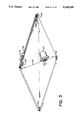
- FIG. 1 is a perspective view of the mechanism in a reader used to unlatch and remove the photosensitive element from the cassette and for transporting of the photosensitive material within a reader for obtaining of the latent image storage thereon, and insertion of the photosensitive element into the cassette and latching the cassette;
- FIG. 2 is a perspective view of the portion of the mechanism of FIG. 1 used to locate and unlatch and remove the photosensitive element from the cassette and later return the photosensitive element into the cassette;
- FIG. 3 is an exploded perspective view of the assembly of FIG. 2;
- FIG. 4 is a top plan view of the plate extraction mechanism of FIGS. 2 and 3 illustrating the extractor bar assembly in the neutral position;
- FIGS. 4A-4F illustrate the progressive movement of the extractor bar mechanism used in unlatching and removing the photosensitive element from the cassette
- FIG. 5 is a bottom perspective view of the mechanism of FIG. 3 illustrating the means used to move the extractor bar assembly toward and away from the cassette;
- FIG. 6 is a perspective view of a cassette designed for use with mechanism of FIGS. 1-5;
- FIG. 7 is an enlarged partial view of the cassette of FIG. 6 with removeable end cap removed.
- FIG. 8 is an enlarged cross-sectional view of the cassette of FIG. 6 as taken along line 8--8 with the end cap unlatched from the cassette.
- FIG. 9 is a perspective view of a cassette useful in the present invention.
- FIG. 10 is a cross-sectional view of the stage assembly shown in FIG. 1 taken along line 10--10.
- FIGS. 1-3 there is illustrated a mechanism 10 designed to be placed in a reader for scanning a photosensitive material.
- the mechanism 10 is designed to receive a cassette 12 having a photosensitive element disposed therein.
- the mechanism is designed to receive a cassette 12 having a stimulable phosphorus plate/sheet 14 (see FIG. 4F) capable of retaining a latent image thereon which upon photoradiation stimulation.
- a digital image can be extracted for later viewing or development of a x-ray film.
- photostimulable phosphorus plates are well known and described in the prior art.
- the reader is of the raster scanner-type as discussed in U.S. application Ser. No. 07/981,716 filed Nov.
- the stimulating of the stimulable plate by a laser beam is typically done using a raster scanning technique.
- the mechanism 10 includes a movable stage 16 which includes a drive screw 18 which is mounted to base 20 of the reader.
- the drive screw 18 is in threaded engagement with a drive nut 19 which engages the movable stage 16 by element 21 so as to move the stage 16 from the receiving position illustrated in FIG. 1 to the scanned position 22 illustrated by dash lines also in FIG. 1.
- An appropriate stepper motor 23 and corresponding transmission 25 is provided for rotating the drive screw 18 such that the stage 16 can move in the X direction.
- the stage 16 is supported by a pair of guide rails 24,26 which are axially spaced apart and secured to the base 20.
- the reader includes a clamping mechanism 24 which includes an upper clamp jaw 27 and lower clamp jaw 28 which are used to clamp the cassette in a predetermined fixed position.
- the details of this clamping mechanism may take a variety of constructions.
- a detailed description of a suitable clamping mechanism may be found in copending application entitled “Cassette Clamping Mechanism” of Michael Flynn, Wayne Arseneault, John Boutet, Jeffrey Yaskow, Thomas D. Baker, filed concurrently with this application, and which is also incorporate herein by reference.
- the mechanism 10 includes an extractor bar assembly 30 which is mounted to stage 16 for movement in the Y direction.
- the X and Y directions as set forth in this application have been provided merely for the sake of clarity in describing the direction of movement of various parts, it beingunderstood that any coordinate system may be substituted as desired.
- the extractor bar assembly 30 is designed for movement to and away from the cassette 12, while the stage 16 moves in a direction substantially transverse to the end/side of the cassette facing the extractor bar assembly 30.
- the cassette 12 is of the type designed forremoving the stimulable phosphorus element from the end/side of the cassette. Briefly, as shown in detail in FIGS.
- the cassette 12 comprises a shell having upper and lower panels 32,34, respectively, and three side caps 36,38,40.
- a photographic plate 14 of the photostimulable phosphorous type is disposed therein and is secured to a removable end cap42.
- the end cap 42 includes a latching mechanism for releasing the end cap 42 from the cassette 12. Additionally, the end cap 42 includes an alignment opening 44 disposed preferably along one side of the cassette 12.
- the end cap 42 further includes a plurality of access openings 46 designed to receive hook members designed to engage the latching mechanismdisposed within the cassette (not shown).
- the extractor bar assembly 30 includes a locator slide plate 48, and a extractor bar 50 which are secured to each other such that the extractor bar 50 can slide relative to the slide plate 48.
- the extractor bar 50 is designed to slide in the Ydirection with respect to the slide plate 48.
- a guide block 53 is provided and is secured to slide plate 48 by a screw 59 which extends through an opening in slide plate 48.
- the guide block slides within a mating slot 69 in extractor bar 50.
- a spring biases block 53 within slot 69.
- the extractor bar 50 includes a pair of guide supports 52, one secured at each lateral end 51.
- the guide-supports 52 are secured to extractor bar50 by a pair of screws 54 which extend through openings 56 in guide supports 52 which engage a pair of corresponding threaded openings 61 in extractor bar 50.
- the guide supports 52 have a projection 57 which extend into a mating recess 58 provided in the edge of the stage 16 which allows the extractor bar to move in the Y direction.
- a pair of TeflonTM guide-bearing plates 60 are secured to the lateral ends 51 of the extractor bar 50 and provide a bearing surface on which the extractor bar 50 slides along the top of stage 16.
- the bearing plates 60 are secured to the extractor bar 50 by a pair of screws 62 which extend through openings 66 in bearing plates 60 and engage threaded openings (not shown) in the extractor bar 50.
- a closure hook bar 68 Secured to the bottom of extractor bar 50 is a closure hook bar 68 having a plurality of hook members 70 designed to enter openings 46 provided in cassette 12 and for unlatching the latching mechanism disposed within the cassette 12.
- Thehook bar 68 may be secured to extractor bar 50 in any desired manner and, in the particular embodiment illustrated, is secured by a pair of shoulderscrews 72 which engage a pair of threaded openings (not shown) provided in the extractor bar 50.
- a pair of washers disposed on the sides of the hook bar 68.
- a spring washer 33 is disposed between the shoulder of the shoulder screw 72 and the adjacent washer 73.
- the spring washers 33 are bow washers. Mounting of the hook bar in this manner allows the hook bar 62 to move so that it can align vertically with the mating openings in the cassette.
- the extractor bar 50 is provided with a recess 74 at one end for enclosing slide pin assembly 76 which is secured to slide plate 48.
- the slide pin assembly 76 includes a locator pin 78 having an engagement end 80 which comprises an inner locating portion 82 and an annular registration surface 84.
- the locating portion 82 is designed to engage the alignment opening 44 in cassette 12 while the registration surface 84 is designed to engage the area of the cassette surrounding the opening 44.
- the slide pin assembly 76 includes a magnet collar 83 which is secured to the rear end 85 of pin 78.
- a spring 86 is provided for normally biasing the pin 78 outward toward the cassette12.
- An opening 88 is provided in the forward surface 90 of the extractor bar 50 which faces cassette 12 for allowing pin 78 to pass therethrough.
- the opening 88 is designed such that the pin 78 can move in a X direction with respect to the extractor bar 50 as will be discussed later herein.
- the slide plate 48 includes a top section 91 and a forward section 93 which is placed adjacent the forward surface 90 of extractor bar 50.
- the forward section 93 is provided with a plurality of openings 95,97,99 whichallow hook members 70 to extend therethrough. Opening 95 also permits pin 78 to also extend therethrough.
- Means are provided for biasing the slide plate 48 with respect to the extractor bar 50. In the particular embodiment illustrated, this is provided by a spring 96 which has one end secured to the slide plate 48 and the other end secured to the extractor bar 50. In the particular embodiment illustrated, the spring 96 is a extension spring.
- a second recess 92 is provided in extractor bar 50 for receiving a magnetichousing 94 which is secured to slide plate 48.
- magnetic housing 94 is secured by a screw 96 which engages a threaded opening 98 provided in magnetic housing and which passes through opening 100 in slide plate 48.
- the recess 92 is such that the magnetic housing 94 can move a predetermined distance in theX direction.
- the stage 16 is provided with a number of switches and sensors which are used to determine the location of the slide bar assembly 30 and provide information with regard to the status of the mechanism. These switches andsensors will be described in further detail in the description of the operation of the mechanism.
- a microprocessor (not shown) is provided in the reader as is typically done in the prior art. The microprocessor controls the operation of the various components provided and also monitors the various sensors provided in the device used to control and verify the operation of the reader.
- FIG. 5 there is illustrated the mechanism used to move the extractor bar assembly 30 in the Y direction on stage 16.
- a motor 122 is provided having a shaft to which is secured a drive pulley 124.
- the pulley 124 has a groove about its periphery designed to receive a cable 130.
- the cable is wrapped about the pulleys 120,124 in a closed loop.
- the cables are attached to the side projections such that when the motor is turned in a first direction, it will cause the extractor bar assembly 30 to move in a first Y direction and when rotated in the opposite direction, will cause the extractor bar assembly to move in the opposite Y direction. It is, of course, understoodthat any means may be employed for moving extractor bar assembly 30 in the Y direction.
- FIG. 4 there is illustrated a cassette 12 properly positionedwithin the clamp jaws 26,28 and the extractor bar assembly 30 is in the neutral position.
- the apparatus is first put into a seek position as illustrated in FIG. 4A.
- the extractor bar assembly 30 is positioned so that the pin 78 will be placed in a position downward of alignment opening 44 in cassette 12 such that the extractor bar assembly 30 must be moved in a positive X direction before the pin 78 will engage opening 44.
- the neutral position by definition, is a position which is downward of opening 44.
- the extractor bar assembly 30 is driven from the neutral position toward the cassette 12.
- the extractor bar assembly 30 is driven until sensor S1 senses magnetic housing 94 and will thus provide a signal to the microprocessor that the cassette is in the seek position.
- the distance D between the front of the cassette 12 and the front of the locator slide plate 48 is a predetermined distance.
- the distance D is such that the pin 78 is deflected slightly such that when the pin 78 engages the opening 44 in cassette 12, it will be able to pop into opening 44. In the particular embodiment illustrated the distance D is about 0.230 inches (0.5842 cms). From the seek position the stage 16 is driven in the positive X direction until the pin 78 engages opening 44, as shown in FIG.
- the stage 16 continues to be driven in the positive X direction until housing has moved a predetermined distance. Since a stepper motor 23 is used to move the stage 16, the stage can be moved a precise distance from the home position. However, since pin 78 hasengaged the opening 44 in cassette 12, the locator slide plate 48 will remain behind while the extractor bar 50 will continue with the stage 16 in the positive X direction. The stage 16 is driven until the hook members70 align with the access opening 46 in the cassette latching mechanism as illustrated in FIG. 4C. This position is verified by sensor S3 which senses magnetic housing 94.
- the stage 16 is then driven in the negative X direction until back at the home position where the locator pin 78 initially engaged the cassette as illustrated by FIG. 4E. This is easily accomplished as the stepper motor allows the stage to be driven back the exact distance it was moved initially therefrom. At this point, the cassette 12 has been unlatched. Verification of the position of the extractor bar 50 is made by reactivation of sensor S2.
- the extractor bar assembly 30 is then driven in the positive Y direction, removing the end cap 42 and stimulable phosphorus plate 14 from cassette 12.
- the extractor bar assembly 30 continues to be driven in the positive Ydirection until the plate has been fully extracted. This position is determined by actuation of switch SW2.
- the phosphorus plate 14 is now in position on the stage 16 for reading by the reader.
- the stage 16 is drivenin a negative X direction through the scan position 22 after which it is driven in the positive X direction to the erase position (not shown) for erasure. After erasure, the stage 16 with extractor bar assembly 30 is driven in the positive X direction until the extractor bar assembly 30 is in the home position for that cassette.
- the exact location for the home position can be recorded by the microprocessor. This home position can vary from cassette to cassette. As previously discussed, the home position is determined whenpin 78 engages opening 44. Therefore, the plate 14 can be easily realigned for placement back into cassette 12. Once in the home position, the extractor bar assembly 30 is driven in the negative Y direction until the cassette closure position switch SW1 is activated at which time the phosphorus plate 14 is then located back within the cassette 12.
- the stage 16 and hooks are driven in the positive X direction relatching the cassette 12. Verification of this relatching takes place when the embedded latch sensor S4 is actuated.
- the extractor bar assembly is then driven in the positive Y direction to the original entry position. This motion trips a hook position sensor S3 verifying the movement.
- the hook members 70 are now driven in the negative X direction to the original locator pin drop point (home position) and this position is verified by the actuation by locator pin sensor S2.
- the extraction bar assembly then moves in the positive Y direction. This position may be sensed by the plate side switch SW2, or may be a variable position obtained by driving assembly motor for a pre-set amount of time.
- the complete stage 16 moves in the negative X direction to the neutral position (as shown in FIG. 4) to complete the extraction cycle. At this time, the clamping mechanism is released for returning of the cassette 12 back to the autoloader or the operator as appropriate.
- the stage 16 may be provided with means for supporting the plate 14 when the extractor bar assembly 30 is in the fully retracted position as shown in FIG. 4F.
- a pair of retractable supports 132 are provided.
- the retractable supports 132 provide a sufficient upward support for supporting the bottom of plate, but are also of a design such that they can extend down into the stage 16 as the extractor bar assembly 30 passes thereover. It is, of course, understood that any desired number of supports may be provided so long as they do not interfere with the operation of the mechanism.
- means are provided for determining the size of the photostimulable plate 14.
- a plurality of sensor switches 134 FIG. 3 which are located such that, depending on which particular switches 134, FIG. 3 are being activated, the particular size of the plate can be readily determined.
- three switches 134 are used, however, any desired number may be provided and located as appropriate.
- the present invention provides a relatively simple mechanism for unlatchingand latching of a cassette, that is able to accurately locate the cassette even if the cassette is not presented exactly in the same position each time a cassette is fed to the mechanism and can also take into consideration normal manufacturing tolerances of the cassette.
Landscapes
- Physics & Mathematics (AREA)
- General Physics & Mathematics (AREA)
- Radiography Using Non-Light Waves (AREA)
- Photographic Developing Apparatuses (AREA)
- Sheets, Magazines, And Separation Thereof (AREA)
Priority Applications (4)
| Application Number | Priority Date | Filing Date | Title |
|---|---|---|---|
| US07/982,175 US5330309A (en) | 1992-11-25 | 1992-11-25 | Reader having cassette locating and unlatching mechanism |
| EP93118452A EP0601355B1 (de) | 1992-11-25 | 1993-11-16 | Lesegerät mit einem Kassettenauffinde- und Entriegelungsmechanismus |
| DE69313793T DE69313793T2 (de) | 1992-11-25 | 1993-11-16 | Lesegerät mit einem Kassettenauffinde- und Entriegelungsmechanismus |
| JP5293179A JPH07134347A (ja) | 1992-11-25 | 1993-11-24 | カセット位置決め及び係止解除機構を有する読取り器 |
Applications Claiming Priority (1)
| Application Number | Priority Date | Filing Date | Title |
|---|---|---|---|
| US07/982,175 US5330309A (en) | 1992-11-25 | 1992-11-25 | Reader having cassette locating and unlatching mechanism |
Publications (1)
| Publication Number | Publication Date |
|---|---|
| US5330309A true US5330309A (en) | 1994-07-19 |
Family
ID=25528903
Family Applications (1)
| Application Number | Title | Priority Date | Filing Date |
|---|---|---|---|
| US07/982,175 Expired - Fee Related US5330309A (en) | 1992-11-25 | 1992-11-25 | Reader having cassette locating and unlatching mechanism |
Country Status (4)
| Country | Link |
|---|---|
| US (1) | US5330309A (de) |
| EP (1) | EP0601355B1 (de) |
| JP (1) | JPH07134347A (de) |
| DE (1) | DE69313793T2 (de) |
Cited By (11)
| Publication number | Priority date | Publication date | Assignee | Title |
|---|---|---|---|---|
| US5493128A (en) * | 1994-08-25 | 1996-02-20 | Eastman Kodak Company | Method and apparatus for indexing cassettes |
| EP0600244B1 (de) * | 1992-11-25 | 1998-08-26 | Eastman Kodak Company | Kassettenklemmvorrichtung |
| US5954469A (en) * | 1997-09-23 | 1999-09-21 | Eastman Kodak Company | Extraction bar mechanism for storage phosphor reader |
| US5990487A (en) * | 1997-09-23 | 1999-11-23 | Eastman Kodak Company | Stage plunger mechanism for storage phosphor reader |
| US6032856A (en) * | 1997-09-23 | 2000-03-07 | Eastman Kodak Company | Storage phosphor reader using bar code for cassette extraction and alignment |
| US6176364B1 (en) | 1997-10-11 | 2001-01-23 | Eastman Kodak Company | Device for simplified vertical loading of an X-ray cassette into a transport receptacle of a processing apparatus for X-ray cassettes |
| US6278126B2 (en) | 1997-10-11 | 2001-08-21 | Eastman Kodak Company | Transport device for X-ray cassettes, each having a phosphor sheet stimulable by X-rays, in a cassette processing apparatus |
| US6696691B2 (en) | 2000-12-21 | 2004-02-24 | Eastman Kodak Company | Elongated computed radiography cassette having image alignment aid |
| US6852987B2 (en) | 2000-12-08 | 2005-02-08 | Eastman Kodak Company | Elongated computed radiography cassette |
| US20080245973A1 (en) * | 1999-11-24 | 2008-10-09 | Stephen Neushul | Computed radiography x-ray cassette with rigid embedded cr plate |
| US20090168970A1 (en) * | 2007-12-28 | 2009-07-02 | Jiake Xu | Casette tray and x-ray imaging apparatus |
Families Citing this family (1)
| Publication number | Priority date | Publication date | Assignee | Title |
|---|---|---|---|---|
| US7375350B2 (en) * | 1999-11-24 | 2008-05-20 | Neushul Stephen | Computed radiography x-ray cassette with rigid embedded CR plate |
Citations (31)
| Publication number | Priority date | Publication date | Assignee | Title |
|---|---|---|---|---|
| US3111585A (en) * | 1960-01-12 | 1963-11-19 | Gevaert Photo Prod Nv | Apparatus for unloading film sheet cassettes |
| US3881605A (en) * | 1973-06-29 | 1975-05-06 | Ibm | Object orienting device to assist robot manipulator |
| US3906325A (en) * | 1973-12-20 | 1975-09-16 | Olivetti & Co Spa | Adaptive feeling apparatus for determining a prearranged position in which a part is to be fitted |
| JPS5764928A (en) * | 1980-10-07 | 1982-04-20 | Nippon Kogaku Kk <Nikon> | Carrying apparatus for photo mask or reticle |
| US4354336A (en) * | 1980-01-15 | 1982-10-19 | Azzaroni Cesaro | Automatic machine for loading and unloading films in radiography cassettes |
| US4543480A (en) * | 1981-10-16 | 1985-09-24 | Fuji Photo Film Co. Ltd. | Radiation image recording system |
| US4611967A (en) * | 1984-07-06 | 1986-09-16 | Canon Kabushiki Kaisha | Cassette-type container for a sheet-like member |
| US4681227A (en) * | 1984-04-04 | 1987-07-21 | Fuji Photo Film Co., Ltd. | Cassette for stimulable phosphor sheet |
| US4682805A (en) * | 1986-02-18 | 1987-07-28 | The Perkin-Elmer Corporation | Grasping finger position sensor for a robot system |
| US4705953A (en) * | 1984-10-16 | 1987-11-10 | Fuji Photo Film Co., Ltd. | Radiation image recording and read-out apparatus with object data output capability |
| US4754144A (en) * | 1985-11-25 | 1988-06-28 | Fuji Photo Film Co., Ltd. | Radiation image read-out apparatus |
| US4758127A (en) * | 1983-06-24 | 1988-07-19 | Canon Kabushiki Kaisha | Original feeding apparatus and a cassette for containing the original |
| US4761554A (en) * | 1986-02-03 | 1988-08-02 | Fuji Photo Film Co., Ltd. | Radiation image read-out apparatus |
| US4771174A (en) * | 1986-07-11 | 1988-09-13 | Fuji Photo Film Co., Ltd. | Radiation image recording and read-out apparatus |
| US4775138A (en) * | 1986-03-29 | 1988-10-04 | Agfa Gevaert Aktiengesellschaft | Device for loading and unloading x-ray film cassettes |
| JPS63265445A (ja) * | 1988-03-11 | 1988-11-01 | Nikon Corp | 基板の保管、搬送装置 |
| US4789782A (en) * | 1986-08-15 | 1988-12-06 | Fuji Photo Film Co., Ltd. | Radiation image recording and reproducing system |
| US4820930A (en) * | 1984-06-20 | 1989-04-11 | Canon Kabushiki Kaisha | Photomask positioning device |
| US4827136A (en) * | 1987-11-27 | 1989-05-02 | Bishop Jr Gerald L | Cassette having photostimulable luminescent substrate |
| US4870285A (en) * | 1987-04-16 | 1989-09-26 | Fuji Photo Film Co., Ltd. | Cassette for information recording mediums |
| US4889989A (en) * | 1985-10-17 | 1989-12-26 | Fuji Photo Film Co., Ltd. | Cassette for image information recording carrier, mechanism for removing image information recording carrier from the cassette, and apparatus for reading image information |
| US4904868A (en) * | 1987-08-19 | 1990-02-27 | Fuji Photo Film Co., Ltd. | Radiation image read-out apparatus and stimulable phosphor sheet composite member for the same |
| US4908520A (en) * | 1987-04-17 | 1990-03-13 | Fuji Photo Film Co., Ltd. | Radiation image recording, read-out and reproducing apparatus |
| US4931641A (en) * | 1987-09-18 | 1990-06-05 | Fuji Photo Film Co., Ltd. | Radiation image read-out apparatus |
| US4950987A (en) * | 1989-03-03 | 1990-08-21 | University Of North Carolina At Charlotte | Magneto-inductive sensor for performing tactile and proximity sensing |
| US4987308A (en) * | 1983-01-21 | 1991-01-22 | Fuji Photo Film Co., Ltd. | Cassette for stimulable phosphor sheet |
| US5004393A (en) * | 1989-09-29 | 1991-04-02 | Storage Technology Corporation | Autoloader magazine for tape cartridges and method therefor |
| US5042223A (en) * | 1989-05-22 | 1991-08-27 | Alcatel Satmam | Article positioning control apparatus |
| US5081357A (en) * | 1989-10-18 | 1992-01-14 | Fuji Photo Film Co., Ltd. | Radiation image recording and read-out apparatus |
| US5107115A (en) * | 1990-08-23 | 1992-04-21 | Fuji Photo Film Co., Ltd. | Radiation image information reading apparatus |
| US5138160A (en) * | 1990-04-03 | 1992-08-11 | Fuji Photo Film Co., Ltd. | Storage type phosphor sheet holding device |
Family Cites Families (5)
| Publication number | Priority date | Publication date | Assignee | Title |
|---|---|---|---|---|
| US5124550A (en) * | 1990-11-30 | 1992-06-23 | Eastman Kodak Company | Apparatus for orienting storage phosphor cassette |
| EP0522317A1 (de) * | 1991-07-11 | 1993-01-13 | Eastman Kodak Company | Kassette für eine Röntgen-Phosphorspeicherplatte |
| US5328019A (en) * | 1992-11-25 | 1994-07-12 | Eastman Kodak Company | Autoloader for cassettes and/or pallet |
| US5329825A (en) * | 1992-11-25 | 1994-07-19 | Eastman Kodak Company | Precision moving stage |
| US5315632A (en) * | 1992-11-25 | 1994-05-24 | Eastman Kodak Company | Cassette clamping mechanism |
-
1992
- 1992-11-25 US US07/982,175 patent/US5330309A/en not_active Expired - Fee Related
-
1993
- 1993-11-16 DE DE69313793T patent/DE69313793T2/de not_active Expired - Fee Related
- 1993-11-16 EP EP93118452A patent/EP0601355B1/de not_active Expired - Lifetime
- 1993-11-24 JP JP5293179A patent/JPH07134347A/ja active Pending
Patent Citations (31)
| Publication number | Priority date | Publication date | Assignee | Title |
|---|---|---|---|---|
| US3111585A (en) * | 1960-01-12 | 1963-11-19 | Gevaert Photo Prod Nv | Apparatus for unloading film sheet cassettes |
| US3881605A (en) * | 1973-06-29 | 1975-05-06 | Ibm | Object orienting device to assist robot manipulator |
| US3906325A (en) * | 1973-12-20 | 1975-09-16 | Olivetti & Co Spa | Adaptive feeling apparatus for determining a prearranged position in which a part is to be fitted |
| US4354336A (en) * | 1980-01-15 | 1982-10-19 | Azzaroni Cesaro | Automatic machine for loading and unloading films in radiography cassettes |
| JPS5764928A (en) * | 1980-10-07 | 1982-04-20 | Nippon Kogaku Kk <Nikon> | Carrying apparatus for photo mask or reticle |
| US4543480A (en) * | 1981-10-16 | 1985-09-24 | Fuji Photo Film Co. Ltd. | Radiation image recording system |
| US4987308A (en) * | 1983-01-21 | 1991-01-22 | Fuji Photo Film Co., Ltd. | Cassette for stimulable phosphor sheet |
| US4758127A (en) * | 1983-06-24 | 1988-07-19 | Canon Kabushiki Kaisha | Original feeding apparatus and a cassette for containing the original |
| US4681227A (en) * | 1984-04-04 | 1987-07-21 | Fuji Photo Film Co., Ltd. | Cassette for stimulable phosphor sheet |
| US4820930A (en) * | 1984-06-20 | 1989-04-11 | Canon Kabushiki Kaisha | Photomask positioning device |
| US4611967A (en) * | 1984-07-06 | 1986-09-16 | Canon Kabushiki Kaisha | Cassette-type container for a sheet-like member |
| US4705953A (en) * | 1984-10-16 | 1987-11-10 | Fuji Photo Film Co., Ltd. | Radiation image recording and read-out apparatus with object data output capability |
| US4889989A (en) * | 1985-10-17 | 1989-12-26 | Fuji Photo Film Co., Ltd. | Cassette for image information recording carrier, mechanism for removing image information recording carrier from the cassette, and apparatus for reading image information |
| US4754144A (en) * | 1985-11-25 | 1988-06-28 | Fuji Photo Film Co., Ltd. | Radiation image read-out apparatus |
| US4761554A (en) * | 1986-02-03 | 1988-08-02 | Fuji Photo Film Co., Ltd. | Radiation image read-out apparatus |
| US4682805A (en) * | 1986-02-18 | 1987-07-28 | The Perkin-Elmer Corporation | Grasping finger position sensor for a robot system |
| US4775138A (en) * | 1986-03-29 | 1988-10-04 | Agfa Gevaert Aktiengesellschaft | Device for loading and unloading x-ray film cassettes |
| US4771174A (en) * | 1986-07-11 | 1988-09-13 | Fuji Photo Film Co., Ltd. | Radiation image recording and read-out apparatus |
| US4789782A (en) * | 1986-08-15 | 1988-12-06 | Fuji Photo Film Co., Ltd. | Radiation image recording and reproducing system |
| US4870285A (en) * | 1987-04-16 | 1989-09-26 | Fuji Photo Film Co., Ltd. | Cassette for information recording mediums |
| US4908520A (en) * | 1987-04-17 | 1990-03-13 | Fuji Photo Film Co., Ltd. | Radiation image recording, read-out and reproducing apparatus |
| US4904868A (en) * | 1987-08-19 | 1990-02-27 | Fuji Photo Film Co., Ltd. | Radiation image read-out apparatus and stimulable phosphor sheet composite member for the same |
| US4931641A (en) * | 1987-09-18 | 1990-06-05 | Fuji Photo Film Co., Ltd. | Radiation image read-out apparatus |
| US4827136A (en) * | 1987-11-27 | 1989-05-02 | Bishop Jr Gerald L | Cassette having photostimulable luminescent substrate |
| JPS63265445A (ja) * | 1988-03-11 | 1988-11-01 | Nikon Corp | 基板の保管、搬送装置 |
| US4950987A (en) * | 1989-03-03 | 1990-08-21 | University Of North Carolina At Charlotte | Magneto-inductive sensor for performing tactile and proximity sensing |
| US5042223A (en) * | 1989-05-22 | 1991-08-27 | Alcatel Satmam | Article positioning control apparatus |
| US5004393A (en) * | 1989-09-29 | 1991-04-02 | Storage Technology Corporation | Autoloader magazine for tape cartridges and method therefor |
| US5081357A (en) * | 1989-10-18 | 1992-01-14 | Fuji Photo Film Co., Ltd. | Radiation image recording and read-out apparatus |
| US5138160A (en) * | 1990-04-03 | 1992-08-11 | Fuji Photo Film Co., Ltd. | Storage type phosphor sheet holding device |
| US5107115A (en) * | 1990-08-23 | 1992-04-21 | Fuji Photo Film Co., Ltd. | Radiation image information reading apparatus |
Cited By (13)
| Publication number | Priority date | Publication date | Assignee | Title |
|---|---|---|---|---|
| EP0600244B1 (de) * | 1992-11-25 | 1998-08-26 | Eastman Kodak Company | Kassettenklemmvorrichtung |
| US5493128A (en) * | 1994-08-25 | 1996-02-20 | Eastman Kodak Company | Method and apparatus for indexing cassettes |
| EP0698813A1 (de) | 1994-08-25 | 1996-02-28 | Eastman Kodak Company | Verfahren und Vorrichtung zur Auswahl von Kassetten |
| US5954469A (en) * | 1997-09-23 | 1999-09-21 | Eastman Kodak Company | Extraction bar mechanism for storage phosphor reader |
| US5990487A (en) * | 1997-09-23 | 1999-11-23 | Eastman Kodak Company | Stage plunger mechanism for storage phosphor reader |
| US6032856A (en) * | 1997-09-23 | 2000-03-07 | Eastman Kodak Company | Storage phosphor reader using bar code for cassette extraction and alignment |
| US6176364B1 (en) | 1997-10-11 | 2001-01-23 | Eastman Kodak Company | Device for simplified vertical loading of an X-ray cassette into a transport receptacle of a processing apparatus for X-ray cassettes |
| US6278126B2 (en) | 1997-10-11 | 2001-08-21 | Eastman Kodak Company | Transport device for X-ray cassettes, each having a phosphor sheet stimulable by X-rays, in a cassette processing apparatus |
| US20080245973A1 (en) * | 1999-11-24 | 2008-10-09 | Stephen Neushul | Computed radiography x-ray cassette with rigid embedded cr plate |
| US6852987B2 (en) | 2000-12-08 | 2005-02-08 | Eastman Kodak Company | Elongated computed radiography cassette |
| US6696691B2 (en) | 2000-12-21 | 2004-02-24 | Eastman Kodak Company | Elongated computed radiography cassette having image alignment aid |
| US20090168970A1 (en) * | 2007-12-28 | 2009-07-02 | Jiake Xu | Casette tray and x-ray imaging apparatus |
| US7575373B2 (en) * | 2007-12-28 | 2009-08-18 | Ge Medical Systems Global Technology Company, Llc | Cassette tray and X-ray imaging apparatus |
Also Published As
| Publication number | Publication date |
|---|---|
| DE69313793D1 (de) | 1997-10-16 |
| EP0601355B1 (de) | 1997-09-10 |
| JPH07134347A (ja) | 1995-05-23 |
| DE69313793T2 (de) | 1998-04-02 |
| EP0601355A1 (de) | 1994-06-15 |
Similar Documents
| Publication | Publication Date | Title |
|---|---|---|
| US5330309A (en) | Reader having cassette locating and unlatching mechanism | |
| US4858003A (en) | Mechanism for handling slides and film strips | |
| US5461492A (en) | Film scanner with in-line dual scanning gates | |
| US5663806A (en) | Non-destructive target marking for image stitching | |
| US3973344A (en) | Multi-image slide mount | |
| JPH0448381B2 (de) | ||
| US6643565B2 (en) | Self aligning robotic arm calibration apparatus | |
| GB1584000A (en) | Two directional transport arrangement | |
| EP0135723B1 (de) | Strahlungsbild-Photographiergerät | |
| US5889547A (en) | Registration detection apparatus for imaging systems | |
| US4799072A (en) | Separate-exposure photographing apparatus | |
| US5555042A (en) | Apparatus for automatically feeding slides into a film scanner | |
| US5067702A (en) | Dispenser for dispensing sheets of an alternating first and second kind from a stack | |
| US3704945A (en) | Photoplotter accurate film locating mechanism | |
| US5990487A (en) | Stage plunger mechanism for storage phosphor reader | |
| EP0690608A2 (de) | Filmabtastsystem und -verfahren | |
| US5954469A (en) | Extraction bar mechanism for storage phosphor reader | |
| US4965631A (en) | Device for mounting photographic negative carrier | |
| US6002495A (en) | Imaging system with moveable registration pins | |
| US4493540A (en) | Transport apparatus for microfiche cards | |
| GB2169166A (en) | Roll film document image storage & retrieval apparatus | |
| US4483600A (en) | Microfiche card transport apparatus | |
| US6505413B2 (en) | Position adjusting mechanism and image scanning apparatus with such position adjusting mechanism | |
| US4531829A (en) | Multi-form slide selection apparatus | |
| US20060131525A1 (en) | Short U-flow multicassette autoloader for a storage phosphor reader |
Legal Events
| Date | Code | Title | Description |
|---|---|---|---|
| AS | Assignment |
Owner name: EASTMAN KODAK COMPANY, NEW YORK Free format text: ASSIGNMENT OF ASSIGNORS INTEREST.;ASSIGNORS:BRAHM, ROGER S.;LATTIMORE, JAMES D.;REEL/FRAME:006418/0479;SIGNING DATES FROM 19921124 TO 19921206 |
|
| FEPP | Fee payment procedure |
Free format text: PAYOR NUMBER ASSIGNED (ORIGINAL EVENT CODE: ASPN); ENTITY STATUS OF PATENT OWNER: LARGE ENTITY |
|
| FEPP | Fee payment procedure |
Free format text: PAYER NUMBER DE-ASSIGNED (ORIGINAL EVENT CODE: RMPN); ENTITY STATUS OF PATENT OWNER: LARGE ENTITY Free format text: PAYOR NUMBER ASSIGNED (ORIGINAL EVENT CODE: ASPN); ENTITY STATUS OF PATENT OWNER: LARGE ENTITY |
|
| FPAY | Fee payment |
Year of fee payment: 4 |
|
| FPAY | Fee payment |
Year of fee payment: 8 |
|
| REMI | Maintenance fee reminder mailed | ||
| LAPS | Lapse for failure to pay maintenance fees | ||
| STCH | Information on status: patent discontinuation |
Free format text: PATENT EXPIRED DUE TO NONPAYMENT OF MAINTENANCE FEES UNDER 37 CFR 1.362 |
|
| FP | Lapsed due to failure to pay maintenance fee |
Effective date: 20060719 |