US5452346A - Telephone apparatus with caller identification - Google Patents
Telephone apparatus with caller identification Download PDFInfo
- Publication number
- US5452346A US5452346A US08/233,452 US23345294A US5452346A US 5452346 A US5452346 A US 5452346A US 23345294 A US23345294 A US 23345294A US 5452346 A US5452346 A US 5452346A
- Authority
- US
- United States
- Prior art keywords
- telephone number
- number data
- telephone
- name
- memory
- Prior art date
- Legal status (The legal status is an assumption and is not a legal conclusion. Google has not performed a legal analysis and makes no representation as to the accuracy of the status listed.)
- Expired - Fee Related
Links
Images




Classifications
-
- H—ELECTRICITY
- H04—ELECTRIC COMMUNICATION TECHNIQUE
- H04M—TELEPHONIC COMMUNICATION
- H04M1/00—Substation equipment, e.g. for use by subscribers
- H04M1/57—Arrangements for indicating or recording the number of the calling subscriber at the called subscriber's set
- H04M1/575—Means for retrieving and displaying personal data about calling party
-
- H—ELECTRICITY
- H04—ELECTRIC COMMUNICATION TECHNIQUE
- H04M—TELEPHONIC COMMUNICATION
- H04M3/00—Automatic or semi-automatic exchanges
- H04M3/42—Systems providing special services or facilities to subscribers
- H04M3/42025—Calling or Called party identification service
- H04M3/42034—Calling party identification service
- H04M3/42042—Notifying the called party of information on the calling party
-
- H—ELECTRICITY
- H04—ELECTRIC COMMUNICATION TECHNIQUE
- H04M—TELEPHONIC COMMUNICATION
- H04M1/00—Substation equipment, e.g. for use by subscribers
- H04M1/57—Arrangements for indicating or recording the number of the calling subscriber at the called subscriber's set
- H04M1/573—Line monitoring circuits for detecting caller identification
-
- H—ELECTRICITY
- H04—ELECTRIC COMMUNICATION TECHNIQUE
- H04M—TELEPHONIC COMMUNICATION
- H04M1/00—Substation equipment, e.g. for use by subscribers
- H04M1/57—Arrangements for indicating or recording the number of the calling subscriber at the called subscriber's set
- H04M1/575—Means for retrieving and displaying personal data about calling party
- H04M1/578—Means for retrieving and displaying personal data about calling party associated with a synthesized vocal announcement
-
- H—ELECTRICITY
- H04—ELECTRIC COMMUNICATION TECHNIQUE
- H04W—WIRELESS COMMUNICATION NETWORKS
- H04W68/00—User notification, e.g. alerting and paging, for incoming communication, change of service or the like
Definitions
- the present invention relates to a telephone apparatus. More particularly the present invention relates to a telephone apparatus having a function of supplying a reception (called) side with information on a calling (transmitting) side such as telephone number information.
- FIGS. 1A and 1B are diagrams showing a time chart and a format of the reception bell signals transmitted to the reception side.
- modem data containing information on the telephone number of a calling side is inserted between first and second bell signals as shown in FIG. 1A.
- a bell signal is used to ring a bell of a telephone at the reception side, and it includes, for example, a 20 Hz signal which is continuous for two seconds (corresponding to one bell sound).
- the modem data having data length corresponding to four seconds is inserted after 0.5 second elapses subsequently to a first bell signal.
- a second bell signal is located so as to be continuous for two seconds after 0.5 second elapses subsequently to the modem data.
- the similar bell signals each of which is continuous for two seconds, are intermittently transmitted at a time interval of 5 seconds until an user at the reception side answers the call.
- the modem data is inserted only between the first and second bell signals.
- the modem data includes a synchronizing signal consisting of a repetition of "1", "0" which are alternately repeated over 240 bits at the head of the modem data, and subsequently a signal having a train of "1" (mark) each continuing for 25 msec over 150 msec. This signal is used to identify the head of the data.
- the modem data finally includes information on month, date, hour, minute and telephone number. This information on month, date, hour, minute and telephone number are respectively set with 144 bits in the U.S.A., and with about 250 bits in Canada.
- the telephone number of a calling side can be detected before a reception side receives and answers the phone from the calling side.
- the telephone number of the calling side which is obtained by decoding the modem data as described above is displayed on a display unit such as an LCD (Liquid Crystal Display).
- a display unit such as an LCD (Liquid Crystal Display).
- LCD Liquid Crystal Display
- the name of a telephone subscriber is transmitted together with information on the telephone number thereof between the reception bell signals.
- loads such as installation of a new switchboard, etc. must be imposed on a telephone office side, and thus this service has hardly propagated.
- a telephone apparatus is equipped with a dictionary memory in which the telephone numbers of calling sides and the corresponding names of the calling sides can be registered.
- transmitted information on a telephone number is decoded on the basis of the Call Display telephone service to compare the telephone number data with each of the registered telephone numbers read out from the dictionary memory, and if any telephone number is coincident with the transmitted telephone number data, the name data of the coincident telephone number is read out and displayed on a display unit such as an LCD.
- a telephone apparatus including a decoder, a memory, a comparison circuit and an output device.
- the decoder serves to detect information concerning the telephone number of a calling side which is transmitted together with bell signals through a telephone line to decode the information of the telephone number.
- the memory serves to store data relating to the telephone numbers of calling sides in correspondence with plural selection keys.
- the comparison circuit serves to compare the output data from the data from the decoder (i.e., the decoded information of the telephone number transmitted through the telephone line) with the telephone number data stored in the memory when a call is received through a telephone line (at a reception time).
- the output device serves to inform the reception side that the reception corresponds to the telephone number data which have been already stored in the memory when the comparison result of the comparison circuit represents coincidence between the data on the telephone numbers stored in the memory and the output data from the decoder.
- a telephone apparatus including a decoder, a memory, an name-writing area, a display device, a comparison circuit and a driving circuit.
- the decoder serves to detect information on the telephone number of a calling side which is transmitted through a telephone line to decode the information on the telephone number.
- the memory serves to store the telephone number data of calling sides in correspondence with plural selection keys.
- the name-writing area is an area in which the names of the calling sides corresponding to the telephone number data stored in the memory can be written in accordance with the keys.
- the display device serves to indicate the name portion of the calling sides which is written in the name-writing area.
- the comparison circuit serves to read out the telephone number data from the memory when a call is received through a telephone line and information on the telephone number of a calling side is detected, and compare the read-out telephone number data with the output data of the decoder.
- the driving circuit serves to drive the display device to indicate the name portion of the calling side in the name-writing area which corresponds to the detected telephone number data.
- a telephone apparatus including a decoder, a memory, a recording and reproducing unit, a speaker unit, a comparison circuit and a controller.
- the decoder serves to detect information on the telephone number of a calling side which is transmitted through a telephone line to decode the information on the telephone number.
- the memory serves to store the telephone number data of calling sides in correspondence with the key selection of plural keys.
- the recording and reproducing unit serves to record and reproduce as audio data the names of calling sides corresponding to telephone number data which are stored in the memory in correspondence with plural selection keys.
- the speaker unit is supplied with the audio data outputted from the recording and reproducing unit.
- the comparison circuit serves to read out the telephone number data from the memory when a call is received through a telephone line and information on the telephone number of a calling side is detected, and compare the read-out telephone number data with the output data of the decoder.
- the controller serves to drive the speaker unit to reproduce and output the audio data corresponding to the detected telephone number data from the recording and reproducing unit.
- a telephone apparatus including a decoder, first and second memories, a name-writing area, a display device, a comparison and coincidence circuit and a driving circuit.
- the decoder serves to detect information on the telephone number of a calling side which is transmitted together with a reception bell sound through a telephone line to decode the information on the telephone number.
- the first memory serves to store the telephone number data decoded by the decoder.
- the second memory serves to store the telephone numbers of calling sides in correspondence with plural manipulation keys.
- the name-writing area is an area in which the names of the calling sides corresponding to the telephone number data stored in the second memory can be written in accordance with the key manipulation.
- the display device serves to indicate the name portion of the calling sides written in the name-writing area.
- the comparison and coincidence circuit serves to reads out the telephone number data from the first memory and the telephone number from the second memory when receiving a search instruction, and compares these read-out telephone number data to detect whether any coincident telephone number data exists.
- the driving circuit drives the display device to indicate the name portion of the calling side in the name-writing area, which corresponds to the detected telephone number data.
- a telephone apparatus including a decoder, first and second memories, a recording and reproducing unit, a speaker unit, a comparison and coincidence circuit and a controller.
- the decoder serves to detect information on the telephone number of a calling side which is transmitted through a telephone line to decode the information on the telephone number.
- the first memory serves to store the telephone number data decoded by the decoder.
- the second memory serves to store the telephone numbers of calling sides in correspondence with plural manipulation keys.
- the recording and reproducing unit serves to record and reproduce as audio data the names of calling sides corresponding to telephone number data which are stored in the memory in correspondence with plural manipulation keys.
- the speaker unit is supplied with the audio data outputted from the recording and reproducing unit.
- the comparison circuit serves to read out the telephone number data from the memory when a call is received through a telephone line and information on the telephone number of a calling side is detected, and compare the read-out telephone number data with the output data of the decoder.
- the controller serves to drive the speaker unit to reproduce and output the audio data corresponding to the detected telephone number data from the recording and reproducing unit.
- a telephone number including a decoder, a memory, display units, a comparison circuit and a controller.
- the decoder serves to detect information on the telephone number of a calling side which is transmitted together with bell signals through a telephone line to decode the telephone number data.
- the memory serves to store data on the telephone numbers of calling sides in correspondence with plural selection keys.
- the display units are provided in correspondence with the respective selection keys.
- the comparison circuit serves to compare the output data of the decoder (the decoded data on the telephone number transmitted through the telephone line) with the information on the telephone numbers stored in the memory when a call is received. When the comparison result of the comparison circuit represents coincidence between one of the telephone number data stored in the memory and the output data of the decoder, the controller selectively drives the display unit of the selection key corresponding to the coincident telephone number data.
- a telephone apparatus including a decoder, a memory, first and second display units, a comparison circuit and a controller.
- the decoder serves to detect information on the telephone number of a calling side which is transmitted together with bell signals through a telephone line to decode the telephone number data.
- the memory serves to store data on the telephone numbers of calling sides in correspondence with plural selection keys.
- the first display units are provided in correspondence with the respective selection keys.
- the second display unit serves to display the data decoded by the decoder.
- the comparison circuit serves to compare the output data of the decoder (the decoded data on the telephone number transmitted through the telephone line) with the information on the telephone numbers stored in the memory when a call is received.
- the controller selectively drives the first display unit of the selection key corresponding to the coincident telephone number data.
- the controller drives the first and second display units so that the telephone number data of the calling side which is decoded by the decoder is not displayed on any first display unit.
- the telephone numbers which have been stored in the memory in correspondence with the selection keys are compared with the received telephone number, and if any coincident telephone number is detected, the display unit corresponding to the selection key for the coincident telephone number is turned on, whereby an user can easily identify the calling side. Further, the same effect can be obtained by reading out and outputting the name data which have been previously stored in the memory in correspondence with calling sides when any coincident telephone number is found.
- FIGS. 1A and 1B are diagrams showing a time chart and a format of the reception bell signals transmitted to the reception side;
- FIG. 2 shows an outline of an operation panel of a first embodiment of a telephone apparatus according to this invention
- FIG. 3 is a circuit diagram of the first embodiment of the telephone apparatus according to this invention.
- FIG. 4 is a block diagram showing the construction of a main part of the first embodiment of the telephone apparatus according to this invention.
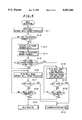
- FIG. 5 is a flowchart for the main part of the first embodiment of this invention.
- FIG. 6 is another flowchart for the main part of the first embodiment of this invention.
- FIG. 7 is a block diagram of a second embodiment of the telephone apparatus according to this invention.
- FIG. 8 is a flowchart for the operation of the embodiment of FIG. 7.
- FIG. 2 shows the outline of an embodiment of the telephone apparatus according to this invention.
- reference numeral 1 represents a main body of the telephone apparatus
- reference numeral 2 represents a hand set
- reference numeral 3 represents a numeric key for inputting a telephone number
- reference numeral 4 represents a display unit for displaying the input telephone number, a time, etc.
- the display unit 4 is composed of an LCD, for example.
- Reference numeral 10 represents a one-touch operation portion, and it is provided with a plurality one-touch keys 5 and a name plate 6 for indicating the names of call sides (those which will call or be called to the user through a telephone line).
- call side in this specification means a called side (a receiver) when the user of this apparatus is a calling side (transmitter), and it means a calling side (transmitter) when the user of this apparatus is a called side (receiver).
- the call sides are registered in correspondence with the respective one-touch keys 5.
- 16 one-touch keys are provided, and the names of the registered call sides are written on the name plate in correspondence with the respective one-touch keys 5 by user's hand-writing or other means.
- a one-touch dial registration is carried out by pushing a one-touch key, inputting the telephone number of a call side and then pushing a prescribed enter key. Through this operation, the telephone numbers of call sides are stored in a memory in correspondence with the respective one-touch keys 5.
- the telephone number of a call side which corresponds to the pushed one-touch key 5 is read out from the memory, and an automatic dialing is performed. That is, the dialing of the telephone number can be performed by merely pushing the one-touch key without full dialing. In this case, the telephone number of the call side is displayed on the display unit 4.
- the one-touch keys 5 and a name-writing area in-which the names are hand-written are provided. Therefore, in order to indicate (identify) a call side, LEDs (Light-Emitting Diodes) 7 are provided for the respective one-touch keys 5 in the vicinity of the name-writing area.
- the corresponding LED 7 is turned on, and the name of a call side can be confirmed by looking at the name plate 6.
- the telephone number of the call side is displayed on the display unit 4, and the call side can be further reconfirmed.
- the above operation is substantially identical to that of a general telephone apparatus except for the LEDs 7 serving as the display device.
- the telephone apparatus of this embodiment is different from the general telephone apparatus as follows. That is, when information on the telephone number of a calling side which is contained between first and second bell signals in transmitted modem data is detected at a call reception time, the information on the telephone number (telephone number data) is decoded. The decoded telephone number data is compared with the telephone number data which are stored in correspondence with the respective one-touch keys 5 in the memory. If there is any coincident telephone number data, the LED 7 located near to the one-touch key 5 for which the coincident telephone number is registered as a one-touch dial is turned on and off in accordance with the bell signals.
- the name-writing area on the name plate is indicated by the LED 7.
- the user or called side can easily identify the name of the calling side on the basis of the name-writing area.
- the user can directly write the name of the person on the name plate. For example, when the name of a father is register as a subscriber, but his daughter actually uses the telephone of the subscriber to call the user with the telephone, it would be often confusing to display the name of the subscriber on a display unit utilizing the Name Display telephone service.
- the user can freely write the name of any person on the name plate, and the names of persons other than subscribers whom the user knows well can be indicated. These are very convenient for the user.
- FIG. 3 is a circuit diagram showing the telephone apparatus, and this telephone apparatus is implemented by an IC technique.
- L1 and L2 represent a telephone line, and are connected to a modular jack 11 provided for the telephone apparatus.
- Each of reference numerals 12, 13 and 14 represents a bridge circuit.
- Reference numeral 15 represents a ringer circuit composed of an integrated circuit (IC);
- reference numeral 16 denotes a demodulator composed of an IC;
- reference numeral 18 denotes a speech circuit composed of an IC; and
- reference numeral 19 denotes a DC power source.
- Reference numeral 100 represents a microcomputer, and the microcomputer 100 is connected to the LCD display unit 4, a one-touch LED group 22 a plurality plural LEDs which are provided in correspondence with the respective one-touch keys 5 as shown in FIG. 2, and an operation key group 23 including the one-touch keys 5, the numeral key 3 and the other keys.
- the LED group 22 is designed in a matrix form.
- the microcomputer 100 is designed to be reset by a rest circuit 24 which is actuated in accordance with a hook switch HK.
- Reference numeral 25 represents a bell sound tone switching circuit for altering bell sound tone.
- the microcomputer 100 includes a one-touch memory for storing telephone numbers which are registered in correspondence with the respective a plurality one-touch keys 5, and a telephone number for storing the telephone number of a calling side which is transmitted through the telephone lines L1 and L2.
- a work area of a so-called work RAM is usable for these memories.
- Reference numeral 27 is a circuit for adjusting the sound volume of the bell, and in FIG. 3 the circuit 27 is switched to a state where no bell sound is produced.
- the data When modem data are transmitted between first and second reception bell signals, the data are detected and demodulated by the demodulator 16.
- the demodulated data containing the telephone number information of the calling side are input to the microcomputer 100.
- the demodulator 16 also detects the reception bell signals, and supplies ring signals as a reception detection signal to the microcomputer 100.
- the microcomputer 100 decodes the telephone number data, etc. from the demodulated output signal of the demodulator 16, and transmits the decoded output signal thereof to an LCD display circuit 21. Through this operation, the telephone number of the calling side, etc. are displayed on the display unit 4.
- the microcomputer 100 also serves to successively compare the telephone number data obtained by decoding the demodulated output signal of the demodulator 16 with the telephone number data stored in the one-touch memory. If any coincident telephone number data is detected on the basis of the comparison result, the microcomputer 100 controls the driving of the one-touch LED group 22 so that the LED for the coincident telephone number is turned on and off. At the same time, if any coincident telephone number data exists, for the purpose of making the user aware by with sound, that the received call is made by an acquaintance which is registered for a one-touch key, the microcomputer 100 drives the sound tone switching circuit 25 and controls the ringer circuit 15 to alter the sound tone of reproduced sound of the bell 26. If no coincident telephone number data is detected, the telephone number data obtained by decoding the demodulated signal from the demodulator 16 are supplied to the LCD display circuit 21 to display the received telephone number on the display unit 4.
- the hook switch HK When the user picks up the hand set 2 in response to the call reception, the hook switch HK is turned on, and the microcomputer 100 detects the turn-on of the hook switch HK. The microcomputer 100 transmits a control signal to the speech circuit 18 to enable a telephonic communication with the calling side.
- the microcomputer 100 When a transmission is made by operating a one-touch key 5 or performing a dialing with the numeral key 3, the microcomputer 100 transmits a dial signal for the telephone number of a calling side to the circuits L1 and L2 through a dial pulse circuit 17.
- the bell circuit 150 is actuated by the first bell signal, so that the bell 26 rings to produce normal bell sound.
- a reception and telephone number detecting circuit 160 containing the demodulator 16 and a part of the microcomputer 100 detects the call reception, and transmits a detection signal to the communication circuit 180.
- the detecting circuit 160 demodulates the modem data, and decodes the telephone number data and other information.
- the decoded telephone number data is written into a telephone number memory 101 provided to the microcomputer 100.
- a read-out/write-in control circuit 102 is actuated to write the decoded telephone number data into the memory 101. Further, the read-out/write-in control circuit 102 reads out written telephone number data and transmits it to the LCD display circuit 21. The decoded telephone number data are displayed together with time information on the display unit 4. At the same time, the telephone number data read out from the memory 101 are supplied to a coincidence and comparison circuit 103.
- the reception and telephone number detecting circuit 160 supplies the read-out/write-in control circuit 104 with a detection signal representing that the telephone number information is contained in the reception signal of the modem data.
- the read-out/write-in control circuit 104 successively reads out from the one-touch memory 105 the telephone number data representing a plurality telephone numbers which were previously stored in the one-touch memory 105 while registered in correspondence with the respective one-touch keys, and transmits these data to the coincidence and comparison circuit 103.
- a display control circuit 106 generates a driving signal for turning on and off the LEDs 7 which is located near to the one-touch key 5 registered for the coincidence telephone number.
- one of the LEDs 7 for the corresponding one-touch key of the one-touch key group 22 is turned on and off in accordance with (in synchronism with) the bell signals.
- the output signal of the coincidence and comparison circuit 103 is supplied to a sound tone switching circuit 250 including a part of the microcomputer 100 and the sound tone switching circuit 25.
- the sound tone switching circuit 250 receives the output signal of the circuit 103 to alter the sound tone of the second and subsequent bell signals toga sound tone which is different from that of the first bell signal, whereby an user or receiver is made aware that the call is made by a person who is registered for the one-touch key 5 next to the LED which is turned on and off.
- the one-touch memory 105 are successively stored telephone number data corresponding to the respective one-touch keys which have been registered by selection of the one-touch keys 5 and the numeral key 3 in the key group 23 containing the one-touch keys and the other keys by the one-touch registering circuit 107.
- the read-out/write-in control circuit 104 is controlled by the one-touch registering circuit 107 to perform the write-in operation of the telephone number data into the memory 105.
- the hand set 2 In response to the calling reception, the hand set 2 is lifted up and the hook switch HK is switched on in the communication circuit 180, so that a telephonic communication is allowed to be performed.
- the embodiment shown in FIG. 4 is designed so that several call events can be successively stored in the telephone number memory 101. That is, when a call has model data between bell signals, the read-out/write-in control circuit 102 receives the detection output signal of the detecting circuit 160, and successively writes telephone number data and time data of a permissible number of calls at serial addresses in the memory 101.
- the user can search a plurality of received calls later with the reception review circuit 108, and the telephone apparatus is equipped with a key switch to perform the searching operation.
- the reception review circuit 108 is actuated and the read-out/write-in control circuit 102 is driven to successively read out the stored telephone number data of calling sides.
- the telephone number data thus read out are successively transmitted to the LCD display circuit 21 to display the telephone numbers on the display unit 4.
- a re-call when a re-call is required to be made with looking at the display unit, the telephone number to be re-called can be automatically dialed by pushing a send key.
- the user can easily determine know the name of the calling side by seeing the name plate. For example, when a calling side is an user's acquaintance who is registered for a one-touch,key 5 and the user wants to re-call the acquaintance, the user can easily check the name of the acquaintance with the name-writing area of the name plate in the vicinity of the turned-on LED 7. In this case, the re-call can be made pushing not only the one-touch key 5, but also the send key.
- FIG. 5 is a flowchart showing the operation of the microcomputer 100 at the call reception time.
- step S1-1 When a call is received, a first bell sound is produced as a normal sound by ringing the bell 26 (step S1-1). Subsequently, the program goes to a step S1-2 to judge on the basis of demodulated data from the demodulator 16 whether telephone number data are transmitted between first and second bell signals. If the telephone number data are judged to be transmitted, the program goes from the step S1-2 to a step S1-3, at which the microcomputer 100 decodes the demodulated data.
- the decoded telephone number data are stored in the telephone number data at a step S1-4.
- the program goes to a step S1-5 to judge whether the same telephone number data as the received telephone number stored in the memory 101 exists in the telephone number data stored in the one-touch memory 105. If no same telephone number data exists, the program goes from the step S1-5 to a step S1-6 to produce normal bell sound in response to the second and subsequent bell signals by ringing the bell 26.
- step S1-7 the hand set is lifted up and it is determined whether the hand set is the off-hook is performed. If it is determined at step S1-8 that the bell signals are finished in a state where the hand set is not off-hook, the program goes to a step S1-9 at which the microcomputer 100 is shifted to a routine for a stand-by state or idle state. If it is determined at the step S1-8 that the bell signals are not finished, the program returns to the step S1-6 to continue ringing the bell as normal sound.
- step S1-7 If it is detected at step S1-7 that the hand set is off-hook, the program goes to a step S1-13 at which the microcomputer 100 is shifted to a telephonic communication routine. If no telephone number data are detected at the steps S1-2, the program jumps to the step S1-6 to carry out the above step.
- step S1-5 If it is judged at the step S1-5 that any coincident telephone number data exists between the telephone number data registered in the one-touch memory 105 and the received telephone number data, the program goes from step S1-5 to the step S1-10, at which the sound tone switching circuit 25 is controlled to alter the sound tone of the second and subsequent bell signals.
- the LED 7 located near to the one-touch key 5 corresponding to the telephone number data in the one-touch memory 105, which is coincident with the detected telephone number data is turned on and off in accordance with the bell sound. The user can therefore identify the calling side from the name-writing area of the name plate by seeing the blinking of the LED 7.
- step S1-10 the program goes to a step S1-11, at which a call reception is made and it is determined whether the hand set is off-hook. If it is determined that the hand set is off-hook, the program goes from the step S1-11 to a step S1-13 to start the telephonic communication routine.
- step S1-11 If it is determined at the step S1-11 that the off-hook is not the program goes to a step S1-12 to determine whether the bell signals are finished. If the bell signals are not finished, the program returns to the step S1-10 to continue the bell sound having its sound tone altered and continue to blink the LED 7. If it is judged at the step S1-12 that the bell signals are finished, the program goes to the step S1-9 to shift to the idle routine.
- this routine is started.
- the address of the telephone number memory 101 is initialized to a head one.
- the program goes to a step S2-2 to read out telephone number data registered at a first address of the memory 101.
- the program goes to a step S2-3 to display the read-out telephone number data on the display unit 4.
- the program further goes to a step S2-4 to compare the read-out telephone number data with the telephone number data stored in the one-touch memory 105 and determine whether the same telephone number data exists in the telephone number data of the one-touch dials. If the same telephone number exists, the program goes from the step S2-4 to a step S2-5 to turn on the LED 7 for the one-touch key 5 for which the telephone number data is registered.
- step S2-6 it is determined at a step S2-6 whether the turn-on state of the LED 7 has been continued for two seconds, for example. If two seconds elapse, the program goes to a step S2-7 to turn off the LED 7, and then goes to a step S2-8. If it is determined at the step S2-4 that no same telephone number exists in the one-touch memory 105, the program goes from the step S2-4 to the step S2-8.
- step S2-8 it is determined whether all stored telephone number data have been read out from the telephone number memory 101. If all the telephone number data have not yet been read out, a next address is indicated at a step S2-9, and then the program returns to the step S2-2 to repeat the same operation as described above. If it is determined at the step S2-8 that all the telephone number data have been read out, the reception review routine is ended.
- the LED 7 near to the name plate 6 is turned out, whereby the user can identify the calling side.
- a variation may be used where the LEDs 7 are provided inside of the respective one-touch keys 5 and an operation unit of each one-touch key 5 is illuminated from the back side thereof to enable the user to identify a calling side.
- another variation may be used where the LEDs are provided at the back side of the name plate, and the name plate is illuminated to enable the user to identify a calling side.
- another variation may be adopted where the LEDs are provided inside of the respective one-touch keys, and the key itself is lighted.
- the name of a calling side may be sounded with voice.
- FIG. 7 is a block diagram showing a second embodiment of the telephone apparatus according to the present invention in which the name of a call side is sounded with voice in addition to the display of the LED 7.
- the same elements as the first embodiment are represented by the same reference numerals, and the detailed description thereof is omitted.
- the second embodiment is additionally provided with a audio memory 30.
- a audio memory 30 When telephone number data are registered by the one-touch keys 5, the names of calling sides corresponding telephone number data are registered as audio data. This operation is performed by pushing the one-touch keys 5 to input the telephone number data, and at the same time by inputting the names of the call sides with voice using a microphone unit 33.
- the output signal of the microphone unit 33 is converted to digital signals by an A/D converter 34, and stored into the audio memory 30.
- the read-out/write-in control circuit 110 is used to control the audio memory 30.
- the control circuit 110 is controlled to set the audio memory 30 to a data-writable state at the same time as the telephone number data are registered into the one-touch memory 105 by the one-touch registering circuit 102, whereby the audio data of the names of the call sides can be performed by the user.
- the telephone number data are detected and decoded. If the received telephone number data is coincident with one of the telephone number data registered in the one-touch memory 105, the read-out/write-in control circuit 10 is actuated.
- the audio memory 30 is set to a data read-out state by the control circuit 110, and the audio data of the name of a call side which is registered in correspondence with the coincident telephone number data.
- the read-out audio data are supplied through a D/A converter 31 to a speaker unit 32 to reproduce the name of the call side with voice.
- the second and subsequent bell sounds are stopped to enable the user to easily hear the sound from the speaker unit 32.
- the output signal of the coincidence and comparison circuit 103 is supplied to a bell stop control circuit, whereby the bell stop control circuit is controlled to stop the bell sound of the bell circuit, etc.
- FIG. 8 is a flowchart for the second embodiment when the name of a call side is sounded with voice.
- steps S1-21 and 22 are substituted for the step S1-10 of the flowchart shown in FIG. 5.
- the other steps are similar to those of FIG. 5.
- the program when the telephone number data stored in the one-touch memory 105 contains telephone number data which is coincident with the received telephone number data, the program jumps from the step S1-5 to the step S1-21 to turn on and off the LED 7 near to the one-touch key 5 for the coincident telephone number. Thereafter, the program goes to the step S1-22 to stop the second and subsequent ringing operations (bell sound) of the bell, and then to read out the audio data for the name of the call side corresponding to the one-touch key and reproduce the data by the speaker unit 32. The program goes from the step S1-22 to the step S1-11.
- a voice like "CALL FROM JOHN . . . CALL FROM JOHN . . .” is announced from the speaker unit 32.
- the user can identify the calling side without looking at the display panel screen of the telephone apparatus by the voice from the speaker unit 32.
- the microphone unit 33 and the speaker unit 32 which serve as audio input means for registering the audio data such as voice into the audio memory may be arranged in the same way as a microphone 8 and a speaker 9 shown in FIG. 2. This arrangement is an example, and other arrangements may be adopted.
- An alternative arrangement may be used to enable the user to identify a calling side of telephone number data which is registered as a one-touch dial wherein voice is be used without the LED 7.
Landscapes
- Engineering & Computer Science (AREA)
- Signal Processing (AREA)
- Computer Networks & Wireless Communication (AREA)
- Telephone Function (AREA)
- Mobile Radio Communication Systems (AREA)
Applications Claiming Priority (2)
| Application Number | Priority Date | Filing Date | Title |
|---|---|---|---|
| JP5-136560 | 1993-05-14 | ||
| JP5136560A JPH06326760A (ja) | 1993-05-14 | 1993-05-14 | 電話装置 |
Publications (1)
| Publication Number | Publication Date |
|---|---|
| US5452346A true US5452346A (en) | 1995-09-19 |
Family
ID=15178096
Family Applications (1)
| Application Number | Title | Priority Date | Filing Date |
|---|---|---|---|
| US08/233,452 Expired - Fee Related US5452346A (en) | 1993-05-14 | 1994-04-26 | Telephone apparatus with caller identification |
Country Status (6)
| Country | Link |
|---|---|
| US (1) | US5452346A (ja) |
| EP (1) | EP0624966B1 (ja) |
| JP (1) | JPH06326760A (ja) |
| KR (1) | KR100282494B1 (ja) |
| CA (1) | CA2122517A1 (ja) |
| DE (1) | DE69430832T2 (ja) |
Cited By (76)
| Publication number | Priority date | Publication date | Assignee | Title |
|---|---|---|---|---|
| US5649007A (en) * | 1993-12-07 | 1997-07-15 | Brother Kogyo Kabushiki Kaisha | Telephone set of distinctive ringing type capable of generating different calling sounds after the telephone set is connected to remote calling party |
| US5661788A (en) * | 1995-01-25 | 1997-08-26 | Samsung Electronics Co., Ltd. | Method and system for selectively alerting user and answering preferred telephone calls |
| US5673313A (en) * | 1993-12-07 | 1997-09-30 | Brother Kogyo Kabushiki Kaisha | Telephone set of distinctive ringing type wherein pattern of telephone number call signal is registered for determination of telephone number being called |
| US5717746A (en) * | 1993-12-28 | 1998-02-10 | Nec Corporation | Designated channel terminating method and apparatus |
| US5727045A (en) * | 1994-12-08 | 1998-03-10 | Samsung Electronics Co., Ltd. | System and method for avoiding undesired incoming telephone calls |
| US5745559A (en) * | 1996-07-24 | 1998-04-28 | Weir; Earline Madsen | Restricted access telephones for logical telephone networks |
| US5748712A (en) * | 1993-12-07 | 1998-05-05 | Brother Kogyo Kabushiki Kaisha | Facsimile system of distinctive ringing type capable of automatic facsimile reception even when received call signal calls telephone number for telephone reception |
| US5761279A (en) * | 1996-05-20 | 1998-06-02 | Northern Telecom Limited | Visual calling person display |
| US5835581A (en) * | 1996-09-20 | 1998-11-10 | Holtek Microelectronics, Inc. | Multi-function telephone dialer display |
| US5850435A (en) * | 1996-03-01 | 1998-12-15 | U S West, Inc. | Method for audible caller name announcement with call list feature |
| US5859903A (en) * | 1995-12-26 | 1999-01-12 | Samsung Electronics Co., Ltd. | Method of displaying caller identification for abandoned call in key-phone system |
| US5867567A (en) * | 1995-06-01 | 1999-02-02 | Brother Kogyo Kabushiki Kaisha | Terminal device for network system |
| US6038443A (en) * | 1992-01-29 | 2000-03-14 | Luneau; David J. | Calling party announcement apparatus |
| US6173041B1 (en) * | 1997-11-13 | 2001-01-09 | Advanced Micro Devices, Inc. | System and method for reducing call interruptions on a telephone |
| US6178230B1 (en) | 1997-11-13 | 2001-01-23 | Advanced Micro Devices, Inc. | System and method for identifying a callee of an incoming telephone call |
| US6219414B1 (en) | 1998-03-19 | 2001-04-17 | Ameritech Corporation | Method and system for providing enhanced call waiting |
| US6298122B1 (en) * | 1998-12-07 | 2001-10-02 | Gregory L. Horne | Caller ID system |
| US6373925B1 (en) | 1996-06-28 | 2002-04-16 | Siemens Aktiengesellschaft | Telephone calling party announcement system and method |
| WO2002032095A1 (en) * | 2000-10-10 | 2002-04-18 | Raphael Aron | Telephone call filtering |
| US6385303B1 (en) | 1997-11-13 | 2002-05-07 | Legerity, Inc. | System and method for identifying and announcing a caller and a callee of an incoming telephone call |
| US20020196914A1 (en) * | 2001-06-25 | 2002-12-26 | Bellsouth Intellectual Property Corporation | Audio caller identification |
| US6597772B1 (en) | 1998-12-21 | 2003-07-22 | Micron Technology, Inc. | Method of programming telephone numbers and identifiers in multiple databases |
| US6614880B1 (en) * | 1997-09-18 | 2003-09-02 | Bell Atlantic Corporation | Automated telephone line test apparatus with intelligent diagnostic function |
| US6625444B1 (en) | 1999-02-02 | 2003-09-23 | Micron Technology, Inc. | Method of programming a telephone |
| US20030190025A1 (en) * | 2002-02-18 | 2003-10-09 | Koji Okamura | Communication apparatus, information display method, incoming call display method, incoming call history display method, programs for implementing the methods, and storage medium in which the program is stored |
| US6633634B1 (en) | 1998-03-19 | 2003-10-14 | Ameritech Corporation | Method and system for providing enhanced call waiting |
| US6639979B1 (en) | 1995-12-20 | 2003-10-28 | Samsung Electronics Co., Ltd. | Automatic dialing method using caller identification |
| US20030220099A1 (en) * | 2002-02-26 | 2003-11-27 | Mitsuji Hama | Telephone having phone number registration function, phone number registration method, and call register display method |
| US6697484B1 (en) * | 1998-12-21 | 2004-02-24 | Micron Technology, Llc | Method of programming telephone numbers and identifiers in a telephone |
| US6700957B2 (en) | 1998-12-07 | 2004-03-02 | Curio, Ltd. | Caller ID system with retransmitted caller ID information |
| US6775364B2 (en) | 2002-03-27 | 2004-08-10 | Royal Appliance Mfg. Co. | Method and apparatus for selectively sending a false system information tone on a telephone line |
| US20040165706A1 (en) * | 2003-02-19 | 2004-08-26 | Sarakas Stephen T. | Residential telephone system and method |
| US20040209661A1 (en) * | 2003-04-17 | 2004-10-21 | Gregorin Adam C. | System and method for employee incentive game |
| US20040264662A1 (en) * | 2003-06-30 | 2004-12-30 | Silver Edward Michael | Network-based timed ring suppression |
| US20040266490A1 (en) * | 2003-06-30 | 2004-12-30 | Silver Edward Michael | Timed ring suppressor |
| US20040264681A1 (en) * | 2003-06-30 | 2004-12-30 | Silver Edward Michael | Caller controlled network-based timed ring suppression |
| US20050031111A1 (en) * | 2003-08-05 | 2005-02-10 | Nec Corporation | Telephone, its control method, and telephone communication system |
| US6882713B2 (en) * | 1999-12-13 | 2005-04-19 | Matsushita Electric Industrial Co., Ltd. | Telephone apparatus |
| US20050147228A1 (en) * | 2003-12-24 | 2005-07-07 | Perrella Ronald J. | Client survey systems and methods using caller identification information |
| US20050152525A1 (en) * | 2004-01-12 | 2005-07-14 | Kent Larry G.Jr. | Intelligent remote caller ID |
| US6950504B1 (en) | 2001-07-06 | 2005-09-27 | Cingular Wireless Ii, Inc. | Method and apparatus for providing personal audio alert messaging for audio alerting capable terminals |
| US7010116B1 (en) * | 1998-12-21 | 2006-03-07 | Micron Technology, Inc. | Method of programming telephone numbers and identifiers in a telephone |
| US7079837B1 (en) | 2001-11-06 | 2006-07-18 | Bellsouth Intellectual Property Corporation | Caller identification queue for wireless telephones |
| US7085358B2 (en) | 2001-06-25 | 2006-08-01 | Bellsouth Intellectual Property Corporation | Visual caller identification |
| US20060189357A1 (en) * | 2005-02-22 | 2006-08-24 | Inventec Appliances Corp. | Mobile communication apparatus and method for altering telephone audio functions |
| US7127488B1 (en) | 2002-07-23 | 2006-10-24 | Bellsouth Intellectual Property Corp. | System and method for gathering information related to a geographical location of a caller in an internet-based communication system |
| US20060256936A1 (en) * | 1998-03-19 | 2006-11-16 | Sbc Properties, L.P. | Method and system for providing enhanced call waiting with verification and name change service |
| US7139374B1 (en) | 2002-07-23 | 2006-11-21 | Bellsouth Intellectual Property Corp. | System and method for gathering information related to a geographical location of a callee in a public switched telephone network |
| EP1727017A1 (en) * | 2005-05-24 | 2006-11-29 | Primax Electronics Ltd | Information input/output device of mobile apparatus |
| WO2007003981A1 (en) * | 2005-06-30 | 2007-01-11 | Nokia Corporation | User interface |
| US7254226B1 (en) | 2001-05-08 | 2007-08-07 | At&T Intellectual Property, Inc. | Call waiting priority alert |
| US7269412B2 (en) | 2003-05-29 | 2007-09-11 | At&T Bls Intellectual Property, Inc. | Caller identification device and method of operation thereof |
| US7269249B2 (en) | 2001-09-28 | 2007-09-11 | At&T Bls Intellectual Property, Inc. | Systems and methods for providing user profile information in conjunction with an enhanced caller information system |
| US7280646B2 (en) | 2003-04-18 | 2007-10-09 | At&T Bls Intellectual Property, Inc. | Dynamic Caller ID messaging |
| US7283625B2 (en) | 2003-04-18 | 2007-10-16 | At&T Bls Intellectual Property, Inc. | Caller ID messaging telecommunications services |
| US7315618B1 (en) | 2001-12-27 | 2008-01-01 | At&T Bls Intellectual Property, Inc. | Voice caller ID |
| US7315614B2 (en) | 2001-08-14 | 2008-01-01 | At&T Delaware Intellectual Property, Inc. | Remote notification of communications |
| US7352854B1 (en) | 2003-09-29 | 2008-04-01 | At&T Delaware Intellectual Property, Inc. | Call waiting suppression |
| US7385992B1 (en) | 2002-05-13 | 2008-06-10 | At&T Delaware Intellectual Property, Inc. | Internet caller-ID integration |
| US7388949B2 (en) | 2000-12-28 | 2008-06-17 | At&T Delaware Intellectual Property, Inc. | System and method for audio caller identification service |
| US7403768B2 (en) | 2001-08-14 | 2008-07-22 | At&T Delaware Intellectual Property, Inc. | Method for using AIN to deliver caller ID to text/alpha-numeric pagers as well as other wireless devices, for calls delivered to wireless network |
| US20080212754A1 (en) * | 1998-03-19 | 2008-09-04 | Maciejewski James T | Method and System for Providing Enhanced Call Waiting |
| US7443964B2 (en) | 2003-04-18 | 2008-10-28 | At&T Intellectual Property, I,L.P. | Caller ID messaging |
| US7443967B1 (en) | 2003-09-29 | 2008-10-28 | At&T Intellectual Property I, L.P. | Second communication during ring suppression |
| US7463727B2 (en) | 2003-04-18 | 2008-12-09 | At&T International Property, I, L.P. | Caller ID messaging device |
| US20090046840A1 (en) * | 2002-01-04 | 2009-02-19 | Luneau David J | Telephone network messaging |
| US7586898B1 (en) | 2002-05-13 | 2009-09-08 | At&T Intellectual Property, I, L.P. | Third party content for internet caller-ID messages |
| US7609832B2 (en) | 2003-11-06 | 2009-10-27 | At&T Intellectual Property, I,L.P. | Real-time client survey systems and methods |
| US7623849B2 (en) | 2003-11-13 | 2009-11-24 | At&T Intellectual Property, I, L.P. | Method, system, and storage medium for providing comprehensive originator identification services |
| US7623645B1 (en) | 2002-07-23 | 2009-11-24 | At&T Intellectual Property, I, L.P. | System and method for gathering information related to a geographical location of a caller in a public switched telephone network |
| RU2384964C2 (ru) * | 2005-06-30 | 2010-03-20 | Нокиа Корпорейшн | Интерфейс пользователя |
| US20100159873A1 (en) * | 2002-09-24 | 2010-06-24 | Redknee Inc. | Method and system for international roaming and call bridging |
| US7978833B2 (en) | 2003-04-18 | 2011-07-12 | At&T Intellectual Property I, L.P. | Private caller ID messaging |
| US8160226B2 (en) | 2007-08-22 | 2012-04-17 | At&T Intellectual Property I, L.P. | Key word programmable caller ID |
| US8195136B2 (en) | 2004-07-15 | 2012-06-05 | At&T Intellectual Property I, L.P. | Methods of providing caller identification information and related registries and radiotelephone networks |
| US8243909B2 (en) | 2007-08-22 | 2012-08-14 | At&T Intellectual Property I, L.P. | Programmable caller ID |
Families Citing this family (12)
| Publication number | Priority date | Publication date | Assignee | Title |
|---|---|---|---|---|
| DE4437856A1 (de) * | 1994-10-22 | 1996-05-09 | Faber Udo | Anrufererkennungseinrichtung |
| JP2822939B2 (ja) * | 1995-07-19 | 1998-11-11 | 村田機械株式会社 | 不達返信通知機能付きファクシミリ装置 |
| GB2305329A (en) * | 1995-09-15 | 1997-04-02 | Christopher Moller | Telecommunication system |
| KR100194427B1 (ko) * | 1995-12-22 | 1999-06-15 | 윤종용 | 전화단말기에서 호출시 발신자번호 음성메세지 발생장치 및 방법 |
| DE19602986A1 (de) * | 1996-01-27 | 1997-07-31 | Uwe Buchspies | Anzeige der Rufnummer des Anwählenden bei Telefongesprächen auf der Anzeige/Display des Telefons/des Anrufbeantworters des Angerufenen bei Anwahl zur Vorinformation bzw. als persönliche Sicherheitsmaßnahme vor Entgegennahme eines Anrufes |
| EP0798907A3 (de) * | 1996-03-28 | 1998-03-04 | Deutsche Telekom AG | Verfahren und Anordnung zur Selektion von Anrufen |
| FR2770951B1 (fr) * | 1997-11-10 | 1999-12-10 | Alsthom Cge Alcatel | Procede de recherche d'un numero de telephone dans un repertoire memorise dans un recepteur telephonique |
| KR100303789B1 (ko) * | 1998-09-19 | 2001-11-22 | 조용호 | 발신자정보처리시스템 |
| DE19846544B4 (de) * | 1998-10-09 | 2004-01-08 | Sybille Lauterbach | Telefon |
| KR20030010175A (ko) * | 2001-07-25 | 2003-02-05 | 윤영호 | 수신 전 발신자 번호(숫자)·이름(문자) 음성 알림장치 및알림방법 |
| CN1301023C (zh) | 2004-07-30 | 2007-02-14 | 华为技术有限公司 | 终端提前接收主叫号码的系统及方法 |
| JP2018067899A (ja) * | 2016-10-17 | 2018-04-26 | 保司 黒田 | 信号発信者表示装置 |
Citations (8)
| Publication number | Priority date | Publication date | Assignee | Title |
|---|---|---|---|---|
| US4817133A (en) * | 1986-09-16 | 1989-03-28 | Sanyo Electric Co., Ltd. | Party selecting circuit arrangement |
| US4924496A (en) * | 1988-05-12 | 1990-05-08 | Romek Figa D/B/A Abraham & Sons | Automatic incoming telephone call originating number and party display system |
| US4937854A (en) * | 1989-03-03 | 1990-06-26 | Sarakas Stephen T | Call screening device |
| US5134653A (en) * | 1989-03-01 | 1992-07-28 | Murata Kikai Kabushiki Kaisha | Automatic dialing machine |
| US5220599A (en) * | 1988-08-12 | 1993-06-15 | Kabushiki Kaisha Toshiba | Communication terminal apparatus and its control method with party identification and notification features |
| US5265145A (en) * | 1991-03-28 | 1993-11-23 | Lim Boon C | Alphanumeric caller identification telephone |
| US5267307A (en) * | 1988-06-13 | 1993-11-30 | Canon Kabushiki Kaisha | Communication apparatus |
| US5283818A (en) * | 1992-03-31 | 1994-02-01 | Klausner Patent Technologies | Telephone answering device linking displayed data with recorded audio message |
Family Cites Families (5)
| Publication number | Priority date | Publication date | Assignee | Title |
|---|---|---|---|---|
| US4304968A (en) * | 1979-09-24 | 1981-12-08 | Klausner Industries | Telephone electronic answering device |
| JPS61288541A (ja) * | 1985-06-14 | 1986-12-18 | Nippon Telegr & Teleph Corp <Ntt> | デイジタル電話機の呼出方式 |
| JPH01152847A (ja) * | 1987-12-10 | 1989-06-15 | Kokusai Denshin Denwa Co Ltd <Kdd> | 発信者番号通知通信網用端末 |
| JPH02177648A (ja) * | 1988-12-27 | 1990-07-10 | Matsushita Electric Ind Co Ltd | 回線端末装置 |
| DE3941161C2 (de) * | 1989-12-13 | 1994-11-10 | Siemens Nixdorf Inf Syst | Telekommunikations-Endgerät |
-
1993
- 1993-05-14 JP JP5136560A patent/JPH06326760A/ja active Pending
-
1994
- 1994-04-26 DE DE69430832T patent/DE69430832T2/de not_active Expired - Fee Related
- 1994-04-26 EP EP94302979A patent/EP0624966B1/en not_active Expired - Lifetime
- 1994-04-26 US US08/233,452 patent/US5452346A/en not_active Expired - Fee Related
- 1994-04-29 CA CA002122517A patent/CA2122517A1/en not_active Abandoned
- 1994-05-13 KR KR1019940010444A patent/KR100282494B1/ko not_active Expired - Fee Related
Patent Citations (8)
| Publication number | Priority date | Publication date | Assignee | Title |
|---|---|---|---|---|
| US4817133A (en) * | 1986-09-16 | 1989-03-28 | Sanyo Electric Co., Ltd. | Party selecting circuit arrangement |
| US4924496A (en) * | 1988-05-12 | 1990-05-08 | Romek Figa D/B/A Abraham & Sons | Automatic incoming telephone call originating number and party display system |
| US5267307A (en) * | 1988-06-13 | 1993-11-30 | Canon Kabushiki Kaisha | Communication apparatus |
| US5220599A (en) * | 1988-08-12 | 1993-06-15 | Kabushiki Kaisha Toshiba | Communication terminal apparatus and its control method with party identification and notification features |
| US5134653A (en) * | 1989-03-01 | 1992-07-28 | Murata Kikai Kabushiki Kaisha | Automatic dialing machine |
| US4937854A (en) * | 1989-03-03 | 1990-06-26 | Sarakas Stephen T | Call screening device |
| US5265145A (en) * | 1991-03-28 | 1993-11-23 | Lim Boon C | Alphanumeric caller identification telephone |
| US5283818A (en) * | 1992-03-31 | 1994-02-01 | Klausner Patent Technologies | Telephone answering device linking displayed data with recorded audio message |
Cited By (141)
| Publication number | Priority date | Publication date | Assignee | Title |
|---|---|---|---|---|
| US20090268881A1 (en) * | 1992-01-29 | 2009-10-29 | Classco Inc., A New Hampshire Corporation | Calling Party Announcement Apparatus |
| US20070223665A1 (en) * | 1992-01-29 | 2007-09-27 | Classco Inc., A New Hampshire Corporation | Calling party announcement apparatus |
| US20060040649A1 (en) * | 1992-01-29 | 2006-02-23 | Classco. Inc., A New Hampshire Corporation | Calling party announcement apparatus |
| US7206572B2 (en) | 1992-01-29 | 2007-04-17 | Classco Inc. | Calling party announcement apparatus |
| US6038443A (en) * | 1992-01-29 | 2000-03-14 | Luneau; David J. | Calling party announcement apparatus |
| US5901218A (en) * | 1993-12-07 | 1999-05-04 | Brother Kogyo Kabushiki Kaisha | Telephone set capable of initiating facsimile communication without distinctive ringing upon reception of facsimile call signal |
| US5673313A (en) * | 1993-12-07 | 1997-09-30 | Brother Kogyo Kabushiki Kaisha | Telephone set of distinctive ringing type wherein pattern of telephone number call signal is registered for determination of telephone number being called |
| US5748712A (en) * | 1993-12-07 | 1998-05-05 | Brother Kogyo Kabushiki Kaisha | Facsimile system of distinctive ringing type capable of automatic facsimile reception even when received call signal calls telephone number for telephone reception |
| US5649007A (en) * | 1993-12-07 | 1997-07-15 | Brother Kogyo Kabushiki Kaisha | Telephone set of distinctive ringing type capable of generating different calling sounds after the telephone set is connected to remote calling party |
| US5717746A (en) * | 1993-12-28 | 1998-02-10 | Nec Corporation | Designated channel terminating method and apparatus |
| US5727045A (en) * | 1994-12-08 | 1998-03-10 | Samsung Electronics Co., Ltd. | System and method for avoiding undesired incoming telephone calls |
| US5661788A (en) * | 1995-01-25 | 1997-08-26 | Samsung Electronics Co., Ltd. | Method and system for selectively alerting user and answering preferred telephone calls |
| US5867567A (en) * | 1995-06-01 | 1999-02-02 | Brother Kogyo Kabushiki Kaisha | Terminal device for network system |
| US6639979B1 (en) | 1995-12-20 | 2003-10-28 | Samsung Electronics Co., Ltd. | Automatic dialing method using caller identification |
| US5859903A (en) * | 1995-12-26 | 1999-01-12 | Samsung Electronics Co., Ltd. | Method of displaying caller identification for abandoned call in key-phone system |
| US5850435A (en) * | 1996-03-01 | 1998-12-15 | U S West, Inc. | Method for audible caller name announcement with call list feature |
| US5761279A (en) * | 1996-05-20 | 1998-06-02 | Northern Telecom Limited | Visual calling person display |
| US6373925B1 (en) | 1996-06-28 | 2002-04-16 | Siemens Aktiengesellschaft | Telephone calling party announcement system and method |
| US5745559A (en) * | 1996-07-24 | 1998-04-28 | Weir; Earline Madsen | Restricted access telephones for logical telephone networks |
| US5835581A (en) * | 1996-09-20 | 1998-11-10 | Holtek Microelectronics, Inc. | Multi-function telephone dialer display |
| US20040081289A1 (en) * | 1997-09-18 | 2004-04-29 | Lysaght Robert J. | Automated telephone line test apparatus with intelligent diagnostic function |
| US6614880B1 (en) * | 1997-09-18 | 2003-09-02 | Bell Atlantic Corporation | Automated telephone line test apparatus with intelligent diagnostic function |
| US7298828B2 (en) | 1997-09-18 | 2007-11-20 | Verizon Communications Inc. | Automated telephone line test apparatus with intelligent diagnostic function |
| US6385303B1 (en) | 1997-11-13 | 2002-05-07 | Legerity, Inc. | System and method for identifying and announcing a caller and a callee of an incoming telephone call |
| US6178230B1 (en) | 1997-11-13 | 2001-01-23 | Advanced Micro Devices, Inc. | System and method for identifying a callee of an incoming telephone call |
| US6711239B1 (en) | 1997-11-13 | 2004-03-23 | Legerity, Inc. | System and method for identifying a callee of an incoming telephone call |
| US6173041B1 (en) * | 1997-11-13 | 2001-01-09 | Advanced Micro Devices, Inc. | System and method for reducing call interruptions on a telephone |
| US6704395B1 (en) | 1997-11-13 | 2004-03-09 | Legerity, Inc. | System and method for reducing call interruptions on a telephone |
| US20070121807A1 (en) * | 1998-03-19 | 2007-05-31 | Maciejewski James T | Method and system for providing enhanced call waiting |
| US7409046B2 (en) | 1998-03-19 | 2008-08-05 | At&T Knowledge Ventures, L.P. | Method and system for providing enhanced call waiting with verification and name change service |
| US7388952B2 (en) | 1998-03-19 | 2008-06-17 | At&T Knowledge Ventures, Lp | Method and system for providing enhanced call waiting |
| US6633634B1 (en) | 1998-03-19 | 2003-10-14 | Ameritech Corporation | Method and system for providing enhanced call waiting |
| US6219414B1 (en) | 1998-03-19 | 2001-04-17 | Ameritech Corporation | Method and system for providing enhanced call waiting |
| US8126132B2 (en) | 1998-03-19 | 2012-02-28 | At&T Intellectual Property I, L.P. | Method and system for providing enhanced call waiting |
| US20040137883A1 (en) * | 1998-03-19 | 2004-07-15 | Crockett Susanne Marie | Method and system for providing enhanced call waiting |
| US20050123107A1 (en) * | 1998-03-19 | 2005-06-09 | Maciejewski James T. | Method and system for providing enhanced call waiting |
| US20080212754A1 (en) * | 1998-03-19 | 2008-09-04 | Maciejewski James T | Method and System for Providing Enhanced Call Waiting |
| US20060256936A1 (en) * | 1998-03-19 | 2006-11-16 | Sbc Properties, L.P. | Method and system for providing enhanced call waiting with verification and name change service |
| US6829343B2 (en) | 1998-03-19 | 2004-12-07 | Sbc Properties, L.P. | Method and system for providing enhanced call waiting |
| US7139383B2 (en) | 1998-03-19 | 2006-11-21 | Sbc Properties, L.P. | Method and system for providing enhanced call waiting |
| US20070253543A1 (en) * | 1998-12-07 | 2007-11-01 | Curio, Ltd. | Caller ID system with retransmitted caller ID information |
| US7953214B2 (en) | 1998-12-07 | 2011-05-31 | Curio Ltd. | Caller ID system with retransmitted caller ID information |
| US6298122B1 (en) * | 1998-12-07 | 2001-10-02 | Gregory L. Horne | Caller ID system |
| US6700957B2 (en) | 1998-12-07 | 2004-03-02 | Curio, Ltd. | Caller ID system with retransmitted caller ID information |
| US6697484B1 (en) * | 1998-12-21 | 2004-02-24 | Micron Technology, Llc | Method of programming telephone numbers and identifiers in a telephone |
| US6597772B1 (en) | 1998-12-21 | 2003-07-22 | Micron Technology, Inc. | Method of programming telephone numbers and identifiers in multiple databases |
| US7010116B1 (en) * | 1998-12-21 | 2006-03-07 | Micron Technology, Inc. | Method of programming telephone numbers and identifiers in a telephone |
| US6625444B1 (en) | 1999-02-02 | 2003-09-23 | Micron Technology, Inc. | Method of programming a telephone |
| US6882713B2 (en) * | 1999-12-13 | 2005-04-19 | Matsushita Electric Industrial Co., Ltd. | Telephone apparatus |
| WO2002032095A1 (en) * | 2000-10-10 | 2002-04-18 | Raphael Aron | Telephone call filtering |
| US7388949B2 (en) | 2000-12-28 | 2008-06-17 | At&T Delaware Intellectual Property, Inc. | System and method for audio caller identification service |
| US7254226B1 (en) | 2001-05-08 | 2007-08-07 | At&T Intellectual Property, Inc. | Call waiting priority alert |
| US7012999B2 (en) | 2001-06-25 | 2006-03-14 | Bellsouth Intellectual Property Corporation | Audio caller identification |
| US7295656B2 (en) | 2001-06-25 | 2007-11-13 | At&T Bls Intellectual Property, Inc. | Audio caller identification |
| US20020196914A1 (en) * | 2001-06-25 | 2002-12-26 | Bellsouth Intellectual Property Corporation | Audio caller identification |
| US20060072719A1 (en) * | 2001-06-25 | 2006-04-06 | Bellsouth Intellectual Property Corporation | Audio caller identification |
| US7929675B2 (en) | 2001-06-25 | 2011-04-19 | At&T Intellectual Property I, L.P. | Visual caller identification |
| US7085358B2 (en) | 2001-06-25 | 2006-08-01 | Bellsouth Intellectual Property Corporation | Visual caller identification |
| US7463724B2 (en) | 2001-06-25 | 2008-12-09 | At&T Intellectual Property, I.L.P. | Audio caller identification |
| US6950504B1 (en) | 2001-07-06 | 2005-09-27 | Cingular Wireless Ii, Inc. | Method and apparatus for providing personal audio alert messaging for audio alerting capable terminals |
| US7315614B2 (en) | 2001-08-14 | 2008-01-01 | At&T Delaware Intellectual Property, Inc. | Remote notification of communications |
| US7403768B2 (en) | 2001-08-14 | 2008-07-22 | At&T Delaware Intellectual Property, Inc. | Method for using AIN to deliver caller ID to text/alpha-numeric pagers as well as other wireless devices, for calls delivered to wireless network |
| US8019064B2 (en) | 2001-08-14 | 2011-09-13 | At&T Intellectual Property I, L.P. | Remote notification of communications |
| US7269249B2 (en) | 2001-09-28 | 2007-09-11 | At&T Bls Intellectual Property, Inc. | Systems and methods for providing user profile information in conjunction with an enhanced caller information system |
| US8155287B2 (en) | 2001-09-28 | 2012-04-10 | At&T Intellectual Property I, L.P. | Systems and methods for providing user profile information in conjunction with an enhanced caller information system |
| US7079837B1 (en) | 2001-11-06 | 2006-07-18 | Bellsouth Intellectual Property Corporation | Caller identification queue for wireless telephones |
| US7634256B2 (en) | 2001-11-06 | 2009-12-15 | At&T Intellectual Property, I, L.P. | Caller identification queue for wireless telephones |
| US7418096B2 (en) | 2001-12-27 | 2008-08-26 | At&T Intellectual Property I, L.P. | Voice caller ID |
| US7315618B1 (en) | 2001-12-27 | 2008-01-01 | At&T Bls Intellectual Property, Inc. | Voice caller ID |
| US8139758B2 (en) | 2001-12-27 | 2012-03-20 | At&T Intellectual Property I, L.P. | Voice caller ID |
| US20090046840A1 (en) * | 2002-01-04 | 2009-02-19 | Luneau David J | Telephone network messaging |
| US8005195B2 (en) | 2002-01-04 | 2011-08-23 | Classco Inc. | Telephone network messaging |
| US6947533B2 (en) | 2002-02-18 | 2005-09-20 | Canon Kabushiki Kaisha | Communication apparatus, information display method, incoming call display method, incoming call history display method, programs for implementing the methods, and storage medium in which the program is stored |
| US20030190025A1 (en) * | 2002-02-18 | 2003-10-09 | Koji Okamura | Communication apparatus, information display method, incoming call display method, incoming call history display method, programs for implementing the methods, and storage medium in which the program is stored |
| US7116769B2 (en) * | 2002-02-26 | 2006-10-03 | Sanyo Electric Co., Ltd. | Telephone having phone number registration function, phone number registration method, and call register display method |
| US20030220099A1 (en) * | 2002-02-26 | 2003-11-27 | Mitsuji Hama | Telephone having phone number registration function, phone number registration method, and call register display method |
| US6775364B2 (en) | 2002-03-27 | 2004-08-10 | Royal Appliance Mfg. Co. | Method and apparatus for selectively sending a false system information tone on a telephone line |
| US7385992B1 (en) | 2002-05-13 | 2008-06-10 | At&T Delaware Intellectual Property, Inc. | Internet caller-ID integration |
| US7586898B1 (en) | 2002-05-13 | 2009-09-08 | At&T Intellectual Property, I, L.P. | Third party content for internet caller-ID messages |
| US7623645B1 (en) | 2002-07-23 | 2009-11-24 | At&T Intellectual Property, I, L.P. | System and method for gathering information related to a geographical location of a caller in a public switched telephone network |
| US7127488B1 (en) | 2002-07-23 | 2006-10-24 | Bellsouth Intellectual Property Corp. | System and method for gathering information related to a geographical location of a caller in an internet-based communication system |
| US7978841B2 (en) | 2002-07-23 | 2011-07-12 | At&T Intellectual Property I, L.P. | System and method for gathering information related to a geographical location of a caller in a public switched telephone network |
| US7139374B1 (en) | 2002-07-23 | 2006-11-21 | Bellsouth Intellectual Property Corp. | System and method for gathering information related to a geographical location of a callee in a public switched telephone network |
| US8452268B2 (en) | 2002-07-23 | 2013-05-28 | At&T Intellectual Property I, L.P. | System and method for gathering information related to a geographical location of a callee in a public switched telephone network |
| US9532175B2 (en) | 2002-07-23 | 2016-12-27 | At&T Intellectual Property I, L.P. | System and method for gathering information related to a geographical location of a callee in a public switched telephone network |
| US20100159873A1 (en) * | 2002-09-24 | 2010-06-24 | Redknee Inc. | Method and system for international roaming and call bridging |
| US6961413B2 (en) | 2003-02-19 | 2005-11-01 | Sarakas Stephen T | Residential telephone system and method |
| US20040165706A1 (en) * | 2003-02-19 | 2004-08-26 | Sarakas Stephen T. | Residential telephone system and method |
| US7715539B2 (en) | 2003-02-19 | 2010-05-11 | Sarakas Stephen T | Residential telephone system and method |
| US20060008062A1 (en) * | 2003-02-19 | 2006-01-12 | Sarakas Stephen T | Residential telephone system and method |
| US20040209661A1 (en) * | 2003-04-17 | 2004-10-21 | Gregorin Adam C. | System and method for employee incentive game |
| US8073121B2 (en) | 2003-04-18 | 2011-12-06 | At&T Intellectual Property I, L.P. | Caller ID messaging |
| US7443964B2 (en) | 2003-04-18 | 2008-10-28 | At&T Intellectual Property, I,L.P. | Caller ID messaging |
| US7463727B2 (en) | 2003-04-18 | 2008-12-09 | At&T International Property, I, L.P. | Caller ID messaging device |
| US7283625B2 (en) | 2003-04-18 | 2007-10-16 | At&T Bls Intellectual Property, Inc. | Caller ID messaging telecommunications services |
| US7280646B2 (en) | 2003-04-18 | 2007-10-09 | At&T Bls Intellectual Property, Inc. | Dynamic Caller ID messaging |
| US7564960B2 (en) | 2003-04-18 | 2009-07-21 | At&T Intellectual Property, I, L.P. | Methods, systems and computer program products for dynamic caller ID messaging |
| US7978833B2 (en) | 2003-04-18 | 2011-07-12 | At&T Intellectual Property I, L.P. | Private caller ID messaging |
| US7269412B2 (en) | 2003-05-29 | 2007-09-11 | At&T Bls Intellectual Property, Inc. | Caller identification device and method of operation thereof |
| US20070121921A1 (en) * | 2003-06-30 | 2007-05-31 | Silver Edward M | Network-based timed ring suppression |
| US7113586B2 (en) | 2003-06-30 | 2006-09-26 | Edward Michael Silver | Caller controlled network-based timed ring suppression |
| US20040264681A1 (en) * | 2003-06-30 | 2004-12-30 | Silver Edward Michael | Caller controlled network-based timed ring suppression |
| US7529564B2 (en) | 2003-06-30 | 2009-05-05 | At&T Intellectual Property I, L.P. | Timed ring suppressor |
| US20040266490A1 (en) * | 2003-06-30 | 2004-12-30 | Silver Edward Michael | Timed ring suppressor |
| US8548158B2 (en) | 2003-06-30 | 2013-10-01 | At&T Intellectual Property I, L. P. | Network based timed ring suppression |
| US20070121920A1 (en) * | 2003-06-30 | 2007-05-31 | Silver Edward M | Caller controlled network-based timed ring suppression |
| US20040264662A1 (en) * | 2003-06-30 | 2004-12-30 | Silver Edward Michael | Network-based timed ring suppression |
| US9426280B2 (en) | 2003-06-30 | 2016-08-23 | At&T Intellectual Property I, L.P. | Network-based timed ring suppression |
| US7239693B2 (en) | 2003-06-30 | 2007-07-03 | Bellsouth Intellectual Property Corporation | Network-based timed ring suppression |
| US20050031111A1 (en) * | 2003-08-05 | 2005-02-10 | Nec Corporation | Telephone, its control method, and telephone communication system |
| US9525774B2 (en) | 2003-09-29 | 2016-12-20 | At&T Intellectual Property I, L.P. | Methods, systems, and products for suppression of alerts |
| US7352854B1 (en) | 2003-09-29 | 2008-04-01 | At&T Delaware Intellectual Property, Inc. | Call waiting suppression |
| US9936069B2 (en) | 2003-09-29 | 2018-04-03 | At&T Intellectual Property I, L.P. | Methods, systems, and products for suppression of alerts |
| US9137382B2 (en) | 2003-09-29 | 2015-09-15 | At&T Intellectual Property I, L.P. | Methods, systems, and products for suppression of alerts |
| US8619954B2 (en) | 2003-09-29 | 2013-12-31 | At&T Intellectual Property I, L.P. | Methods, systems, and products for ring suppression |
| US7443967B1 (en) | 2003-09-29 | 2008-10-28 | At&T Intellectual Property I, L.P. | Second communication during ring suppression |
| US7609832B2 (en) | 2003-11-06 | 2009-10-27 | At&T Intellectual Property, I,L.P. | Real-time client survey systems and methods |
| US7945253B2 (en) | 2003-11-13 | 2011-05-17 | At&T Intellectual Property I, L.P. | Method, system, and storage medium for providing comprehensive originator identification services |
| US20100029258A1 (en) * | 2003-11-13 | 2010-02-04 | At&T Intellectual Property I, L.P. F/K/A Bellsouth Intellectual Property Corporation | Method, system, and storage medium for providing comprehensive originator identification services |
| US7623849B2 (en) | 2003-11-13 | 2009-11-24 | At&T Intellectual Property, I, L.P. | Method, system, and storage medium for providing comprehensive originator identification services |
| US20050147228A1 (en) * | 2003-12-24 | 2005-07-07 | Perrella Ronald J. | Client survey systems and methods using caller identification information |
| US7672444B2 (en) | 2003-12-24 | 2010-03-02 | At&T Intellectual Property, I, L.P. | Client survey systems and methods using caller identification information |
| US20100177876A1 (en) * | 2003-12-24 | 2010-07-15 | At&T Intellectual Property I, L.P. | Client survey systems and methods using caller identification information |
| US8102994B2 (en) | 2003-12-24 | 2012-01-24 | At&T Intellectual Property I, L.P. | Client survey systems and methods using caller identification information |
| US6970546B2 (en) | 2004-01-12 | 2005-11-29 | Bellsouth Intellecutal Property Corp. | Intelligent remote caller ID |
| US20050152525A1 (en) * | 2004-01-12 | 2005-07-14 | Kent Larry G.Jr. | Intelligent remote caller ID |
| US8195136B2 (en) | 2004-07-15 | 2012-06-05 | At&T Intellectual Property I, L.P. | Methods of providing caller identification information and related registries and radiotelephone networks |
| US20060189357A1 (en) * | 2005-02-22 | 2006-08-24 | Inventec Appliances Corp. | Mobile communication apparatus and method for altering telephone audio functions |
| EP1727017A1 (en) * | 2005-05-24 | 2006-11-29 | Primax Electronics Ltd | Information input/output device of mobile apparatus |
| WO2007003981A1 (en) * | 2005-06-30 | 2007-01-11 | Nokia Corporation | User interface |
| US20130143628A1 (en) * | 2005-06-30 | 2013-06-06 | Core Wireless Licensing S.A.R.L. | User interface |
| US8391929B2 (en) * | 2005-06-30 | 2013-03-05 | Core Wireless Licensing S.A.R.L. | User interface |
| EP2487886A1 (en) | 2005-06-30 | 2012-08-15 | Core Wireless Licensing S.a.r.l. | User interface |
| US8666458B2 (en) * | 2005-06-30 | 2014-03-04 | Core Wireless Licensing S.A.R.L. | User interface |
| US20100210309A1 (en) * | 2005-06-30 | 2010-08-19 | Nokia Corporation | User Interface |
| US8229508B2 (en) | 2005-06-30 | 2012-07-24 | Core Wireless Licensing S.A.R.L. | User interface |
| RU2384964C2 (ru) * | 2005-06-30 | 2010-03-20 | Нокиа Корпорейшн | Интерфейс пользователя |
| US8416938B2 (en) | 2007-08-22 | 2013-04-09 | At&T Intellectual Property I, L.P. | Programmable caller ID |
| US8787549B2 (en) | 2007-08-22 | 2014-07-22 | At&T Intellectual Property I, L.P. | Programmable caller ID |
| US8243909B2 (en) | 2007-08-22 | 2012-08-14 | At&T Intellectual Property I, L.P. | Programmable caller ID |
| US8160226B2 (en) | 2007-08-22 | 2012-04-17 | At&T Intellectual Property I, L.P. | Key word programmable caller ID |
Also Published As
| Publication number | Publication date |
|---|---|
| KR100282494B1 (ko) | 2001-02-15 |
| CA2122517A1 (en) | 1994-11-15 |
| EP0624966A3 (en) | 1996-01-31 |
| EP0624966B1 (en) | 2002-06-19 |
| JPH06326760A (ja) | 1994-11-25 |
| DE69430832D1 (de) | 2002-07-25 |
| KR940027413A (ko) | 1994-12-10 |
| DE69430832T2 (de) | 2003-02-20 |
| EP0624966A2 (en) | 1994-11-17 |
Similar Documents
| Publication | Publication Date | Title |
|---|---|---|
| US5452346A (en) | Telephone apparatus with caller identification | |
| US5572576A (en) | Telephone answering device linking displayed data with recorded audio message | |
| US5907596A (en) | Calling party identification device with message function | |
| US5283818A (en) | Telephone answering device linking displayed data with recorded audio message | |
| US5602908A (en) | Calling party identifying apparatus and method therefor | |
| JPH02209055A (ja) | 電話装置 | |
| KR19990063166A (ko) | 가변 전화벨 카운트 장치 및 전화벨 카운트 설정 방법 | |
| JPS62188539A (ja) | 発呼者識別機能付電話機 | |
| US6307646B1 (en) | Communication device and storage medium | |
| JPS63281549A (ja) | 電話装置 | |
| JPH0218630B2 (ja) | ||
| CA2429739C (en) | Telephone answering device linking displayed data with recorded audio message | |
| KR200265643Y1 (ko) | 학습용 전화기 | |
| KR20040061509A (ko) | 부재중 전화를 알리는 방법 | |
| JP2749933B2 (ja) | 留守番電話機 | |
| JP4876811B2 (ja) | 特定相手優先再生機能を有する留守録付き電話装置 | |
| WO1993016542A1 (en) | Message recording machine | |
| JP2000059491A (ja) | 電話装置 | |
| JPH08317046A (ja) | 留守番電話機 | |
| KR100337449B1 (ko) | 전화기의 메모 표시장치 | |
| JPH0247961A (ja) | 留守番電話装置 | |
| JPH11112644A (ja) | 録音機能付通信端末装置 | |
| JPH10304052A (ja) | 通信装置 | |
| JPH11112611A (ja) | 電話装置 | |
| JPH06113005A (ja) | 留守番電話機 |
Legal Events
| Date | Code | Title | Description |
|---|---|---|---|
| AS | Assignment |
Owner name: SONY CORPORATION, JAPAN Free format text: ASSIGNMENT OF ASSIGNORS INTEREST;ASSIGNOR:MIYAMOTO, HIROSHI;REEL/FRAME:006972/0931 Effective date: 19940414 |
|
| FEPP | Fee payment procedure |
Free format text: PAYOR NUMBER ASSIGNED (ORIGINAL EVENT CODE: ASPN); ENTITY STATUS OF PATENT OWNER: LARGE ENTITY |
|
| FPAY | Fee payment |
Year of fee payment: 4 |
|
| FPAY | Fee payment |
Year of fee payment: 8 |
|
| REMI | Maintenance fee reminder mailed | ||
| LAPS | Lapse for failure to pay maintenance fees | ||
| STCH | Information on status: patent discontinuation |
Free format text: PATENT EXPIRED DUE TO NONPAYMENT OF MAINTENANCE FEES UNDER 37 CFR 1.362 |
|
| FP | Lapsed due to failure to pay maintenance fee |
Effective date: 20070919 |