US5602061A - Process and apparatus for manufacturing MOS device - Google Patents
Process and apparatus for manufacturing MOS device Download PDFInfo
- Publication number
- US5602061A US5602061A US08/167,031 US16703193A US5602061A US 5602061 A US5602061 A US 5602061A US 16703193 A US16703193 A US 16703193A US 5602061 A US5602061 A US 5602061A
- Authority
- US
- United States
- Prior art keywords
- tube
- gas
- annealing
- semiconductor wafer
- cls
- Prior art date
- Legal status (The legal status is an assumption and is not a legal conclusion. Google has not performed a legal analysis and makes no representation as to the accuracy of the status listed.)
- Expired - Fee Related
Links
Images


Classifications
-
- H—ELECTRICITY
- H10—SEMICONDUCTOR DEVICES; ELECTRIC SOLID-STATE DEVICES NOT OTHERWISE PROVIDED FOR
- H10P—GENERIC PROCESSES OR APPARATUS FOR THE MANUFACTURE OR TREATMENT OF DEVICES COVERED BY CLASS H10
- H10P14/00—Formation of materials, e.g. in the shape of layers or pillars
- H10P14/60—Formation of materials, e.g. in the shape of layers or pillars of insulating materials
- H10P14/63—Formation of materials, e.g. in the shape of layers or pillars of insulating materials characterised by the formation processes
- H10P14/6302—Non-deposition formation processes
- H10P14/6304—Formation by oxidation, e.g. oxidation of the substrate
- H10P14/6306—Formation by oxidation, e.g. oxidation of the substrate of the semiconductor materials
- H10P14/6308—Formation by oxidation, e.g. oxidation of the substrate of the semiconductor materials of Group IV semiconductors
- H10P14/6309—Formation by oxidation, e.g. oxidation of the substrate of the semiconductor materials of Group IV semiconductors of silicon in uncombined form, i.e. pure silicon
-
- H—ELECTRICITY
- H10—SEMICONDUCTOR DEVICES; ELECTRIC SOLID-STATE DEVICES NOT OTHERWISE PROVIDED FOR
- H10P—GENERIC PROCESSES OR APPARATUS FOR THE MANUFACTURE OR TREATMENT OF DEVICES COVERED BY CLASS H10
- H10P14/00—Formation of materials, e.g. in the shape of layers or pillars
- H10P14/60—Formation of materials, e.g. in the shape of layers or pillars of insulating materials
- H10P14/63—Formation of materials, e.g. in the shape of layers or pillars of insulating materials characterised by the formation processes
- H10P14/6302—Non-deposition formation processes
- H10P14/6322—Formation by thermal treatments
-
- Y—GENERAL TAGGING OF NEW TECHNOLOGICAL DEVELOPMENTS; GENERAL TAGGING OF CROSS-SECTIONAL TECHNOLOGIES SPANNING OVER SEVERAL SECTIONS OF THE IPC; TECHNICAL SUBJECTS COVERED BY FORMER USPC CROSS-REFERENCE ART COLLECTIONS [XRACs] AND DIGESTS
- Y10—TECHNICAL SUBJECTS COVERED BY FORMER USPC
- Y10S—TECHNICAL SUBJECTS COVERED BY FORMER USPC CROSS-REFERENCE ART COLLECTIONS [XRACs] AND DIGESTS
- Y10S438/00—Semiconductor device manufacturing: process
- Y10S438/909—Controlled atmosphere
-
- Y—GENERAL TAGGING OF NEW TECHNOLOGICAL DEVELOPMENTS; GENERAL TAGGING OF CROSS-SECTIONAL TECHNOLOGIES SPANNING OVER SEVERAL SECTIONS OF THE IPC; TECHNICAL SUBJECTS COVERED BY FORMER USPC CROSS-REFERENCE ART COLLECTIONS [XRACs] AND DIGESTS
- Y10—TECHNICAL SUBJECTS COVERED BY FORMER USPC
- Y10S—TECHNICAL SUBJECTS COVERED BY FORMER USPC CROSS-REFERENCE ART COLLECTIONS [XRACs] AND DIGESTS
- Y10S438/00—Semiconductor device manufacturing: process
- Y10S438/935—Gas flow control
Definitions
- the present invention relates to a process and an apparatus for manufacturing MOS devices from semiconductor (e.g. silicon) wafers.
- semiconductor e.g. silicon
- the thermal oxidation is one of processes for growing a silicon oxide film on a surface of a silicon wafer.
- the field oxide film growth of the thermal oxidation employs the so-called high-temperature oxidation in which an oxidizing agent, such as oxygen (O 2 ) or a steam (H 2 O), is fed into a quartz tube and heated at the high temperature of 1100° C. to grow a silicon oxide on the surface of the silicon wafer.
- an oxidizing agent such as oxygen (O 2 ) or a steam (H 2 O)
- a thin oxide film such as a gate oxide occasionally employs an oxidation at a low temperature of 800°-900° C. and/or in the diluted oxidizing gas reducing an oxidation rate in order to unify the in-plane thickness of the oxide film on the silicon wafer.
- Oxide films grown by such processes include electric charges such as the fixed charge. It is known that these charges vary the surface potential of the silicon and especially cause important problems in the yield and the reliability of a MOS device. Hitherto, many researches have been on the oxide charges (see IEEE. TRANSACTIONS ON ELECTRON DEVICES, VOL. ED-27, NO.3, MARCH 1980, pp.606-608).
- the present inventor discovered in a test that fixed-charge densities are not equal when silicon oxide films are grown on silicon wafers in cylindrical tubes of heat treating furnaces with different bores under the same heat treatment conditions.
- FIG. 6 shows a relation between nine horizontal heat treating furnaces with different bores and fixed-charge densities. As seen in FIG. 6, fixed-charge densities are not equal among the nine furnaces under the same heat treatment condition.
- the inventor variously tested under different heat treatment conditions using heat treating furnaces with different bores and discovered that the fixed-charge density strongly depends on the flow rate of an ambient gas.
- the inventor also discovered that the fixed-charge density depended on the clearance linear speed (CLS) which was defined as a ratio of the flow rate of an ambient gas to the area of a clearance between a silicon wafer and the interior surface of the tube, as seen in FIG. 2.
- CLS clearance linear speed
- the present invention was made in view of the discovery.
- An object of the present invention is to provide a process and an apparatus for manufacturing MOS devices from substantially disc-shaped semiconductor (e.g. silicon) wafers which are effectively reduced and controled the fixed-charge density in the oxide film of the MOS devices with a high repeatability.
- substantially disc-shaped semiconductor e.g. silicon
- a first aspect of the present invention comprises the step of providing a horizontal heat treating furnace.
- the furnace includes a horizontal cylindrical quartz tube with opposite open ends, means for holding the semiconductor wafer in a vertical position transverse against the longitudinal axis of the tube, and a gas feed system connected to one open end of the tube.
- the gas feed system feeds a flow of an oxidizing gas into the quartz tube at an oxidizing step.
- the gas feed system further feeds a flow of an annealing gas to the oxidized semiconductor wafer at an annealing step.
- the furnace further includes means removably mounted to the other open end for closing it. The closing means in a mounted position allows a gas in the tube to flow outside the tube and on the other hand, in a removed position allows the semiconductor wafer to be put into and taken out of the tube.
- the first aspect of the present invention further comprises the step of controlling a first clearance linear speeds (1st CLSs) X which is the flows of the oxidizing and annealing gases defined as ratios of those flow rates to the area of a clearance between the semiconductor wafer and the interior surface of the tube to be at least 30 cm/min at the oxidizing and annealing steps.
- the first aspect of the present invention further comprises the step of controlling a second clearance linear speed (2nd CLS) Y which is the flow of the annealing gas defined as a ratio of that flow rate to the area of said clearance to be at least 100 cm/min during (or throughout the duration of) the step of taking the semiconductor wafer out of the tube.
- the first aspect of the present invention further comprises the step of controlling a relation between the 1st CLSs X and the 2nd CLS Y so that Y ⁇ -2.5 X+275.
- the first control step may comprise the steps of controlling the flow rate of the oxidizing gas by means of the gas feed system to control the 1st CLS X of the oxidizing gas and controlling the flow rate of the annealing gas by means of the gas feed system to control the 1st CLS X of the annealing gas.
- the second control step may comprise a step of controlling the flow rate of the annealing gas by means of the gas feed system to control the 2nd CLS Y.
- the first and second control steps may comprise a step of mounting a substantially disc-shaped dummy wafer whose diameter is not smaller than the diameter of the semiconductor wafer to the holding means in a vertical position transverse against the longitudinal axis of the tube.
- a second aspect of the present invention comprises (a) a horizontal heat treating furnace.
- the furnace includes a horizontal cylindrical tube with opposite open ends, means for holding the semiconductor wafer in a vertical position transverse against the longitudinal axis of the tube, and a gas feed system connected to one end of the tube.
- the gas feed system feeds a flow of an oxidizing gas into the quartz tube at an oxidizing step.
- the gas feed system further feeds a flow of an annealing gas to the oxidized semiconductor wafer at an annealing step.
- the furnace further includes means removably mounted to the other end for closing it.
- the closing means in a mounted position allows a gas in the tube to flow outside the tube and on the other hand, in a removed position allows the semiconductor wafer to be put into and taken out of the tube.
- the second aspect of the present invention further comprises (b) a sensor detecting the flow rate of the oxidizing gas in a clearance between the semiconductor wafer and the interior surface of the tube and producing a first flow rate signal at the oxidizing step.
- the sensor further detects the flow rate of the annealing gas in said clearance and producing a second flow rate signal at the annealing step.
- the sensor further detects the flow rate of the annealing gas in the clearance and producing a third flow rate signal during the step of taking the semiconductor wafer out of the tube.
- the second aspect of the present invention further comprises (c) means responsive to the first and second flow rate signals for controlling the 1st CLSs X to be at least 30 cm/min.
- the second aspect of the present invention further comprises (d) means responsive to the third flow rate signal for controlling the 2nd CLS Y to be at least 100 cm/min.
- the second aspect of the present invention further comprises (e) means for controlling a relation between the 1st CLSs X and the 2nd CLS Y so that Y ⁇ -2.5 X+275.
- the means for controlling the 1st CLSs X and the means for controlling the 2nd CLS Y may comprise means mounted in the gas feed system for controlling the flow rates of the oxidizing and annealing gases.
- the means for controlling the 1st CLSs X and the means for controlling the 2nd CLS Y may comprise a substantially disc-shaped dummy wafer whose diameter is not smaller than the diameter of the semiconductor wafer and mounted to the holding means in a vertical position transverse against the longitudinal axis of the tube.
- the oxidizing gas may comprise wet or dry oxygen and the annealing gas may comprise nitrogen and/or argon.
- a third aspect of the present invention comprises the step of providing a horizontal heat treating furnace.
- the furnace includes a horizontal cylindrical tube with opposite open ends, means mounted within the tube for holding the semiconductor wafer in a vertical position transverse against the longitudinal axis of the tube, and a gas feed system connected to one open end of the tube.
- the gas feed system feeds a flow of an oxidizing gas into the tube at an oxidizing step to produce an oxidizing ambient.
- the gas feed system further feeds a flow of an annealing gas to the oxidized semiconductor wafer at an annealing step to produce an annealing ambient.
- the furnace includes means removably mounted to the other open end of the tube for closing it.
- the closing means in a mounted position allows a gas in the tube to flow outside the tube and on the other hand, in a removed position allows the semiconductor wafer to be put into and taken out of the tube.
- the third aspect of the present invention further comprises the steps of controlling the 1st CLSs X and the 2nd CLS Y to be fixed and a relation between the 1st CLSs X and the 2nd CLS Y so as to exist in a predetermined range.
- a fourth aspect of the present invention comprises the step of providing a vertical heat treating furnace.
- the furnace includes a vertical cylindrical tube with upper and lower open ends, means for holding the semiconductor wafer in a horizontal position transverse against the longitudinal axis of the tube, and a gas feed system connected to the upper open end of the tube.
- the gas feed system feeds a flow of an oxidizing gas into the tube at an oxidizing step to produce an oxidizing ambient.
- the gas feed system further feeds a flow of an annealing gas to the oxidized semiconductor wafer at an annealing step to produce an annealing ambient.
- the furnace further includes means removably mounted to the other open end of the tube for closing it.
- the closing means in a mounted position allows a gas in the tube to flow outside the tube and on the other hand, in a removed position allows the semiconductor wafer to be put into and taken out of the tube.
- the fourth aspect of the present invention further comprises the steps of controlling the 1st CLSs X and the 2nd CLS Y to be fixed and a relation between the 1st CLSs X and the 2nd CLS Y to be fixed.
- the oxidizing ambient gas must be turned to an inert gas at the start of the annealing step.
- a low CLS of the inert gas inevitably allows the remaining dry oxygen to exist in the furnace for a long time and the remaining dry oxygen diffuses into the SiO 2 -Si interface of the silicon oxide film and cut the bonding hands of silicon atoms. This process yields excess Si 2+ and SiO + in the silicon oxide film near the SiO 2 -Si interface and results in generating the fixed charge.
- the closing means e.g. a quartz cap
- the atmospheric air readily makes an invasion into the tube, so that the silicon oxide film is exposed to oxygen of the invasive atmospheric air, which entails the problem described above.
- the present invention effectively prevents the silicon oxide film from being exposed to dry oxygen after the annealing step, in order to reduce the fixed-charge density in the silicon oxide film.
- the present invention when the 1st CLSs X of the ambient gases during (or throughout the duration of) the oxidation and the annealing is at least 30 cm/min and the 2nd CLS Y is at least 200 cm/min during the step of taking the silicon wafer out of the tube, the present invention produces a silicon oxide film with a fixed-charge density of 1 ⁇ 10 11 /cm 2 or less.
- the present invention produces a silicon oxide film of the fixed-charge density with 1 ⁇ 10 11 /cm 2 or less.
- FIG. 1 shows a diagrammatic longitudinal section of a heat treating furnace employed in the present invention
- FIG. 2 shows a cross-sectional view taken along Line II--II in FIG. 1;
- FIG. 3 shows a relation between the 2nd CLS Y and fixed-charge densities as a function of the 1st CLSs X under the condition of TEST 1 using the furnace of FIG. 1;
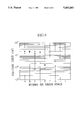
- FIG. 4 shows a relation between the 1st CLSs X and the 2nd CLS Y with a hatched region indicating the fixed-charge density of 1 ⁇ 10 11 /cm 2 or less;
- FIG. 5 shows a relation between five tubes of the heat treating furnaces with the different bores and fixed-charge densities under the condition of the TEST 2;
- FIG. 6 shows a relation between nine tubes of the heat treating furnaces with different bores and fixed-charge densities under the condition of the test for the prior art.
- FIG. 1 diagrammatically shows a longitudinal section of a horizontal heat treating furnace employed in a process for manufacturing MOS devices according to an embodiment of the present invention.
- the furnace 1 comprises a cylindrical tube 2 of quartz, a boat 3 placed in the tube 2 and retaining multiple silicon wafers 4 in vertical positions transversely against the longitudinal axis of the tube 2, a gas feed system 7 connected to one reduced end 2b of the tube 2a, a quartz cap 5 removably mounted to the other end 2a of the tube 2, a heater 6 surrounding the cylindrical wall of the tube 2.
- the boat 3 is put into the tube 2 through the one end 2a of the tube 2.
- the cap 5 has a small through-hole 5a which flows a gas outside the tube 2 and serves to make a gas flow laminar in the tube 2.
- a 1st CLS of an ambient gas is defined as a ratio of that flow rate to the area of the clearance between a silicon wafer 4 and the interior surface of the tube 2. More specifically, this clearance is a clearance between a silicon wafer 4 placed at the center of an array of silicon wafers 4 retained by the boat 3 and the interior surface of the tube 2.
- the purpose of the TEST 1 is to investigate a relation between the fixed-charge density and the 2nd CLS Y as a function of the 1st CLSs X.
- each silicon wafer 4 is a 5-inch diameter, the ⁇ 100> orientation, the p-type conduction and about 10- ⁇ cm resistivity.
- all of the silicon wafers 4 were cleaned and dried up.
- the cleaned silicon wafers 4 were immediately put into the horizontal heat treating furnaces.
- Each set of three silicon wafers 4 was heated at 1000° C. in the ambient of a wet oxygen for 1.5 hr.
- a gate oxide of a 500-nm thickness was grown on each silicon wafer 4.
- each set of three silicon wafers 4 was annealed in the ambient of nitrogen for 1 hr.
- the 1st CLSs X was respectively selected to be 20, 30, 40, 50 and 70 cm/min by sets of three silicon wafers 4.
- the 2nd CLS Y was selected to be particular values of 70-400 cm/min by a set of three silicon wafers 4.
- an aluminum electrode was deposited on each oxide film using a shadow mask by a vacuum evaporator.
- the oxide of back surface was removed.
- all of the silicon wafers 4 were heated at 400° C. in the ambient of a mixture gas of 3% hydrogen and 97% nitrogen for 30 min.
- MOS capacitors with 1.81 mm 2 gate area were fabricated.
- the C-V characteristics of each MOS capacitor was measured and fixed-charge densities at six points in the MOS capacitor were obtained. An average of the fixed-charge densities at the six points was determined as data of each silicon wafer.
- FIG. 3 shows a relation among the 1st CLSs X of the ambient gases of the oxidation and the annealing, the 2nd CLSs Y of the ambient gas at the step of taking the silicon wafers 4 out of the tube 2, and the fixed-charge densities in the silicon oxide film.
- FIG. 4 shows a relation between the 1st CLSs X and the 2nd CLS Y with a hatched region indicating the fixed-charge density of 1 ⁇ 10 11 /cm 2 or less.
- each plot represents an average of the fixed-charge densities of the three silicon wafers 4 with the same heat treatment conditions.
- the hatched region represents the 1st CLSs X and the 2nd CLS Y at which the fixed-charge density is 1 ⁇ 10 11 /cm 2 or less.
- FIG. 3 demonstrates that the fixed-charge density decreases as the 1st CLSs X and the 2nd CLS Y increase.
- FIGS. 3 and 4 demonstrate that when the 1st CLSs X is at least 30 cm/min and the 2nd CLS Y is at least 100 cm/min so that Y ⁇ -2.5 X+275, the fixed-charge densities in the silicon oxide film are 1 ⁇ 10 11 /cm 2 or less.
- the purpose of the TEST 2 is to investigate the repeatability of the present invention under the condition of the CLSs keeping the fixed-charge density of 1 ⁇ 10 11 /cm 2 or less.
- each silicon wafer 4 15 silicon wafers sliced from a silicon single crystal grown by the Czochralski method were prepared so that each silicon wafer 4 is a 5-inch diameter, the ⁇ 100> orientation, the p-type conduction and about 10- ⁇ cm resistivity. All of the silicon wafers 4 were cleaned and dried up. Subsequently, five sets of three silicon wafers 4 were immediately placed in five horizontal heat treating furnaces A, C, E, G and H with different bores of the tubes 2. Each set of three silicon wafers 4 was heated at 1000° C. in an ambient of wet oxygen for 1.5 hr. A gate oxide of a 500-nm thickness was grown on each silicon wafer 4. Successively, each set of three silicon wafers 4 was annealed in the ambient of nitrogen for 1 hr.
- the 1st CLSs X was 50 cm/min.
- the 2nd CLS Y was 175 cm/min.
- MOS capacitors with 1.81 mm 2 gate area were fabricated in the same manner as in the TEST 1.
- the C-V characteristics of each MOS capacitor was measured and fixed-charge densities at six points in the MOS capacitor were obtained. An average of the fixed-charge densities at the six points was determined as the data of each silicon wafer.
- FIG. 5 shows a relation between five tubes of the heat treaing furnace with the different bores and fixed-charge densities in silicon oxide films.
- the fixed-charge density is 1 ⁇ 10 11 /cm 2 or less
- all of the horizontal heat treating furnaces produce silicon oxide films of substantially the same fixed-charge density.
- the fixed-charge density is (8 ⁇ 2) ⁇ 10 10 /cm 2 which well matches the results of TEST 1 (see FIG. 3).
- the above embodiment controls the flow rates of the ambient gases by means of the gas feed system in order to control the 1st CLSs X and the 2nd CLS Y.
- dummy wafers with a diameter equal to or larger than the oxidized silicon wafers were placed at positions toward the opposite ends of the boat 3 in order to control the 1st CLSs X and the 2nd CLS Y by the ambient gases.
- the dummy wafer may be made of any suitable material, for example, quartz or silicon.
- An alternative embodiment of the present invention employed a heat treating furnace tube whose inner diameter is approximate the diameter of the semiconductor wafer so that the CLS increases sufficiently large with a small amount of the ambient gas. That is, it is useful to choose the bore of the tube as small as possible.
- the clearance as a element of the CLS is the area that insures the flow of the ambient gas in the tube.
- the temperature of the oxidation was 800°-900° C.
- the alternative embodiments had substantially the same results in respect to the fixed-charge density film as the embodiment described above in detail.
Landscapes
- Formation Of Insulating Films (AREA)
- Semiconductor Memories (AREA)
- Insulated Gate Type Field-Effect Transistor (AREA)
Priority Applications (1)
| Application Number | Priority Date | Filing Date | Title |
|---|---|---|---|
| US08/754,013 US5683513A (en) | 1992-12-17 | 1996-11-20 | Process and apparatus for manufacturing MOS device |
Applications Claiming Priority (2)
| Application Number | Priority Date | Filing Date | Title |
|---|---|---|---|
| JP4355269A JPH06188413A (ja) | 1992-12-17 | 1992-12-17 | Mos型半導体装置の製造方法 |
| JP4-355269 | 1992-12-17 |
Related Child Applications (1)
| Application Number | Title | Priority Date | Filing Date |
|---|---|---|---|
| US08/754,013 Division US5683513A (en) | 1992-12-17 | 1996-11-20 | Process and apparatus for manufacturing MOS device |
Publications (1)
| Publication Number | Publication Date |
|---|---|
| US5602061A true US5602061A (en) | 1997-02-11 |
Family
ID=18442951
Family Applications (2)
| Application Number | Title | Priority Date | Filing Date |
|---|---|---|---|
| US08/167,031 Expired - Fee Related US5602061A (en) | 1992-12-17 | 1993-12-16 | Process and apparatus for manufacturing MOS device |
| US08/754,013 Expired - Fee Related US5683513A (en) | 1992-12-17 | 1996-11-20 | Process and apparatus for manufacturing MOS device |
Family Applications After (1)
| Application Number | Title | Priority Date | Filing Date |
|---|---|---|---|
| US08/754,013 Expired - Fee Related US5683513A (en) | 1992-12-17 | 1996-11-20 | Process and apparatus for manufacturing MOS device |
Country Status (3)
| Country | Link |
|---|---|
| US (2) | US5602061A (fr) |
| EP (1) | EP0602995A3 (fr) |
| JP (1) | JPH06188413A (fr) |
Cited By (2)
| Publication number | Priority date | Publication date | Assignee | Title |
|---|---|---|---|---|
| US6283130B1 (en) | 1995-05-30 | 2001-09-04 | Anelva Corporation | Plasma cleaning method and placement area protector used in the method |
| US6683004B1 (en) * | 1999-11-25 | 2004-01-27 | Mitsubishi Denki Kabushiki Kaisha | Method of manufacturing a semiconductor device, and semiconductor device manufactured thereby |
Families Citing this family (14)
| Publication number | Priority date | Publication date | Assignee | Title |
|---|---|---|---|---|
| JP3042659B2 (ja) * | 1993-07-06 | 2000-05-15 | 信越半導体株式会社 | 半導体ウエーハの酸化方法 |
| JPH08264400A (ja) * | 1995-03-28 | 1996-10-11 | Mitsubishi Electric Corp | シリコン単結晶ウェハおよびその表面の熱酸化方法 |
| US6001182A (en) * | 1997-06-05 | 1999-12-14 | Vlsi Technology, Inc. | Waferless boat used as baffle during wafer processing |
| US7739381B2 (en) | 1998-03-11 | 2010-06-15 | Commvault Systems, Inc. | System and method for providing encryption in storage operations in a storage network, such as for use by application service providers that provide data storage services |
| JP2000174135A (ja) * | 1998-12-07 | 2000-06-23 | Mitsubishi Electric Corp | 半導体装置及びその製造方法 |
| JP2002043229A (ja) * | 2000-07-25 | 2002-02-08 | Hitachi Kokusai Electric Inc | 半導体製造装置 |
| CA2499073C (fr) | 2002-09-16 | 2013-07-23 | Commvault Systems, Inc. | Systeme et methode de copie auxiliaire a flux combine |
| US7592274B2 (en) | 2006-09-29 | 2009-09-22 | Oki Semiconductor Co., Ltd. | Method for fabricating semiconductor element |
| US8655914B2 (en) | 2006-10-17 | 2014-02-18 | Commvault Systems, Inc. | System and method for storage operation access security |
| US8434131B2 (en) | 2009-03-20 | 2013-04-30 | Commvault Systems, Inc. | Managing connections in a data storage system |
| US9904481B2 (en) | 2015-01-23 | 2018-02-27 | Commvault Systems, Inc. | Scalable auxiliary copy processing in a storage management system using media agent resources |
| US9898213B2 (en) | 2015-01-23 | 2018-02-20 | Commvault Systems, Inc. | Scalable auxiliary copy processing using media agent resources |
| US11010261B2 (en) | 2017-03-31 | 2021-05-18 | Commvault Systems, Inc. | Dynamically allocating streams during restoration of data |
| CN114823331B (zh) * | 2022-04-22 | 2023-03-03 | 江苏晟驰微电子有限公司 | 一种用于三极管器件制造的氮氢退火设备及其工艺 |
Citations (12)
| Publication number | Priority date | Publication date | Assignee | Title |
|---|---|---|---|---|
| US4139658A (en) * | 1976-06-23 | 1979-02-13 | Rca Corp. | Process for manufacturing a radiation hardened oxide |
| US4275094A (en) * | 1977-10-31 | 1981-06-23 | Fujitsu Limited | Process for high pressure oxidation of silicon |
| EP0031671A2 (fr) * | 1979-12-28 | 1981-07-08 | Fujitsu Limited | Procédé de dépôt chimique à partir de la phase vapeur de couches de verre au silicate |
| US4376796A (en) * | 1981-10-27 | 1983-03-15 | Thermco Products Corporation | Processing silicon wafers employing processing gas atmospheres of similar molecular weight |
| US4377605A (en) * | 1980-05-19 | 1983-03-22 | Fujitsu Limited | Method for forming an insulating layer on a polycrystalline silicon layer of a semiconductor device using a two-step thermal oxidation technique |
| DE3142548A1 (de) * | 1981-10-27 | 1983-05-05 | Siemens AG, 1000 Berlin und 8000 München | Verfahren zum herstellen von oxidschichten auf aus silizium oder anderem oxidierbarem material bestehenden substratscheiben in extrem trockener sauerstoffatmosphaere bzw. in sauerstoffatmosphaere mit chlorwasserstoffgas-zusaetzen |
| JPS618931A (ja) * | 1984-06-25 | 1986-01-16 | Hitachi Ltd | 半導体装置の製造方法 |
| JPS6123757A (ja) * | 1984-07-12 | 1986-02-01 | Toshiba Corp | 半導体ウエ−ハの酸化膜形成方法 |
| US4599247A (en) * | 1985-01-04 | 1986-07-08 | Texas Instruments Incorporated | Semiconductor processing facility for providing enhanced oxidation rate |
| JPH03224228A (ja) * | 1990-01-30 | 1991-10-03 | Fujitsu Ltd | 半導体装置の製造方法 |
| US5057463A (en) * | 1990-02-28 | 1991-10-15 | Sgs-Thomson Microelectronics, Inc. | Thin oxide structure and method |
| US5314846A (en) * | 1989-02-15 | 1994-05-24 | Atomel Products Corporation | Method for processing a semiconductor wafer |
Family Cites Families (2)
| Publication number | Priority date | Publication date | Assignee | Title |
|---|---|---|---|---|
| JPH0669050B2 (ja) * | 1984-06-25 | 1994-08-31 | 株式会社新川 | ボンデイング装置用加熱装置 |
| JP3087928B2 (ja) * | 1992-10-13 | 2000-09-18 | 横河電機株式会社 | 試験装置 |
-
1992
- 1992-12-17 JP JP4355269A patent/JPH06188413A/ja active Pending
-
1993
- 1993-12-16 US US08/167,031 patent/US5602061A/en not_active Expired - Fee Related
- 1993-12-17 EP EP93310226A patent/EP0602995A3/fr not_active Ceased
-
1996
- 1996-11-20 US US08/754,013 patent/US5683513A/en not_active Expired - Fee Related
Patent Citations (13)
| Publication number | Priority date | Publication date | Assignee | Title |
|---|---|---|---|---|
| US4139658A (en) * | 1976-06-23 | 1979-02-13 | Rca Corp. | Process for manufacturing a radiation hardened oxide |
| US4275094A (en) * | 1977-10-31 | 1981-06-23 | Fujitsu Limited | Process for high pressure oxidation of silicon |
| US4293590A (en) * | 1977-10-31 | 1981-10-06 | Fujitsu Limited | Process for high pressure oxidation of silicon |
| EP0031671A2 (fr) * | 1979-12-28 | 1981-07-08 | Fujitsu Limited | Procédé de dépôt chimique à partir de la phase vapeur de couches de verre au silicate |
| US4377605A (en) * | 1980-05-19 | 1983-03-22 | Fujitsu Limited | Method for forming an insulating layer on a polycrystalline silicon layer of a semiconductor device using a two-step thermal oxidation technique |
| DE3142548A1 (de) * | 1981-10-27 | 1983-05-05 | Siemens AG, 1000 Berlin und 8000 München | Verfahren zum herstellen von oxidschichten auf aus silizium oder anderem oxidierbarem material bestehenden substratscheiben in extrem trockener sauerstoffatmosphaere bzw. in sauerstoffatmosphaere mit chlorwasserstoffgas-zusaetzen |
| US4376796A (en) * | 1981-10-27 | 1983-03-15 | Thermco Products Corporation | Processing silicon wafers employing processing gas atmospheres of similar molecular weight |
| JPS618931A (ja) * | 1984-06-25 | 1986-01-16 | Hitachi Ltd | 半導体装置の製造方法 |
| JPS6123757A (ja) * | 1984-07-12 | 1986-02-01 | Toshiba Corp | 半導体ウエ−ハの酸化膜形成方法 |
| US4599247A (en) * | 1985-01-04 | 1986-07-08 | Texas Instruments Incorporated | Semiconductor processing facility for providing enhanced oxidation rate |
| US5314846A (en) * | 1989-02-15 | 1994-05-24 | Atomel Products Corporation | Method for processing a semiconductor wafer |
| JPH03224228A (ja) * | 1990-01-30 | 1991-10-03 | Fujitsu Ltd | 半導体装置の製造方法 |
| US5057463A (en) * | 1990-02-28 | 1991-10-15 | Sgs-Thomson Microelectronics, Inc. | Thin oxide structure and method |
Non-Patent Citations (14)
| Title |
|---|
| Ara Philipossian et al., "Nonideal Flow Behavior Analysis of Atmospheric Thermal Silicon Oxidation Reactors by the Residence Time Distribution Technique", Journal of the Electrochemical Society, vol. 138, No. 8, pp. 2451-2459, Aug. 1991. |
| Ara Philipossian et al., Nonideal Flow Behavior Analysis of Atmospheric Thermal Silicon Oxidation Reactors by the Residence Time Distribution Technique , Journal of the Electrochemical Society, vol. 138, No. 8, pp. 2451 2459, Aug. 1991. * |
| Bruce E. Deal et al., "Characteristics of the Surface-State Charge (Qss) of Thermally Oxidized Silicon", J. Electrochem. Soc.: SOLID STATE SCIENCE, Mar. 1967, pp. 266-273. |
| Bruce E. Deal et al., Characteristics of the Surface State Charge (Q ss ) of Thermally Oxidized Silicon , J. Electrochem. Soc.: SOLID STATE SCIENCE, Mar. 1967, pp. 266 273. * |
| Bruce E. Deal, "Standardized Terminology for Oxide Charges Associated With Thermally Oxidized Silicon", IEEE Transactions on Electron Devices, vol. ED-27, No. 3, Mar. 1980, pp. 606-608. |
| Bruce E. Deal, Standardized Terminology for Oxide Charges Associated With Thermally Oxidized Silicon , IEEE Transactions on Electron Devices, vol. ED 27, No. 3, Mar. 1980, pp. 606 608. * |
| F. Montillo et al., "High-Temperature Annealing of Oxidized Silicon Surfaces", Growth of Semiconductor Superlattice, vol. 118, No. 9, pp. 1463-1468. |
| F. Montillo et al., High Temperature Annealing of Oxidized Silicon Surfaces , Growth of Semiconductor Superlattice, vol. 118, No. 9, pp. 1463 1468. * |
| Institute of Environmental Sciences, "Contamination Control, Computer Applications--CC-related", 1992 Proceedings, vol. 1, pp. 352-361, May 1992. |
| Institute of Environmental Sciences, Contamination Control, Computer Applications CC related , 1992 Proceedings, vol. 1, pp. 352 361, May 1992. * |
| S. P. Tray et al., "Thin Gate and Poly Oxides by High Pressure Silicon Oxidation", 1046 Journal of the Electrochemical Society, No. 6, pp. 1484-1488, Jun. 1987. |
| S. P. Tray et al., Thin Gate and Poly Oxides by High Pressure Silicon Oxidation , 1046 Journal of the Electrochemical Society, No. 6, pp. 1484 1488, Jun. 1987. * |
| V. Nayar et al., "Optimisation of Furnace Oxidation of Si With Respect to Negative Bias Stress Instability", Microelectric Engineering, vol. 22, pp. 47-50, 1993. |
| V. Nayar et al., Optimisation of Furnace Oxidation of Si With Respect to Negative Bias Stress Instability , Microelectric Engineering, vol. 22, pp. 47 50, 1993. * |
Cited By (4)
| Publication number | Priority date | Publication date | Assignee | Title |
|---|---|---|---|---|
| US6283130B1 (en) | 1995-05-30 | 2001-09-04 | Anelva Corporation | Plasma cleaning method and placement area protector used in the method |
| US20010042554A1 (en) * | 1995-05-30 | 2001-11-22 | Anelva Corporation | Plasma cleaning method and placement area protector used in the method |
| US6769439B2 (en) | 1995-05-30 | 2004-08-03 | Anelva Corporation | Plasma cleaning method and placement area protector used in the method |
| US6683004B1 (en) * | 1999-11-25 | 2004-01-27 | Mitsubishi Denki Kabushiki Kaisha | Method of manufacturing a semiconductor device, and semiconductor device manufactured thereby |
Also Published As
| Publication number | Publication date |
|---|---|
| JPH06188413A (ja) | 1994-07-08 |
| EP0602995A3 (fr) | 1995-09-20 |
| EP0602995A2 (fr) | 1994-06-22 |
| US5683513A (en) | 1997-11-04 |
Similar Documents
| Publication | Publication Date | Title |
|---|---|---|
| US5602061A (en) | Process and apparatus for manufacturing MOS device | |
| EP0521644B1 (fr) | Procédé de fabrication d'un film en polysilicium | |
| US3964085A (en) | Method for fabricating multilayer insulator-semiconductor memory apparatus | |
| US4493142A (en) | III-V Based semiconductor devices and a process for fabrication | |
| US6187100B1 (en) | Semiconductor device and production thereof | |
| US3165811A (en) | Process of epitaxial vapor deposition with subsequent diffusion into the epitaxial layer | |
| JPH01204435A (ja) | 集積回路の製造方法 | |
| US4752590A (en) | Method of producing SOI devices | |
| JPH0766256A (ja) | シリコン結晶中の水素濃度測定方法, 低水素濃度シリコン結晶及びその製造方法 | |
| US5435264A (en) | Process for forming epitaxial BaF2 on GaAs | |
| US4818711A (en) | High quality oxide on an ion implanted polysilicon surface | |
| JP2764049B2 (ja) | 化合物半導体装置の製造方法、化合物半導体装置及び電界効果トランジスタ | |
| US5066610A (en) | Capping technique for zone-melting recrystallization of insulated semiconductor films | |
| US4489103A (en) | SIPOS Deposition method | |
| US5932006A (en) | BaF2 /GaAs electronic components | |
| US5620932A (en) | Method of oxidizing a semiconductor wafer | |
| US4889583A (en) | Capping technique for zone-melting recrystallization of insulated semiconductor films | |
| Chen et al. | Topographic imperfections in zone melting recrystallized Si films on SiO2 | |
| US4353936A (en) | Method of manufacturing semiconductor device | |
| KR100558287B1 (ko) | 단전자 소자, 그 제조 방법 및 단전자 소자와 mos트랜지스터를 동시에 형성하는 제조방법 | |
| KR930012117B1 (ko) | 표면적이 증대된 전하저장전극 제조방법 | |
| Kunii et al. | Effects of substrate-surface cleaning on solid phase epitaxial Si films | |
| JPH1140763A (ja) | 半導体装置の製造方法 | |
| JP2757257B2 (ja) | 酸化物超伝導薄膜の形成方法 | |
| JP2617485B2 (ja) | ▲iii▼−v化合物半導体の熱処理方法 |
Legal Events
| Date | Code | Title | Description |
|---|---|---|---|
| AS | Assignment |
Owner name: SHIN-ETSU HANDOTAI CO., LTD., JAPAN Free format text: ASSIGNMENT OF ASSIGNORS INTEREST;ASSIGNOR:FUJIMAKI, NOBUYOSHI;REEL/FRAME:006880/0635 Effective date: 19931224 |
|
| REMI | Maintenance fee reminder mailed | ||
| LAPS | Lapse for failure to pay maintenance fees | ||
| FP | Lapsed due to failure to pay maintenance fee |
Effective date: 20010211 |
|
| STCH | Information on status: patent discontinuation |
Free format text: PATENT EXPIRED DUE TO NONPAYMENT OF MAINTENANCE FEES UNDER 37 CFR 1.362 |