US5740040A - Electric power steering apparatus with enhanced road feel - Google Patents
Electric power steering apparatus with enhanced road feel Download PDFInfo
- Publication number
- US5740040A US5740040A US08/563,585 US56358595A US5740040A US 5740040 A US5740040 A US 5740040A US 56358595 A US56358595 A US 56358595A US 5740040 A US5740040 A US 5740040A
- Authority
- US
- United States
- Prior art keywords
- motor
- angular velocity
- motor angular
- estimate
- current
- Prior art date
- Legal status (The legal status is an assumption and is not a legal conclusion. Google has not performed a legal analysis and makes no representation as to the accuracy of the status listed.)
- Expired - Lifetime
Links
Images




Classifications
-
- B—PERFORMING OPERATIONS; TRANSPORTING
- B62—LAND VEHICLES FOR TRAVELLING OTHERWISE THAN ON RAILS
- B62D—MOTOR VEHICLES; TRAILERS
- B62D6/00—Arrangements for automatically controlling steering depending on driving conditions sensed and responded to, e.g. control circuits
- B62D6/08—Arrangements for automatically controlling steering depending on driving conditions sensed and responded to, e.g. control circuits responsive only to driver input torque
-
- G—PHYSICS
- G01—MEASURING; TESTING
- G01P—MEASURING LINEAR OR ANGULAR SPEED, ACCELERATION, DECELERATION, OR SHOCK; INDICATING PRESENCE, ABSENCE, OR DIRECTION, OF MOVEMENT
- G01P3/00—Measuring linear or angular speed; Measuring differences of linear or angular speeds
- G01P3/42—Devices characterised by the use of electric or magnetic means
- G01P3/44—Devices characterised by the use of electric or magnetic means for measuring angular speed
-
- B—PERFORMING OPERATIONS; TRANSPORTING
- B62—LAND VEHICLES FOR TRAVELLING OTHERWISE THAN ON RAILS
- B62D—MOTOR VEHICLES; TRAILERS
- B62D5/00—Power-assisted or power-driven steering
- B62D5/04—Power-assisted or power-driven steering electrical, e.g. using an electric servo-motor connected to, or forming part of, the steering gear
- B62D5/0457—Power-assisted or power-driven steering electrical, e.g. using an electric servo-motor connected to, or forming part of, the steering gear characterised by control features of the drive means as such
- B62D5/046—Controlling the motor
- B62D5/0463—Controlling the motor calculating assisting torque from the motor based on driver input
-
- B—PERFORMING OPERATIONS; TRANSPORTING
- B62—LAND VEHICLES FOR TRAVELLING OTHERWISE THAN ON RAILS
- B62D—MOTOR VEHICLES; TRAILERS
- B62D5/00—Power-assisted or power-driven steering
- B62D5/04—Power-assisted or power-driven steering electrical, e.g. using an electric servo-motor connected to, or forming part of, the steering gear
- B62D5/0457—Power-assisted or power-driven steering electrical, e.g. using an electric servo-motor connected to, or forming part of, the steering gear characterised by control features of the drive means as such
- B62D5/046—Controlling the motor
- B62D5/0466—Controlling the motor for returning the steering wheel to neutral position
-
- B—PERFORMING OPERATIONS; TRANSPORTING
- B62—LAND VEHICLES FOR TRAVELLING OTHERWISE THAN ON RAILS
- B62D—MOTOR VEHICLES; TRAILERS
- B62D5/00—Power-assisted or power-driven steering
- B62D5/04—Power-assisted or power-driven steering electrical, e.g. using an electric servo-motor connected to, or forming part of, the steering gear
- B62D5/0457—Power-assisted or power-driven steering electrical, e.g. using an electric servo-motor connected to, or forming part of, the steering gear characterised by control features of the drive means as such
- B62D5/046—Controlling the motor
- B62D5/0472—Controlling the motor for damping vibrations
Definitions
- the present invention relates to a power steering wherein steering assisting torque is generated by a motor.
- an electrically-operated power steering system is provided with a torque sensor for the steering torque of a steering system and a vehicle speed sensor for detecting vehicle speed, to control the assist torque for a motor coupled to the steering system on the basis of the output data of these sensors.
- a torque sensor for the steering torque of a steering system and a vehicle speed sensor for detecting vehicle speed, to control the assist torque for a motor coupled to the steering system on the basis of the output data of these sensors.
- a method for compensating the inertia, viscosity or the like of a steering system on the basis of the angular velocity or angular acceleration of a motor has been proposed in addition to controlling the assist torque of a motor.
- a sensor for detecting the angle or angular velocity of a motor is provided.
- a method for obtaining an angular-velocity signal by estimating the induced voltage of a motor has been proposed.
- FIG. 41 shows an electrically-operated power steering disclosed in Japanese Patent Laid-Open Publication No. 4-8190.
- a motor 1 for assisting the steering is coupled to the steering system, while the steering torque of the steering system is detected in a torque sensor 2 and the vehicle speed is detected in a vehicle speed sensor 3.
- the current flowing through a motor 1 for assisting the steering is detected in motor current detection means 4 and the voltage applied to a motor 1 is detected in motor-applied voltage detection means 5.
- the motor current for statically assisting the steering torque is calculated in steering-force assist current calculation means 9.
- the steering torque Vt detected by the torque sensor 2 and the vehicle speed Vs detected by the vehicle speed sensor 3 are input as data for calculation to the steering-force assist current calculation means 9 and a steering-force assist current target Is is output as the calculated result therefrom.
- the current flowing through the motor 1 is controlled by motor current control means 10, to which a motor current target Ia* and the value of motor current Ia sns detected by the motor current detection means 4 are input and from which a motor drive signal is output to the motor 1 on the basis of input current.
- the angular velocity of the motor 1 is calculated by motor angular velocity calculation means 11, to which the detected value of motor-applied voltage Va sns and the detected value of motor current Ia sns are input and from which the motor angular-velocity estimate ⁇ calculated from these detected values is output.
- the motor angular acceleration estimate ⁇ calculated by motor angular velocity calculation means 11 is input and the motor angular acceleration estimate d ⁇ /dt obtained by differentiating this estimate ⁇ is output therefrom.
- a value of motor current Id required for compensating the viscous friction of the steering system is calculated by viscous-friction compensating current calculation means 14, to which the motor angle estimate ⁇ and the motor angular velocity estimate ⁇ described later as well as the vehicle speed Vs detected by a vehicle speed sensor 3 are input and from which a viscous-friction compensating motor current target Id calculated from these input values is output.
- Inertia compensating current calculation means 15 for calculating the motor current for compensating the inertial moment of the steering system calculates and outputs inertia compensating motor current target Ij on the basis of the motor angular-acceleration estimate d ⁇ /dt.
- motor angle calculation means 16 calculates a motor angle estimate ⁇ by integration and outputs the obtained estimate.
- a steering wheel is steered by a driver, then a steering torque is generated in the steering system and detected by a torque sensor 2, when the steering-force assist current calculation means 9 calculates a steering force assist current target Is, e.g., as shown in FIG. 42, on the basis of the vehicle speed Vs input from the vehicle speed sensor 3 and the steering torque Vt input from the torque sensor 2 and the calculated result is given to motor current control means 10 as a motor current target Ia*.
- the motor current control means 10 performs such a feedback control that the detected value Ia sns of motor current may coincide with the motor current target Ia* and further drives the motor 1. Once the motor 1 is driven, the voltage applied to the motor 1 is detected by motor-applied voltage detection means 5 and the detected value is given as detected value Va sns of motor-applied voltage to motor angular-velocity calculation means 11.
- a motor angular velocity estimate ⁇ is calculated from the detected calculates from the motor angular acceleration estimate d ⁇ /dt inertia compensating current target Ij, effective in alleviating the feeling of inertia to make the steering force heavier under influence of the inertial moment of the rotor in a motor 1 especially at the time of reversal in steering direction, and adds the target obtained to the steering-force assist current target Is.
- the motor current target Ia* is found and given to motor current control means 10, so that the motor current is controlled in the following similar procedure.
- motor angular velocity calculation means 16 on neglecting the transient term based on value Va sns of motor-applied voltage and from the detected value Ia sns of motor current and given to motor angular acceleration calculation means 12, motor angular velocity calculation means 16 and viscous-friction compensating current calculation means 14.
- motor angular acceleration calculation means 12 a motor angular acceleration estimate d ⁇ /dt is determined by differentiating the motor angular velocity estimate ⁇ and given to inertia compensating current calculating means 15.
- the motor angle ⁇ is determined by integrating the motor angular velocity estimate ⁇ and given to viscous-friction compensating current calculating means 14.
- viscous-friction compensating current calculating means 14 a feeling of viscosity is imparted to steering feel from the vehicle speed Vs, the motor angular velocity estimate ⁇ and the motor angle estimate ⁇ and moreover a viscous-friction compensating current target id, effective for enhancing the convergence of steering wheel return likely to worsen particularly during high-speed driving, is calculated. Then, this target Id is subtracted from the steering-force assist current target Is in an adder.
- Inertia compensating current calculation means 15 the armature inductance La, Va can be expressed in the following equation (1):
- the motor angular velocity can be estimated by expressing Eq. (3) as Eq. (4).
- Va sns Detected value of motor applied voltage
- Ia sns Detected value of motor current.
- the relation between Va and Ia is nearly as shown in FIG. 44 and repeats a transient phenomenon at each switching between power running and regenerative running.
- the PWM carrier period is set to be sufficiently short for the electric time constant of a motor 1, so that Ia can be regarded as DC but Va becomes a square wave.
- the motor angular velocity ⁇ in accordance with Eq. (4), it is necessary to remove the square wave component of Va and obtain the time average of Id.
- motor angular velocity calculation means 11 After sampling the detected value of square-waved motor-applied voltage, the square wave component is removed by using a digital filter and ⁇ is calculated in according with Eq. (4).
- a motor is PWM-driven to suppress the heating of a switching element for motor drive control and the PWM carrier frequency is set to around 20 kHz outside the audible frequency band to prevent noise from occurring in the motor drive as described above.
- the motor angular velocity calculation means to be implemented by software processing and for the square wave component of the motor-applied voltage Va to be removed by using a digital filter, the sample frequency must be set to a very high level to accurately calculate the motor angular velocity ⁇ and consequently the software processing is heavily overloaded, thereby leading to the problem of having to use an expensive CPU with high processing speed.
- the armature resistance Ra includes wiring resistance between the motor and the controller and contact resistance of a connector and the variation in the armature resistance of individual motors is large. Furthermore, the armature resistance Ra varies under the influence of temperature, such as heating in the flow of a heavy current. Thus, errors are naturally considered to be contained in armature resistance.
- ⁇ Ra be the error between the Ra used for calculation in accordance with Eq. (4) and the actual Ra
- the motor angular velocity ⁇ can be expressed in the following equation (5).
- An electric power steering apparatus comprises: a motor connected to the steering system; PWM control means for driving and controlling said motor on the basis of a PWM modulated control signal; motor-applied voltage detection means having a low pass characteristic for converting the detected voltage applied to said motor to a predetermined level after removing said PWM carrier frequency component therefrom with the aide of the low-pass characteristic and outputting the resultant voltage wherein the cutoff frequency set below the PWM carrier frequency contained in said control signal; angular velocity estimation means for estimating the angular velocity of said motor on the basis of the detected motor-applied voltage; and current value calculation means for calculating the current target of said motor on the estimated result of angular velocity.
- An electric power steering apparatus comprises: a motor connected to the steering system; PWM control means for driving and controlling said motor on the basis of a PWM modulated control signal; motor terminal voltage detection means having a low-pass characteristic for converting the detected terminal voltage of said motor to a predetermined level after removing said PWM carrier frequency component therefrom with the aide of the low-pass characteristic and outputting the resultant voltage wherein the cutoff frequency set below the PWM carrier frequency contained in said control signal; angular velocity estimation means for estimating the angular velocity of said motor on the basis of the detected motor terminal voltage; and current value calculation means for calculating the current target of said motor on the estimated result of angular velocity.
- the motor angular velocity estimate is clipped below a predetermined value in accordance with a current through said motor.
- the motor angular velocity estimate is clipped below a predetermined value in accordance with the steering torque.
- the motor angular velocity estimate is clipped to 0 if the calculated result of motor angular acceleration is below a predetermined value.
- the motor angular velocity estimate is subjected to a high-pass filtering if said PWM carrier frequency is above a predetermined frequency.
- the motor angular acceleration is estimated by differentiating the motor angular velocity estimate.
- the differential processing has a band pass characteristic.
- the motor angular velocity estimate is subjected to a low-pass filtering having a cutoff frequency nearly equal to the high-region cutoff frequency of the band pass characteristics at the time of differential processing.
- the motor angular acceleration estimate is clipped to 0 if the calculated result thereof is below a predetermined value.
- the motor angular velocity estimate is positively fed back to the steering control system and, in accordance with the positive feedback, the motor current passing is clipped below a predetermined value based on the friction of the steering system.
- the motor current value or the positive feedback gain of motor angular velocity is changed depending on at least either one of said motor angular velocity estimate and said vehicle speed.
- differentiation means for increasing the motor current flowing through in accordance with the positive feedback of the motor angular velocity estimate at the rising time is provided.
- steering control based on the angular velocity is performed by the negative feedback of the motor angular velocity estimate.
- the negative feedback gain of said motor angular velocity estimate is changed depending on at least either one of said motor angular velocity estimate and said vehicle speed.
- steering control based on said motor angular acceleration is performed by the positive feedback of said angular acceleration estimate.
- the positive feedback gain of said motor angular acceleration estimate is changed depending on at least either one of said motor angular acceleration estimate and said vehicle speed.
- FIG. 1 is a hardware block diagram of a control according to one embodiment of the present invention
- FIG. 2 is a software block diagram of a control according to one embodiment of the present invention.
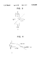
- FIG. 3 is a graph showing the DC characteristic of a motor-applied voltage detection circuit in a control according to one embodiment of the present invention
- FIG. 4 is a graph showing the frequency characteristic of a motor-applied voltage detection circuit in a control according to one embodiment of the present invention
- FIG. 5 is a graph illustrating a method for setting the cutoff frequency in a motor-applied voltage detection circuit or a motor terminal voltage detection circuit in a control according to one embodiment of the present invention
- FIG. 6 is a flowchart illustrating the operation of motor angular velocity calculation means in a control according to one embodiment of the present invention
- FIG. 7 is a graph illustrating the relation between the coefficient for correcting a motor angular velocity estimate and the motor current in a control according to one embodiment of the present invention.
- FIG. 8 is a graph illustrating the relation between motor current and motor angular velocity in a DC motor
- FIG. 9 is a flowchart illustrating the operation of motor angular acceleration calculation means in a control according to one embodiment of the present invention.
- FIG. 10 is a block diagram illustrating the operation of motor angular acceleration calculation means in a control according to one embodiment of the present invention.
- FIG. 11 is a graph showing the frequency characteristic of motor angular acceleration calculation means in a control according to one embodiment of the present invention.
- FIG. 12 is another graph showing the frequency characteristic of motor angular acceleration calculation means in a control according to one embodiment of the present invention.
- FIG. 13 is a flowchart illustrating the operation of Coulomb-friction compensation current calculation means in a control according to one embodiment of the present invention
- FIG. 14 is a graph illustrating the relation between the motor angular velocity estimate and the vehicle speed and the Coulomb-friction compensation current in a control according to one embodiment of the present invention.
- FIG. 15 is a flowchart illustrating the operation of viscous-friction compensation current calculation means in a control according to one embodiment of the present invention.
- FIG. 16 is a graph illustrating the relation between the motor angular velocity estimate and the vehicle speed and the viscous-friction compensation current in a control according to one embodiment of the present invention
- FIG. 17 is a flowchart illustrating the operation of inertia compensation current calculation means in a control according to one embodiment of the present invention.
- FIG. 18 is a graph illustrating the relation between the motor angular velocity estimate and the vehicle speed and the inertia compensation current in a control according to one embodiment of the present invention.
- FIG. 19 is a graph illustrating the relation between the coefficient for correcting the motor angular velocity estimate and the steering torque in a control according to another embodiment of the present invention.
- FIG. 20 is a flowchart illustrating a method for correcting the motor angular velocity estimate in a control according to a third embodiment of the present invention.
- FIG. 21 is a graph illustrating the relation between the threshold for correcting the motor angular velocity estimate and the motor current in a control according to a third embodiment of the present invention.
- FIG. 22 is a flowchart illustrating a method for correcting the motor angular velocity estimate in a control according to a fourth embodiment of the present invention.
- FIG. 23 is a block diagram illustrating the relation between means for correcting the motor angular velocity estimate and means for calculating the motor control current in a control according to a fifth embodiment of the present invention.
- FIG. 24 is a block diagram illustrating the relation between means for correcting the motor angular velocity estimate and motor angular acceleration calculation means in a control according to a sixth embodiment of the present invention.
- FIGS. 25(a) and 25(b) are a set of graphs illustrating the relation between means for correcting the motor angular velocity estimate and motor angular acceleration calculation means in a control according to a seventh embodiment of the present invention.
- FIG. 26 is a block diagram illustrating the relation between means for correcting the motor angular velocity estimate and motor angular acceleration calculation means and means for calculating the motor control current in a control according to a seventh embodiment of the present invention
- FIG. 27 is a graph illustrating a method for correcting the motor angular acceleration estimate in a control according to an eighth embodiment of the present invention.
- FIG. 28 is a graph illustrating the relation between the motor angular velocity estimate and the Coulomb-friction compensating current in a control according to a ninth embodiment of the present invention.
- FIG. 29 is a graph illustrating the relation between the motor angular velocity estimate and the Coulomb-friction compensating current in a control according to a tenth embodiment of the present invention.
- FIG. 30 is another graph illustrating the relation between the motor angular velocity estimate and the Coulomb-friction compensating current in a control according to a tenth embodiment of the present invention.
- FIG. 31 is a block diagram illustrating a method for compensating the static friction in a control according to an eleventh embodiment of the present invention.
- FIG. 32 is a flowchart illustrating a method for compensating the static friction in a control according to an eleventh embodiment of the present invention.
- FIG. 33 is a graph illustrating the relation between the differential value of motor angular velocity estimate and the static friction compensating current in a control according to an eleventh embodiment of the present invention.
- FIG. 34 is a block diagram illustrating another method for compensating the static friction in a control according to an eleventh embodiment of the present invention.
- FIG. 35 is a graph illustrating the relation between the motor angular velocity estimate and the viscous-friction compensating current in a control according to a twelfth embodiment of the present invention.
- FIG. 36 is a graph illustrating the relation between the motor angular acceleration estimate and the viscous-friction compensating current in a control according to a thirteenth embodiment of the present invention.
- FIG. 37 is a hardware block diagram of a control according to a fourteenth embodiment of the present invention.
- FIG. 38 is a graph showing the DC characteristic of a motor terminal voltage detection circuit in a control according to a fourteenth embodiment of the present invention.
- FIG. 39 is a graph showing the frequency characteristic of a motor terminal voltage detection circuit in a control according to a fourteenth embodiment of the present invention.
- FIG. 40 is a flowchart illustrating a method for calculating the motor-applied voltage in a control according to a fourteenth embodiment of the present invention.
- FIG. 41 is a block diagram showing the arrangement of a conventional control
- FIG. 42 is a graph illustrating the relation between the steering torque and the steering assist current for the present invention and a conventional control
- FIG. 43 is an equivalent circuit diagram of a DC motor armature
- FIG. 44 is a waveform graph showing the relation between the motor-applied voltage and the motor current in the PWI drive of a DC motor.
- FIG. 1 is a structural view of a controller section of an electrically operated power steering apparatus in accordance with an Embodiment 1 of the present invention.
- Output of a toque sensor 2 is input to the A/D convertor 8f described later via a torque sensor input I/F 2a for DC amplification an phase compensation.
- Output of a vehicle speed sensor 3 is input to the input/output port 8e via a vehicle sensor input I/F 3a.
- a current detecting resistor 4a Current through a motor 1 is converted with a current detecting resistor 4a to a predetermined voltage in a motor current detection circuit 4, comprising a sample/hold circuit 4b for sampling the voltage between both ends of the current detecting resistor 4a during the power running time, holding it during the regenerative running time and amplifying the held voltage in an amplification circuit 4c.
- the motor-applied voltage detection circuit 5 comprises an OP amplifier 5j and filter constants composed of resistors 5a-5g and capacitors 5h-5i.
- An H-shaped bridge circuit 7 for passing current for right-handed and left-handed rotations comprises four bridge-connected power MOSFETs 7a-7d to be driven by FET drivers 6a-6d.
- a microcomputer 8 for outputting a drive signal to H-shaped bridge drive circuit 6 comprises: a CPU 8a; a ROM 8b for storing programs and the like; a RAM 8c for temporarily holding data and the like; a pulse width modulator 8d connected to FET drivers 6a, 6c for generating a pulse to drive the motor 1; I/O port 8e connected to FET drivers 6b, 6d and connected via vehicle speed sensor input I/F 3a to the vehicle speed sensor 3; an A/D convertor 8f connected to the output of the motor current detection circuit 4 and that of the motor-applied voltage detection circuit 5 and connected via a torque sensor input I/F 2a to the torque sensor 2; and a timer 8g to be used for managing the control period or the like.
- FIG. 2 is an S/W block diagram of the steering control processed by the CPU 8a.
- steering force assist current calculation means 9 for calculating the motor current used for statically assisting the steering torque
- the steering torque Vt detected by the torque sensor 2 and the vehicle speed Vs detected by the vehicle speed sensor 3 are input and the steering force assist current target Is is output therefrom.
- the motor angular-velocity estimate ⁇ calculated by motor angular-velocity calculation means 11 is input and the motor angular-acceleration estimate d ⁇ /dt obtained by differentiating this motor angular-velocity estimate ⁇ is output therefrom.
- the motor angular-velocity estimate ⁇ and the vehicle speed Vs detected by the vehicle speed sensor 3 are input and a Coulomb-friction compensating current target Ic is output therefrom on the basis of these input values.
- To inertia-compensating current calculation means 15 for calculating the motor current for compensating the inertial moment of the steering system the motor angular-acceleration estimate d ⁇ /dt is input and an inertia compensating motor current target Ij is output therefrom.
- FIGS. 3 and 4 show the DC characteristic and the frequency characteristic of a motor-applied voltage detection circuit 5, respectively.
- FIG. 5 illustrates a method for setting the cutoff frequency of a motor-applied voltage detection circuit 5.
- FIG. 6 is a flowchart to illustrate the operation of motor angular velocity calculation means 11, while FIG. 7 illustrates a coefficient K1 for correcting the motor angular velocity estimate ⁇ .
- FIG. 8 illustrates the relation between the motor current Ia and the motor angular-velocity ⁇ m.
- FIG. 9 is a flowchart to illustrate the operation of motor angular acceleration calculation means 12.
- FIG. 10 is a block diagram representing the function of motor angular acceleration calculation means 12.
- FIGS. 11 and 12 indicate the frequency characteristics thereof.
- FIG. 13 is a flowchart to illustrate the operation of Coulomb-friction compensating current calculation means 13.
- FIG. 14 illustrates the relation among the motor angular velocity estimate ⁇ and the vehicle speed Vs and the Coulomb-friction compensating current Ic.
- FIG. 15 is a flowchart to illustrate the operation of viscous-friction compensating current calculation means 14.
- FIG. 16 illustrates the relation among the motor angular velocity estimate ⁇ and the vehicle speed Vs and the viscous-friction compensating current Id.
- FIG. 17 is a flowchart to illustrate the operation of inertia-compensating current calculation means 15.
- FIG. 18 illustrates the relation among the motor angular acceleration estimate d ⁇ /dt and the vehicle speed Vs and the inertia-compensating current Ij.
- the FET drivers 6b and 6c turn OFF the power MOSFET's 7b and 7c
- the FET driver 6d turns ON the power MOSFET 7d
- the FET driver 6a PWM-drives the power MOSFET 7a at a predetermined duty ratio.
- motor current Ia flows along the path indicated by the power running or the regenerative running in FIG. 1, respectively.
- the motor current Ia is first converted into voltage by the current detecting resistor 4a.
- the motor current Ia does not flow through the current detecting resistor 4a as shown in FIG. 1.
- the held voltage is amplified at a predetermined gain in the amplification circuit 4c, input to the A/D convertor 8f in the microcomputer 8 and digitally converted.
- the digitally converted current is detected by the microcomputer 8.
- the motor-applied voltage detection circuit 5 removes the square component appearing in the motor-applied voltage Va in association with the PWM drive and moreover inputs the resultant component to the A/D convertor 8f after converting it to a predetermined voltage level so that input to A/D convertor 8f becomes possible.
- Va sns is equal to voltage obtained by attaching the first-order retardation characteristic of a time constant C1 ⁇ R2 to the R2/R1 divided voltage of Va and further adding the result to a DC bias voltage V1. That is, the DC characteristic and the frequency characteristic become as shown in FIG. 3 and in FIG. respectively.
- V1 at the center (e.g., 2.5V) of the input voltage range (e.g., 0 to 5V) of the A/D convertor 8f.
- R2/R1 is set in such a manner that the voltage range of Va (e.g., -12 to 12V) is changed in level to the input voltage range (e.g., 0 to 5V) of the A/D convertor 8f.
- Va e.g., -12 to 12V
- Steering -force assist current target is calculated on the basis of steering torque and vehicle speed
- motor angular velocity estimate is calculated from the detected value of motor-applied voltage and that of motor current
- a motor angular acceleration is calculated from the calculated result.
- each compensating current target is calculated from the calculated motor angular velocity estimate and motor angular acceleration estimate
- motor current target is determined by adding the aforesaid steering-force assist current target and the aforesaid respective compensating current targets together from these calculated results and the feedback control of this motor current target is performed.
- steering-force assist current calculation means 9 and current control means 10 have the same functions as those in a conventional apparatus and thus the description thereof will be omitted.
- motor angular velocity calculation means 11 calculates a motor angular velocity estimate ⁇ from the detected value of motor-applied voltage Va sns and that of motor current Ia sns in accordance with Eq. (4). Referring to the flowchart of FIG. 6, this procedure will be described.
- the A/D converted data of the detected value of motor-applied voltage Va sns and that of motor current Ia sns in S61 is read and the constant data of armature resistance Ra and motor-induced voltage constant Ke is read from the ROM in S62.
- the coefficient K1 is determined from the detected value of motor current Ia sns read in S61.
- a motor angular velocity estimate ⁇ is calculated from Eq. (4) and the K1, is determined in S63, and Eq.(10) below, and the obtained estimate ⁇ is stored in the RAM 8c.
- the Ia sns -K1 table and K1 will be described in detail.
- the error in motor angular velocity estimate ⁇ attributable to the error in armature resistance Ra is proportional to the motor current Ia and increases with an increase in motor current Ia as shown by Eq. (5). That is, the offset of motor angular velocity estimate ⁇ increases with an increase in motor current Ia.
- the voltage applied to a motor is constant, however, there is a relation between the motor current Ia and the motor angular velocity ⁇ m such that the motor angular velocity ⁇ m decreases with an increase in motor current Ia as shown in FIG. 8.
- Eq. (4), K1 and the detected value of motor current Ia sns are employed in calculating ⁇ but the motor current target Ia* may be employed in place of the detected value of motor current Ia sns if the response of current control means 10 can be regarded as being speedy enough. Then, there is an advantage that the calculated ⁇ is not affected by the noise contained in the detected value of motor current Ia sns .
- the square wave component is removed from the motor-applied voltage in the motor-applied voltage detection circuit 5 and accordingly further software calculation becomes simple and the sampling frequency can be also set to a lower value.
- the offset of motor angular velocity estimate ⁇ caused by an error in armature resistance Ra can also be simply and effectively removed.
- the motor angular acceleration calculation means 12 calculates a motor angular acceleration estimate d ⁇ /dt from the motor angular velocity estimate ⁇ calculated in motor angular velocity calculation means 11. This calculation procedure will be described referring to the flowchart of FIG. 9 and the block diagram of FIG. 10. Further the block diagram of FIG. 10 functionally represents the procedure of S92 to S94 out of the flowchart of FIG. 9.
- the motor angular velocity estimate ⁇ is read in S91 and the high pass filtering thereof on a predetermined cutoff frequency fc 1 is performed in S92.
- the calculated result of S92 is multiplied by a gain K2 in S93, a low pass filtering of the result calculated in S93 is further performed at a predetermined cutoff frequency fc 2 and d ⁇ /dt is obtained in S94.
- d ⁇ /dt is stored into the RAM 8c in S95.
- the frequency characteristic of FIG. 11 is obtained. That is, if fc 1 is set near the response frequency (e.g., 5 Hz) needed for the steering system, the differential characteristic of 20 dB/dec can be possessed in the frequency band where inertial feeling of the motor becomes a matter of concern. Furthermore, if fc 2 is set to cut off the unnecessary band (e.g., above 5 Hz) for the control of the steering system, it also becomes possible to suppress the noise of motor angular acceleration estimate d ⁇ /dt at the same time.
- the response frequency e.g., 5 Hz
- step S93 is unnecessary and the frequency characteristic of FIG. 12 is obtained when this step is omitted.
- the Coulomb-friction compensating current calculation means 13 calculates a Coulomb-friction compensating current estimate Ic for compensating the Coulomb friction of the steering system and for improving the steering wheel returnability and the frictional feeling at low vehicle speed from the motor angular velocity estimate ⁇ and the vehicle speed Vs.
- This calculation procedure will be described referring to the flowchart of FIG. 13 and to FIG. 14.
- the motor angular velocity estimate ⁇ calculated as mentioned above is read and the vehicle speed Vs calculated in a predetermined method in S131.
- a Coulomb-friction compensating current target Ic is determined from the motor angular velocity estimate ⁇ and the vehicle speed Vs is determined in accordance with a predetermined table in S132.
- the aforesaid Coulomb-friction compensating current target Ic is stored into the RAM in S133.
- a table for determining Ic is so arranged, for example as shown in FIG. 14, that current clipped to a definite value depending on the vehicle speed Vs passes in the same direction as with ⁇ when the motor angular velocity estimate ⁇ exceeds the a predetermined value ⁇ 1.
- the clip value Ic 1 of current is set in such a manner that the steering system can generate a torque for compensating an increase in the Coulomb friction of the steering system caused by connection to the motor 1.
- the value Ic may be constant independently of the vehicle speed Vs, but if the table is arranged so that the value of current decreases with an increase in vehicle speed Vs as shown in FIG. 14, the worsening of convergence in steering wheel return at high vehicle speed described later can be prevented, the steering wheel return at low vehicle speed can be improved and further the feeling of steering can be enhanced.
- threshold ⁇ 1 may also be constant independent of vehicle speed Vs but may be varied depending on the vehicle speed. For example, if ⁇ 1 is set to increase with an increase in vehicle Vs as shown in FIG. 14, the swinging of steering wheel at high vehicle speed can be prevented.
- the viscous-friction compensating current calculation means 14 calculates a viscous-friction compensating current target Id for giving a viscous feeling to steering feel and enhancing the convergence of steering wheel return likely to worsen especially at high vehicle speed from the motor angular velocity estimate ⁇ and the vehicle speed Vs. This procedure will be described by referring to the flowchart of FIG. 15 and to the characteristic drawing of FIG. 16.
- the motor angular velocity estimate ⁇ calculated as mentioned above and the vehicle speed Vs calculated in accordance with a predetermined method is read in S151.
- a viscous-friction compensating current target Id is determined from the motor angular velocity estimate ⁇ and the vehicle speed Vs in accordance with a predetermined table in S152.
- the aforesaid viscous-friction compensating current target Id is stored into the RAM 8c in S153.
- a table for determining a viscous-friction compensating current target Id is so arranged, for example as shown in FIG. 16, that current proportional to the motor angular velocity estimate ⁇ passes in the opposite direction to the motor angular velocity estimate ⁇ .
- the viscous-friction compensating current target Id proportional to the motor angular velocity estimate ⁇ passes in the opposite direction to the rotational direction of the motor 1.
- the gain Id/ ⁇ may be constant independent of vehicle speed Vs, if the table is arranged that the aforesaid gain increases with an increase in vehicle speed Vs as shown in FIG. 16, the worsening of steering wheel return at low vehicle speed can be prevented.
- a solid feeling of steering accompanied by a viscous feeling and reactive feeling can be imparted to the steering system, the convergence of steering wheel return can be improved and the feeling of steering can be further enhanced.
- the inertia compensating current calculation means 15 calculates an inertia compensating current target Ij effective in reducing the inertial feeling. This procedure will be described by referring to the flowchart of FIG. 17 and to the characteristic drawing of FIG. 18. First, the motor angular acceleration estimate d ⁇ /dt calculated as mentioned above is read and the vehicle speed Vs calculated in accordance with a predetermined method in S171. Then, an inertia compensating current target Ij from the motor angular velocity estimate ⁇ and the vehicle speed Vs is determined in accordance with a predetermined table in S172. Finally, the inertia compensating current target Ij is stored into the RAM 8c in S173.
- a table for determining an inertia compensating current target Ij is so arranged, for example as shown in FIG. 18, that current proportional to the motor angular acceleration estimate d ⁇ /dt passes in the direction of the motor angular acceleration estimate d ⁇ /dt.
- the inertia compensating current target Ij proportional to the motor angular acceleration estimate d ⁇ /dt passes in the acceleration direction of the motor 1. Accordingly, such an operation becomes possible as if the inertial moment of the steering system had decreased, and an worsening in the inertial feeling of the handling feeling due to connection of the motor 1 to the steering system can be prevented.
- the gain Is/Vt is decreased with an increase in vehicle speed Vs as shown in FIG. 42. Consequently, with an increase in vehicle speed Vs, the steering hold force increases but there occurs a bad effect that the response of the steering system worsens.
- the gain Ij/(d ⁇ /dt) may be constant independently of vehicle speed Vs but if the table is so arranged that the gain Ij/(d ⁇ /dt) increases with an increase in vehicle speed Vs as shown in FIG. 16, the above-mentioned worsening of response can be compensated, so that a sure and solid steering hold force can be provided to a driver without worsening the response with an increase in vehicle speed Vs.
- the table may be so arranged that the gain decreases with an increase in vehicle speed Vs.
- the motor current target Ia* is determined by adding the Coulomb-friction compensating current target Ic, the viscous-friction compensating current target Id, the inertia compensating current target Ij and the steering force assist current target Is for statically assisting the steering torque together and the motor 1 is driven under such a feedback control by current control means 10 that this motor current target Ia* coincides with the detected value of motor current Ia sns .
- the motor angular acceleration d ⁇ /at and the motor angular velocity estimate • can be accurately calculated even for a lower sampling frequency and a more inexpensive CPU can be used in comparison with a conventional apparatus.
- the motor angular velocity estimate ⁇ is clipped to 0 when a heavy current flows through the motor 1.
- the motor angular velocity estimate ⁇ may be clipped to 0 when the steering torque is large.
- the motor angular velocity estimate ⁇ may be set to 0 when the steering torque exceeds a predetermined threshold, but to evade a radical change in motor angular velocity estimate ⁇ , the correction coefficient K1 may be determined from the steering torque Vt rather than from the motor current Ia as with Embodiment 1 as shown in FIG. 19.
- the norm for an electrically-operated power steering controller is often given with an error for a maximum value of steering assist current target Is at each vehicle speed.
- Vt the offset of motor angular velocity estimate ⁇ if current determined by statically adding the Coulomb-friction compensating current target Ic and the viscous-friction compensating current target Id based on the motor angular velocity estimate ⁇ to the steering force assist current target Is flows through the motor 1
- Embodiment 2 can surely prevent this problem
- the motor angular velocity estimate ⁇ determined in accordance with Eq. (4) is arranged to be multiplied by a correction coefficient K1 but may be arranged to be clipped below a predetermined threshold ⁇ TH.
- FIG. 20 is a flowchart illustrating the operation of motor angular velocity calculation means 11 in Embodiment 3.
- FIG. 21 is to illustrate the aforesaid threshold ⁇ TH.
- the threshold ⁇ TH is determined from the detected value of motor current Ia sns read in S201 and clip the motor angular velocity estimate ⁇ determined in S205, S206 and S203 below the aforesaid threshold ⁇ TH.
- S207 store the obtained estimate ⁇ in the RAM 8c.
- the motor current target Ia may also be employed in this embodiment in place of the detected value of motor current Ia sns if the response of current control means 10 is speedy enough.
- ⁇ TH may be determined from the steering torque Vt rather than from the detected value of motor current Ia sns as with Embodiment 2.
- a motor angular velocity estimate ⁇ is calculated as with this embodiment, the offset of motor angular velocity estimate ⁇ appearing for a relatively small motor current can be removed, thereby enabling the problem of the viscous-friction compensating current target Id becoming large due to the offset of motor angular velocity estimate ⁇ and the frictional feeling increasing, especially at slight steering inputs to be solved.
- the motor angular velocity estimate ⁇ calculated as with Embodiments 1 to 4 may be taken as motor angular velocity estimate ⁇ after the high-pass filtering thereof at a predetermined cutoff frequency. In this way, the offset of motor angular velocity estimate ⁇ can be completely removed.
- it may be arranged to give ⁇ tmp before high-pass filtering to Coulomb-friction compensating current calculation means 13 and to give the motor angular velocity estimate ⁇ after high-pass filtering to viscous-friction compensating current calculation means 14 as shown in FIG. 23.
- a motor angular acceleration estimate d ⁇ /dt may be calculated.
- the offset of motor angular velocity estimate ⁇ since the offset of motor angular velocity estimate ⁇ is removed by differentiation, it may be arranged to give the motor angular velocity estimate ⁇ after correction in motor angular velocity calculation means 17 to Coulomb-friction compensating current calculation means 13 and viscous-friction compensating current calculation means 14 and to give the motor angular velocity estimate ⁇ before correction to motor angular acceleration calculation means 12 as shown in FIG. 24. In this way, the motor angular acceleration estimate d ⁇ /dt is prevented from being badly affected by the correction of motor angular velocity estimate ⁇ .
- FIGS. 25(a) and 25(b) illustrate the above problem.
- the frequency for the phase difference approaching 0 is sufficiently higher than the response frequency of the steering system (e.g., tens of Hz), this causes no trouble, whereas this causes troubles if the above frequency fc 2 has to be set low (e.g., 5 Hz) for such reasons as suppressing the noise in motor angular acceleration estimate d ⁇ /dt.
- the viscous-friction compensating current target Id proportional to the motor angular velocity estimate ⁇ and the inertia compensating current target Ij cancel each other, so that no compensating current flows.
- motor angular acceleration is calculated as in this embodiment, a noise component unable to be removed due to the high-band cutoff characteristic of motor angular acceleration calculation means 12 can be removed and such problems as vibration in the steering wheel near the neutral position can be solved.
- Embodiment 1 was so arranged that the current Ic clipped to a definite value depending on the vehicle speed Vs flows through in the same direction as the motor angular velocity estimate ⁇ when the motor angular velocity estimate ⁇ exceeds a predetermined value ⁇ 1.
- a predetermined value ⁇ 1 a predetermined value ⁇ 1.
- the Coulomb friction of the steering system is not sufficiently compensated and there would occur such problems that the steering wheel cannot completely return to the neutral position especially at low vehicle speed. In such cases, it is advisable to attach a hysteresis to the threshold el as shown in FIG. 28.
- the noise component of motor angular velocity estimate ⁇ can be prevented from affecting Ic without worsening the steering wheel return at low vehicle speed.
- the current Ic clipped to a definite value depending on the vehicle speed Vs is arranged to flow through in the same direction as with the motor angular velocity estimate ⁇ when the motor angular velocity estimate ⁇ exceeds a predetermined value ⁇ 1, but the gain Ic/ ⁇ may be changed depending on the vehicle speed Vs and the motor angular velocity estimate ⁇ .
- the Coulomb friction in the steering system is arranged to be compensated depending on the motor angular velocity estimate ⁇ .
- the static friction cannot be completely compensated because no means for detecting the steering angle is provided, but if static- friction compensating current is arranged to be calculated depending on the differential value of the motor angular velocity estimate ⁇ , the effect of static friction can be alleviated.
- FIG. 31 is a block diagram representation of static friction compensation in this embodiment.
- FIG. 32 is a flowchart illustrating the operation of software. First, the motor angular velocity estimate ⁇ and the vehicle speed Vs is read in S321. Then, differentiate the motor angular velocity estimate ⁇ in differential calculation means 19 and extract the rising edge in S322. Here, ⁇ edg is the differentiated motor angular velocity estimate ⁇ . Finally, the static-friction compensating current target If is determined from ⁇ edg and Vs in accordance with a predetermined table of static-friction compensating current calculating means 20 in S323 and the static-friction compensating current target If is stored into the RAM 8c in S324.
- a table for determining the static-friction compensating current target If is arranged, for example as shown in FIG. 33, so that current clipped to a definite value depending on the vehicle speed Vs flows through in the same direction as with ⁇ edge when ⁇ edg exceeds a predetermined value ⁇ edgel .
- the clip value of current Ifl is set in such a manner that torque can be generated for compensating statistical friction of the steering system increased by connection to the motor.
- the static-friction compensating current target If may be constant independent of vehicle speed Vs but, if the table is arranged that a value of current decreases with an increase in vehicle speed Vs as shown in FIG. 33, the worsening of convergence in steering wheel return at high vehicle speed can be prevented, the steering wheel returnability at low vehicle speed can be improved and the steering feel can be further enhanced.
- the aforesaid threshold ⁇ edg1 may also be constant independent of vehicle speed Vs but may be changed depending on the vehicle speed. For example, if ⁇ edg1 is set to increase with an increase in vehicle Vs as shown in FIG. 33, the vibration of the steering wheel at high vehicle speed can be prevented.
- the motor current target Ia* is calculated by adding the static-friction compensating current target If determined in this manner to the Coulomb-friction compensating current target Ic determined from the motor angular velocity estimate ⁇ and the vehicle speed Vs in Coulomb-friction compensating current calculation means 13. Then, the motor 1 is controlled after a subsequent procedure similar to that of Embodiment 11.
- the static-friction compensating current target If is calculated on the basis of ⁇ edg it is needless to say that a similar advantage can be obtained, for example as shown in FIG. 34, if the edge obtained by processing the Coulomb-friction compensating current target Ic in differential calculation means 19 is arranged to be enhanced.
- this embodiment is so arranged that current flows through the motor 1 in response to the rising edge of the motor angular velocity estimate ⁇ and therefore compensating the static friction of the steering system increased by connecting the motor 1 to the steering system becomes possible, so that a better steering feel than that of Embodiment 1 can be obtained.
- the viscous-friction compensating current target Id proportional to the motor angular velocity estimate ⁇ is arranged to flow in a direction opposite to that of motor angular velocity estimate ⁇ but the gain Id/ ⁇ may be changed depending on the vehicle speed Vs and the motor angular velocity estimate ⁇ .
- the viscous-friction compensating current target Id near the steering wheel neutral can be reduced and the viscous-friction compensating current target Id at emergency steering can be increased in comparison with Embodiment 1.
- the worsening of frictional feeling can be prevented, a sure reactive feeling and frictional feeling are provided during emergency steering and further an improvement in the convergence of handle return at high vehicle speed becomes possible.
- the table is so arranged that the above gain increases and the insensible zone Dd to the motor angular acceleration d ⁇ /dt in the motor angular velocity estimate ⁇ decreases with an increase in vehicle speed, the worsening of steering wheel return and frictional feeling at middle and low vehicle speed can be prevented and moreover an improvement in frictional feeling and convergence at high vehicle speed becomes possible, so that steering feel is further upgraded.
- the inertia compensating current target Ij proportional to the motor angular acceleration estimate d ⁇ /dt is arranged to flow in the direction of motor angular acceleration estimate d ⁇ /dt but the gain Ij/(d ⁇ /dt) may be changed depending on the vehicle speed Vs and the motor angular velocity estimate ⁇ .
- the inertia compensating current target Ij near the steering wheel neutral can be reduced and the inertia compensating current target Ij during emergency steering can be increased in comparison with Embodiment 1.
- the vibration of a steering wheel near the steering wheel neutral can be prevented and the inertial feeling during emergency steering can be improved.
- the table is so arranged that the above gain increases and the insensible zone Dj to the motor angular acceleration d ⁇ /dt in the inertia compensating current target Ij decreases with an increase in vehicle speed, the vibration of a steering wheel near the steering wheel neutral can be prevented at middle and low vehicle speed and an inertial feeling can be improved at middle and high vehicle speed, so that steering feel is further upgraded.
- the table may be so arranged that the gain decreases and the insensible zone increases with an increase in vehicle speed.
- Embodiment 1 is arranged to detect the motor-applied voltage by using a differential amplifier and input it via the A/D convertor 8f to the CPU 8a, but an arrangement to input each terminal voltage to the A/D convertor 8f and calculate the motor-applied voltage in the CPU 8a is also allowable.
- FIG. 37 is a hardware block diagram of a controller in this embodiment. Like symbols are attached to parts similar or equivalent to those of Embodiment 1.
- the motor current detection circuit 4 is arranged to convert the current flowing through the motor 1 into a predetermined voltage, to input it to the A/D convertor 8f described later. Further, the motor current detection circuit 4 is constructed to voltage-amplify the voltage between both ends of the voltage detecting resistor 4a connected in series to the motor 1 by using the amplification circuit 4c.
- the motor terminal voltage detection circuit 21, having a predetermined low-pass character wherein the cutoff frequency is lower than the PWM carrier frequency driving the motor 1, serves to convert the terminal voltage Va of the motor 1 to a predetermined voltage level and to input it to the A/D convertor 8f.
- Resistors 21a to 21f and capacitors 21g to 21h determine the filter constant. Incidentally, parts other than those mentioned above are the same as with Embodiment 1 and the description thereof will be omitted.
- FIGS. 38 and 39 show the DC characteristic and the frequency characteristic of the motor terminal voltage detection circuit 21, respectively.
- FIG. 40 is a flowchart illustrating the operation of software for calculating the motor-applied voltage from the motor terminal voltage.
- V12 and V22 are voltages obtained by dividing V11 and V21 by R3 ⁇ R4/R6, respectively, attaching the first order retardation characteristic of a time constant C2 ⁇ R3 ⁇ R4 ⁇ R5/R6 to it and adding it to the DC bias voltage Vcc ⁇ R4 ⁇ R5/R6. That is, the DC characteristic and the frequency characteristic are obtained as shown in FIGS. 38 and 39, respectively.
- Vcc be a constant voltage (e.g., 5V)
- resistors R3, R4 and R5 are set in such a manner that the volt rage (e.g., -12 to 12V) of V11 and V21 is level-changed into the input volt range (e.g., 0 to 5V) of the A/D converter 8f.
- V12 and V22 are expressed on the DC scheme in the following Eqs. (18) and (19), respectively:
- a motor angular velocity estimate ⁇ and a motor angular acceleration estimate d ⁇ /dt by using the motor-applied voltage Va calculated in this manner and to control the motor 1 as with Embodiment 1.
- a high speed CPU need not be used and the OP amplifier can be omitted in contrast to Embodiment 1 because of the arrangement when the motor terminal voltage, from which the square wave component attendant on the PWM drive of the motor has been removed, is detected by using hardware and the motor-applied voltage is calculated by using software.
- the motor-applied voltage detection circuit 5 of Embodiment 1 since the common mode of motor terminal voltage is removed by using the OP amplifier 5j, although a failure state when each terminal voltage of the motor changes at the same phase, e.g., when a motor line is grounded by when power MOSFET's 7a to 7d are OFF, cannot be detected, by using the motor terminal voltage detection circuit 21 enables each terminal voltage of the motor can be monitored in CPU 8a, so that detecting the above-mentioned failure becomes possible and the capability to detect a failure is advanced.
Landscapes
- Engineering & Computer Science (AREA)
- Chemical & Material Sciences (AREA)
- Combustion & Propulsion (AREA)
- Transportation (AREA)
- Mechanical Engineering (AREA)
- Physics & Mathematics (AREA)
- General Physics & Mathematics (AREA)
- Power Steering Mechanism (AREA)
- Steering Control In Accordance With Driving Conditions (AREA)
- Control Of Direct Current Motors (AREA)
Applications Claiming Priority (2)
| Application Number | Priority Date | Filing Date | Title |
|---|---|---|---|
| JP6-318350 | 1994-12-21 | ||
| JP06318350A JP3133914B2 (ja) | 1994-12-21 | 1994-12-21 | 電動パワーステアリング装置 |
Publications (1)
| Publication Number | Publication Date |
|---|---|
| US5740040A true US5740040A (en) | 1998-04-14 |
Family
ID=18098181
Family Applications (1)
| Application Number | Title | Priority Date | Filing Date |
|---|---|---|---|
| US08/563,585 Expired - Lifetime US5740040A (en) | 1994-12-21 | 1995-11-28 | Electric power steering apparatus with enhanced road feel |
Country Status (5)
| Country | Link |
|---|---|
| US (1) | US5740040A (fr) |
| EP (1) | EP0718174B1 (fr) |
| JP (1) | JP3133914B2 (fr) |
| KR (1) | KR0161771B1 (fr) |
| DE (1) | DE69533576T2 (fr) |
Cited By (54)
| Publication number | Priority date | Publication date | Assignee | Title |
|---|---|---|---|---|
| US5861725A (en) * | 1996-08-19 | 1999-01-19 | Nsk Ltd. | Control apparatus for electric power steering system |
| US5913913A (en) * | 1996-04-30 | 1999-06-22 | Mitsubishi Denki Kabushiki Kaisha | Control apparatus for motor-driven power steering system of motor vehicle |
| US5984042A (en) * | 1996-02-21 | 1999-11-16 | Koyo Seiko Co. | Electric power steering apparatus |
| US6029767A (en) * | 1997-11-18 | 2000-02-29 | Mitsubishi Denki Kabushiki Kaisha | Electric power steering system |
| US6129172A (en) * | 1997-07-23 | 2000-10-10 | Koyo Seiko Co., Ltd. | Electric power steering apparatus |
| US6131692A (en) * | 1997-03-28 | 2000-10-17 | Komatsu Ltd. | Electric power steering controller |
| US6161068A (en) * | 1998-12-01 | 2000-12-12 | Mitsubishi Denki Kabushiki Kaisha | Electric power steering control system |
| US20020026267A1 (en) * | 1998-09-30 | 2002-02-28 | Takayuki Kifuku | Electric power steering system |
| US6363305B1 (en) | 1999-09-17 | 2002-03-26 | Delphi Technologies, Inc. | Steer-by-wire system |
| US6401019B2 (en) * | 2000-01-19 | 2002-06-04 | Mitsubishi Denki Kabushiki Kaisha | Electric power steering apparatus |
| US6397971B1 (en) * | 1999-12-16 | 2002-06-04 | Mitsubishi Denki Kabushiki Kaisha | Electrically powered steering system |
| US6445987B1 (en) | 2000-02-05 | 2002-09-03 | Mitsubushi Denki Kabushiki Kaisha | Electric power steering controller and control method |
| US6450287B1 (en) | 1999-08-19 | 2002-09-17 | Mitsubishi Denki Kabushiki Kaisha | Electric power steering controller and control method thereof |
| US6470994B1 (en) * | 1997-09-03 | 2002-10-29 | Honda Giken Kogyo Kabushiki Kaisha | Electric power steering apparatus |
| US6490514B2 (en) | 2000-03-01 | 2002-12-03 | Mitsubishi Denki Kabushiki Kaisha | Electric power steering control system and method for controlling electric power steering control system |
| US6496762B2 (en) | 2000-02-25 | 2002-12-17 | Mitsubishi Denki Kabushiki Kaisha | Electric power steering controller and method of controlling same |
| US6548969B2 (en) | 2000-12-29 | 2003-04-15 | Delphi Technologies, Inc. | Redundant steer-by-wire system |
| WO2002100704A3 (fr) * | 2001-06-08 | 2003-05-01 | Delphi Tech Inc | Commande de compensation de vitesse pour systemes de direction electrique |
| US6594568B2 (en) * | 2000-03-28 | 2003-07-15 | Koyo Seiko Co., Ltd. | Electric power steering apparatus |
| US6597136B2 (en) * | 2000-11-22 | 2003-07-22 | Trw Lucasvarity Electric Steering Ltd. | Compensation for motor inertia in electric power assisted steering systems |
| US20030169005A1 (en) * | 2002-03-11 | 2003-09-11 | Norihisa Ito | Control system for electric power steering apparatus |
| US6625530B1 (en) | 2000-11-06 | 2003-09-23 | Delphi Technologies, Inc. | Feed forward—feed back control for steer-by-wire system |
| US6640259B2 (en) * | 2000-09-19 | 2003-10-28 | Mitsubishi Denki Kabushiki Kaisha | Vehicle-mounted electronic control apparatus |
| US6678594B2 (en) | 2001-02-02 | 2004-01-13 | Delphi Technologies, Inc. | User-configurable steering control for steer-by-wire systems |
| US6678597B2 (en) | 2001-09-14 | 2004-01-13 | Delphi Technologies, Inc. | Complementary force and position control for an automotive steering system |
| US20040031429A1 (en) * | 2002-02-13 | 2004-02-19 | Kaufmann Timothy W. | Watercraft steer-by-wire system |
| US20040056614A1 (en) * | 2002-02-04 | 2004-03-25 | Nsk Ltd. | Control apparatus for electric power steering system |
| US6751538B2 (en) * | 2000-05-25 | 2004-06-15 | Nsk Ltd. | Controller for motor power steering system |
| US20040140788A1 (en) * | 2002-10-31 | 2004-07-22 | Koyo Seiko Co., Ltd. | Electric power steering device and method for controlling the same |
| US6817437B2 (en) | 2001-06-19 | 2004-11-16 | Delphi Technologies, Inc. | Steer-by wire handwheel actuator |
| US20050016788A1 (en) * | 2003-07-23 | 2005-01-27 | Denso Corporation | Variable transmission ratio steering apparatus |
| US20050182541A1 (en) * | 2004-02-13 | 2005-08-18 | Favess Co., Ltd. | Electric power steering apparatus |
| US20050205345A1 (en) * | 2004-02-16 | 2005-09-22 | Denso Corporation | Electric power steering device equipped with automatic steering function |
| US20050231145A1 (en) * | 2004-04-20 | 2005-10-20 | Honda Motor Co., Ltd. | Electric power steering apparatus |
| US20070043490A1 (en) * | 2005-08-22 | 2007-02-22 | Hitachi, Ltd. | Power steering device |
| US20070205733A1 (en) * | 2005-08-23 | 2007-09-06 | Nsk Ltd. | Electric power steering device |
| US20070265751A1 (en) * | 2004-10-14 | 2007-11-15 | Toyota Jidosha Kabushiki Kaisha | Control Device of Electric Power Steering Device for Vehicles in Which Steered Wheels Are Driven |
| US20080243338A1 (en) * | 2007-03-26 | 2008-10-02 | Showa Corporation | Motor-Driven Power Steering Apparatus |
| US20100250067A1 (en) * | 2009-03-24 | 2010-09-30 | Hitachi Automotive Systems, Ltd. | Vehicular steering control apparatus and method |
| US20100256870A1 (en) * | 2009-04-07 | 2010-10-07 | Gm Global Technology Operations, Inc. | Friction estimation and detection for an electric power steering system |
| US20100268421A1 (en) * | 2009-04-17 | 2010-10-21 | Hyundai Mobis Co., Ltd. | Method of returning steering wheel using motor |
| US20110234144A1 (en) * | 2010-03-23 | 2011-09-29 | Kabushiki Kaisha Toshiba | Motor control device and electrical equipment with motor controlled thereby |
| US20140265986A1 (en) * | 2013-03-15 | 2014-09-18 | Steering Solutions Ip Holding Corporation | Motor control system having common-mode voltage compensation |
| US20160294539A1 (en) * | 2015-04-03 | 2016-10-06 | Denso Corporation | Communication device |
| US20160355211A1 (en) * | 2015-06-08 | 2016-12-08 | Denso Corporation | Communication system |
| US20160362129A1 (en) * | 2015-06-11 | 2016-12-15 | Denso Corporation | Communication system |
| US20170183028A1 (en) * | 2014-07-31 | 2017-06-29 | Nsk Ltd. | Electric power steering apparatus |
| CN107054450A (zh) * | 2016-01-20 | 2017-08-18 | 株式会社万都 | 电子助力转向装置和在其低温情况下降低转矩上升的方法 |
| US9884643B2 (en) * | 2014-09-02 | 2018-02-06 | Hyundai Mobis Co., Ltd. | Friction compensation control apparatus and method of MDPS system |
| US20180057042A1 (en) * | 2016-08-29 | 2018-03-01 | Volkswagen Ag | Method for operating an electrical power steering system of a motor vehicle and an electric power steering system for a motor vehicle |
| US10106190B2 (en) * | 2017-02-17 | 2018-10-23 | Ford Global Technologies, Llc | Methods and apparatus for determining kinetic friction in electromechanical steering actuators |
| US20210179165A1 (en) * | 2018-05-11 | 2021-06-17 | Nidec Corporation | Motor control device, driving device, and power steering device |
| US20220085739A1 (en) * | 2019-03-04 | 2022-03-17 | Kabushiki Kaisha Toshiba | Controller of stepping motor, control method of stepping motor, and stepping motor drive controlling system |
| US20220289286A1 (en) * | 2021-03-15 | 2022-09-15 | Continental Automotive Gmbh | Regulating device and method for regulating the steering angle of a vehicle |
Families Citing this family (21)
| Publication number | Priority date | Publication date | Assignee | Title |
|---|---|---|---|---|
| EP0900710B1 (fr) * | 1997-09-05 | 2002-06-19 | Mitsubishi Denki Kabushiki Kaisha | Système de commande de direction à assistance électrique |
| FR2790094B1 (fr) | 1999-02-18 | 2001-04-06 | Renault | Procede d'estimation de la vitesse de rotation d'un volant de direction |
| JP3412579B2 (ja) * | 1999-10-19 | 2003-06-03 | トヨタ自動車株式会社 | 車両の電動パワーステアリング装置 |
| JP4670161B2 (ja) * | 2000-07-13 | 2011-04-13 | マツダ株式会社 | 自動車の電動パワーステアリング装置 |
| JP4568996B2 (ja) * | 2000-12-05 | 2010-10-27 | 株式会社ジェイテクト | 操舵装置と操舵装置の抗力算出装置 |
| JP4019813B2 (ja) * | 2001-07-12 | 2007-12-12 | 株式会社豊田中央研究所 | 物理量推定装置、路面摩擦状態推定装置、操舵角中立点推定装置、及び空気圧低下推定装置 |
| US7242161B2 (en) | 2002-09-19 | 2007-07-10 | Nsk, Ltd. | Control device for motorized power steering device |
| JP4468415B2 (ja) | 2007-06-29 | 2010-05-26 | 三菱電機株式会社 | 電動パワーステアリング制御装置 |
| JP4760850B2 (ja) * | 2008-04-07 | 2011-08-31 | 三菱電機株式会社 | 電動パワーステアリング装置 |
| DE102010003094A1 (de) * | 2010-03-22 | 2011-09-22 | Robert Bosch Gmbh | Verfahren und Vorrichtung zur Ermittlung eines Abgabemoments eines elektrischen Antriebs |
| JP2011230531A (ja) * | 2010-04-23 | 2011-11-17 | Toyota Motor Corp | モータ制御装置 |
| JP6069896B2 (ja) * | 2012-06-05 | 2017-02-01 | 日本精工株式会社 | 電動パワーステアリング装置 |
| EP3239020B1 (fr) | 2014-12-26 | 2019-11-20 | NSK Ltd. | Dispositif de direction assistée électrique |
| KR101606318B1 (ko) | 2015-01-22 | 2016-04-04 | 주식회사 만도 | 전동식 조향장치 및 그 제어방법 |
| KR101590410B1 (ko) | 2015-07-31 | 2016-02-01 | (주)아진산업 | 자동차 부품용 실란트 도포장치 |
| WO2020100411A1 (fr) * | 2018-11-15 | 2020-05-22 | 日本精工株式会社 | Dispositif de direction de véhicule |
| CN114245782B (zh) | 2019-08-09 | 2023-12-05 | 日本电产株式会社 | 电动助力转向装置、在电动助力转向装置中使用的控制装置以及控制方法 |
| JP7303153B2 (ja) * | 2020-05-18 | 2023-07-04 | トヨタ自動車株式会社 | 車両用運転支援装置 |
| DE102021201141A1 (de) * | 2021-02-08 | 2022-08-11 | Continental Automotive Gmbh | Regelungseinrichtung und Verfahren zur Lenkwinkelregelung eines Fahrzeugs |
| JP7736562B2 (ja) * | 2021-12-28 | 2025-09-09 | ニデック株式会社 | 制御装置、電動パワーステアリング装置、および制御方法 |
| JP7854569B2 (ja) * | 2022-10-05 | 2026-05-01 | ティッセンクルップ・プレスタ・アクチエンゲゼルシヤフト | アクティブ慣性フィードバックを用いて道路車両のステアバイワイヤステアリングシステムを制御する方法 |
Citations (4)
| Publication number | Priority date | Publication date | Assignee | Title |
|---|---|---|---|---|
| JPH03176272A (ja) * | 1989-12-05 | 1991-07-31 | Omron Corp | 電動式パワー・ステアリング装置 |
| US5076381A (en) * | 1988-07-11 | 1991-12-31 | Mitsubishi Denki Kabushiki Kaisha | Power steering apparatus and rotary detector used therefor |
| JPH048190A (ja) * | 1990-04-26 | 1992-01-13 | Omron Corp | 直流モータの回転速度,加速度検出装置 |
| DE19510394A1 (de) * | 1994-03-22 | 1995-09-28 | Mitsubishi Electric Corp | Von einem Gleichstrommotor angetriebene Servolenkanlage für ein Kraftfahrzeug |
Family Cites Families (6)
| Publication number | Priority date | Publication date | Assignee | Title |
|---|---|---|---|---|
| US4300081A (en) * | 1980-03-14 | 1981-11-10 | General Motors Corporation | Motor voltage feedback for a servo motor control system |
| JPS61110669A (ja) * | 1984-11-02 | 1986-05-28 | Honda Motor Co Ltd | 電磁型倍力装置 |
| FR2577878B1 (fr) * | 1985-02-26 | 1989-03-31 | Honda Motor Co Ltd | Dispositif de direction assiste par un moteur |
| JP2756687B2 (ja) * | 1989-02-17 | 1998-05-25 | 自動車機器株式会社 | 全電気式動力舵取装置制御方法 |
| JPH041992A (ja) | 1990-04-18 | 1992-01-07 | Toshiba Corp | 半導体記憶装置 |
| JP2824926B2 (ja) * | 1990-04-26 | 1998-11-18 | オムロン株式会社 | 電動式パワー・ステアリング装置 |
-
1994
- 1994-12-21 JP JP06318350A patent/JP3133914B2/ja not_active Expired - Lifetime
-
1995
- 1995-11-28 US US08/563,585 patent/US5740040A/en not_active Expired - Lifetime
- 1995-11-30 DE DE69533576T patent/DE69533576T2/de not_active Expired - Lifetime
- 1995-11-30 EP EP95118862A patent/EP0718174B1/fr not_active Expired - Lifetime
- 1995-12-19 KR KR1019950051791A patent/KR0161771B1/ko not_active Expired - Lifetime
Patent Citations (4)
| Publication number | Priority date | Publication date | Assignee | Title |
|---|---|---|---|---|
| US5076381A (en) * | 1988-07-11 | 1991-12-31 | Mitsubishi Denki Kabushiki Kaisha | Power steering apparatus and rotary detector used therefor |
| JPH03176272A (ja) * | 1989-12-05 | 1991-07-31 | Omron Corp | 電動式パワー・ステアリング装置 |
| JPH048190A (ja) * | 1990-04-26 | 1992-01-13 | Omron Corp | 直流モータの回転速度,加速度検出装置 |
| DE19510394A1 (de) * | 1994-03-22 | 1995-09-28 | Mitsubishi Electric Corp | Von einem Gleichstrommotor angetriebene Servolenkanlage für ein Kraftfahrzeug |
Non-Patent Citations (2)
| Title |
|---|
| Patent Abstracts of Japan, No. 157 (M 1236) JP4008666 Electric Power Steering Device . * |
| Patent Abstracts of Japan, No. 157 (M-1236) JP4008666 "Electric Power Steering Device". |
Cited By (91)
| Publication number | Priority date | Publication date | Assignee | Title |
|---|---|---|---|---|
| US5984042A (en) * | 1996-02-21 | 1999-11-16 | Koyo Seiko Co. | Electric power steering apparatus |
| US5913913A (en) * | 1996-04-30 | 1999-06-22 | Mitsubishi Denki Kabushiki Kaisha | Control apparatus for motor-driven power steering system of motor vehicle |
| US5861725A (en) * | 1996-08-19 | 1999-01-19 | Nsk Ltd. | Control apparatus for electric power steering system |
| US6131692A (en) * | 1997-03-28 | 2000-10-17 | Komatsu Ltd. | Electric power steering controller |
| US6129172A (en) * | 1997-07-23 | 2000-10-10 | Koyo Seiko Co., Ltd. | Electric power steering apparatus |
| US6470994B1 (en) * | 1997-09-03 | 2002-10-29 | Honda Giken Kogyo Kabushiki Kaisha | Electric power steering apparatus |
| US6029767A (en) * | 1997-11-18 | 2000-02-29 | Mitsubishi Denki Kabushiki Kaisha | Electric power steering system |
| DE19821220B4 (de) * | 1997-11-18 | 2006-06-01 | Mitsubishi Denki K.K. | Elektrisches Servolenkungssystem |
| US20020026267A1 (en) * | 1998-09-30 | 2002-02-28 | Takayuki Kifuku | Electric power steering system |
| US6876910B2 (en) | 1998-09-30 | 2005-04-05 | Mitsubishi Denki Kabushiki Kaisha | Electric power steering system |
| US6161068A (en) * | 1998-12-01 | 2000-12-12 | Mitsubishi Denki Kabushiki Kaisha | Electric power steering control system |
| US6450287B1 (en) | 1999-08-19 | 2002-09-17 | Mitsubishi Denki Kabushiki Kaisha | Electric power steering controller and control method thereof |
| US6363305B1 (en) | 1999-09-17 | 2002-03-26 | Delphi Technologies, Inc. | Steer-by-wire system |
| US6370460B1 (en) | 1999-09-17 | 2002-04-09 | Delphi Technologies, Inc. | Steer-by-wire system |
| US6397971B1 (en) * | 1999-12-16 | 2002-06-04 | Mitsubishi Denki Kabushiki Kaisha | Electrically powered steering system |
| US6401019B2 (en) * | 2000-01-19 | 2002-06-04 | Mitsubishi Denki Kabushiki Kaisha | Electric power steering apparatus |
| US6445987B1 (en) | 2000-02-05 | 2002-09-03 | Mitsubushi Denki Kabushiki Kaisha | Electric power steering controller and control method |
| US6496762B2 (en) | 2000-02-25 | 2002-12-17 | Mitsubishi Denki Kabushiki Kaisha | Electric power steering controller and method of controlling same |
| US6490514B2 (en) | 2000-03-01 | 2002-12-03 | Mitsubishi Denki Kabushiki Kaisha | Electric power steering control system and method for controlling electric power steering control system |
| US6594568B2 (en) * | 2000-03-28 | 2003-07-15 | Koyo Seiko Co., Ltd. | Electric power steering apparatus |
| US6751538B2 (en) * | 2000-05-25 | 2004-06-15 | Nsk Ltd. | Controller for motor power steering system |
| US6640259B2 (en) * | 2000-09-19 | 2003-10-28 | Mitsubishi Denki Kabushiki Kaisha | Vehicle-mounted electronic control apparatus |
| US6625530B1 (en) | 2000-11-06 | 2003-09-23 | Delphi Technologies, Inc. | Feed forward—feed back control for steer-by-wire system |
| US6597136B2 (en) * | 2000-11-22 | 2003-07-22 | Trw Lucasvarity Electric Steering Ltd. | Compensation for motor inertia in electric power assisted steering systems |
| EP1211158A3 (fr) * | 2000-11-22 | 2003-07-30 | TRW LucasVarity Electric Steering Ltd. | Compensation de inertie de moteur à systèmes de direction assisté électriques |
| US6548969B2 (en) | 2000-12-29 | 2003-04-15 | Delphi Technologies, Inc. | Redundant steer-by-wire system |
| US6678594B2 (en) | 2001-02-02 | 2004-01-13 | Delphi Technologies, Inc. | User-configurable steering control for steer-by-wire systems |
| WO2002100704A3 (fr) * | 2001-06-08 | 2003-05-01 | Delphi Tech Inc | Commande de compensation de vitesse pour systemes de direction electrique |
| US7188701B2 (en) * | 2001-06-08 | 2007-03-13 | Delphi Technologies, Inc. | Velocity compensation control for electric steering systems |
| EP1399348A4 (fr) * | 2001-06-08 | 2006-12-27 | Delphi Tech Inc | Commande de compensation de vitesse pour systemes de direction electrique |
| US20040162655A1 (en) * | 2001-06-08 | 2004-08-19 | Patankar Ravindra P. | Velocity compensation control for electric steering systems |
| US6817437B2 (en) | 2001-06-19 | 2004-11-16 | Delphi Technologies, Inc. | Steer-by wire handwheel actuator |
| US6687588B2 (en) | 2001-09-14 | 2004-02-03 | Delphi Technologies, Inc. | Compensation using position for improved feel and stability in a steering system |
| US6678597B2 (en) | 2001-09-14 | 2004-01-13 | Delphi Technologies, Inc. | Complementary force and position control for an automotive steering system |
| US20040056614A1 (en) * | 2002-02-04 | 2004-03-25 | Nsk Ltd. | Control apparatus for electric power steering system |
| CN100377951C (zh) * | 2002-02-04 | 2008-04-02 | 日本精工株式会社 | 电动动力转向装置的控制装置 |
| US6943512B2 (en) * | 2002-02-04 | 2005-09-13 | Nsk Ltd. | Control apparatus for electric power steering system |
| US7036445B2 (en) | 2002-02-13 | 2006-05-02 | Delphi Technologies, Inc. | Watercraft steer-by-wire system |
| US7404369B2 (en) | 2002-02-13 | 2008-07-29 | Delphi Technologies, Inc. | Watercraft steer-by-wireless system |
| US20040031429A1 (en) * | 2002-02-13 | 2004-02-19 | Kaufmann Timothy W. | Watercraft steer-by-wire system |
| US20060124043A1 (en) * | 2002-02-13 | 2006-06-15 | Tracht Steven L | Watercraft steer-by-wireless system |
| US20030169005A1 (en) * | 2002-03-11 | 2003-09-11 | Norihisa Ito | Control system for electric power steering apparatus |
| US6727671B2 (en) * | 2002-03-11 | 2004-04-27 | Denso Corporation | Control system for electric power steering apparatus |
| US20040140788A1 (en) * | 2002-10-31 | 2004-07-22 | Koyo Seiko Co., Ltd. | Electric power steering device and method for controlling the same |
| US7009358B2 (en) * | 2002-10-31 | 2006-03-07 | Koyo Seiko Co., Ltd. | Electric power steering device and method for controlling the same |
| US20050016788A1 (en) * | 2003-07-23 | 2005-01-27 | Denso Corporation | Variable transmission ratio steering apparatus |
| US7195098B2 (en) * | 2003-07-23 | 2007-03-27 | Denso Corporation | Variable transmission ratio steering apparatus |
| US6999862B2 (en) * | 2004-02-13 | 2006-02-14 | Favess Co., Ltd. | Electric power steering apparatus |
| US20050182541A1 (en) * | 2004-02-13 | 2005-08-18 | Favess Co., Ltd. | Electric power steering apparatus |
| US20050205345A1 (en) * | 2004-02-16 | 2005-09-22 | Denso Corporation | Electric power steering device equipped with automatic steering function |
| US7628247B2 (en) * | 2004-02-16 | 2009-12-08 | Denso Corporation | Electric power steering device equipped with automatic steering function |
| US20050231145A1 (en) * | 2004-04-20 | 2005-10-20 | Honda Motor Co., Ltd. | Electric power steering apparatus |
| US7042179B2 (en) * | 2004-04-20 | 2006-05-09 | Honda Motor Co., Ltd. | Electric power steering apparatus |
| US20070265751A1 (en) * | 2004-10-14 | 2007-11-15 | Toyota Jidosha Kabushiki Kaisha | Control Device of Electric Power Steering Device for Vehicles in Which Steered Wheels Are Driven |
| US8352123B2 (en) * | 2004-10-14 | 2013-01-08 | Toyota Jidosha Kabushiki Kaisha | Control device of electric power steering device for vehicles in which steered wheels are driven |
| US20070043490A1 (en) * | 2005-08-22 | 2007-02-22 | Hitachi, Ltd. | Power steering device |
| US7596441B2 (en) * | 2005-08-22 | 2009-09-29 | Hitachi, Ltd. | Power steering device |
| US20070205733A1 (en) * | 2005-08-23 | 2007-09-06 | Nsk Ltd. | Electric power steering device |
| US7402970B2 (en) * | 2005-08-23 | 2008-07-22 | Nsk Ltd. | Electric power steering device |
| US8121759B2 (en) * | 2007-03-26 | 2012-02-21 | Showa Corporation | Motor-driven power steering apparatus |
| US20080243338A1 (en) * | 2007-03-26 | 2008-10-02 | Showa Corporation | Motor-Driven Power Steering Apparatus |
| US20100250067A1 (en) * | 2009-03-24 | 2010-09-30 | Hitachi Automotive Systems, Ltd. | Vehicular steering control apparatus and method |
| US20100256870A1 (en) * | 2009-04-07 | 2010-10-07 | Gm Global Technology Operations, Inc. | Friction estimation and detection for an electric power steering system |
| US9150244B2 (en) * | 2009-04-07 | 2015-10-06 | Steering Solutions Ip Holding Corporation | Friction estimation and detection for an electric power steering system |
| US20100268421A1 (en) * | 2009-04-17 | 2010-10-21 | Hyundai Mobis Co., Ltd. | Method of returning steering wheel using motor |
| CN101898582A (zh) * | 2009-04-17 | 2010-12-01 | 现代摩比斯株式会社 | 使用电机使方向盘回正的方法 |
| CN101898582B (zh) * | 2009-04-17 | 2014-05-07 | 现代摩比斯株式会社 | 使用电机使方向盘回正的方法 |
| US20110234144A1 (en) * | 2010-03-23 | 2011-09-29 | Kabushiki Kaisha Toshiba | Motor control device and electrical equipment with motor controlled thereby |
| US8536812B2 (en) * | 2010-03-23 | 2013-09-17 | Kabushiki Kaisha Toshiba | Motor control device and electrical equipment with motor controlled thereby |
| US20140265986A1 (en) * | 2013-03-15 | 2014-09-18 | Steering Solutions Ip Holding Corporation | Motor control system having common-mode voltage compensation |
| US9263982B2 (en) * | 2013-03-15 | 2016-02-16 | Steering Solutions Ip Holding Corporation | Motor control system having common-mode voltage compensation |
| US20170183028A1 (en) * | 2014-07-31 | 2017-06-29 | Nsk Ltd. | Electric power steering apparatus |
| US9821837B2 (en) * | 2014-07-31 | 2017-11-21 | Nsk Ltd. | Electric power steering apparatus |
| US9884643B2 (en) * | 2014-09-02 | 2018-02-06 | Hyundai Mobis Co., Ltd. | Friction compensation control apparatus and method of MDPS system |
| US20160294539A1 (en) * | 2015-04-03 | 2016-10-06 | Denso Corporation | Communication device |
| US9774442B2 (en) * | 2015-04-03 | 2017-09-26 | Denso Corporation | Communication device |
| US20160355211A1 (en) * | 2015-06-08 | 2016-12-08 | Denso Corporation | Communication system |
| US10053141B2 (en) * | 2015-06-08 | 2018-08-21 | Denso Corporation | Communication system |
| US20160362129A1 (en) * | 2015-06-11 | 2016-12-15 | Denso Corporation | Communication system |
| US9878736B2 (en) * | 2015-06-11 | 2018-01-30 | Denso Corporation | Communication system |
| CN107054450B (zh) * | 2016-01-20 | 2019-04-19 | 株式会社万都 | 电子助力转向装置和在其低温情况下降低转矩上升的方法 |
| CN107054450A (zh) * | 2016-01-20 | 2017-08-18 | 株式会社万都 | 电子助力转向装置和在其低温情况下降低转矩上升的方法 |
| US20180057042A1 (en) * | 2016-08-29 | 2018-03-01 | Volkswagen Ag | Method for operating an electrical power steering system of a motor vehicle and an electric power steering system for a motor vehicle |
| US10836422B2 (en) * | 2016-08-29 | 2020-11-17 | Volkswagen Ag | Method for operating an electrical power steering system of a motor vehicle and an electric power steering system for a motor vehicle |
| US10106190B2 (en) * | 2017-02-17 | 2018-10-23 | Ford Global Technologies, Llc | Methods and apparatus for determining kinetic friction in electromechanical steering actuators |
| US20210179165A1 (en) * | 2018-05-11 | 2021-06-17 | Nidec Corporation | Motor control device, driving device, and power steering device |
| US11498611B2 (en) * | 2018-05-11 | 2022-11-15 | Nidec Corporation | Motor control device, driving device, and power steering device |
| US20220085739A1 (en) * | 2019-03-04 | 2022-03-17 | Kabushiki Kaisha Toshiba | Controller of stepping motor, control method of stepping motor, and stepping motor drive controlling system |
| US11973458B2 (en) * | 2019-03-04 | 2024-04-30 | Kabushiki Kaisha Toshiba | Controller of stepping motor, control method of stepping motor, and stepping motor drive controlling system |
| US20220289286A1 (en) * | 2021-03-15 | 2022-09-15 | Continental Automotive Gmbh | Regulating device and method for regulating the steering angle of a vehicle |
| US11840294B2 (en) * | 2021-03-15 | 2023-12-12 | Continental Automotive Gmbh | Regulating device and method for regulating the steering angle of a vehicle |
Also Published As
| Publication number | Publication date |
|---|---|
| EP0718174A2 (fr) | 1996-06-26 |
| KR0161771B1 (ko) | 1998-12-01 |
| DE69533576T2 (de) | 2005-11-17 |
| JP3133914B2 (ja) | 2001-02-13 |
| EP0718174B1 (fr) | 2004-09-29 |
| JPH08175404A (ja) | 1996-07-09 |
| EP0718174A3 (fr) | 1997-01-15 |
| KR960022067A (ko) | 1996-07-18 |
| DE69533576D1 (de) | 2004-11-04 |
Similar Documents
| Publication | Publication Date | Title |
|---|---|---|
| US5740040A (en) | Electric power steering apparatus with enhanced road feel | |
| EP2937266B1 (fr) | Dispositif de direction assistée électrique | |
| JP3412579B2 (ja) | 車両の電動パワーステアリング装置 | |
| EP1808359B1 (fr) | Direction assistée électrique | |
| CN104755358B (zh) | 用于车辆的转向控制系统和用于车辆的转向控制方法 | |
| US6789641B2 (en) | Method and apparatus for controlling an electric assist motor using a modified blending filter | |
| EP2942264B1 (fr) | Dispositif de direction assistée électrique | |
| US9327761B2 (en) | Electric power steering apparatus | |
| EP1006042B1 (fr) | Système de commande de direction assistée électrique | |
| CN104169160B (zh) | 电动助力转向装置 | |
| JP3860518B2 (ja) | 路面摩擦状態推定装置 | |
| EP2272735B1 (fr) | Système de direction fonctionnant à l'énergie électrique | |
| US20070227806A1 (en) | Control device for electric power steering apparatus | |
| EP3495244B1 (fr) | Appareil de direction assistée électrique | |
| CN102066182B (zh) | 电动助力转向控制装置 | |
| JP2004074842A (ja) | 路面摩擦状態推定装置 | |
| JP5195132B2 (ja) | 車両用舵角推定装置及びそれを搭載した電動パワーステアリング装置 | |
| WO2009122606A1 (fr) | Dispositif de commande assistée motorisé | |
| JP5751178B2 (ja) | 電動パワーステアリング装置 | |
| JP2005324737A (ja) | 車両の走行状態制御装置 | |
| JP3036197B2 (ja) | 電動式パワーステアリング装置 | |
| JP3864072B2 (ja) | 電動パワーステアリング装置 | |
| JP4797294B2 (ja) | 電動パワーステアリング装置の制御装置 | |
| JPH08253157A (ja) | 電動パワーステアリング装置 | |
| JP2008254558A (ja) | 車両用操舵装置 |
Legal Events
| Date | Code | Title | Description |
|---|---|---|---|
| AS | Assignment |
Owner name: MITSUBISHI DENKI KABUSHIKI KAISHA, JAPAN Free format text: ASSIGNMENT OF ASSIGNORS INTEREST;ASSIGNORS:KIFUKU, TAKAYUKI;WADA, SHUNICHI;REEL/FRAME:007792/0466 Effective date: 19951120 |
|
| STCF | Information on status: patent grant |
Free format text: PATENTED CASE |
|
| FEPP | Fee payment procedure |
Free format text: PAYOR NUMBER ASSIGNED (ORIGINAL EVENT CODE: ASPN); ENTITY STATUS OF PATENT OWNER: LARGE ENTITY |
|
| FPAY | Fee payment |
Year of fee payment: 4 |
|
| FPAY | Fee payment |
Year of fee payment: 8 |
|
| FPAY | Fee payment |
Year of fee payment: 12 |