US6032974A - Device for retaining a boot on a gliding board adapted for snowboarding - Google Patents
Device for retaining a boot on a gliding board adapted for snowboarding Download PDFInfo
- Publication number
- US6032974A US6032974A US08/848,649 US84864997A US6032974A US 6032974 A US6032974 A US 6032974A US 84864997 A US84864997 A US 84864997A US 6032974 A US6032974 A US 6032974A
- Authority
- US
- United States
- Prior art keywords
- support element
- boot
- base
- dorsal support
- retaining
- Prior art date
- Legal status (The legal status is an assumption and is not a legal conclusion. Google has not performed a legal analysis and makes no representation as to the accuracy of the status listed.)
- Expired - Fee Related
Links
Images
Classifications
-
- A—HUMAN NECESSITIES
- A63—SPORTS; GAMES; AMUSEMENTS
- A63C—SKATES; SKIS; ROLLER SKATES; DESIGN OR LAYOUT OF COURTS, RINKS OR THE LIKE
- A63C10/00—Snowboard bindings
- A63C10/24—Calf or heel supports, e.g. adjustable high back or heel loops
-
- A—HUMAN NECESSITIES
- A63—SPORTS; GAMES; AMUSEMENTS
- A63C—SKATES; SKIS; ROLLER SKATES; DESIGN OR LAYOUT OF COURTS, RINKS OR THE LIKE
- A63C10/00—Snowboard bindings
- A63C10/26—Shock or vibration dampers
-
- A—HUMAN NECESSITIES
- A63—SPORTS; GAMES; AMUSEMENTS
- A63C—SKATES; SKIS; ROLLER SKATES; DESIGN OR LAYOUT OF COURTS, RINKS OR THE LIKE
- A63C10/00—Snowboard bindings
- A63C10/02—Snowboard bindings characterised by details of the shoe holders
- A63C10/04—Shoe holders for passing over the shoe
Definitions
- the present invention relates to means for retaining a boot on a gliding board adapted for snowboarding. More particularly, the invention relates to means for retaining a boot that allows for bending or inclination movements of the leg with respect the user's foot.
- the user operates his board on trajectories that can be substantially straight or curved. In any case, the operation can be precise only if the supports of the board on the snow are controlled by the user.
- This phenomenon is particularly notices when the user needs to keep balance and to press toward the ground with the side of the board located behind him.
- the prior art has proposed devices that provide a certain positioning flexibility between each foot and the board.
- the document FR 2 650 752 whose object is to enable the user to place himself in the most comfortable and balanced position during the displacements, due to flexible journals arranged between the feet and the board.
- the device according to the document FR 2 650 752 does not, however, enable the user to manage the variations in the support. Indeed, the flexibility of the journals does not promote a precise guiding, and does not enable the user to properly identify the sensorial information which he receives. Therefore, this devices is not really satisfactory, and mastering the trajectories is difficult, even impossible.
- the document DE 89 02 125 proposes a device for retaining a boot on a board which includes a journalled shell on a base along a transverse axis.
- the journal enables the device to be folded for transportation.
- a removable elastic means is capable of maintaining the shell with respect to the base in a usage position.
- the elastic means acts to limit the bending movement of the lower part of the leg toward the foot. It follows that the user can easily take supports with the forefoot.
- the object of the invention is to remedy the aforementioned disadvantages.
- a device for retaining a boot on a gliding board including especially a dorsal support element to ensure rear support of the lower part of the leg and a base adapted to receive the sole of the boot, the dorsal support element being journalled on the base along a substantially transverse Y-Y' axis of the device.
- At least one braking means opposes a journal movement of the dorsal support element with respect to the base along the Y-Y' axis, in at least one journal direction.
- This structure makes it possible to absorb the journal movement along each direction in which the braking means acts. Only sensorial information useful to the operation passes through the device in the movement along this direction, while interfering vibrations are absorbed. The user can therefore advantageously operate the board with a better control.
- a return means maintains the dorsal support element substantially in contact with the lower part of the leg.
- the dorsal support element is constantly in contact with the lower part the leg. Therefore, the braking means acts, in each of the possible directions, as soon as the lower part of the leg is displaced.
- the braking means opposes the journal movement with respect to the Y-Y' axis of the dorsal support element with respect to the base in a front-to-rear direction.
- the user when the user stretches the legs after bending, the return of the dorsal support element into position occurs progressively.
- the user can advantageously take his rear supports with proper progressiveness.
- the dorsal support element is monoblock, i.e., made as a unitary element. This structure provides the device with a lateral rigidity with respect to the foot that is suited for operation in a turn.
- the dorsal support element includes a shell and an arch journalled with respect to one another along an X-X' axis located in a substantially longitudinal plane of the device.
- This structure provides the device with a degree of lateral freedom for the lower part of the leg with respect to the foot that is suited for executing style figures.
- a stop means limits the journal movement of the dorsal support element with respect to the base along the Y-Y' axis in a direction in which the lower part of the leg extends with respect to the foot, or front-to-rear direction.
- the user can take a rigid rear support on the ground when he does not have to severely change his balance.
- At least one elastic means cooperates with the braking means.
- the elastic means constantly biases the dorsal support element with respect to the base according to a journal movement along the Y-Y' axis in a rear-to-front direction.
- This structure promotes the bending movements of the legs of the user who can advantageously bend forward sharply.
- the elastic means is a compression spring of which one end biases the dorsal support element, and whose other end biases the base, in a spacing direction, and in that the braking means is a fluid contained in a sheath.
- the elastic means is a compression spring of which one end biases the dorsal support element, and whose other end biases the base, in a spacing direction, and in that the braking means is a friction seal that is affixed to a rod and slides within the sheath.
- the advantage is that the spring eliminates the snow wedges, and that the shock absorber is easy to manufacture.
- the elastic means is a torque spring of which one end is connected to the dorsal support element, and whose other end is connected to the base, and the braking means includes at least one layer of viscoelastic material associated with two toothed wheels.
- the advantage of this structure is that the viscoelastic material renders the device resistant to moisture.
- the elastic means is a torque spring of which one end is connected to the dorsal support element, and whose other end is connected to the base, and the braking means is a friction disk associated with two toothed wheels.
- This alternative embodiment has the advantage of being compact.
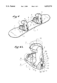
- FIG. 1 is a perspective view of a gliding board with two retaining devices according to one embodiment
- FIG. 1a is an enlargement of a retaining device of FIG. 1;
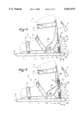
- FIG. 2 is a lateral view of a retaining device of FIG. 1;
- FIG. 3 is similar to FIG. 2 but corresponds to an alternative embodiment
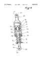
- FIG. 4 is a cross-section along the line IV--IV of FIG. 2 or 3;
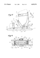
- FIG. 5 is a lateral view of a retaining device according to another embodiment.
- FIG. 6 is a cross-section along the line VI--VI of FIG. 5.
- FIGS. 1 and 1a show a gliding board 1 on top of which two devices 2 for retaining the boots 3 of a user are attached.
- Each device 2 includes a base 4 for holding the foot and a dorsal support element 5 for taking support especially in turns where the user presses on the rear running edge and has his back facing the slope.
- the devices 2 are respectively oriented in a substantially transverse direction of the board 1, such that the tips of the feet are close to a frontal longitudinal side 6, and that the heels are close to a rearward longitudinal side 7 of the board 1.
- Each device 2 includes means for retaining the boot 3 on the device 2, which means are represented by straps 8, 9, maintaining the boot 3 on the base 4 at the level of the foot, and includes a means for returning the dorsal support element on the lower part of the leg, which means is represented by a strap 10 maintaining the boot 3 on the dorsal support element 5 at the level of the lower part of the leg.
- the dorsal support element 5 is journalled with respect to the base 4 by a journal connection, which is represented here in the form of rivets 11, such that the dorsal support element 5 can pivot with respect to the base 4 about a substantially transverse Y-Y' axis of the device 2.
- the Y-Y' axis is transverse with respect to a longitudinal direction of the device 2 extending substantially from the toes toward the heel of the foot.
- the base 4 is shaped like a cradle, having a surface that receives the lower surface of the sole of the boot and a pair of laterally opposed upwardly extending portions.
- the rivets 11, or other journal connections connect the dorsal support element 5 and the upwardly extending portions of the base 4.
- an elastic means constantly biases the dorsal support element 5 with respect to the base 4 along a rotational movement with respect to the Y-Y' axis in a bending direction of the lower par of the leg toward the foot.
- This elastic means can be a compression spring 12 that is visible in FIGS. 1, 1a, 2, 3, 4.
- the spring 12 is guided by a rod 13 having a cylindrical section.
- the spring 12 takes support on one of its ends on a retainer 14 affixed to the rod 13 by any suitable means, such as a weld 15.
- the spring 12 takes support through the other end on a plug 16 which is itself fixed on a cylinder or sheath 17, for example, by means of a thread 18.
- the plug 16 is bored in its center by a hole 19 which serves to guide the rod 13 in a direction of compression or extension of the spring 12.
- the sheath 17 is extended at its end that is opposite the plug 16 by a flat portion 20 bored by a hole 21 having an axis 22.
- the rod 13 is extended at its end that comes out of the hole 19 by a flat portion 23 bored by a hole 24 having an axis 25.
- the rod 13 is therefore capable of penetrating into the sheath 17 against the action of the spring 12 by being guided in the sheath 17 through the hole 19 of the plug 16.
- the sheath 17 is journalled by the axis 22 common to a pin 26, to the hole 21 of the flat portion 20, and to two openings of a base 27, on the dorsal support element 5.
- the rod 13 is journalled by the axis 25 common to a pin 28, to the hole 24 of the flat portion 23, and to two openings of a base 29, on the base 4.
- the dorsal support element 5 and the base 4 are constantly biased in the direction of bending of the boot 3.
- a braking means or brake, constantly absorbs a penetrating movement of the rod 13 into the sheath 17.
- This braking means is represented here in the form of a seal 30 having a circular lip, the lip being oriented in a direction that opposes the entry of the rod 13, but does not prevent the exit thereof.
- the seal 30 is retained on the rod 13 by any suitable means, such as two rings 31, 32, which are themselves immobilized on the rod 13 by two pins 33, 34.
- a mechanism for stopping the displacement of the dorsal support element 5 with respect to the base 4 in a direction of extension of the foot is made, for example, by association of the end 35 of the sheath and of the top 36 of the rod 13. When the end 35 and the top 36 are in contact, the spring 12 is in a maximum compression state.
- the retaining device thus made enables a user to rapidly and easily bend the legs while biasing the rearward longitudinal side 7 of the board 1 toward the ground, due to the action of the constant action of the spring 12. A permanent contact is subsequently obtained between the rearward side 7 and the ground in the turns or on the bumps where the user has his back facing the slope of the terrain. The movements of the body and of the legs made to maintain the balance do therefore not disturb the operation of the board 1.
- the plug 16 could be made of bronze, the rod 13 of steel, the spring 12 of steel alloy.
- the lip seal 30 is preferably made of rubber or molded polyurethane.
- FIGS. 2 and 3 Two variations of the embodiment described appear in a lateral view in FIGS. 2 and 3.
- the dorsal support element 5 includes a shell 37 and an arch 38 forming a single block, made for example of injected plastic material.
- the dorsal support element 5 includes a shell 39 journalled on an arch 40 along a substantially longitudinal X-X' axis of the boot.
- the journal can be embodied as to a rivet or any other means and facilitates lateral inclinations of the lower part of the leg along the X-X' axis.
- the spirit of the invention remains unchanged. Indeed, the spring 12 constantly biases the lower part of the leg in flexion with respect to the foot in the direction of arrow F, by acting constantly between the arch 38 or 40 and the base 4 in a respective spacing direction.
- FIGS. 5 and 6 Another embodiment of the invention is proposed by means of FIGS. 5 and 6.
- the same elements are designated by the same reference numerals.
- a dorsal support element 5 including a shell 37 and an arch 38 are journalled on a base 4 along a substantially transverse Y-Y' axis.
- a torque spring 41 constantly acts between the base 4 and the arch 38 to bias the arch 38 and maintain the contact between the boot 3 and the shell 37. Indeed, ends 42 and 43 of the spring 41 are affixed to the base 4 and to the arch 38, respectively, by passing through holes of the base 4 and of the arch 38. The spring 41 remains in place due to the constant bias of an elastic washer 44 that is inserted between the base 4 and a shoulder 45 of a rivet 46 having a Y-Y' axis.
- the rivet 46 serves to maintain the base 4 and the arch 38 with respect to one another, and it also serves as a rotational guide for a wheel 47, a wheel 48 and a disk 49, which are all pierced in their center for the passage of the rivet 46, and are all located between the base 4 and the arch 38.
- the wheel 47 includes a flat side 50 affixed to the base 4 by any means, such as adhesion, and a toothed side 51 opposite the flat side 50.
- the wheel 48 includes a toothed side 52 whose contour is complementary to the side 51 of the wheel 47, and a flat side 53 affixed to the disk 4 by any means, such as adhesion.
- the disk 49 includes a side 54 affixed to the wheel 48, and a side 55 capable of sliding on the arch 38.
- the toothed wheels 47 and 48 behave like a free ratchet wheel allowing a single direction of rotation with respect to the Y-Y' axis.
- the disk 49 behaves like a brake which dissipates the energy by friction.
- the teeth of the wheels 47 and 48 are capable of being displaced with respect to one another when the arch 38 is displaced so as to allow for a bending of the foot, because the elasticity of the washer 44 enables a slight relative displacement in a spacing direction of the constituent walls of the arch 38 and of the base 4, subsequently to the action of the teeth.
- the inclination of the teeth acts in a single direction.
- the rivet 46, the base 4 and the arch 38 can be made of metal or synthetic material shaped by any known means such as injection or machining.
- the user can optionally detach the straps 8, 9, 10, or the automatic ratchet retention means, depending on the conditions of practice and usage of the gliding board 1.
Landscapes
- Footwear And Its Accessory, Manufacturing Method And Apparatuses (AREA)
Applications Claiming Priority (2)
| Application Number | Priority Date | Filing Date | Title |
|---|---|---|---|
| FR9605671 | 1996-05-02 | ||
| FR9605671A FR2748214B1 (fr) | 1996-05-02 | 1996-05-02 | Dispositif de retenue d'une chaussure sur une planche de glisse destinee a la pratique du surf |
Publications (1)
| Publication Number | Publication Date |
|---|---|
| US6032974A true US6032974A (en) | 2000-03-07 |
Family
ID=9491890
Family Applications (1)
| Application Number | Title | Priority Date | Filing Date |
|---|---|---|---|
| US08/848,649 Expired - Fee Related US6032974A (en) | 1996-05-02 | 1997-04-29 | Device for retaining a boot on a gliding board adapted for snowboarding |
Country Status (4)
| Country | Link |
|---|---|
| US (1) | US6032974A (de) |
| EP (1) | EP0804949A1 (de) |
| JP (1) | JPH1071227A (de) |
| FR (1) | FR2748214B1 (de) |
Cited By (17)
| Publication number | Priority date | Publication date | Assignee | Title |
|---|---|---|---|---|
| US6283492B1 (en) * | 1996-12-27 | 2001-09-04 | Noah W. Hale | Snowboard binding system and a snowboard step-in boot system with gradually increasing resistance |
| AT409937B (de) * | 2001-02-02 | 2002-12-27 | Innovationdesigncompany Produk | Snowboardbindung |
| US6533295B2 (en) * | 1999-12-13 | 2003-03-18 | Salomon S.A. | Device for retaining a boot on a gliding board |
| US6554296B1 (en) | 2000-04-28 | 2003-04-29 | The Burton Corporation | Highback with independent forward lean adjustment |
| US6672610B2 (en) * | 2001-01-31 | 2004-01-06 | HTM Sport- und Freizeitgeräte Aktiengesellschaft | Snowboard binding |
| US20040169343A1 (en) * | 2001-07-17 | 2004-09-02 | Fougere Raymond D. | Snowboard binding with tensioning member for determining neutral position |
| US20060022432A1 (en) * | 2004-08-02 | 2006-02-02 | The Burton Corporation | Convertible toe strap |
| US20060237920A1 (en) * | 2005-04-25 | 2006-10-26 | K-2 Corporation | Virtual forward lean snowboard binding |
| US20070075524A1 (en) * | 2003-09-08 | 2007-04-05 | Kelly David A | Snowboard brake |
| US20070132206A1 (en) * | 2003-07-31 | 2007-06-14 | Head Sport Ag | Snowboard binding |
| US20080129014A1 (en) * | 2006-12-01 | 2008-06-05 | The Burton Corporation | Highback with textile-like material for support |
| WO2009036710A3 (en) * | 2007-09-18 | 2009-05-07 | Milan Krampla | Ski-fastening with calf holder |
| US20090146397A1 (en) * | 2007-12-07 | 2009-06-11 | K-2 Corporation | Blockless highback binding |
| US20120235384A1 (en) * | 2003-02-11 | 2012-09-20 | Mark Elkington | Snowboard binding |
| US20130277924A1 (en) * | 2012-04-24 | 2013-10-24 | Koncept Technologies Inc. | Braking mechanism for roller skates |
| US9498699B2 (en) * | 2014-06-27 | 2016-11-22 | Salomon S.A.S. | Device for receiving a boot on a gliding apparatus |
| US20250072552A1 (en) * | 2022-01-06 | 2025-03-06 | K2I | Ski boot with rear lever part |
Families Citing this family (3)
| Publication number | Priority date | Publication date | Assignee | Title |
|---|---|---|---|---|
| US6631919B1 (en) | 2000-01-06 | 2003-10-14 | The Burton Corporation | Wing-shaped leg support for a highback |
| RU2229916C2 (ru) * | 2001-01-30 | 2004-06-10 | Рязанов Александр Геннадьевич | Устройство для крепления обуви к спортивному снаряжению |
| RU2297264C2 (ru) * | 2005-02-16 | 2007-04-20 | Александр Геннадьевич Рязанов | Устройство для крепления обуви к спортивному снаряду |
Citations (17)
| Publication number | Priority date | Publication date | Assignee | Title |
|---|---|---|---|---|
| US249964A (en) * | 1881-11-22 | Island | ||
| US983721A (en) * | 1909-12-23 | 1911-02-07 | Charles H Irish | Ankle-brace. |
| US2424198A (en) * | 1944-09-21 | 1947-07-15 | Vernon A Tauscher | Cable tension regulator |
| FR54219E (fr) * | 1945-10-13 | 1948-06-25 | Patin faisant usage de cycle | |
| FR60630E (fr) * | 1949-05-03 | 1954-11-22 | Fixation de ski | |
| FR2063622A5 (de) * | 1969-10-24 | 1971-07-09 | Starpool | |
| US3870325A (en) * | 1973-01-29 | 1975-03-11 | Edgar H Davis | Combined ski boot and binding |
| US3945134A (en) * | 1974-09-13 | 1976-03-23 | Alpine Research, Inc. | Ski boot |
| WO1983002397A1 (en) * | 1982-01-19 | 1983-07-21 | Burt, Lionel, J. | Apparatus for improved control of skis |
| US4476640A (en) * | 1980-12-02 | 1984-10-16 | Nordica S.P.A. | Device for controlling the flex of ski and the like boots |
| DE3622746A1 (de) * | 1986-07-07 | 1988-01-21 | Markus Laemmert | Bindung fuer monoski |
| DE8902125U1 (de) * | 1989-02-22 | 1989-05-11 | Carpenter, Jake Burton, Manchester Center, Vt. | Snowboardbindung |
| EP0351881A2 (de) * | 1988-07-22 | 1990-01-24 | Geze Sport International Gmbh | Bindungsgekoppelte Skistiefelschaftentriegelung |
| FR2650752A1 (fr) * | 1989-08-11 | 1991-02-15 | Boineau Christian | Dispositif pour pratiquer un sport de glisse sur la neige |
| US5106065A (en) * | 1989-09-11 | 1992-04-21 | Fichtel & Sachs Industries, Inc. | Self-blocking gas spring with temperature-responsive bypass valve |
| US5702091A (en) * | 1995-07-13 | 1997-12-30 | Draftex Industries Limited | Gas spring |
| US5865445A (en) * | 1996-07-12 | 1999-02-02 | K-2 Corporation | In-line skate brake |
-
1996
- 1996-05-02 FR FR9605671A patent/FR2748214B1/fr not_active Expired - Fee Related
-
1997
- 1997-04-12 EP EP97106029A patent/EP0804949A1/de not_active Withdrawn
- 1997-04-28 JP JP9110655A patent/JPH1071227A/ja active Pending
- 1997-04-29 US US08/848,649 patent/US6032974A/en not_active Expired - Fee Related
Patent Citations (18)
| Publication number | Priority date | Publication date | Assignee | Title |
|---|---|---|---|---|
| US249964A (en) * | 1881-11-22 | Island | ||
| US983721A (en) * | 1909-12-23 | 1911-02-07 | Charles H Irish | Ankle-brace. |
| US2424198A (en) * | 1944-09-21 | 1947-07-15 | Vernon A Tauscher | Cable tension regulator |
| FR54219E (fr) * | 1945-10-13 | 1948-06-25 | Patin faisant usage de cycle | |
| FR60630E (fr) * | 1949-05-03 | 1954-11-22 | Fixation de ski | |
| FR2063622A5 (de) * | 1969-10-24 | 1971-07-09 | Starpool | |
| US3870325A (en) * | 1973-01-29 | 1975-03-11 | Edgar H Davis | Combined ski boot and binding |
| US3945134A (en) * | 1974-09-13 | 1976-03-23 | Alpine Research, Inc. | Ski boot |
| US4476640A (en) * | 1980-12-02 | 1984-10-16 | Nordica S.P.A. | Device for controlling the flex of ski and the like boots |
| WO1983002397A1 (en) * | 1982-01-19 | 1983-07-21 | Burt, Lionel, J. | Apparatus for improved control of skis |
| DE3622746A1 (de) * | 1986-07-07 | 1988-01-21 | Markus Laemmert | Bindung fuer monoski |
| EP0351881A2 (de) * | 1988-07-22 | 1990-01-24 | Geze Sport International Gmbh | Bindungsgekoppelte Skistiefelschaftentriegelung |
| US5020823A (en) * | 1988-07-22 | 1991-06-04 | Geze Sport International Gmbh | Binding coupled ski boot shaft delatching device |
| DE8902125U1 (de) * | 1989-02-22 | 1989-05-11 | Carpenter, Jake Burton, Manchester Center, Vt. | Snowboardbindung |
| FR2650752A1 (fr) * | 1989-08-11 | 1991-02-15 | Boineau Christian | Dispositif pour pratiquer un sport de glisse sur la neige |
| US5106065A (en) * | 1989-09-11 | 1992-04-21 | Fichtel & Sachs Industries, Inc. | Self-blocking gas spring with temperature-responsive bypass valve |
| US5702091A (en) * | 1995-07-13 | 1997-12-30 | Draftex Industries Limited | Gas spring |
| US5865445A (en) * | 1996-07-12 | 1999-02-02 | K-2 Corporation | In-line skate brake |
Cited By (35)
| Publication number | Priority date | Publication date | Assignee | Title |
|---|---|---|---|---|
| US6283492B1 (en) * | 1996-12-27 | 2001-09-04 | Noah W. Hale | Snowboard binding system and a snowboard step-in boot system with gradually increasing resistance |
| US6533295B2 (en) * | 1999-12-13 | 2003-03-18 | Salomon S.A. | Device for retaining a boot on a gliding board |
| US7077403B2 (en) | 2000-04-28 | 2006-07-18 | The Burton Corporation | Highback with independent forward lean adjustment |
| US6554296B1 (en) | 2000-04-28 | 2003-04-29 | The Burton Corporation | Highback with independent forward lean adjustment |
| US6736413B2 (en) | 2000-04-28 | 2004-05-18 | The Burton Corporation | Highback with independent forward lean adjustment |
| US7748729B2 (en) | 2000-04-28 | 2010-07-06 | The Burton Corporation | Highback with independent forward lean adjustment |
| US20060249930A1 (en) * | 2000-04-28 | 2006-11-09 | The Burton Corporation | Highback with independent forward lean adjustment |
| US6672610B2 (en) * | 2001-01-31 | 2004-01-06 | HTM Sport- und Freizeitgeräte Aktiengesellschaft | Snowboard binding |
| AT409937B (de) * | 2001-02-02 | 2002-12-27 | Innovationdesigncompany Produk | Snowboardbindung |
| US20040169343A1 (en) * | 2001-07-17 | 2004-09-02 | Fougere Raymond D. | Snowboard binding with tensioning member for determining neutral position |
| US7029023B2 (en) * | 2001-07-17 | 2006-04-18 | Fougere Raymond D | Snowboard binding with tensioning member for determining neutral position |
| US20140291968A1 (en) * | 2003-02-11 | 2014-10-02 | Flow Sports, Inc. | Snowboard binding |
| US20120235384A1 (en) * | 2003-02-11 | 2012-09-20 | Mark Elkington | Snowboard binding |
| US8544870B2 (en) * | 2003-02-11 | 2013-10-01 | Flow Sports, Inc. | Snowboard binding |
| US8752845B2 (en) * | 2003-02-11 | 2014-06-17 | Flow Sports, Inc. | Snowboard binding |
| US20070132206A1 (en) * | 2003-07-31 | 2007-06-14 | Head Sport Ag | Snowboard binding |
| US20070075524A1 (en) * | 2003-09-08 | 2007-04-05 | Kelly David A | Snowboard brake |
| US20060022432A1 (en) * | 2004-08-02 | 2006-02-02 | The Burton Corporation | Convertible toe strap |
| US7614638B2 (en) | 2004-08-02 | 2009-11-10 | The Burton Corporation | Convertible toe strap |
| US7618054B2 (en) | 2004-08-02 | 2009-11-17 | The Burton Corporation | Convertible toe strap |
| US8215660B2 (en) | 2004-08-02 | 2012-07-10 | The Burton Corporation | Convertible toe strap |
| US20110175327A1 (en) * | 2004-08-02 | 2011-07-21 | The Burton Corporation | Convertible toe strap |
| US20060022433A1 (en) * | 2004-08-02 | 2006-02-02 | The Burton Corporation | Convertible toe strap |
| US20060237920A1 (en) * | 2005-04-25 | 2006-10-26 | K-2 Corporation | Virtual forward lean snowboard binding |
| US20080129014A1 (en) * | 2006-12-01 | 2008-06-05 | The Burton Corporation | Highback with textile-like material for support |
| US7686321B2 (en) | 2006-12-01 | 2010-03-30 | The Burton Corporation | Highback with textile-like material for support |
| WO2009036710A3 (en) * | 2007-09-18 | 2009-05-07 | Milan Krampla | Ski-fastening with calf holder |
| CN101801475B (zh) * | 2007-09-18 | 2012-06-27 | M·克兰普拉 | 滑雪板紧固装置 |
| US20100207361A1 (en) * | 2007-09-18 | 2010-08-19 | Milan Krampla | Ski-fastening with calf holder |
| US7992888B2 (en) | 2007-12-07 | 2011-08-09 | K-2 Corporation | Blockless highback binding |
| US20090146397A1 (en) * | 2007-12-07 | 2009-06-11 | K-2 Corporation | Blockless highback binding |
| US20130277924A1 (en) * | 2012-04-24 | 2013-10-24 | Koncept Technologies Inc. | Braking mechanism for roller skates |
| US8777235B2 (en) * | 2012-04-24 | 2014-07-15 | Koncept Technologies Inc. | Braking mechanism for roller skates |
| US9498699B2 (en) * | 2014-06-27 | 2016-11-22 | Salomon S.A.S. | Device for receiving a boot on a gliding apparatus |
| US20250072552A1 (en) * | 2022-01-06 | 2025-03-06 | K2I | Ski boot with rear lever part |
Also Published As
| Publication number | Publication date |
|---|---|
| FR2748214B1 (fr) | 1998-07-31 |
| FR2748214A1 (fr) | 1997-11-07 |
| JPH1071227A (ja) | 1998-03-17 |
| EP0804949A1 (de) | 1997-11-05 |
Similar Documents
| Publication | Publication Date | Title |
|---|---|---|
| US5701689A (en) | Snowboard boot | |
| US5446976A (en) | Boot for performing a gliding sport with an elastic device for biasing the collar | |
| AU689910B2 (en) | Braking mechanism for in-line skates | |
| US5727808A (en) | Free heel/anterior release ski binding | |
| US4447968A (en) | Multidirectional dynamic fitting system for sport shoe | |
| US20090320330A1 (en) | Footwear with improved bottom assembly | |
| JPH1071227A (ja) | サーフィンを行うための滑走用ボード上に靴を保持する装置 | |
| US3718995A (en) | Hinge boot | |
| JP3740126B2 (ja) | スポーツ靴用ストラップアセンブリ | |
| US7503579B2 (en) | Device for retaining a foot or boot on a sports apparatus | |
| EP0884004B1 (de) | Schuhwerk | |
| US5412883A (en) | Ski boot and ski boot-bindings | |
| DE3561374D1 (en) | Sports shoe, in particular a ski boot | |
| US20160366985A1 (en) | Footwear element to be mounted on an apparatus, and equipment including such footwear element and apparatus | |
| US5657999A (en) | In-line roller blade braking device | |
| US5957478A (en) | Release binding for telemark skiing, back country skiing, and ski jumping | |
| US6142503A (en) | Device for holding a boot on a snowboard | |
| JPH10508209A (ja) | ローラースケート靴のブレーキ装置 | |
| US4265462A (en) | Support device for skiers | |
| US6533295B2 (en) | Device for retaining a boot on a gliding board | |
| US6082768A (en) | Roller ski | |
| WO2016063073A1 (en) | Cycle shoe cleat apparatus and shoe | |
| US6616171B2 (en) | Device for raising at least one binding element used on a board for gliding | |
| US5558353A (en) | Device for modifying the force distribution of a ski over its gliding surface and a ski equipped with such a device | |
| FR2497109B1 (fr) | Fixation de ski a declenchement |
Legal Events
| Date | Code | Title | Description |
|---|---|---|---|
| AS | Assignment |
Owner name: SALOMON S.A., FRANCE Free format text: ASSIGNMENT OF ASSIGNORS INTEREST;ASSIGNOR:SAILLET, BENOIT;REEL/FRAME:008676/0917 Effective date: 19970728 |
|
| FPAY | Fee payment |
Year of fee payment: 4 |
|
| REMI | Maintenance fee reminder mailed | ||
| LAPS | Lapse for failure to pay maintenance fees | ||
| STCH | Information on status: patent discontinuation |
Free format text: PATENT EXPIRED DUE TO NONPAYMENT OF MAINTENANCE FEES UNDER 37 CFR 1.362 |
|
| FP | Expired due to failure to pay maintenance fee |
Effective date: 20080307 |