US6079593A - Storage container for stackable consumer articles - Google Patents
Storage container for stackable consumer articles Download PDFInfo
- Publication number
- US6079593A US6079593A US09/142,117 US14211798A US6079593A US 6079593 A US6079593 A US 6079593A US 14211798 A US14211798 A US 14211798A US 6079593 A US6079593 A US 6079593A
- Authority
- US
- United States
- Prior art keywords
- slide
- storage container
- unloading device
- holding
- stop
- Prior art date
- Legal status (The legal status is an assumption and is not a legal conclusion. Google has not performed a legal analysis and makes no representation as to the accuracy of the status listed.)
- Expired - Fee Related
Links
Images




Classifications
-
- B—PERFORMING OPERATIONS; TRANSPORTING
- B01—PHYSICAL OR CHEMICAL PROCESSES OR APPARATUS IN GENERAL
- B01L—CHEMICAL OR PHYSICAL LABORATORY APPARATUS FOR GENERAL USE
- B01L9/00—Supporting devices; Holding devices
- B01L9/54—Supports specially adapted for pipettes and burettes
- B01L9/543—Supports specially adapted for pipettes and burettes for disposable pipette tips, e.g. racks or cassettes
Definitions
- the invention relates to a storage container, an unloading device and a slide for removing palettes, as described in the preambles of claims 1, 2, 14 and 29.
- Such unloading devices and storage containers are used to remove consumer articles stacked therein, e.g. articles on palettes, for example pipette tips inserted into holed palettes and the like, separately palette by palette from the storage container.
- the objective of the invention is to create a storage container, a slide and an unloading device for removal in order to obtain transportation in which the goods are protected and kept away from environmental influences, and easy handling for the separate unloading of the goods directly from the storage container.
- the storage container can hold a stack of consumer articles predetermined by the height of the storage container, whereby by inserting the stack into the storage container from the base or lid side or placing the storage container over a stack an automated and thereby also sterile packaging is possible. Then to remove individual consumer articles only the assigned slide needs to be pushed onto the storage container, which by sliding backwards and forwards relative to the storage container after opening or removing the base opening permits the separate unloading of consumer articles from the bottom of the stack. Owing to its simple design the storage container can be manufactured efficiently and from different materials, preferably the housing can also be made of cardboard or plastic.
- the preferred development according to claim 3 permits at any time the use of an separating device on the storage container, so that no additional equipment is required for the individual removal of palettes from the storage container.
- a simple design of the separating device and the separating sequence can be achieved by the embodiment according to claim 5.
- the preferred embodiment according to claim 7 permits a controlled movement of the separating device without the slide becoming detached from the guiding region of the storage container.
- the storage container can be used at the same time as a magazine for removing the palettes.
- the embodiment according to claim 9 simplifies not only the loading of the storage container, but also permits the refilling thereof or the repacking of palettes if too many have been removed from the storage container by mistake.
- An embodiment according to claim 10 is also advantageous as thereby without additional measures palettes can also be inserted into the storage container, which are projected over by the parts inserted therein in the direction of the base opening.
- a development according to claim 12 is also advantageous, as in this way the use of only one slide for separating the palettes is required.
- the design according to claim 13 is also advantageous, as in this way the storage container can also be used simultaneously for the transport of the palette and for the subsequent unloading thereof.
- the objective of the invention can also be achieved independently by means of the slide according to claim 14. It is advantageous in this case that by only pushing the slide backwards and forwards on the outside of the storage container by means of limit stops arranged thereon the consumer articles can be held in the storage container, and on deforming the limit stops or the holding arms by the resulting release of the palettes or consumer articles the latter can be removed individually from the storage container for example, whereby by means of the elastic restoring action of the holding arms further consumer articles or palettes can be reliably prevented from falling out.
- a simple manufacture from elastically resilient materials and a longer lifetime is achieved by the characteristics according to claim 15.
- a design according to claim 16 is also advantageous as thereby consumer articles which slide down before the latter can pass through the base opening are held back until the consumer article or palette previously released has passed through the base opening of a storage container.
- a design according to claim 17 is advantageous, in which it is ensured that with every sliding action of the slide only one consumer article or one palette can be removed individually.
- a longer lifetime and a greater retaining force can be obtained by the development according to claim 18.
- a development according to claim 19 is also possible, by means of which a simplified design of the slide can be obtained.
- a user-friendly solution for the slide is characterised in claim 20.
- the guiding sleeve is designed according to claim 21.
- a safe separation and exact guiding of the packaging units can be achieved by the development according to claim 24.
- the design according to claim 25 is also advantageous, as by means of a precise guiding of the holding arms a lengthened period of use is ensured.
- a high load-bearing slide is obtained by the design according to claim 26.
- the objective of the present invention is also achieved independently by the unloading device according to claim 29.
- the limit stops projecting over the openings into the storage container by sliding the slide into a position, in which it is pressed out of the openings, a consumer article can be released, and in another position the consumer articles can be held back in the storage container.
- a division of the holding and release forces on the palettes or consumer articles is achieved by the embodiment according to claim 31.
- the lifetime of the slide can finally be extended by means of the embodiment according to claim 52.
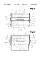
- FIG. 1 a storage container according to the invention in partly cross-sectional front view
- FIG. 2 a slide for the storage container according to FIG. 1 also in a partly cross-sectional front view;
- FIG. 3 a slide for the storage container according to FIG. 1 from underneath;
- FIG. 4 position of the unloading device before the release of the first consumer article
- FIG. 5 position of the unloading device after the release of the first consumer article
- FIG. 6 position of the unloading device before the removal of the second consumer article
- FIG. 7 an unloading device according to the invention with a storage container for a stack of palettes in partial cross section;
- FIG. 8 a partial region of the storage container with an output device in holding position, in cross section
- FIG. 9 a partial region according to FIG. 8 in a release position of the holding device
- FIG. 10 a different embodiment of the unloading device according to the invention with the storage container in view;
- FIG. 11 the unloading device with the storage container, in cross section, along the lines XI--XI of FIG. 10;
- FIG. 12 the unloading device according to FIG. 11 in release position for the separate removal of a palette
- FIG. 13 an additional design of an unloading device with a storage container in view, partly in cross section;
- FIG. 14 the unloading device with the storage container in plan view
- FIG. 15 an additional design of the storage container of the invention with a U-shaped slide in view
- FIG. 16 a detailed view of a different embodiment of the separating device with an storage container, in cross section.
- a cuboid storage container 7 fitted to the shape of the consumer articles 1 and designed as a stack housing is provided with a removable base seal 8, designed as a base insert, which has upright side parts 9 designed as support walls to support the stack of consumer articles 1 inside the storage container 7.
- the storage container 7 forms a magazine for the consumer articles, is closed by a lid 10 and provided with a viewing opening 11 in the form of a viewing window for checking the content.
- FIGS. 2 and 3--a slide 19 which can be slid onto the storage container 7 is provided, which is e.g. in the form of a covering sleeve, and which on all four sleeve sides 20, 21 in the bottom edge region forms downwards pointing, flexible holding arms 22, 23 designed as holding tongues, with inwardly angled hook-shaped limit stops 24, 25.
- Said limit stops 24, 25, have projecting holding parts 29, 30 widened relative to the engagement openings, so that with the sleeve or slide 19 pushed onto the storage container 7 depending on the relative height to the openings 15, 16 the limit stops 24, 25 engage with their holding parts 27, 28 into the openings 15, 16 and are supported with the bearing parts 29, 30 on the side walls 12, 13 of the storage container 7, the other one above or below the openings 15, 16 the holding parts 27, 28 are pushed out of the latter and are supported on the side walls 12, 13.
- the width 26 of the holding parts 27, 28 can here correspond to a width 31 of the openings 15, 16 or be smaller than the that of the openings 15, 16.
- the limit stops 24, 25 lie in pairs opposite the side walls 12, 13, whereby the respectively opposite limit stops 24 or 25 are arranged at the same level as the two holding parts 27 or 28.
- the limit stops 24 or their holding arms 27 are however relative to the limit stops 25 or the holding arms 28 offset in height by a vertical offset 32 which is smaller than the height 33 of the openings 15, 16 and also smaller than the distance 34 between the holding edges 6 of two consumer articles 1 stacked on top of one another.
- bottom slide stop 35 comprises outwardly projecting sleeve tabs 37 of the slide 19 and the top slide stop 36 comprises side tabs 38 of the storage container 7.
- the storage container 7 If the storage container 7 is used as packaging, it holds, as indicted in FIG. 1, a stack of consumer articles 1 and is sealed by the base seal 8, whereby the base seal 8 with its side parts 9 supports and secures the stack of consumer articles inside the storage container 7 and also covers the openings 15, 16.
- the shaft base is completely open and the storage container 7 can be placed onto a suitable base 39 for the transfer of the individual consumer articles 1 which takes over the individual consumer articles 1 removed through the open housing base.
- the slide 19 is pushed downwards relative to the storage container 7 to the bottom limit stops 25 or their holding parts 28 and also the top limit stops 24 or their holding parts 27 engage in the openings 15, 16, so that in this way the bottom last consumer article 1 is held by the lowest limit stops 25 or their holding parts 28, and the last consumer article 1 but one is held by the top limit stops 24 or their holding parts 27 by gripping under their holding edges 6 (FIG. 4).
- the bottom limit stops 25 hit a bottom edge 40 of the openings 16 designed as the bottom opening edge and are pressed outwards on further pushing, so that they slide externally onto the side walls 13 and release the holding edge 6 of the last consumer article 1.
- the latter falls by force of gravity onto the base 39, as shown by dashed lines, where there is a suitable base and support (FIG. 5).
- the bottom sliding stop 35 prevents by hitting the base 39 a further downwards sliding of the slide 19 relative to the storage container 7, whereby also a pressing out of the top limit stops 24 from the openings 15 extending between a top and bottom edge 41, 42 is prevented.
- Pushing up the slide 19 then lifts up the consumer articles 1 remaining in the storage container 7, which are suspended on the top limit stops 24 or their holding parts 27 until the top limit stops 24 reach the top edge 41 of the opening 15, and on pushing further are pressed outwards, whereby the top limit stops 24 release the stack of consumer articles, which in this way slides by force of gravity to the bottom limit stops 25 which on sliding up the slide 19 are again snapped into the openings 16 which are delimited to the top by a top edge 43, and undergrip the holding edge 6 of the lowest consumer article 1 (FIG. 6).
- top sliding stop 36 prevents further upwards sliding of the slide 19 relative to the storage container 7, and thereby also a pressing out of the bottom limit stops 25 from the assigned openings 16.
- the base 39 with the individually unloaded consumer article 1 can be taken off from the storage container 7 and the consumer article 1 can be removed.
- the base or a different base 39 is placed at the base of the storage container 7, so that with a repeat downwards sliding of the slide 19 the limit stops 24 in turn engage in the opening 15 and hold the last consumer article 1 but one on its holding edge 6 (FIG. 4) so that the unloading process can be performed again.
- the storage container 7 according to the invention is characterised by its simplicity, efficient manufacturability, operating safety and good handling properties.
- a storage container 102 e.g. a box, is shown designed as packaging 101. It is cuboid and is formed by four side walls 103 arranged at right angles relative to one another and is sealed at one face end by a lid 104 formed e.g. by overlapping lid tabs. The other face end forming a base opening 105 is sealed by a bowl-shaped base part 106 which overlaps the side walls 103 in an inner chamber 107 of the storage container 102 with side parts 108 and is connected with the latter detachably e.g. by adhesive applied in points.
- the storage container 102 is for holding palettes 111 fitted with components 1 10, e.g. holed palettes for storing pipette tips 112, whereby the palettes 111 are stacked in parallel to one another in the direction of a height 113 of the storage container 102, in that the pipette tips 112 of the individual layers are placed inside one another owing to their conical shape.
- components 1 10 e.g. holed palettes for storing pipette tips 112
- rectangular openings 116 are arranged approximately parallel to the face edges 115, which extend over a part of the width 117 of the side wall 103.
- a top edge 118 of the opening 116 opposite the face edge 115 has a distance 119 from the face edge 115, which corresponds approximately to a length 120, by which the pipette tips 112 project over an underside 121 of the palettes 111.
- the distance 114 by which a bottom edge 122 is spaced apart from the face edges 115 is smaller than the height 123 between the stacked palettes 111.
- the side parts 108 of the base part 106 overlap the side walls 103 up to the level of the top edge 118, whereby front faces 124 of the side parts 108 facing the inner chamber 107 form bearing surfaces 125 for the underside 121 of the lowest palette 111 of the stack of palettes when the storage container 102 is closed.
- a slot-shaped viewing opening 126 is also arranged in the direction of the height 113, in order to be able to control the filling level of the storage container 102.
- the face walls 103 of the face edge 115 have recesses 127 extending in the direction of the height 113, which make it possible to remove the base part 106 from the inner chamber 107 of the storage container 102.
- the storage container 102 is also provided with a separating device 128 which is guided in a guiding device 129 arranged on preferably two opposite side walls 103 for a slide 130 with a guiding extension 131 adjustable therein in perpendicular direction to the base opening 105.
- the guiding extension 131 has a holding arm 132 projecting in the direction of the face edges 115, which comprises a hook-like limit stop 133 projecting in the direction of the side wall 103.
- the holding arm 132 is spring-loaded in the direction of the side wall 103, whereby the limit stop 133 penetrates the side wall 103 in the opening 116 and with the storage container 102 sealed by the base part 106 is restricted by the latter in its movement in the direction of the inner chamber 107.
- the slide 130 can be in the form of a sleeve and surrounds the storage container 102 externally, and is preferably made of transparent material so that the visibility of the inner chamber 107 through the viewing opening 126 is not hindered.
- FIGS. 8 and 9 the individual unloading of the palette 111 with the pipette tips 112 from the storage container 102 is shown.
- the stack of palettes 111 is held back by the limit stops 133 projecting the opposite side walls 103 through the openings 116 into the inner chamber 107.
- the storage container 102 is placed with its base opening 105 onto a carrier housing 138, which comprises a cover plate 139 facing the palettes 111, which is provided with bores 140 arranged concentrically to the pipette tips 112.
- a carrier housing 138 which comprises a cover plate 139 facing the palettes 111, which is provided with bores 140 arranged concentrically to the pipette tips 112.
- the slide 130 and thereby the holding arms 132 is moved in the direction of the base opening 105--according to arrow 141.
- the bottom edge 122 of the opening 116 forms a sliding track for the holding arm 132 or the limit stop 133 securely connected therewith, which permits the movement of the holding arm 132 and thereby the limit stop 133 against the spring force of the holding arm 132 in the opposite direction to the inner chamber 107 into a release position, in which the limit stops 133 slide onto an outer face 142 of the side walls 103 and release the inner chamber 107, whereby the stack of palettes 111 falls until the bottom palette 111 lies on the cover plate 139 of the carrier housing 138.
- the distance 114 of the bottom edge 122 of the opening 116 is selected from the bearing surface 143 of the carrier housing 138 for the face edges 115, so that between the bottom edge 122 and the underside 121 of the overlying palette 111 there is a distance 144, which is greater than a thickness 145 of the limit stop 133. If there is now a movement of the slide 130 and thereby the holding arm 132 in the opposite direction to the base opening 105 the limit stop 133 slides after reaching the opening 116 into the inner chamber 107 and thereby adopts a holding back position for the other palettes 111 in the stack.
- the slide 130 is designed as a sleeve surrounding the side walls 103, producing perfect guiding on the outer surfaces 142 of the storage container 102.
- the slide 130 is also possible to provide openings 116 in all four side walls 103, and perform the separation of the palettes 111 from all four sides by means of holding arms 132 and limit stops 133 arranged on the sleeve, and thereby obtain a secure mounting and retaining of the stack of palettes 111.
- Such a design with holding arms 132 acting on all four sides is necessary for larger weights.
- FIGS. 10 to 12 a different embodiment of the storage container 102 and the separating device 128 is shown.
- the slide 130 surrounding the side walls 103 like a sleeve comprises in the direction of the base opening 105 the holding arm 132 with the limit stop 133 in the holding position passing through the opening 116 in the side wall 103 of the storage container 102 into the inner chamber 107, which limit stop comprises a holding part 27. In this way the stack of palettes 111 in the storage container 102 is securely held before unloading.
- a further tongue-like holding arm 147 extending further in the direction of the base opening 105 formed by a U-shaped cut-out 146 which comprises a retaining extension 148 designed as a holding part 28 projecting in the direction of the side wall 103.
- the retaining extension 148 is offset opposite the direction of the base opening 105 by a vertical offset 149, which is smaller than the vertical distance 123 between the two palettes 111 stacked on top of one another.
- the height 150 of the opening 116 is equal to the vertical offset 149.
- the limit stop 133 is moved by the bottom edge 122 of the opening 116 acting as a sliding track in the direction of the release position, in which the limit stop 133 releases the inner chamber 107, by means of the elastic displaceability of the holding arm 132.
- the retaining extension 148 preloaded with the slide 130 via the holding arm 147 in the direction of the inner chamber 107 reaches the top edge 118 of the opening 116 and with a continuation of the movement of the slide 130 penetrates into the inner chamber 107 between the palette 111 released by the limit stop 133 and thereby holds back the overlying stack of palettes 111.
- the released bottom palette 111 is hereby placed onto the carrier housing 138, on which the storage container 102 is placed to unload the palettes 111.
- the top edge 118 of the opening 116 acts as a sliding track for the retaining extension 148 and moves the latter with the holding arm 147 into a release position, in which the retaining extension 148 releases the inner chamber 107.
- the holding arm 132 with the limit stop 133 pivots after exceeding the bottom edge 122 of the opening 116 as a result of the elastic preloading into the inner chamber 107. Thereby the stack of palettes 111 in the inner chamber 107 is lowered to the level of the limit stop 133 and is prepared for the individual removal of a further palette 111.
- the previously unloaded palette 111 with the pipette tips 112 can be removed with the carrier housing 138 for further treatment, and a prepared additional carrier housing or the same carrier housing 138 can be positioned under the storage container 102 after the removal of the palette 111 with the pipette tips 112 for the removal of a further palette 111.
- the height 150 should be smaller than the vertical distance 123 between the stacked palettes 111.
- the vertical offset 149 including the thickness 145 of the retaining extension 148 or the limit stop 133 should be slightly smaller than the height 150 of the opening 116.
- the slide 130 independently of the holding arm 132 has a sleeve tab 37 projecting in the direction of the base opening 105, which is aligned with the face edge 151 facing the base opening 105 with an underside 152 of the limit stop 133.
- the displacement path 137 between the stop 136 and the carrier housing 138 is thereby restricted, as the face edge 151 in the separating process is set onto a facing edge 153 of the carrier housing 138 and in this way further sliding is prevented.
- the design of the holding arms 132, 147 with the limit stop 133 and the retaining extension 148 is possible on at least two opposite side walls 103 with a corresponding arrangement of openings 116 and also on all four side walls 103.
- FIGS. 13 and 14 a different embodiment of the storage container 102 with the separating device 128 is shown.
- the storage container 102 is surrounded by the slide 130 on all four side walls 103.
- the holding arms 132, 147 projecting in the direction of the base opening 105 are arranged with the limit stops 133 and retaining extensions 148 formed in the shape of a hook in the direction of the storage container 102.
- two holding arms 132 comprising the limit stops 133 are provided on opposite side walls 103 and the holding arms 147 with the retaining extensions 148 are provided on the additional opposite side walls 103.
- the separating device 128 formed by the slide 130 with the holding arms 132, 147 and limit stops 133 and retaining extensions 148 is pushed from below onto the storage container 102 up to the stop 136 delimiting the upper position.
- the limit stops 133 are arranged in the region of the openings 116, which are still covered by upright side parts of the base part, as shown in FIG. 7. If the base part is now removed downwards because of the spring preloading of the holding arms 132 the limit stops 133 which comprise holding parts 27 enter the inner chamber 107 on the underside 121 of the bottom palette 111 and hold back the stack of palettes 111 in the inner chamber 107.
- the limit stops 133 are pressed outwards on the bottom edge 122 of the opening 116 acting as a sliding track.
- the retaining extensions 148 reach the opening 116 and snap owing to the spring action of the holding arms 147 with holding parts 28 into the inner chamber 107 immediately underneath the underside 121 of the last palette 111 but one.
- the remaining stack of palettes 111 is held back in the inner chamber 107, whilst the bottom palette 111 is released and falls onto the prepared carrier housing 138 as a result of gravity.
- the stack of palettes 111 remaining in the inner chamber 107 is lifted up by the retaining extensions 148 projecting into the inner chamber 107.
- a stop arrangement 157 is provided in the form of a fixed stop 154, e.g. a bolt connected immovably to the storage container 102 and a longitudinal slot 156 arranged in the slide 130 in the direction of movement which is penetrated by the bolt 155.
- the bolt 155 forms also a guiding part 158 and can also be provided with a mushroom-shaped head 159 covering the longitudinal slot 156 which is connected detachably to the bolt 155.
- FIG. 15 the storage container 102 is shown fitted onto the carrier housing 138.
- guiding arrangements 160 for the slides 130 are arranged which permit displacement in the longitudinal direction of the storage container 102.
- the slides 130 are U-shaped in this embodiment and surround the storage container 102 from the upper side in the direction of the base opening 105, whereby projecting over the guiding arrangement 160, the slides 130 comprise the holding arms 132 with the limit stops 133 or holding arms 147 with retaining extensions 148 which are supported on the side walls 103 forming a preloading, and in the respective sliding position penetrate the openings 116 of the side walls 103.
- the slides 130 are provided with the holding arms 132 and the limit stops 133 and the holding arms 147 with the retaining extensions 148.
- the slide 130 with the limit stops 133 and the slide 130 with the retaining extensions 148 are operated independently in this embodiment.
- FIG. 16 a further embodiment is shown for the separate removal of palettes 111 from the storage container 102.
- one of the side walls 103 has a retaining strip 161 projecting into he inner chamber 107 in the direction of the opposite side wall 103, which is provided with a support surface 162 inclined in the direction of the base opening 105.
- the side wall 103 opposite the retaining strip 161 has the opening 116 for the limit stop 133.
- a positioning shoulder 164 forming a sliding track 163 and projecting from the side wall 103 into the inner chamber 107, which projects over an inner surface 165 by a distance 166, which is equal to a distance 167 by which the retaining strip 161 projects over the opposite side wall 103.
- An inside width 168 of the storage container 102 corresponds in this embodiment approximately to the length 169 of the palette 111 as well as the distance 166 or distance 167.
- the limit stops 133 are pressed out of the inner chamber 107.
- the palette 111 after passing the positioning shoulder 164 offset to the side from the retaining strip 161 is released by the limit stop 133 and owing to gravity passes the inclined support surface of the retaining strip and is thus unloaded onto the carrier housing 138.
- the distance 170 of the top edge 118 from the base opening 105 is slightly smaller than the vertical distance 123 between the stacked palettes 111.
- a counter stop 174 connected to the side wall 103 penetrating a slot-shaped recess 171 of the holding arm 132 and acting with a spacing element 172 on an outer surface 173 of the holding arm 132 is arranged. This effects in connection with the inclined position of the holding arm 132 with upwards movement an additional force component supporting the spring elasticity in the direction of the inner chamber 107 or a movement-dependent insertion of the limit stop 133 into the inner chamber 107.
Landscapes
- Health & Medical Sciences (AREA)
- Clinical Laboratory Science (AREA)
- Chemical & Material Sciences (AREA)
- Chemical Kinetics & Catalysis (AREA)
- Stackable Containers (AREA)
- Stacking Of Articles And Auxiliary Devices (AREA)
- Devices For Use In Laboratory Experiments (AREA)
- Telephonic Communication Services (AREA)
- Nonmetallic Welding Materials (AREA)
- Warehouses Or Storage Devices (AREA)
Applications Claiming Priority (5)
| Application Number | Priority Date | Filing Date | Title |
|---|---|---|---|
| AT42796A AT404788B (de) | 1996-03-07 | 1996-03-07 | Magazin für eine mehrzahl stapelbarer verbrauchseinheiten |
| AT427/96 | 1996-08-07 | ||
| AT142596A AT404789B (de) | 1996-08-07 | 1996-08-07 | Ausgabevorrichtung mit einem aufnahmebehälter für stapelbare verbrauchseinheiten |
| AT1425/96 | 1996-08-07 | ||
| PCT/AT1997/000039 WO1997032665A1 (de) | 1996-03-07 | 1997-02-28 | Aufnahmebehälter für stapelbare verbrauchseinheiten |
Publications (1)
| Publication Number | Publication Date |
|---|---|
| US6079593A true US6079593A (en) | 2000-06-27 |
Family
ID=25592712
Family Applications (1)
| Application Number | Title | Priority Date | Filing Date |
|---|---|---|---|
| US09/142,117 Expired - Fee Related US6079593A (en) | 1996-03-07 | 1997-02-28 | Storage container for stackable consumer articles |
Country Status (8)
| Country | Link |
|---|---|
| US (1) | US6079593A (de) |
| EP (1) | EP0885063B1 (de) |
| JP (1) | JP2000506064A (de) |
| AT (1) | ATE221415T1 (de) |
| AU (1) | AU1759297A (de) |
| CA (1) | CA2248217A1 (de) |
| DE (1) | DE59707862D1 (de) |
| WO (1) | WO1997032665A1 (de) |
Cited By (6)
| Publication number | Priority date | Publication date | Assignee | Title |
|---|---|---|---|---|
| US6405870B1 (en) * | 1999-08-09 | 2002-06-18 | Thermo Labsystems Oy | Tip kit |
| US20030215360A1 (en) * | 2002-05-15 | 2003-11-20 | Genetix Limited | Liquid handling robot for well plates |
| US20050274814A1 (en) * | 2004-06-09 | 2005-12-15 | William Schwartz | Selectable coolant heating option for electric vehicle |
| US20060108197A1 (en) * | 2003-01-06 | 2006-05-25 | Toshio Okuyama | Device for discharge rod-like product whose one end is larger sized |
| US8909094B2 (en) | 2001-02-19 | 2014-12-09 | Canon Kabushiki Kaisha | Sealing member, toner accommodating container and image forming apparatus |
| US11376598B2 (en) * | 2017-05-12 | 2022-07-05 | Universal Bio Research Co., Ltd. | Cartridge for nucleic acid detection |
Families Citing this family (6)
| Publication number | Priority date | Publication date | Assignee | Title |
|---|---|---|---|---|
| WO2001034303A1 (de) * | 1999-11-06 | 2001-05-17 | Loesch Martin | Vorratsbehälter mit ausgabevorrichtung für vereinzelte paletten |
| WO2009126945A2 (en) * | 2008-04-11 | 2009-10-15 | Pelican Group Holdings, Inc. | Pipette tip handling devices and methods |
| US8590736B2 (en) | 2009-04-11 | 2013-11-26 | Biotix, Inc. | Automated pipette tip loading devices and methods |
| USD690027S1 (en) | 2009-04-11 | 2013-09-17 | Biotix, Inc. | Pipette tip handling device |
| DE102010028715B4 (de) * | 2010-05-07 | 2024-05-29 | Syntegon Technology Gmbh | Vorrichtung und Verfahren zur Überprüfung von Objekten für pharmazeutische Anwendungen |
| GB2500242A (en) * | 2012-03-15 | 2013-09-18 | Ds Smith Plastics Ltd | Tray with movable apertured plate to locate contents or allow nesting |
Citations (8)
| Publication number | Priority date | Publication date | Assignee | Title |
|---|---|---|---|---|
| DE1918629A1 (de) * | 1968-04-17 | 1969-11-06 | Becuwe S A | Vorrichtung zum selbsttaetigen Ausgeben von Gegenstaenden |
| DE1554664A1 (de) * | 1966-09-29 | 1970-03-12 | Cease Central Inc | Warenausgabegeraet |
| DE1817547A1 (de) * | 1967-04-05 | 1970-07-23 | Cease Central Inc | Ausgabevorrichtung |
| FR2174322A5 (de) * | 1972-02-28 | 1973-10-12 | Covepa | |
| US5392914A (en) * | 1993-09-21 | 1995-02-28 | Rainin Instrument Co., Inc. | Refill pack for pipette tip racks |
| US5470538A (en) * | 1994-06-03 | 1995-11-28 | Labcon, North America | Pipette tip rack loader |
| DE4419291A1 (de) * | 1994-06-02 | 1995-12-07 | Bernd Dr Steinbrenner | Verfahren und Vorrichtung zur Bereitstellung einer Vielzahl von Gegenständen auf einem Träger |
| DE4436473A1 (de) * | 1994-09-08 | 1996-03-14 | Bernd Dr Steinbrenner | Vorrichtung zur Bereitstellung einer Vielzahl von Gegenständen auf einem Träger |
-
1997
- 1997-02-28 DE DE59707862T patent/DE59707862D1/de not_active Expired - Fee Related
- 1997-02-28 AU AU17592/97A patent/AU1759297A/en not_active Abandoned
- 1997-02-28 US US09/142,117 patent/US6079593A/en not_active Expired - Fee Related
- 1997-02-28 CA CA002248217A patent/CA2248217A1/en not_active Abandoned
- 1997-02-28 EP EP97903141A patent/EP0885063B1/de not_active Expired - Lifetime
- 1997-02-28 JP JP9531244A patent/JP2000506064A/ja not_active Ceased
- 1997-02-28 WO PCT/AT1997/000039 patent/WO1997032665A1/de not_active Ceased
- 1997-02-28 AT AT97903141T patent/ATE221415T1/de not_active IP Right Cessation
Patent Citations (8)
| Publication number | Priority date | Publication date | Assignee | Title |
|---|---|---|---|---|
| DE1554664A1 (de) * | 1966-09-29 | 1970-03-12 | Cease Central Inc | Warenausgabegeraet |
| DE1817547A1 (de) * | 1967-04-05 | 1970-07-23 | Cease Central Inc | Ausgabevorrichtung |
| DE1918629A1 (de) * | 1968-04-17 | 1969-11-06 | Becuwe S A | Vorrichtung zum selbsttaetigen Ausgeben von Gegenstaenden |
| FR2174322A5 (de) * | 1972-02-28 | 1973-10-12 | Covepa | |
| US5392914A (en) * | 1993-09-21 | 1995-02-28 | Rainin Instrument Co., Inc. | Refill pack for pipette tip racks |
| DE4419291A1 (de) * | 1994-06-02 | 1995-12-07 | Bernd Dr Steinbrenner | Verfahren und Vorrichtung zur Bereitstellung einer Vielzahl von Gegenständen auf einem Träger |
| US5470538A (en) * | 1994-06-03 | 1995-11-28 | Labcon, North America | Pipette tip rack loader |
| DE4436473A1 (de) * | 1994-09-08 | 1996-03-14 | Bernd Dr Steinbrenner | Vorrichtung zur Bereitstellung einer Vielzahl von Gegenständen auf einem Träger |
Cited By (13)
| Publication number | Priority date | Publication date | Assignee | Title |
|---|---|---|---|---|
| US6405870B1 (en) * | 1999-08-09 | 2002-06-18 | Thermo Labsystems Oy | Tip kit |
| US9046820B1 (en) | 2001-02-19 | 2015-06-02 | Canon Kabushiki Kaisha | Sealing member, toner accommodating container and image forming apparatus |
| US8909094B2 (en) | 2001-02-19 | 2014-12-09 | Canon Kabushiki Kaisha | Sealing member, toner accommodating container and image forming apparatus |
| US20060269447A1 (en) * | 2002-05-15 | 2006-11-30 | Genetix Limited | Liquid handling robot for well plates |
| US7105129B2 (en) | 2002-05-15 | 2006-09-12 | Genetix Limited | Liquid handling robot for well plates |
| US7628960B2 (en) | 2002-05-15 | 2009-12-08 | Genetix Limited | Liquid handling robot for well plates |
| EP1366822A3 (de) * | 2002-05-15 | 2004-01-14 | Genetix Limited | Roboter zur Behandlung von Flüssigkeiten für Mehrlochplatten |
| US20030215360A1 (en) * | 2002-05-15 | 2003-11-20 | Genetix Limited | Liquid handling robot for well plates |
| US20060108197A1 (en) * | 2003-01-06 | 2006-05-25 | Toshio Okuyama | Device for discharge rod-like product whose one end is larger sized |
| US7225913B2 (en) * | 2003-01-06 | 2007-06-05 | Fujirebio Inc. | Device for discharge rod-like product having one end that is larger sized |
| US20050274814A1 (en) * | 2004-06-09 | 2005-12-15 | William Schwartz | Selectable coolant heating option for electric vehicle |
| US11376598B2 (en) * | 2017-05-12 | 2022-07-05 | Universal Bio Research Co., Ltd. | Cartridge for nucleic acid detection |
| US20220241779A1 (en) * | 2017-05-12 | 2022-08-04 | Universal Bio Research Co., Ltd. | Cartridge for nucleic acid detection |
Also Published As
| Publication number | Publication date |
|---|---|
| CA2248217A1 (en) | 1997-09-12 |
| DE59707862D1 (de) | 2002-09-05 |
| EP0885063B1 (de) | 2002-07-31 |
| EP0885063A1 (de) | 1998-12-23 |
| AU1759297A (en) | 1997-09-22 |
| WO1997032665A1 (de) | 1997-09-12 |
| JP2000506064A (ja) | 2000-05-23 |
| ATE221415T1 (de) | 2002-08-15 |
Similar Documents
| Publication | Publication Date | Title |
|---|---|---|
| US4838422A (en) | Data storage container | |
| US6015064A (en) | Portable closable container with individually closable cells | |
| US3853217A (en) | Pipette tip package | |
| CA2248217A1 (en) | Storage container for stackable consumer articles | |
| US4880116A (en) | Robotic accessible wafer shipper assembly | |
| US4817795A (en) | Robotic accessible wafer shipper assembly | |
| US5588792A (en) | Pipette tip rack loader | |
| US4557382A (en) | Disk package | |
| US5612000A (en) | Refill pack for pipette tip racks | |
| US4577760A (en) | Apparatus for supporting pipette tips | |
| EP1115623B1 (de) | Füllkörperblock für pipettenspitzenträger und tragplatte | |
| US5993745A (en) | Archival storage tray for multiple test tubes | |
| CN104093488B (zh) | 样品处理系统 | |
| US6164449A (en) | Refill pack | |
| US6012595A (en) | Storage devices | |
| US4730735A (en) | Tape storage system | |
| US20080240999A1 (en) | Pipette tip transfer system | |
| US7922672B2 (en) | Skin testing-device system | |
| JPS60217973A (ja) | 半導体薄板用のパツケ−ジ | |
| EP1469945A2 (de) | Behälter für pipettenspitzen | |
| JPS62501946A (ja) | 加工物連続供給装置 | |
| US4162006A (en) | Magnetic diskette magazine | |
| WO2007130335A1 (en) | Specimen tube holder and shipping container | |
| US6305543B1 (en) | Container for retaining microscope slides | |
| GB2369988A (en) | Modular container for microscope slides |
Legal Events
| Date | Code | Title | Description |
|---|---|---|---|
| AS | Assignment |
Owner name: C.A. GREINER & SOHNE GESELLSCHAFT M.B.H., AUSTRIA Free format text: ASSIGNMENT OF ASSIGNORS INTEREST;ASSIGNOR:KONRAD, FRANZ;REEL/FRAME:009540/0898 Effective date: 19980803 |
|
| AS | Assignment |
Owner name: C.A. GREINER & SOHNE GESELLSCHAFT M.B.H., AUSTRIA Free format text: CORRECTIVE ASSIGNMENT. DOCUMENT PREVIOUSLY AT REEL 9540, FRAME 0898;ASSIGNOR:KONRAD, FRANZ;REEL/FRAME:009806/0266 Effective date: 19980727 |
|
| CC | Certificate of correction | ||
| FPAY | Fee payment |
Year of fee payment: 4 |
|
| FPAY | Fee payment |
Year of fee payment: 8 |
|
| REMI | Maintenance fee reminder mailed | ||
| LAPS | Lapse for failure to pay maintenance fees | ||
| STCH | Information on status: patent discontinuation |
Free format text: PATENT EXPIRED DUE TO NONPAYMENT OF MAINTENANCE FEES UNDER 37 CFR 1.362 |
|
| FP | Lapsed due to failure to pay maintenance fee |
Effective date: 20120627 |