US6147661A - Helical coil, method of producing same and helical antenna using same - Google Patents
Helical coil, method of producing same and helical antenna using same Download PDFInfo
- Publication number
- US6147661A US6147661A US09/120,877 US12087798A US6147661A US 6147661 A US6147661 A US 6147661A US 12087798 A US12087798 A US 12087798A US 6147661 A US6147661 A US 6147661A
- Authority
- US
- United States
- Prior art keywords
- helical coil
- metallic sheet
- shaped
- helical
- branch portions
- Prior art date
- Legal status (The legal status is an assumption and is not a legal conclusion. Google has not performed a legal analysis and makes no representation as to the accuracy of the status listed.)
- Expired - Fee Related
Links
Images



Classifications
-
- H—ELECTRICITY
- H01—ELECTRIC ELEMENTS
- H01Q—ANTENNAS, i.e. RADIO AERIALS
- H01Q11/00—Electrically-long antennas having dimensions more than twice the shortest operating wavelength and consisting of conductive active radiating elements
- H01Q11/02—Non-resonant antennas, e.g. travelling-wave antenna
- H01Q11/08—Helical antennas
-
- H—ELECTRICITY
- H01—ELECTRIC ELEMENTS
- H01Q—ANTENNAS, i.e. RADIO AERIALS
- H01Q1/00—Details of, or arrangements associated with, antennas
- H01Q1/12—Supports; Mounting means
- H01Q1/22—Supports; Mounting means by structural association with other equipment or articles
- H01Q1/24—Supports; Mounting means by structural association with other equipment or articles with receiving set
- H01Q1/241—Supports; Mounting means by structural association with other equipment or articles with receiving set used in mobile communications, e.g. GSM
- H01Q1/242—Supports; Mounting means by structural association with other equipment or articles with receiving set used in mobile communications, e.g. GSM specially adapted for hand-held use
- H01Q1/243—Supports; Mounting means by structural association with other equipment or articles with receiving set used in mobile communications, e.g. GSM specially adapted for hand-held use with built-in antennas
- H01Q1/244—Supports; Mounting means by structural association with other equipment or articles with receiving set used in mobile communications, e.g. GSM specially adapted for hand-held use with built-in antennas extendable from a housing along a given path
-
- H—ELECTRICITY
- H01—ELECTRIC ELEMENTS
- H01Q—ANTENNAS, i.e. RADIO AERIALS
- H01Q1/00—Details of, or arrangements associated with, antennas
- H01Q1/36—Structural form of radiating elements, e.g. cone, spiral, umbrella; Particular materials used therewith
- H01Q1/362—Structural form of radiating elements, e.g. cone, spiral, umbrella; Particular materials used therewith for broadside radiating helical antennas
-
- Y—GENERAL TAGGING OF NEW TECHNOLOGICAL DEVELOPMENTS; GENERAL TAGGING OF CROSS-SECTIONAL TECHNOLOGIES SPANNING OVER SEVERAL SECTIONS OF THE IPC; TECHNICAL SUBJECTS COVERED BY FORMER USPC CROSS-REFERENCE ART COLLECTIONS [XRACs] AND DIGESTS
- Y10—TECHNICAL SUBJECTS COVERED BY FORMER USPC
- Y10T—TECHNICAL SUBJECTS COVERED BY FORMER US CLASSIFICATION
- Y10T29/00—Metal working
- Y10T29/49—Method of mechanical manufacture
- Y10T29/49002—Electrical device making
- Y10T29/49016—Antenna or wave energy "plumbing" making
Definitions
- the present invention relates to a helical coil, a method of producing the same, and a top-helical type antenna containing a helical coil for use primarily in wireless transmission equipment for mobile communication such as portable telephones and transmitters.
- the wireless transmission equipment for such mobile communication devices is provided with antennas of various types for transmitting and receiving radio waves.
- Some commonly-used types of antennas include a top-helical type antenna consisting of a combination of a helical antenna and a whip antenna. The helical antenna functions when the whip antenna is retracted within an enclosure of the transmission equipment, and the whip antenna functions when the helical antenna is in an extended position, allowing ease of portability.
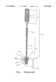
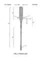
- FIGS. 1 and 2 A top-helical type antenna of the prior art is illustrated in FIGS. 1 and 2.
- FIG. 1 depicts a cross-sectional view of a prior art top-helical type antenna, wherein a helical antenna element 1 of an electrically conductive metal wire such as copper and a copper alloy is wound in coil form, a bobbin 2 is made of insulating polymeric resin and a feeding fixture 3 is made of electrically conductive metal.
- the helical antenna element 1 is wound on the bobbin 2 and is electrically connected at its lower end to the feeding fixture 3.
- a cover 4 of insulating resin encloses helical antenna 5.
- a conductor 1 made of electrically conductive metal is disposed within a resin-insulated tube 7 that forms a sleeve on an outer surface of the conductor 6.
- Conductor 6 is also electrically connected at a lower end to stopper 8, also made of electrically conductive metal, to comprise a whip antenna 9.
- Helical antenna 5 is joined at its lower end to the upper end of whip antenna 9 by insulator 10.
- An antenna holder 11 made of electrically conductive material is provided with a through hole 11A at its center, and an outer periphery having threads 11B.
- the whip antenna 9 is inserted into the through hole 11A, and an outer surface of the stopper 8 contacts with an inner surface of the through hole 11A via a spring 12 fitted within the through hole 11A.
- This top-helical type antenna 14 is mounted to an enclosure 16 of wireless transmission equipment 15 by feeding nut 13 screwed into the threads 11B of the antenna holder 11.
- Radio waves are transmitted and received by the whip antenna 9 that is electrically connected through contact stopper 8 with the antenna holder 11 fitted to the wireless transmission equipment 15, as the top-helical type antenna 14 is extended.
- the stopper 8 of the antenna 9 separates from the antenna holder 11, and the feeding fixture 3 of the helical antenna 5 makes contact with the antenna holder 11 for electrical connection, so that the radio waves are transmitted and received by the helical antenna 5.
- prior art top-helical type antennas have a problem in that the impedance characteristic properly corresponding to the objective frequency band of radio waves is not easily obtainable due to winding diameters and winding pitches that are subject to dimensional dispersion during winding on the bobbin 2. This problem occurs because the helical antenna element 1 of the helical antenna 5 comprises a conductive metal wire wound in a coil form.
- An object of the present invention is to resolve the above-mentioned problem of prior art top-helical type antenna, and to provide a helical antenna having helical coil elements that are not likely to deform, easy to assemble and are less expensive than previous top-helical type antennas.
- a helical coil of the present invention comprises one of a plurality of substantially U-shaped or substantially V-shaped branch portions made of a thin metallic sheet material with the branch portions continuously connected such that their open ends inversely alternate. Each turn of the coil is formed by alternately curving the branch portions toward an obverse side and then a reverse side of the metallic sheet.
- a method of producing the helical coil comprises continuously die-cutting coil members on a belt-shaped strip of an electrically conductive metallic sheet wherein the coil member comprises one of a plurality of either substantially U-shaped or substantially V-shaped branch portions;
- This invention provides a helical antenna having a coil element that is not likely to deform, is easy to assemble and is less expensive than the helical coil antennas of the prior art.
- FIG. 1 is a cross-sectional view of a conventional top-helical type antenna
- FIG. 2 is a cross-sectional view of the conventional top-helical type antenna stored within an enclosure of wireless transmission equipment
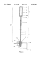
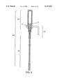
- FIG. 3 is a cross-sectional view of a top-helical type antenna of a first embodiment of the present invention
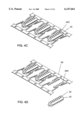
- FIG. 4A is a perspective view of a helical coil member of the present invention after the die-cutting process
- FIG. 4B is a perspective view of the helical coil member of the present invention after the press forming process
- FIG. 4C is a perspective view of the helical coil member of the present invention after outsert-injection molding
- FIG. 4D is a perspective view of the helical coil member of the present invention after shearing off of linkage portions to a electrically conductive metallic sheet;
- FIG. 5 is a cross-sectional view of the top-helical type antenna of the first embodiment of the present invention with the antenna stored within an enclosure of wireless transmission equipment;
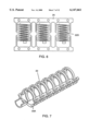
- FIG. 6 is a plan view of the helical coil member of another embodiment of the present invention.
- FIG. 7 is a perspective view of a helical antenna element of another embodiment of the present invention.
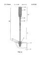
- FIG. 8 is a cross-sectional view of the top-helical type antenna of a second embodiment of the present invention.
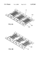
- FIGS. 9A through 9D are perspective views depicting another method of producing the helical antenna of the present invention.
- FIG. 10 is a cross-sectional view of the top-helical type antenna of the present invention with the antenna stored within the enclosure of wireless transmission equipment;
- FIGS. 11A through 11D are cross-sectional views of another embodiment of the top-helical type antenna of another embodiment of the present invention.
- FIG. 3 depicts a top-helical type antenna 25 of the present invention having a whip antenna 9 comprising a conductor 6 electrically connected to a stopper 8, and a tube 7 covering an outer periphery of the conductor 6.
- the top end of the whip antenna 9 is joined with a lower end of the helical antenna 21 through an insulator 10.
- An outer periphery of the stopper 8 of the whip antenna 9 is inserted into through hole 11A of an antenna holder 11 and is in contact with an inner periphery of the through hole 11A.
- Antenna holder 11 is fitted in an enclosure 16 of a wireless transmission equipment 15 by threads 11B.
- a helical antenna element 22 of the helical antenna 21 is made of an electrically conductive metallic sheet.
- Helical antenna element 22 is in a coil shape formed of an electrically conductive metallic sheet such as copper and copper alloys and is electrically connected at its connecting part 22A to a conductive feeding fixture 3.
- An inner periphery is outsert-injection molded with an insulating resin to form a bobbin 23, and an outer periphery is enclosed with a cover 24 of insulating resin formed by insert-injection molding.
- helical coil members 22B in flat form are die-cut consecutively on a belt-shaped strip of electrically conductive metallic sheet 26, as shown in FIG. 4A.
- the helical coil member 22B is shaped so that a plurality of substantially U-shaped branch portions and substantially inverse U-shaped branch portions are lined alternately.
- the substantially U-shaped branch portions and the substantially inverse U-shaped branch portions are connected to form W-shaped letters with connection to the metallic sheet 26 held only by linkage portions 26A at opposing sides.
- the substantially U-shaped branch portions are connected continuously in a manner to place their open ends alternately inversely.
- the helical coil member 22B is S-shaped by uniting the adjoining branch portion of the adjoining U-shaped parts and the branch portions of the inverted U-shaped parts, or having a shape that is configured by a plural number of parts of unitary shape having a linkage portion 26A formed at a bottom of each U-shaped part linked successively in a direction orthogonal to the branch portions of the U-shaped part.
- a plurality of helical coil members 22C is formed in a coil form along with connecting parts 22A, as shown in FIG.
- a bobbin 23 for connecting each turn of the helical coil member 22C is then formed by outsert-injection molding of electrically nonconductive material such as an insulating resin to cover an outer periphery of the helical coil member 22C, including the linkage portions 26A, except for a part of the helical coil member 22C that is exposed as shown in FIG. 4C.
- the helical antenna element 22 with the bobbin 23 molded into one body is completed by shearing off the linkage portions 26A from the electrically conductive metallic sheet 26.
- the helical antenna 21 is completed when the cover 24 is formed with an electrically nonconductive material such as an insulating resin to enclose the periphery after the helical antenna element 22 is connected with a conductive feeding fixture 3.
- Transmitting and receiving radio waves by the top-helical type antenna 25 of the above structure is carried out as described below.
- the top-helical type antenna 25 When the top-helical type antenna 25 is extended as shown in FIG. 3, radio waves are transmitted and received by the whip antenna 9 that is electrically connected through the stopper 8 in contact with the antenna holder 11 fitted to the wireless transmission equipment 15.
- the whip antenna 9 when the whip antenna 9 is retracted within the wireless transmission equipment 15 as shown in FIG. 5, the radio waves are transmitted and received by the helical antenna 21 that is electrically connected through the feeding fixture 3 in contact with the antenna holder 11.
- the operation here is same as that of the prior art.
- the present embodiment forms the helical coil members 22C consecutively on a belt-shaped strip of the electrically conductive metallic sheet 26 by die cutting and press work. These helical coil members are then sheared off at the linkage portions 26A from the conductive metallic sheet 26 after being outsert-injection molded with an electrically nonconductive material, such as an insulating resin, to form the bobbin 23.
- the helical antenna element 22 and the bobbin 23 are thus integrated into one piece.
- This helical antenna element 22 is then enclosed by a cover 24 constructed of an electrically nonconductive material such as an insulating resin around the outer periphery to form the helical antenna 21. Accordingly, the invention provides a helical antenna element 22 that is easy to produce but difficult to deform, has a stable impedance-to-frequency characteristic, and is easy to handle when assembling into an antenna.
- the shape of die-cutting the helical coil member 22B on the belt-shaped strip of electrically conductive metallic sheet 26 has been described as to be substantially U-shaped as shown in FIG. 4A, it may be die-cut in substantially V-shaped form as shown by the helical coil member 22D in FIG. 6.
- the substantially V-shaped branch portions are connected continuously in a manner to place their open ends alternately inversely.
- the bobbin 23 is molded to cover the outer periphery of the helical coil member 22C except for a part, and a space inside the coil member 22C is filled with the insulating resin.
- the same effect is attained and the weight is lightened by molding a bobbin 23A for joining only part of the turns in the coil portion of the helical antenna elements 22 so as not to permit the resin to flow into other parts, as shown in FIG. 7.
- a cross-section of each turn in the coil portion of the helical antenna element 22 need not be flat. If the element 22 is pressed in a manner to make the cross-section convex toward the outside as shown in FIG. 3, for example, rigidity of the coil is increased so as to increase a resistance against deformation.
- FIG. 8 is a cross-sectional view of a top-helical type antenna using a helical antenna of a second embodiment of the present invention.
- the helical antenna 31 differs from that of the first embodiment in that it is provided with a conductive feeding part 33 at a lower end of the helical antenna element 32, whereas the other points remain unchanged such that a lower end of the helical antenna 31 is attached to an upper end of the whip antenna 9 via an insulator.
- the whip antenna 9 is inserted into a through hole 11A of the antenna holder 11 fitted within the enclosure 16 of the wireless transmission equipment 15, and the helical antenna element 32 is made of an electrically conductive metallic sheet.
- the conductive feeding part 33 is provided with the helical antenna 32 in one body projecting in an axial direction from one end of a cover 34 of an insulating resin that is insert-injection molded for enclosing the helical antenna element 32.
- An insulating part 35 of the insulating resin is formed in a coupling portion between the helical antenna 31 and the whip antenna 9.
- helical coil member 32A and conductive feeding part member 33A are in a flat form and die-cut, wherein the helical coil member 32A is shaped so that a plurality of substantially U-shaped branch portions and nearly substantially U-shaped branch portions are lined alternately.
- the substantially U-shaped branch portions and the substantially inverse U-shaped branch portions are connected to form W-shaped letters with connection to a belt-shaped strip of electrically conductive metallic sheet 37 being held only by linkage portions 37A at opposing sides, as shown in FIG. 9A.
- the substantially U-shaped branch portions are connected continuously in a manner to place their open ends alternately inversely.
- the U-shaped branch portions are pressed to configure helical coil member 32B in a coil form by curving the branch portions of the coil member in a nearly circularly-shaped arc toward an obverse side and a reverse side of the metallic sheet alternatively and conductive feeding part 33 in a cylindrical shape.
- An insulating resin is then outsert-injection molded to form a cover 34 for enclosing the helical coil member 32B and the insulating part 35 for connection to the conductive feeding part 33 as shown in FIG. 9C.
- the helical antenna 31 comprising the helical antenna element 32 enclosed by the cover 34 is completed after shearing off the linkage portions 37A from the electrically conductive metallic sheet 37 as shown in FIG. 9D. If the molding is done in a manner to make an inside of the helical antenna element 32 hollow, that is, to allow the molding material to flow in between turns of the coil, the material is saved and the weight is reduced while maintaining a strong integrity between the turns of the coil.
- Transmitting and receiving radio waves by the top-helical type antenna 36 of the above structure is carried out as described below.
- radio waves are transmitted and received by the whip antenna 9 that is electrically connected through the stopper 8 in contact with the antenna holder 11 fitted to the wireless transmission equipment 15, when the antenna 36 is stretched as shown in FIG. 8.
- the radio waves are transmitted and received by the helical antenna 31 that is electrically connected through the conductive feeding part 33 contacting directly with an inner periphery of the through hole 11A of the antenna holder 11.
- the present embodiment forms the cover 34 and the insulating part 35 at the same time by outsert-injection molding an electrically nonconductive material such as an insulating resin after the helical antenna element 32 and the conductive feeding part 33 are formed by die cutting and press work on the belt-shaped strip of electrically conductive metallic sheet 37. Also, the cover 34 connects portions between turns of the coil when the cover encloses the outer periphery of the helical coil member 32B.
- the helical antenna 31 formed with the cover 34 and the insulating part 35 can be produced consecutively when producing the helical antenna elements 32, so there is formed a helical antenna element 32 that is not likely to deform, has a stable impedance-to-frequency characteristic and is easy to assemble, in addition to reducing the costs of construction.
- an electrical connection to the antenna holder 11 is made by the conductive feeding part 33 that is provided at a lower end of the helical antenna element 32 as an integral part and projects in an axial direction from one end of the cover 34.
- a part such as the feeding fixture for electrically connecting the antenna holder 11 is omitted, thereby providing a top-helical type antenna that is easier to assemble and less expensive than similar prior art antennas.
- a top-helical type antenna of this type in which an upper end of the whip antenna 9 is joined to a lower end of the helical antenna 21 or 31 with insulation between them, can be formed.
- this configuration is not exclusive and the present invention may be embodied in an antenna in which a conductor 6 of the whip antenna 9 is electrically connected with a feeding fixture 3A of the helical antenna 40 as shown in FIG. 11A.
- the present invention may also be practiced in a fixed helical type antenna where only a helical antenna 41 is mounted on the outside or the inside of the wireless transmission equipment 15 as shown in FIG. 11B and FIG.
Landscapes
- Engineering & Computer Science (AREA)
- Computer Networks & Wireless Communication (AREA)
- Details Of Aerials (AREA)
- Support Of Aerials (AREA)
Applications Claiming Priority (2)
| Application Number | Priority Date | Filing Date | Title |
|---|---|---|---|
| JP9-196702 | 1997-07-23 | ||
| JP19670297A JP3669117B2 (ja) | 1997-07-23 | 1997-07-23 | ヘリカルアンテナ及びその製造方法 |
Publications (1)
| Publication Number | Publication Date |
|---|---|
| US6147661A true US6147661A (en) | 2000-11-14 |
Family
ID=16362173
Family Applications (1)
| Application Number | Title | Priority Date | Filing Date |
|---|---|---|---|
| US09/120,877 Expired - Fee Related US6147661A (en) | 1997-07-23 | 1998-07-23 | Helical coil, method of producing same and helical antenna using same |
Country Status (4)
| Country | Link |
|---|---|
| US (1) | US6147661A (de) |
| EP (1) | EP0893841B1 (de) |
| JP (1) | JP3669117B2 (de) |
| DE (1) | DE69832852T2 (de) |
Cited By (8)
| Publication number | Priority date | Publication date | Assignee | Title |
|---|---|---|---|---|
| US6326928B1 (en) * | 1999-10-26 | 2001-12-04 | Matsushita Electric Industrial Co., Ltd. | Antenna fixing method and device |
| US6404406B2 (en) * | 1998-08-07 | 2002-06-11 | Siemens Aktiengesellschaft | Antenna having a wide bandwidth |
| US6448934B1 (en) * | 2001-06-15 | 2002-09-10 | Hewlett-Packard Company | Multi band antenna |
| US20030174091A1 (en) * | 2002-03-15 | 2003-09-18 | Mendolia Greg S. | Method of manufacturing antennas using micro-insert-molding techniques |
| US20030174096A1 (en) * | 2002-03-15 | 2003-09-18 | Mendolia Greg S. | Method of mechanically tuning antennas for low-cost volume production |
| US20040244187A1 (en) * | 2003-03-31 | 2004-12-09 | Filtronic Lk Oy | Method for producing antenna components |
| US20110030198A1 (en) * | 2009-08-10 | 2011-02-10 | Samsung Electro-Mechanics Co., Ltd. | Method and device for manufacturing antenna pattern frame |
| DE102024124766A1 (de) * | 2024-08-29 | 2026-03-05 | Seamless Energy Technologies Gesellschaft mbH | Verfahren und Vorrichtung zum Herstellen einer induktiven Ladeeinheit, Träger sowie induktive Ladeeinheit |
Families Citing this family (23)
| Publication number | Priority date | Publication date | Assignee | Title |
|---|---|---|---|---|
| EP1029646A1 (de) * | 1999-02-16 | 2000-08-23 | Gabriel Technologies, Inc. | Zweistufiges Spritzgiessverfahren zur Herstellung von Wendelantennen |
| WO2000065684A2 (de) * | 1999-04-21 | 2000-11-02 | Siemens Aktiengesellschaft | Antenne, verwendung einer derartigen antenne und verfahren zur herstellung einer derartigen antenne |
| DE19918028A1 (de) | 1999-04-21 | 2000-11-02 | Siemens Ag | Halbleiter-Bauelement |
| DE60018878T2 (de) | 1999-05-21 | 2005-07-28 | Matsushita Electric Industrial Co., Ltd., Kadoma | Antenne für mobile kommunikation und mobiles kommunikationsgerät mit einer derartigen antenne |
| JP3788115B2 (ja) * | 1999-07-23 | 2006-06-21 | 松下電器産業株式会社 | アンテナ装置の製造方法 |
| JP4147696B2 (ja) | 1999-09-16 | 2008-09-10 | 松下電器産業株式会社 | アンテナ装置およびそれを用いた通信端末 |
| WO2001056112A1 (de) * | 2000-01-25 | 2001-08-02 | Siemens Aktiengesellschaft | Antenne für ein kommunikationsgerät |
| JP3835128B2 (ja) * | 2000-06-09 | 2006-10-18 | 松下電器産業株式会社 | アンテナ装置 |
| JP2002319813A (ja) * | 2000-07-24 | 2002-10-31 | Furukawa Electric Co Ltd:The | チップアンテナ及びその製造方法 |
| US6630906B2 (en) | 2000-07-24 | 2003-10-07 | The Furukawa Electric Co., Ltd. | Chip antenna and manufacturing method of the same |
| WO2002013312A1 (en) * | 2000-08-04 | 2002-02-14 | Matsushita Electric Industrial Co., Ltd. | Antenna device and radio communication device comprising the same |
| JP3884281B2 (ja) * | 2000-12-26 | 2007-02-21 | 古河電気工業株式会社 | 小型アンテナ及びその製造方法 |
| EP1221738A3 (de) * | 2000-12-27 | 2002-10-23 | The Furukawa Electric Co., Ltd. | Kleine Antenne und Verfahren zu deren Herstellung |
| JP2002280819A (ja) * | 2000-12-27 | 2002-09-27 | Furukawa Electric Co Ltd:The | 小型アンテナの製造方法 |
| TW513827B (en) | 2001-02-07 | 2002-12-11 | Furukawa Electric Co Ltd | Antenna apparatus |
| JP2002344221A (ja) * | 2001-04-27 | 2002-11-29 | Molex Inc | ヘリカルアンテナとその製造方法 |
| EP1258945A3 (de) | 2001-05-16 | 2003-11-05 | The Furukawa Electric Co., Ltd. | Linienförmige Antenne |
| DE60209278T2 (de) | 2001-06-25 | 2006-10-12 | The Furukawa Electric Co., Ltd. | Chip-Antenne und Herstellungsverfahren einer solchen Antenne |
| ATE325437T1 (de) * | 2001-12-07 | 2006-06-15 | Hirschmann Electronics Gmbh | Antenne, insbesondere mobilfunkantenne, mit einer zentrierhilfe bei ihrer herstellung |
| JP2003218620A (ja) * | 2002-01-24 | 2003-07-31 | Hitachi Cable Ltd | 平板アンテナの製造方法 |
| FR2884650B1 (fr) * | 2005-04-18 | 2007-10-12 | Valeo Electronique Sys Liaison | Antenne |
| JP4819626B2 (ja) * | 2006-09-08 | 2011-11-24 | パナソニック株式会社 | アンテナモジュールとこれを用いたカプセル内視鏡システム及びアンテナモジュールの製造方法 |
| CN105140625B (zh) * | 2015-09-18 | 2018-08-28 | 深圳市信维通信股份有限公司 | 一种天线的制造方法及天线结构 |
Citations (14)
| Publication number | Priority date | Publication date | Assignee | Title |
|---|---|---|---|---|
| JPS58137206A (ja) * | 1982-02-09 | 1983-08-15 | Sony Corp | インダクタンス素子 |
| US4435713A (en) * | 1981-11-20 | 1984-03-06 | Motorola, Inc. | Whip antenna construction |
| US4725395A (en) * | 1985-01-07 | 1988-02-16 | Motorola, Inc. | Antenna and method of manufacturing an antenna |
| US4862184A (en) * | 1987-02-06 | 1989-08-29 | George Ploussios | Method and construction of helical antenna |
| WO1993000721A1 (de) * | 1991-06-27 | 1993-01-07 | Siemens Aktiengesellschaft | Planare mäander-antenne |
| JPH05347507A (ja) * | 1992-06-12 | 1993-12-27 | Junkosha Co Ltd | アンテナ |
| US5341149A (en) * | 1991-03-25 | 1994-08-23 | Nokia Mobile Phones Ltd. | Antenna rod and procedure for manufacturing same |
| GB2282705A (en) * | 1993-09-09 | 1995-04-12 | Mitsubishi Electric Corp | Antenna system having plural antenna portions |
| US5479178A (en) * | 1993-05-21 | 1995-12-26 | Samsung Electronics Co., Ltd. | Portable radio antenna |
| US5596797A (en) * | 1995-04-03 | 1997-01-28 | D & M Plastics Corporation | Method and apparatus for making a molded cellular antenna coil |
| WO1997007560A1 (en) * | 1995-08-11 | 1997-02-27 | The Whitaker Corporation | Flexible antenna and method of manufacturing same |
| US5764198A (en) * | 1995-09-25 | 1998-06-09 | Murata Manufacturing Co. Ltd. | Chip antenna |
| US5818398A (en) * | 1995-05-17 | 1998-10-06 | Murata Mfg. Co., Ltd. | Surface mounting type antenna system |
| US5892490A (en) * | 1996-11-07 | 1999-04-06 | Murata Manufacturing Co., Ltd. | Meander line antenna |
Family Cites Families (14)
| Publication number | Priority date | Publication date | Assignee | Title |
|---|---|---|---|---|
| JPS5430460A (en) * | 1977-08-11 | 1979-03-06 | Murata Manufacturing Co | Method of making coil |
| JPH01107106U (de) * | 1988-01-12 | 1989-07-19 | ||
| JPH04215412A (ja) * | 1990-12-13 | 1992-08-06 | Sony Corp | インダクタ及びモールドインダクタ |
| JP3054231B2 (ja) * | 1991-05-15 | 2000-06-19 | ティーディーケイ株式会社 | コイル装置 |
| JP2719857B2 (ja) * | 1991-07-11 | 1998-02-25 | シャープ株式会社 | 4線式バックファイヤヘリカルアンテナ |
| JP2867202B2 (ja) * | 1993-03-02 | 1999-03-08 | 株式会社ヨコオ | アンテナ |
| JPH0722244A (ja) * | 1993-06-18 | 1995-01-24 | Nippon Mektron Ltd | 共振回路ユニット |
| JPH0745441A (ja) * | 1993-07-29 | 1995-02-14 | Nippon Mektron Ltd | 共振回路ユニットおよびその製造方法 |
| JPH07240616A (ja) * | 1994-02-28 | 1995-09-12 | Matsushita Electric Ind Co Ltd | ヘリカルアンテナ及び無線電話機 |
| JPH07235820A (ja) * | 1994-02-21 | 1995-09-05 | Nippon Antenna Co Ltd | アンテナ |
| JPH08195618A (ja) * | 1995-01-13 | 1996-07-30 | Citizen Watch Co Ltd | 携帯型電子機器のアンテナ構造 |
| JPH09107214A (ja) * | 1995-10-11 | 1997-04-22 | Tokin Corp | 分離型アンテナ |
| JP3179696B2 (ja) * | 1996-01-19 | 2001-06-25 | エスエムケイ株式会社 | アンテナ装置 |
| JPH09275309A (ja) * | 1996-04-05 | 1997-10-21 | Nippon Antenna Co Ltd | 携帯機器用アンテナ |
-
1997
- 1997-07-23 JP JP19670297A patent/JP3669117B2/ja not_active Expired - Fee Related
-
1998
- 1998-07-23 US US09/120,877 patent/US6147661A/en not_active Expired - Fee Related
- 1998-07-23 EP EP98113808A patent/EP0893841B1/de not_active Expired - Lifetime
- 1998-07-23 DE DE69832852T patent/DE69832852T2/de not_active Expired - Fee Related
Patent Citations (15)
| Publication number | Priority date | Publication date | Assignee | Title |
|---|---|---|---|---|
| US4435713A (en) * | 1981-11-20 | 1984-03-06 | Motorola, Inc. | Whip antenna construction |
| JPS58137206A (ja) * | 1982-02-09 | 1983-08-15 | Sony Corp | インダクタンス素子 |
| US4725395A (en) * | 1985-01-07 | 1988-02-16 | Motorola, Inc. | Antenna and method of manufacturing an antenna |
| US4862184A (en) * | 1987-02-06 | 1989-08-29 | George Ploussios | Method and construction of helical antenna |
| US5341149A (en) * | 1991-03-25 | 1994-08-23 | Nokia Mobile Phones Ltd. | Antenna rod and procedure for manufacturing same |
| WO1993000721A1 (de) * | 1991-06-27 | 1993-01-07 | Siemens Aktiengesellschaft | Planare mäander-antenne |
| JPH05347507A (ja) * | 1992-06-12 | 1993-12-27 | Junkosha Co Ltd | アンテナ |
| US5479178A (en) * | 1993-05-21 | 1995-12-26 | Samsung Electronics Co., Ltd. | Portable radio antenna |
| GB2282705A (en) * | 1993-09-09 | 1995-04-12 | Mitsubishi Electric Corp | Antenna system having plural antenna portions |
| US5596797A (en) * | 1995-04-03 | 1997-01-28 | D & M Plastics Corporation | Method and apparatus for making a molded cellular antenna coil |
| US5648788A (en) * | 1995-04-03 | 1997-07-15 | D & M Plastics Corporation | Molded cellular antenna coil |
| US5818398A (en) * | 1995-05-17 | 1998-10-06 | Murata Mfg. Co., Ltd. | Surface mounting type antenna system |
| WO1997007560A1 (en) * | 1995-08-11 | 1997-02-27 | The Whitaker Corporation | Flexible antenna and method of manufacturing same |
| US5764198A (en) * | 1995-09-25 | 1998-06-09 | Murata Manufacturing Co. Ltd. | Chip antenna |
| US5892490A (en) * | 1996-11-07 | 1999-04-06 | Murata Manufacturing Co., Ltd. | Meander line antenna |
Non-Patent Citations (4)
| Title |
|---|
| Patent Abstract of Japan; vol. 7, No. 251 (E 209); Nov. 8, 1983 & JP 58 137206 A (Sony); Aug. 15, 1983 *abstract*. * |
| Patent Abstract of Japan; vol. 7, No. 251 (E-209); Nov. 8, 1983 & JP 58 137206 A (Sony); Aug. 15, 1983 *abstract*. |
| Patent Abstracts of Japan; vol. 18, No. 188 (E 1532); Mar. 31, 1994 & JP 05 347507 A (Junkosha); Dec. 27, 1993 *abstract*. * |
| Patent Abstracts of Japan; vol. 18, No. 188 (E-1532); Mar. 31, 1994 & JP 05 347507 A (Junkosha); Dec. 27, 1993 *abstract*. |
Cited By (12)
| Publication number | Priority date | Publication date | Assignee | Title |
|---|---|---|---|---|
| US6404406B2 (en) * | 1998-08-07 | 2002-06-11 | Siemens Aktiengesellschaft | Antenna having a wide bandwidth |
| US6326928B1 (en) * | 1999-10-26 | 2001-12-04 | Matsushita Electric Industrial Co., Ltd. | Antenna fixing method and device |
| US6448934B1 (en) * | 2001-06-15 | 2002-09-10 | Hewlett-Packard Company | Multi band antenna |
| US20030174091A1 (en) * | 2002-03-15 | 2003-09-18 | Mendolia Greg S. | Method of manufacturing antennas using micro-insert-molding techniques |
| US20030174096A1 (en) * | 2002-03-15 | 2003-09-18 | Mendolia Greg S. | Method of mechanically tuning antennas for low-cost volume production |
| US6822609B2 (en) | 2002-03-15 | 2004-11-23 | Etenna Corporation | Method of manufacturing antennas using micro-insert-molding techniques |
| US6839029B2 (en) | 2002-03-15 | 2005-01-04 | Etenna Corporation | Method of mechanically tuning antennas for low-cost volume production |
| US20040244187A1 (en) * | 2003-03-31 | 2004-12-09 | Filtronic Lk Oy | Method for producing antenna components |
| US7237318B2 (en) * | 2003-03-31 | 2007-07-03 | Pulse Finland Oy | Method for producing antenna components |
| US20110030198A1 (en) * | 2009-08-10 | 2011-02-10 | Samsung Electro-Mechanics Co., Ltd. | Method and device for manufacturing antenna pattern frame |
| US8943679B2 (en) * | 2009-08-10 | 2015-02-03 | Samsung Electro-Mechanics Co., Ltd. | Device for manufacturing antenna pattern frame for built-in antenna |
| DE102024124766A1 (de) * | 2024-08-29 | 2026-03-05 | Seamless Energy Technologies Gesellschaft mbH | Verfahren und Vorrichtung zum Herstellen einer induktiven Ladeeinheit, Träger sowie induktive Ladeeinheit |
Also Published As
| Publication number | Publication date |
|---|---|
| DE69832852D1 (de) | 2006-01-26 |
| DE69832852T2 (de) | 2006-06-22 |
| JP3669117B2 (ja) | 2005-07-06 |
| EP0893841A1 (de) | 1999-01-27 |
| EP0893841B1 (de) | 2005-12-21 |
| JPH1141019A (ja) | 1999-02-12 |
Similar Documents
| Publication | Publication Date | Title |
|---|---|---|
| EP0893841B1 (de) | Wendelantenne und Verfahren zu deren Herstellung | |
| KR100356196B1 (ko) | 2주파 대응 안테나 장치 및 이를 사용한 이동 통신기기 | |
| EP0790666A1 (de) | Kombinierte Struktur einer Helixantenne und einer dielektrischen Platte | |
| US6801166B2 (en) | Planar antenna | |
| JP3788115B2 (ja) | アンテナ装置の製造方法 | |
| US4205319A (en) | Flexible dipole antenna for hand-held two-way radio | |
| JPH09107223A (ja) | アンテナ | |
| JPH10173430A (ja) | 2周波数アンテナ | |
| JPWO1999048169A1 (ja) | アンテナ装置およびそれを用いた移動体通信機器 | |
| KR20020035573A (ko) | 안테나 및 그것을 이용한 무선 장치 | |
| AU7863798A (en) | Multi-band antenna suitable for use in a mobile radio device | |
| US6639562B2 (en) | GSM/DCS stubby antenna | |
| US6628241B1 (en) | Antenna device and communication terminal comprising the same | |
| US5825334A (en) | Flexible antenna and method of manufacturing same | |
| US3781899A (en) | Flexible helical spring antenna | |
| JPH1188031A (ja) | マルチバンドアンテナ | |
| US20040119657A1 (en) | Stubby, multi-band, antenna having a large-diameter high frequency radiating/receiving element surrounding a small-diameter low frequency radiating/receiving element | |
| EP1635419B1 (de) | Antenne und Funkkommunikationsendgerät mit dieser Antenne | |
| US20030088968A1 (en) | Helical antenna and method of making the same | |
| CN100388561C (zh) | 双频带天线 | |
| US6246372B1 (en) | Extendable whip antenna | |
| US6268830B1 (en) | Antenna and its manufacturing method | |
| GB2344938A (en) | A multiple band, multiple co-axial element antenna | |
| JP2003037418A (ja) | マルチバンド・アンテナ | |
| JP3163480B2 (ja) | ホイップアンテナ及びその製造方法 |
Legal Events
| Date | Code | Title | Description |
|---|---|---|---|
| AS | Assignment |
Owner name: MATSUSHITA ELECTRIC INDUSTRIAL CO., LTD., JAPAN Free format text: ASSIGNMENT OF ASSIGNORS INTEREST;ASSIGNORS:NAKAGAWA, YOSHINOBU;INATSUGU, SUSUMU;YAMABAYASHI, MASAAKI;AND OTHERS;REEL/FRAME:009476/0168 Effective date: 19980909 |
|
| FEPP | Fee payment procedure |
Free format text: PAYOR NUMBER ASSIGNED (ORIGINAL EVENT CODE: ASPN); ENTITY STATUS OF PATENT OWNER: LARGE ENTITY |
|
| FPAY | Fee payment |
Year of fee payment: 4 |
|
| FPAY | Fee payment |
Year of fee payment: 8 |
|
| REMI | Maintenance fee reminder mailed | ||
| LAPS | Lapse for failure to pay maintenance fees | ||
| STCH | Information on status: patent discontinuation |
Free format text: PATENT EXPIRED DUE TO NONPAYMENT OF MAINTENANCE FEES UNDER 37 CFR 1.362 |
|
| FP | Lapsed due to failure to pay maintenance fee |
Effective date: 20121114 |