US6148782A - Airflow device - Google Patents
Airflow device Download PDFInfo
- Publication number
- US6148782A US6148782A US09/194,763 US19476398A US6148782A US 6148782 A US6148782 A US 6148782A US 19476398 A US19476398 A US 19476398A US 6148782 A US6148782 A US 6148782A
- Authority
- US
- United States
- Prior art keywords
- air
- inner tube
- intake device
- air intake
- flow
- Prior art date
- Legal status (The legal status is an assumption and is not a legal conclusion. Google has not performed a legal analysis and makes no representation as to the accuracy of the status listed.)
- Expired - Fee Related
Links
- 238000002485 combustion reaction Methods 0.000 claims description 16
- 230000008878 coupling Effects 0.000 claims description 4
- 238000010168 coupling process Methods 0.000 claims description 4
- 238000005859 coupling reaction Methods 0.000 claims description 4
- 238000007789 sealing Methods 0.000 claims description 4
- 238000011144 upstream manufacturing Methods 0.000 claims 7
- 230000000903 blocking effect Effects 0.000 claims 2
- 230000007246 mechanism Effects 0.000 abstract 1
- 238000013016 damping Methods 0.000 description 11
- 230000001629 suppression Effects 0.000 description 9
- 230000009471 action Effects 0.000 description 6
- 230000008859 change Effects 0.000 description 5
- 230000009467 reduction Effects 0.000 description 5
- 230000005284 excitation Effects 0.000 description 3
- 230000003993 interaction Effects 0.000 description 3
- 230000010349 pulsation Effects 0.000 description 3
- 230000006978 adaptation Effects 0.000 description 2
- 230000001419 dependent effect Effects 0.000 description 2
- 239000000446 fuel Substances 0.000 description 2
- 238000005457 optimization Methods 0.000 description 2
- 238000006243 chemical reaction Methods 0.000 description 1
- 230000003292 diminished effect Effects 0.000 description 1
- 210000005069 ears Anatomy 0.000 description 1
- 230000000694 effects Effects 0.000 description 1
- 230000006872 improvement Effects 0.000 description 1
- 239000000463 material Substances 0.000 description 1
- 230000007935 neutral effect Effects 0.000 description 1
- 238000004904 shortening Methods 0.000 description 1
Images
Classifications
-
- F—MECHANICAL ENGINEERING; LIGHTING; HEATING; WEAPONS; BLASTING
- F02—COMBUSTION ENGINES; HOT-GAS OR COMBUSTION-PRODUCT ENGINE PLANTS
- F02M—SUPPLYING COMBUSTION ENGINES IN GENERAL WITH COMBUSTIBLE MIXTURES OR CONSTITUENTS THEREOF
- F02M35/00—Combustion-air cleaners, air intakes, intake silencers, or induction systems specially adapted for, or arranged on, internal-combustion engines
- F02M35/12—Intake silencers ; Sound modulation, transmission or amplification
- F02M35/1205—Flow throttling or guiding
- F02M35/1222—Flow throttling or guiding by using adjustable or movable elements, e.g. valves, membranes, bellows, expanding or shrinking elements
-
- F—MECHANICAL ENGINEERING; LIGHTING; HEATING; WEAPONS; BLASTING
- F02—COMBUSTION ENGINES; HOT-GAS OR COMBUSTION-PRODUCT ENGINE PLANTS
- F02B—INTERNAL-COMBUSTION PISTON ENGINES; COMBUSTION ENGINES IN GENERAL
- F02B27/00—Use of kinetic or wave energy of charge in induction systems, or of combustion residues in exhaust systems, for improving quantity of charge or for increasing removal of combustion residues
- F02B27/005—Oscillating pipes with charging achieved by arrangement, dimensions or shapes of intakes pipes or chambers; Ram air pipes
- F02B27/006—Oscillating pipes with charging achieved by arrangement, dimensions or shapes of intakes pipes or chambers; Ram air pipes of intake runners
-
- F—MECHANICAL ENGINEERING; LIGHTING; HEATING; WEAPONS; BLASTING
- F02—COMBUSTION ENGINES; HOT-GAS OR COMBUSTION-PRODUCT ENGINE PLANTS
- F02B—INTERNAL-COMBUSTION PISTON ENGINES; COMBUSTION ENGINES IN GENERAL
- F02B27/00—Use of kinetic or wave energy of charge in induction systems, or of combustion residues in exhaust systems, for improving quantity of charge or for increasing removal of combustion residues
- F02B27/02—Use of kinetic or wave energy of charge in induction systems, or of combustion residues in exhaust systems, for improving quantity of charge or for increasing removal of combustion residues the systems having variable, i.e. adjustable, cross-sectional areas, chambers of variable volume, or like variable means
- F02B27/0205—Use of kinetic or wave energy of charge in induction systems, or of combustion residues in exhaust systems, for improving quantity of charge or for increasing removal of combustion residues the systems having variable, i.e. adjustable, cross-sectional areas, chambers of variable volume, or like variable means characterised by the charging effect
- F02B27/0215—Oscillating pipe charging, i.e. variable intake pipe length charging
-
- F—MECHANICAL ENGINEERING; LIGHTING; HEATING; WEAPONS; BLASTING
- F02—COMBUSTION ENGINES; HOT-GAS OR COMBUSTION-PRODUCT ENGINE PLANTS
- F02B—INTERNAL-COMBUSTION PISTON ENGINES; COMBUSTION ENGINES IN GENERAL
- F02B27/00—Use of kinetic or wave energy of charge in induction systems, or of combustion residues in exhaust systems, for improving quantity of charge or for increasing removal of combustion residues
- F02B27/02—Use of kinetic or wave energy of charge in induction systems, or of combustion residues in exhaust systems, for improving quantity of charge or for increasing removal of combustion residues the systems having variable, i.e. adjustable, cross-sectional areas, chambers of variable volume, or like variable means
- F02B27/0226—Use of kinetic or wave energy of charge in induction systems, or of combustion residues in exhaust systems, for improving quantity of charge or for increasing removal of combustion residues the systems having variable, i.e. adjustable, cross-sectional areas, chambers of variable volume, or like variable means characterised by the means generating the charging effect
- F02B27/0231—Movable ducts, walls or the like
-
- F—MECHANICAL ENGINEERING; LIGHTING; HEATING; WEAPONS; BLASTING
- F02—COMBUSTION ENGINES; HOT-GAS OR COMBUSTION-PRODUCT ENGINE PLANTS
- F02B—INTERNAL-COMBUSTION PISTON ENGINES; COMBUSTION ENGINES IN GENERAL
- F02B27/00—Use of kinetic or wave energy of charge in induction systems, or of combustion residues in exhaust systems, for improving quantity of charge or for increasing removal of combustion residues
- F02B27/02—Use of kinetic or wave energy of charge in induction systems, or of combustion residues in exhaust systems, for improving quantity of charge or for increasing removal of combustion residues the systems having variable, i.e. adjustable, cross-sectional areas, chambers of variable volume, or like variable means
- F02B27/0226—Use of kinetic or wave energy of charge in induction systems, or of combustion residues in exhaust systems, for improving quantity of charge or for increasing removal of combustion residues the systems having variable, i.e. adjustable, cross-sectional areas, chambers of variable volume, or like variable means characterised by the means generating the charging effect
- F02B27/0268—Valves
- F02B27/0273—Flap valves
-
- F—MECHANICAL ENGINEERING; LIGHTING; HEATING; WEAPONS; BLASTING
- F02—COMBUSTION ENGINES; HOT-GAS OR COMBUSTION-PRODUCT ENGINE PLANTS
- F02M—SUPPLYING COMBUSTION ENGINES IN GENERAL WITH COMBUSTIBLE MIXTURES OR CONSTITUENTS THEREOF
- F02M35/00—Combustion-air cleaners, air intakes, intake silencers, or induction systems specially adapted for, or arranged on, internal-combustion engines
- F02M35/12—Intake silencers ; Sound modulation, transmission or amplification
- F02M35/1205—Flow throttling or guiding
- F02M35/1227—Flow throttling or guiding by using multiple air intake flow paths, e.g. bypass, honeycomb or pipes opening into an expansion chamber
-
- Y—GENERAL TAGGING OF NEW TECHNOLOGICAL DEVELOPMENTS; GENERAL TAGGING OF CROSS-SECTIONAL TECHNOLOGIES SPANNING OVER SEVERAL SECTIONS OF THE IPC; TECHNICAL SUBJECTS COVERED BY FORMER USPC CROSS-REFERENCE ART COLLECTIONS [XRACs] AND DIGESTS
- Y02—TECHNOLOGIES OR APPLICATIONS FOR MITIGATION OR ADAPTATION AGAINST CLIMATE CHANGE
- Y02T—CLIMATE CHANGE MITIGATION TECHNOLOGIES RELATED TO TRANSPORTATION
- Y02T10/00—Road transport of goods or passengers
- Y02T10/10—Internal combustion engine [ICE] based vehicles
- Y02T10/12—Improving ICE efficiencies
Definitions
- the invention relates to an air flow device for a unit, for example an internal combustion engine, which requires for its operation a given amount of air, in accordance with the preamble of claim 1 and the parallel independent claim 6.
- an air intake device for an internal combustion engine is disclosed in DE-OS 40 41 786, in which a controllable shut-off means is present in order to vary the opening through which the aspirated air flows.
- the shut-off means is in a transverse channel situated between two intake channels and is opened or closed by commands from an electronic control. The commands are dependent upon the rotational speed of the internal combustion engine and on the temperature of the outside air, which is determined by a temperature sensor.
- cylinder cutout involves changing a 6-cylinder internal combustion engine from 6-cylinder to 3-cylinder operation.
- suction pulse emitted by each of these cylinders in the air intake device remains unchanged in itself, the cyclical interaction of 6 cylinders results in a different kind of pulsation than that of 3 cylinders.
- deep humming sounds are annoying; in view of the space available in a motor vehicle, these low-frequency components can be diminished only by costly reflective sound dampers (e.g., Helmholtz resonators).
- the invention is addressed to the problem of improving in a simple manner an air flow device according to the preamble of claim 1 and of the parallel independent claim 6, such that optimal operating conditions, and especially noise conditions, will prevail in different states of operation of the attached unit.
- the air flow device according to the invention solves the stated problem by the features specified in the characterizing part of claim 1 and of the parallel independent claim 6.
- the air flow device of the invention is advantageous especially due to the fact that, by varying the course of the air flow and the aspiration geometry, an adaptation can be made to various states of operation, as for example when the number of cylinders in an internal combustion engine is varied, especially with regard to the optimization of noise emission.
- the invention describes a flexible system for aspirating various amounts of air, especially in the case of pulsating flow conditions.
- two adjusting devices according to claim 1 it is advantageously possible with one of them to switch the paths of the flow between them and with the other to change sound propagation paths through at least three flow channels consisting for example of flexible tubes.
- a flap in each adjusting device can assume two positions in which, by deflecting the air flow, either a longer and narrower or a shorter and wider flow path and sound propagation path can be created.
- An air flow device contains at the inlet end an air filter, as a rule, with an air intake funnel. These parts form a series-connected Helmholtz resonator whose resonance frequency results from the following formula:
- V Volume of the air filter that follows
- the result is thus a tripling of the resonance frequency by an enlargement of cross section by the parallel opening of the three flow passages and a one-third reduction of the resonance frequency by a lengthening achieved by connecting the three flow channels in tandem.
- the lower value can be at 25 Hz and the upper value at 75 Hz.
- the noise suppression then begins at tones above the frequency of 35 Hz and 106 Hz, respectively.
- valve pivot shafts of the two adjusting devices can be coupled fixedly to one another, so that a simple arrangement results for obtaining the conditions described above.
- the adjusting devices can be placed directly side by side or one over the other, and thus the two pivot shafts of the valve can easily be connected together and require only a single motor for their operation.
- the two valves are spring-biased.
- a third position of the valves is possible, in which only one valve is moved and thus the valves assume different positions. If, for example, only one valve is moved away from the long-and-narrow channel position, the length of the damping channel diminishes by a factor of 3; but the cross-sectional area remains the same. The resonance frequency therefore increases by a factor of ⁇ 3 and, as in the example described above, assumes the value of 43.3 Hz, and thus this intermediate position can be used, for example, for the middle speed range of an internal combustion engine.
- the noise emissions differ considerably in these phases of operation in a preferred application of the invention, namely in the operation of an internal combustion engine with different numbers of cylinders.
- the frequency characteristic of the suction pulses is determined not only by the cylinder pulsed vibration but also by the harmonics; the frequency characteristic of the 6-cylinder engine can be described essentially by the interaction of the sine vibrations of the 6th and 12th harmonic, the amplitudes being definitely smaller than those of the cylinder pulsation.
- the cycle of a 3-cylinder motor vibrates almost exclusively with the sine wave of the 3rd harmonic and the amplitude increases beyond the value of the single pulse; this can amount to a difference in level of the noise emission of 13 decibels.
- the noise emission can be advantageously reduced.
- very loud humming sounds created by full-load operation which in ordinary types of vehicles find a very easy path to the passenger compartment and could reach the ears of the passengers intensified by resonance, are successfully reduced.
- the result is that, for the reduction of noise, in addition to the size of the volume of the air intake apparatus, the dimensions of the so-called acoustic neck in the air intake tube are critical to the noise suppressing action.
- the narrower and longer the tube section is, the lower will be the frequency at which noise suppression begins.
- a lengthening and narrowing of the air intake path can be achieved for better suppression of the lower frequency components.
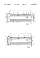
- FIG. 1 shows a cross section through a first embodiment with a tube section of an air intake device with two inner tubes in the initial state;
- FIG. 2 shows a cross section through a tube section of an air intake device with two inner tubes in the switched state
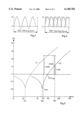
- FIGS. 3 and 4 show the vibrations of a 3-cylinder and a 6-cylinder engine
- FIG. 5 shows a curve of the noise damping effect of an acoustic neck verses the frequency with different numbers of cylinders
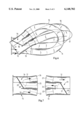
- FIG. 6 shows an additional preferred embodiment showing the principle of the air flow device with three switchable flow channels
- FIG. 7 shows in detail the adjusting devices of FIG. 6 with movable valve flaps in the flow channels.
- FIG. 1 there is shown a first embodiment with a tube 1 of an air intake device for an internal combustion engine here not shown, through which an air stream passes according to arrow 2 and arrows 2.0, 2.1 and 2.2, respectively.
- a first inner tube 3 is affixed to it concentrically.
- An axially displaceable second inner tube 4 extends between this first inner tube 3 and the inner wall of tube 1.
- the second inner tube 4 can be displaced axially until it sealingly contacts a stop plate 5.
- the stop plate 5 here serves also as a mounting for the first inner tube 3.
- the first inner tube 3 has at the bottom end adjacent the stop plate 5 a number of ports 6 through which the aspirated air can flow into the interior of the first inner tube 3 if the second inner tube 4 in FIG. 1 is not pushed down.
- the aspirated air flows parallel through the intermediate spaces 9 and 10 and through the inner tube 3 (arrows 2.0, 2.1 and 2.2).
- the movable inner tube 4 is in the position shown in FIG. 1, which permits a parallel flow through the three tube chambers.
- the length of the flow path is L
- the flow cross section has the value 3 ⁇ A, A being the area contained by the cross section of one of the three tube chambers.
- the second inner tube 4 is pushed down, so that it is in tight contact with the stop plate 5.
- the aspirated air is thus forced to flow through the first intermediate space 9 (arrow 2.3) and is directed at the right end by the sealing plate 8 to the ports 7 and flows back contrary to the air intake direction in the second intermediate space 10 (arrow 2.4).
- the air passes through the ports 6 into the first inner tube and flows according to arrow 2.5.
- a flow path is configured which, from the outside in, measures three times the length of tube section 1.
- the timing of the suction pulses in 3-cylinder operation is shown in FIG. 3, and in 6-cylinder operation in FIG. 4.
- the cycle of the 6-cylinder motor of FIG. 4 shows the interaction of the sine vibrations of the 6th and 12th harmonics of a 720° working cycle, wherein it can be seen that the amplitudes of the resultant vibration are definitely less than those of the individual pulses.
- the 3-cylinder cycle according to FIG. 3 vibrates almost exclusively with the sine vibration of the third harmonic and the amplitude at the same time increases beyond the value of the individual pulse.
- a motor speed of 3000 rpm for example, in 6-cylinder operation there is an undesired frequency of 150 Hz and in 3-cylinder operation it is 75 Hz.
- curves of noise suppression versus frequency in the two states of operation In curve 30 the suppression curve for 6-cylinder operation is shown, and in curve 31 the suppression curve for 3-cylinder operation.
- the dimensions of the acoustic neck are crucial to the damping action.
- the air intake device With the air intake device according to the embodiment it is brought about that the acoustically evaluated level is maintained, since the 75 Hz sound is evaluated as being 9.5 dB (A) weaker than the 150 Hz sound. Tuning to the resonance frequency of 22 Hz is sufficient, which is a frequency reduced by a factor of 3. The 75 Hz sound then occurring is damped by 20 dB (curve 21).
- the embodiment of the invention according to FIGS. 1 and 2 thus permits a tripling of the length of the damping neck and a one-third reduction of the area cross section and thus achieves the desired success.
- FIG. 6 represents an additional preferred embodiment 11 of the air flow device of the invention, through which the air flows according to arrows 12.
- channels 15, 16 and 17 are arranged, wherein the direction of flow in the channels 15, 16 and 17 is variable by valves 18 and 19 (not shown here).
- the ducts 15, 16 and 17 consist preferably of flexible material, so that this air flow device 11 can be contained even at locations on a unit (for example in the motor compartment of a motor car) at which not much space is available.
- valve flaps 18 and 19 are shown in detail.
- the valve flaps 18 and 19 are rotatable about flap pivot shafts 20 and 21, these flap pivot shafts 20 and 21 being able also to be coupled together as can be seen in principle from FIG. 6.
- valve flap 18 in the control device 14 If the valve flap 18 in the control device 14 is in the position shown in FIG. 6, the air stream is guided according to the arrows 12 through a lower port 22 into the channel 15 (cf. FIG. 6) and then into a port 23 of the control device 13. Due to the position of the valve 19 in the control device 13 the air is guided on through a port 24 into the channel 16 and thus arrives at a port 25 in the control device 14. Here too the air is guided back by the setting of the valve 18 through a port 26 into the channel 17 and through a port 27 reaches the control device 13, from which it can flow out.
- the pivot shafts 20 and 21 of the valves 18 and 19 are mechanically coupled together in this embodiment, so that as a rule both valves are operated parallel to one another and, when driven by a servo motor, assume the same position in the particular control device 13 or 14.
- the indirectly driven valve 18 or 19 can remain in the starting position throughout a certain angular range, so that an additional setting is thus achieved.
Landscapes
- Engineering & Computer Science (AREA)
- Chemical & Material Sciences (AREA)
- Combustion & Propulsion (AREA)
- Mechanical Engineering (AREA)
- General Engineering & Computer Science (AREA)
- Characterised By The Charging Evacuation (AREA)
- Exhaust Silencers (AREA)
Applications Claiming Priority (5)
| Application Number | Priority Date | Filing Date | Title |
|---|---|---|---|
| DE19622235A DE19622235C2 (de) | 1996-06-03 | 1996-06-03 | Ansaugvorrichtung für einen Verbrennungsmotor |
| DE19622235 | 1996-06-03 | ||
| DE19631036 | 1996-08-01 | ||
| DE19631036 | 1996-08-01 | ||
| PCT/EP1997/002384 WO1997046797A1 (de) | 1996-06-03 | 1997-05-09 | Luftdurchströmungsvorrichtung |
Publications (1)
| Publication Number | Publication Date |
|---|---|
| US6148782A true US6148782A (en) | 2000-11-21 |
Family
ID=26026260
Family Applications (1)
| Application Number | Title | Priority Date | Filing Date |
|---|---|---|---|
| US09/194,763 Expired - Fee Related US6148782A (en) | 1996-06-03 | 1997-05-09 | Airflow device |
Country Status (7)
| Country | Link |
|---|---|
| US (1) | US6148782A (de) |
| EP (1) | EP0902862B1 (de) |
| JP (1) | JP2000515214A (de) |
| BR (1) | BR9709517A (de) |
| CA (1) | CA2257510A1 (de) |
| DE (1) | DE59702642D1 (de) |
| WO (1) | WO1997046797A1 (de) |
Cited By (15)
| Publication number | Priority date | Publication date | Assignee | Title |
|---|---|---|---|---|
| US6386846B1 (en) | 1999-05-26 | 2002-05-14 | Kabushiki Kaisha Toyoda Jidoshokki Seisakusho | Compressor having concentrically walled damper |
| US6553955B1 (en) * | 1999-06-16 | 2003-04-29 | Aichi Kikai Kogyo Kabushiki Kaisha | Intake manifold for internal combustion engine |
| US20050072393A1 (en) * | 2003-10-01 | 2005-04-07 | Leo Now | Gas directing system and method |
| US20050279320A1 (en) * | 2004-06-18 | 2005-12-22 | Roberts Alexander J | Method and means for improved efficiency of cylinder deactivation (DODTM) engines |
| US20060275150A1 (en) * | 2005-05-23 | 2006-12-07 | Bitzer Kuehlmaschinenbau Gmbh | Refrigerant compressor |
| US20080083393A1 (en) * | 2006-10-09 | 2008-04-10 | Schmidt Gregory R | Active air intake for an engine |
| US20080141969A1 (en) * | 2006-12-15 | 2008-06-19 | Brett Jury | Intake manifold regulators for internal combustion engines |
| US20090031980A1 (en) * | 2007-07-30 | 2009-02-05 | Wonseop Choi | Air cleaner intake duct |
| US20090047250A1 (en) * | 2007-08-13 | 2009-02-19 | Elford Howard L | Methods for treating or preventing neuroinflammation or autoimmune diseases |
| US20100101525A1 (en) * | 2005-05-23 | 2010-04-29 | Leo Now | Air horn for efficient fluid intake |
| US20110023823A1 (en) * | 2009-07-28 | 2011-02-03 | Gm Global Technology Operations, Inc. | Apparatus and Method for Throttle Control of Internal Combustion Engines |
| US8375915B1 (en) | 2009-02-25 | 2013-02-19 | Leo Now | Gas directing system and method |
| US11141797B2 (en) * | 2017-08-16 | 2021-10-12 | Franz Haimer Maschinenbau Kg | Cooling device for cooling a shrink-fit chuck |
| US20230220822A1 (en) * | 2020-08-24 | 2023-07-13 | Mann+Hummel Gmbh | Muffler and Filter System |
| USD1068510S1 (en) * | 2023-08-21 | 2025-04-01 | Elevation Lab, Inc. | Tracker housing |
Families Citing this family (1)
| Publication number | Priority date | Publication date | Assignee | Title |
|---|---|---|---|---|
| DE102015221249A1 (de) * | 2015-10-30 | 2017-05-04 | Mahle International Gmbh | Ansaugluftführung für eine Brennkraftmaschine |
Citations (5)
| Publication number | Priority date | Publication date | Assignee | Title |
|---|---|---|---|---|
| US2835235A (en) * | 1955-06-20 | 1958-05-20 | Daimler Benz Ag | Intake manifold for internal combustion engines |
| US4932369A (en) * | 1988-08-16 | 1990-06-12 | Austin Rover Group Limited | Internal combustion engine inlet manifold |
| US5143026A (en) * | 1990-12-21 | 1992-09-01 | Dr. Ing. H.C.F. Porsche Ag | Air induction system for an internal-combustion engine |
| US5438964A (en) * | 1993-09-29 | 1995-08-08 | General Motors Corporation | Internal combustion engine with an air intake system |
| US5947072A (en) * | 1995-01-19 | 1999-09-07 | Filterwerk Mann & Hummel Gmbh | Inlet device for an internal combustion engine |
Family Cites Families (5)
| Publication number | Priority date | Publication date | Assignee | Title |
|---|---|---|---|---|
| JPS5818533A (ja) * | 1981-07-23 | 1983-02-03 | Nissan Motor Co Ltd | 気筒数制御エンジン |
| DE3814836A1 (de) * | 1987-05-26 | 1988-12-08 | Volkswagen Ag | Laengenveraenderbares saugrohr fuer eine brennkraftmaschine |
| JPS6424114A (en) * | 1987-07-16 | 1989-01-26 | Nippon Denso Co | Intake device for internal-combustion engine |
| JPS6424115A (en) * | 1987-07-17 | 1989-01-26 | Nippon Denso Co | Intake device for internal-combustion engine |
| JP3191487B2 (ja) * | 1993-05-25 | 2001-07-23 | いすゞ自動車株式会社 | 多気筒内燃機関の吸気装置 |
-
1997
- 1997-05-09 BR BR9709517A patent/BR9709517A/pt not_active Application Discontinuation
- 1997-05-09 DE DE59702642T patent/DE59702642D1/de not_active Expired - Fee Related
- 1997-05-09 US US09/194,763 patent/US6148782A/en not_active Expired - Fee Related
- 1997-05-09 EP EP97923040A patent/EP0902862B1/de not_active Expired - Lifetime
- 1997-05-09 CA CA002257510A patent/CA2257510A1/en not_active Abandoned
- 1997-05-09 WO PCT/EP1997/002384 patent/WO1997046797A1/de not_active Ceased
- 1997-05-09 JP JP10500127A patent/JP2000515214A/ja active Pending
Patent Citations (5)
| Publication number | Priority date | Publication date | Assignee | Title |
|---|---|---|---|---|
| US2835235A (en) * | 1955-06-20 | 1958-05-20 | Daimler Benz Ag | Intake manifold for internal combustion engines |
| US4932369A (en) * | 1988-08-16 | 1990-06-12 | Austin Rover Group Limited | Internal combustion engine inlet manifold |
| US5143026A (en) * | 1990-12-21 | 1992-09-01 | Dr. Ing. H.C.F. Porsche Ag | Air induction system for an internal-combustion engine |
| US5438964A (en) * | 1993-09-29 | 1995-08-08 | General Motors Corporation | Internal combustion engine with an air intake system |
| US5947072A (en) * | 1995-01-19 | 1999-09-07 | Filterwerk Mann & Hummel Gmbh | Inlet device for an internal combustion engine |
Cited By (27)
| Publication number | Priority date | Publication date | Assignee | Title |
|---|---|---|---|---|
| US6386846B1 (en) | 1999-05-26 | 2002-05-14 | Kabushiki Kaisha Toyoda Jidoshokki Seisakusho | Compressor having concentrically walled damper |
| US6553955B1 (en) * | 1999-06-16 | 2003-04-29 | Aichi Kikai Kogyo Kabushiki Kaisha | Intake manifold for internal combustion engine |
| US20050072393A1 (en) * | 2003-10-01 | 2005-04-07 | Leo Now | Gas directing system and method |
| US7263961B2 (en) * | 2003-10-01 | 2007-09-04 | Leo Now | Gas directing system and method |
| US20050279320A1 (en) * | 2004-06-18 | 2005-12-22 | Roberts Alexander J | Method and means for improved efficiency of cylinder deactivation (DODTM) engines |
| US20060275150A1 (en) * | 2005-05-23 | 2006-12-07 | Bitzer Kuehlmaschinenbau Gmbh | Refrigerant compressor |
| US8317489B2 (en) * | 2005-05-23 | 2012-11-27 | Bitzer Kuehlmaschinenbau Gmbh | Refrigerant compressor |
| US7997246B2 (en) | 2005-05-23 | 2011-08-16 | Leo Now | Air horn for efficient fluid intake |
| US20100101525A1 (en) * | 2005-05-23 | 2010-04-29 | Leo Now | Air horn for efficient fluid intake |
| US20080083393A1 (en) * | 2006-10-09 | 2008-04-10 | Schmidt Gregory R | Active air intake for an engine |
| US7401590B2 (en) | 2006-10-09 | 2008-07-22 | Harley-Davidson Motor Company Group, Inc. | Active air intake for an engine |
| US20090159035A1 (en) * | 2006-12-15 | 2009-06-25 | Briggs & Stratton Corporation | Intake manifold regulators for internal combustion engines |
| US20080141969A1 (en) * | 2006-12-15 | 2008-06-19 | Brett Jury | Intake manifold regulators for internal combustion engines |
| US20090159036A1 (en) * | 2006-12-15 | 2009-06-25 | Briggs & Stratton Corporation | Intake manifold regulators for internal combustion engines |
| US7556019B2 (en) | 2006-12-15 | 2009-07-07 | Briggs And Stratton Corporation | Intake manifold regulators for internal combustion engines |
| US7669572B2 (en) | 2006-12-15 | 2010-03-02 | Briggs And Stratton Corporation | Intake manifold regulators for internal combustion engines |
| US7717078B2 (en) | 2006-12-15 | 2010-05-18 | Briggs And Stratton Corporation | Intake manifold regulators for internal combustion engines |
| US20090031980A1 (en) * | 2007-07-30 | 2009-02-05 | Wonseop Choi | Air cleaner intake duct |
| US7520258B2 (en) * | 2007-07-30 | 2009-04-21 | Hyundai Motor Company | Air cleaner intake duct |
| US20090047250A1 (en) * | 2007-08-13 | 2009-02-19 | Elford Howard L | Methods for treating or preventing neuroinflammation or autoimmune diseases |
| US8375915B1 (en) | 2009-02-25 | 2013-02-19 | Leo Now | Gas directing system and method |
| US20110023823A1 (en) * | 2009-07-28 | 2011-02-03 | Gm Global Technology Operations, Inc. | Apparatus and Method for Throttle Control of Internal Combustion Engines |
| US7975669B2 (en) * | 2009-07-28 | 2011-07-12 | GM Global Technology Operations LLC | Apparatus and method for throttle control of internal combustion engines |
| US11141797B2 (en) * | 2017-08-16 | 2021-10-12 | Franz Haimer Maschinenbau Kg | Cooling device for cooling a shrink-fit chuck |
| US20230220822A1 (en) * | 2020-08-24 | 2023-07-13 | Mann+Hummel Gmbh | Muffler and Filter System |
| US12345224B2 (en) * | 2020-08-24 | 2025-07-01 | Mann+Hummel Gmbh | Muffler and filter system |
| USD1068510S1 (en) * | 2023-08-21 | 2025-04-01 | Elevation Lab, Inc. | Tracker housing |
Also Published As
| Publication number | Publication date |
|---|---|
| WO1997046797A1 (de) | 1997-12-11 |
| DE59702642D1 (de) | 2000-12-21 |
| EP0902862A1 (de) | 1999-03-24 |
| BR9709517A (pt) | 1999-08-10 |
| CA2257510A1 (en) | 1997-12-11 |
| EP0902862B1 (de) | 2000-11-15 |
| JP2000515214A (ja) | 2000-11-14 |
Similar Documents
| Publication | Publication Date | Title |
|---|---|---|
| US7506723B2 (en) | Muffler for an exhaust gas system | |
| US6732510B2 (en) | Exhaust processor with variable tuning system | |
| CA2257510A1 (en) | Airflow device | |
| US6349541B1 (en) | Exhaust silencer for an internal combustion engine and the method of operation | |
| EP0859906B1 (de) | Ein schalldämpfer für ansaugsystem oder abgassystem | |
| US6732509B2 (en) | Engine acoustical system | |
| US4592310A (en) | Intake device for internal combustion engine | |
| US20020033302A1 (en) | Controllable muffler system for internal combustion engine | |
| US20050252716A1 (en) | Electronically controlled dual chamber variable resonator | |
| US6135079A (en) | Air intake system for an internal combustion engine | |
| CN104213955A (zh) | 内燃机排气系统的双模式消声器 | |
| KR100518763B1 (ko) | 내연기관의 흡입장치 | |
| KR20110055276A (ko) | 엔진의 가변 흡기 덕트 구조 | |
| US20050205354A1 (en) | Dual chamber variable geometry resonator | |
| KR102586451B1 (ko) | 머플러용 가변 밸브 및 이를 포함하는 듀얼 머플러 | |
| KR100482614B1 (ko) | 내연기관의공기흡입장치 | |
| JPH06249092A (ja) | 可変共鳴型消音器 | |
| JPH10122072A (ja) | 可変吸気管 | |
| KR20000016206A (ko) | 기류 장치 | |
| JPH03275919A (ja) | マフラ | |
| JPH0143449Y2 (de) | ||
| KR100207775B1 (ko) | 길이 가변형 흡기 덕트 시스템 | |
| SU871570A1 (ru) | Система впуска карбюраторного двигател | |
| KR100213568B1 (ko) | 흡기 소음 감소 구조 | |
| JP3344166B2 (ja) | エンジンの吸気取入装置 |
Legal Events
| Date | Code | Title | Description |
|---|---|---|---|
| AS | Assignment |
Owner name: FILTERWERK MANN & HUMMEL GMBH, GERMANY Free format text: ASSIGNMENT OF ASSIGNORS INTEREST;ASSIGNOR:FUESSER, ROLF;REEL/FRAME:009884/0794 Effective date: 19981112 |
|
| FEPP | Fee payment procedure |
Free format text: PAYOR NUMBER ASSIGNED (ORIGINAL EVENT CODE: ASPN); ENTITY STATUS OF PATENT OWNER: LARGE ENTITY |
|
| REMI | Maintenance fee reminder mailed | ||
| LAPS | Lapse for failure to pay maintenance fees | ||
| STCH | Information on status: patent discontinuation |
Free format text: PATENT EXPIRED DUE TO NONPAYMENT OF MAINTENANCE FEES UNDER 37 CFR 1.362 |
|
| FP | Lapsed due to failure to pay maintenance fee |
Effective date: 20041121 |