US6232855B1 - Circuit interrupter with covered accessory case, adjustable under voltage relay, self-retaining collar and one-piece rail attachment - Google Patents
Circuit interrupter with covered accessory case, adjustable under voltage relay, self-retaining collar and one-piece rail attachment Download PDFInfo
- Publication number
- US6232855B1 US6232855B1 US09/504,602 US50460298A US6232855B1 US 6232855 B1 US6232855 B1 US 6232855B1 US 50460298 A US50460298 A US 50460298A US 6232855 B1 US6232855 B1 US 6232855B1
- Authority
- US
- United States
- Prior art keywords
- disposed
- spring
- circuit breaker
- trip
- under voltage
- Prior art date
- Legal status (The legal status is an assumption and is not a legal conclusion. Google has not performed a legal analysis and makes no representation as to the accuracy of the status listed.)
- Expired - Fee Related
Links
- 230000007246 mechanism Effects 0.000 claims abstract description 64
- 230000006835 compression Effects 0.000 claims description 6
- 238000007906 compression Methods 0.000 claims description 6
- 239000004020 conductor Substances 0.000 abstract description 35
- 210000003813 thumb Anatomy 0.000 abstract description 3
- 230000009471 action Effects 0.000 description 12
- 230000004888 barrier function Effects 0.000 description 7
- 239000000463 material Substances 0.000 description 7
- 239000007789 gas Substances 0.000 description 4
- 238000004804 winding Methods 0.000 description 4
- 230000001133 acceleration Effects 0.000 description 3
- 230000006870 function Effects 0.000 description 3
- 230000003993 interaction Effects 0.000 description 3
- 238000000926 separation method Methods 0.000 description 3
- 230000004323 axial length Effects 0.000 description 2
- 230000008859 change Effects 0.000 description 2
- 238000010276 construction Methods 0.000 description 2
- 238000009429 electrical wiring Methods 0.000 description 2
- 230000016507 interphase Effects 0.000 description 2
- 239000000696 magnetic material Substances 0.000 description 2
- 230000004044 response Effects 0.000 description 2
- RYGMFSIKBFXOCR-UHFFFAOYSA-N Copper Chemical compound [Cu] RYGMFSIKBFXOCR-UHFFFAOYSA-N 0.000 description 1
- 229920000877 Melamine resin Polymers 0.000 description 1
- 229920002678 cellulose Polymers 0.000 description 1
- 239000001913 cellulose Substances 0.000 description 1
- 230000000295 complement effect Effects 0.000 description 1
- 229910052802 copper Inorganic materials 0.000 description 1
- 239000010949 copper Substances 0.000 description 1
- 230000000994 depressogenic effect Effects 0.000 description 1
- 230000000694 effects Effects 0.000 description 1
- 238000010891 electric arc Methods 0.000 description 1
- 230000004907 flux Effects 0.000 description 1
- IVJISJACKSSFGE-UHFFFAOYSA-N formaldehyde;1,3,5-triazine-2,4,6-triamine Chemical compound O=C.NC1=NC(N)=NC(N)=N1 IVJISJACKSSFGE-UHFFFAOYSA-N 0.000 description 1
- 230000006872 improvement Effects 0.000 description 1
- 238000003780 insertion Methods 0.000 description 1
- 230000037431 insertion Effects 0.000 description 1
- 239000011810 insulating material Substances 0.000 description 1
- 210000003127 knee Anatomy 0.000 description 1
- 238000012423 maintenance Methods 0.000 description 1
- 238000004519 manufacturing process Methods 0.000 description 1
- 238000000034 method Methods 0.000 description 1
- 230000007659 motor function Effects 0.000 description 1
- 230000001681 protective effect Effects 0.000 description 1
- 238000009877 rendering Methods 0.000 description 1
- 230000000452 restraining effect Effects 0.000 description 1
- 238000007789 sealing Methods 0.000 description 1
- 239000007787 solid Substances 0.000 description 1
Images




Classifications
-
- H—ELECTRICITY
- H01—ELECTRIC ELEMENTS
- H01H—ELECTRIC SWITCHES; RELAYS; SELECTORS; EMERGENCY PROTECTIVE DEVICES
- H01H71/00—Details of the protective switches or relays covered by groups H01H73/00 - H01H83/00
- H01H71/10—Operating or release mechanisms
- H01H71/12—Automatic release mechanisms with or without manual release
- H01H71/128—Manual release or trip mechanisms, e.g. for test purposes
-
- H—ELECTRICITY
- H01—ELECTRIC ELEMENTS
- H01H—ELECTRIC SWITCHES; RELAYS; SELECTORS; EMERGENCY PROTECTIVE DEVICES
- H01H71/00—Details of the protective switches or relays covered by groups H01H73/00 - H01H83/00
- H01H71/02—Housings; Casings; Bases; Mountings
- H01H71/0207—Mounting or assembling the different parts of the circuit breaker
- H01H71/0228—Mounting or assembling the different parts of the circuit breaker having provisions for interchangeable or replaceable parts
-
- H—ELECTRICITY
- H01—ELECTRIC ELEMENTS
- H01H—ELECTRIC SWITCHES; RELAYS; SELECTORS; EMERGENCY PROTECTIVE DEVICES
- H01H71/00—Details of the protective switches or relays covered by groups H01H73/00 - H01H83/00
- H01H71/10—Operating or release mechanisms
- H01H71/12—Automatic release mechanisms with or without manual release
- H01H71/126—Automatic release mechanisms with or without manual release actuated by dismounting of circuit breaker or removal of part of circuit breaker
-
- H—ELECTRICITY
- H01—ELECTRIC ELEMENTS
- H01H—ELECTRIC SWITCHES; RELAYS; SELECTORS; EMERGENCY PROTECTIVE DEVICES
- H01H1/00—Contacts
- H01H1/58—Electric connections to or between contacts; Terminals
- H01H1/5855—Electric connections to or between contacts; Terminals characterised by the use of a wire clamping screw or nut
- H01H2001/5861—Box connector with a collar or lug for clamping internal rail and external conductor together by a tightening screw
-
- H—ELECTRICITY
- H01—ELECTRIC ELEMENTS
- H01H—ELECTRIC SWITCHES; RELAYS; SELECTORS; EMERGENCY PROTECTIVE DEVICES
- H01H71/00—Details of the protective switches or relays covered by groups H01H73/00 - H01H83/00
- H01H71/08—Terminals; Connections
-
- H—ELECTRICITY
- H01—ELECTRIC ELEMENTS
- H01H—ELECTRIC SWITCHES; RELAYS; SELECTORS; EMERGENCY PROTECTIVE DEVICES
- H01H83/00—Protective switches, e.g. circuit-breaking switches, or protective relays operated by abnormal electrical conditions otherwise than solely by excess current
- H01H83/12—Protective switches, e.g. circuit-breaking switches, or protective relays operated by abnormal electrical conditions otherwise than solely by excess current operated by voltage falling below a predetermined value, e.g. for no-volt protection
Definitions
- circuit interrupters generally and more particularly to covered accessory cases therefore, as well as adjustable under voltage relays, wire retainer collars and one-piece rail attachments.
- the present invention provides an improvement over U.S. Pat. No. 4,503,408 issued Mar. 5, 1985 to Mrenna et al entitled “Molded Case Circuit Breaker Apparatus Having Trip Bar With Flexible Armor Interconnection” which is assigned at this time to the assignee of the present application and which is incorporated by reference herein.
- Accessories for molded case circuit breakers have been known for a long time. Generally in the past the accessories have been mounted externally of the internal portion of the circuit breaker. Molded case circuit breakers are well known in the art. An example of such an accessory is found in U.S. Pat. No. 4,595,812 issued Jun. 17, 1986 to Tamaru et al entitled “Circuit Interrupter With Detachable Optional Accessories”.
- the accessories are mounted within the internal portion of the circuit interrupter and are protected from interference or dangerous contact by an accessory cover.
- Examples of such covers are shown in U.S. Pat. No. 4,754,247 issued Jun. 28, 1988 to P. A. Raymont et al entitled “Molded Case Circuit Breaker Accessory Enclosure”; U.S. Pat. No. 4,757,294 issued Jul. 12, 1988 to Todarol entitled “Combined Trip Unit and Accessory Module for Electronic Trip Circuit Breakers” and U.S. Pat. 4,788,621 issued Nov. 29, 1988 to Russell et al entitled “Molded Case Circuit Breaker Multiple Accessory Unit”.
- the covers can not be removed or opened when the circuit breaker contacts are in the closed position, this provides a safety feature. It would be advantageous, however, if means were found to automatically trip a circuit breaker if the cover is opened and where the same device could be used manually simply to trip the circuit breaker upon desire.
- circuit breakers manufactured for use in Europe must be adapted to be interconnected with the DIN rails.
- An example of such a separate adapter mechanism may be found in U.S. Pat. 5,192,227 issued Mar. 9, 1993 to Bales entitled “DIN Rail Mounting Bracket”.
- the aforementioned DIN rail attachments come in multiple pieces which are assembled onto the back of the circuit breaker for snapping onto the DIN rail at a later time. It would be advantageous if a single DIN rail adapter connection device could be found which was part of the circuit breaker casing.
- under voltage trip release mechanisms for causing the circuit breaker to trip open when the voltage on the lines thereof falls below a predetermined limit.
- the under voltage release mechanism must be adjustable to accommodate many different ranges of voltages and to account for small manufacturing errors when adapted for the use with a single voltage. It would be advantageous if an under voltage release spring adjustment could be found which would simplify the above indicated problem.
- Molded case circuit breakers have load and line terminals for interconnection with circuits to be protected or from which power is derived respectively.
- a collar is provided on the terminal for the interconnection.
- Such a collar is shown in U.S. Pat. No. 5,206,789 issued Apr. 27, 1993 to Barbry entitled “Terminal Assembly For A Circuit Breaker And Similar Apparatus” assigned on the record to the assignee of the present application. The latter patent is incorporated herein by reference.
- the wiring and load conductor In order to secure the interconnection between the load conductor for example and the wiring, the wiring and load conductor must be joined by way of the collar. This is a delicate operation requiring the collar to be held precisely in place as the joint is completed. It would be advantageous if a collar arrangement could be found which was self-retaining, that is which was disposed upon the line or load conductor of the circuit breaker in such a manner as to not require separate activity during the connecting operation.
- an electrical circuit interrupter which includes a housing base and a primary cover disposed thereon where the primary cover has a recess therein for an auxiliary module.
- a secondary cover is disposed on the primary cover for covering the recess.
- An operating mechanism containing first and second separable main contacts is disposed within the housing.
- a combination manual trip and secondary cover interlock which is accessible from outside of the secondary cover is provided for either manually opening the separable main contacts or for automatically opening the separable main contacts when the cover is opened.
- the circuit interrupter has a trip means interconnected for opening the separable main contacts upon actuation.
- An under voltage release mechanism is disposed within a housing in a disposition of structural cooperation with the operating mechanism for actuating the trip device on the occurrence of an under voltage of predetermined magnitude on a circuit which is interconnected with the separable main contacts.
- the under voltage release mechanism comprises a spring loaded plunger which is held in a first disposition when the voltage is greater than the predetermined magnitude but which actuates under the influence of the spring when the voltage is substantially equal to or less than that predetermined magnitude.
- the adjustment of the spring is controlled by a threaded nut or thumb wheel on a shaft which abuts against one end of the spring for changing the spring force to vary the predetermined magnitude.
- a collar for an electrical circuit interrupter which is utilized for interconnecting a conductor of the circuit interrupter with an external electrical conductor.
- the collar includes a bottom portion and side portions forming an enclosure.
- Transverse trap means are disposed internally of the enclosure on the side portions for capturing the rectangular cross-sectional conductor therebetween and the bottom portion.
- the bottom portion has a locating protrusion thereon which aligns with a hole in the conductor of the circuit breaker for fixing the disposition of the collar on that conductor.
- FIG. 1 shows an orthogonal view of a molded case circuit breaker embodying the teachings of the present invention
- FIG. 2 shows an exploded view of the housing, primary cover and secondary cover of the circuit breaker of FIG. 1;
- FIG. 2A shows an orthogonal view partially broken away of the combination push-to-trip and auxiliary cover interlock member
- FIG. 3 shows a side elevation of an internal portion of the circuit breaker of FIG. 1;
- FIG. 4 shows an orthogonal view of the operating mechanism, movable contact arrangement, shunt trip device and contact support member of the circuit breaker of FIG. 1;
- FIG. 5 shows an orthogonal view of a portion of the circuit interrupter shown in FIG. 1 in which the primary cover and secondary cover have been removed;
- FIG. 6 shows a side elevation partially broken away of the operating mechanism of the circuit breaker of FIG. 1 with the contacts and handle in the OPEN state;
- FIG. 7 shows an arrangement similar to FIG. 6 but with the contacts and handle in the ON state
- FIG. 8 shows an arrangement similar to FIG. 6 but with the contacts and handle in the TRIPPED state
- FIG. 9 is similar to FIG. 6 but with the contacts open and the handle momentarily moved to the RESET state;
- FIG. 10 shows a side elevation partially broken away of the rotating crossbar, handle mechanism and anti-weld interlock of the circuit interrupter of FIG. 1;
- FIG. 11 shows an orthogonal view of a cam rider
- FIG. 12 shows a portion of the crossbar arrangement into which the cam rider is disposed
- FIG. 13 shows a side elevation partially broken away of the crossbar and cam rider of FIGS. 11 and 12 operating in conjunction with the movable contact as disposed in the blown-open state;
- FIG. 14 shows a side elevation partially broken away of the trip mechanism of the circuit interrupter of FIG. 1;
- FIG. 15 shows an orthogonal view of the lower contact support member and housing including the arc runner of the circuit interrupter of FIG. 1;
- FIG. 16A shows a side view of the upper slot motor housing of the circuit interrupter of FIG. 1;
- FIG. 16B shows a front view of the housing of FIG. 16A
- FIG. 16C shows an orthogonal view of the housing of FIGS. 16A and 16B;
- FIG. 17 shows an exploded, side elevation, partially broken away orthogonal view of the mounting arrangement for the LINE conductor for the circuit interrupter of FIG. 1;
- FIG. 18 shows an orthogonal view partially broken away of the auxiliary switching arrangement for the circuit interrupter shown in FIG. 1;
- FIG. 18A shows an orthogonal view of one section of the auxiliary switch module shown in FIG. 18;
- FIG. 18B shows an orthogonal view of the complimentary section of the switch module shown in FIG. 18 .
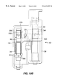
- FIG. 19A shows a front elevation of the circuit interrupter of FIG. 1 depicting the under voltage relay arrangement
- FIG. 19B shows an enlarged view of the under voltage release mechanism of FIG. 19A
- FIG. 19C shows an orthogonal view of the under voltage release mechanism of FIGS. 19A AND 19B;
- FIG. 20 shows an orthogonal view of the circuit interrupter similar to that shown in FIG. 1 but with interphase wire trough barriers in place;
- FIG. 21A shows a partially broken away orthogonal view of the circuit breaker of FIG. 1 from the back;
- FIG. 21B shows a partially broken away orthogonal view of the circuit breaker of FIG. 1 from the back so as to depict the DIN rail attachment region;
- FIG. 22A shows an orthogonal view of a load or line terminal collar embodied in the present invention.
- FIG. 22B shows an orthogonal view of the collar of FIG. 22A disposed upon a line conductor.
- Molded case circuit breaker 10 includes a lower base portion 14 mechanically interconnected with a primary cover 18 . Disposed on top of the primary cover 18 is an auxiliary or secondary cover 22 .
- the secondary cover 22 may include slightly depressed regions 22 A therein into which nameplates for the circuit breaker 10 may be disposed.
- the secondary cover 22 may be removed from the circuit breaker rendering some internal portions of the circuit breaker available for maintenance and the like without disassembling the entire circuit breaker.
- the secondary cover 22 may shield auxiliary devices such as under-voltage relays, bell alarms and auxiliary switches, for example, which will be described hereinafter.
- Holes or openings 26 are provided in the secondary cover 22 for accepting screws for fastening the auxiliary or secondary cover 22 to the primary cover 18 .
- Additional holes 30 which feed through the auxiliary cover 22 , the primary cover 18 and the base 14 are provided for bolting the entire circuit breaker assembly onto a wall, into a DIN rail back panel or into a load center or the like.
- the auxiliary cover 22 includes an auxiliary cover handle opening 34 .
- the primary or main cover 18 includes a primary cover handle opening 38 .
- There is provided a handle 42 which protrudes through the aforementioned auxiliary cover handle opening 34 and the primary cover handle opening 38 .
- the handle 42 is utilized in the normal manner to open and close the contacts of the circuit breaker manually and to reset the circuit breaker when it has been tripped. It may also be provided as an indication of the status of the circuit breaker, that is whether the circuit breaker is ON, OFF or TRIPPED.
- base 14 there is also shown in base 14 an elongated circular groove 22 C for capturing the combination push-to-trip interlock member in a manner which will be described more fully hereinafter.
- Protruding upwardly through the rectangular opening 22 B is a top portion 23 A of the aforementioned combination push-to-trip interlock member the details of which will be more fully explained hereinafter.
- three load conductor openings 46 which shield and protect load terminals 50 (not shown).
- the circuit breaker depicted is a three-phase circuit breaker. However, the invention is not limited to three-phase operation. Not depicted in FIGS. 1 and 2 are the LINE terminals which will be described hereinafter.
- member 23 includes a rectangular push-button top portion 23 A which was described with respect to FIG. 2 .
- extended circular guide member 23 B which is connected in interlocking disposition with the aforementioned groove 22 C such that member 23 may move upwardly or downwardly in the directions 23 H and 23 K, but may not rotate or move otherwise.
- a set of shoulders 23 E which separate the main body of the combination member 23 from its push-to-trip region 23 A.
- the shoulders 23 E abut upwardly against the bottom surface of the secondary cover 22 to prevent further linear motion in the upward direction.
- the middle bottom portion of the member 23 B is designated 23 F and it provides a seat for a compression spring (not shown) which biases the member 23 in the direction 23 H.
- a rotatable trip shaft 200 is shown which will be described in further detail hereinafter. For the purposes of this portion of the invention it is sufficient to say that the trip shaft 200 is biased rotationally by a torsion spring in the rotational direction opposite to that shown at 200 C.
- the combination member 23 provides the aforementioned rotation 200 C in either of two manners. If the push-to-trip surface 23 A is actuated downwardly in the direction, 23 K push-to-trip tab member 23 J will impinge upon tab member 200 B which is rigidly attached to the rotating shaft 200 in such a member as to rotate the shaft 200 in the direction 200 C and cause a tripping action of the circuit breaker.
- FIG. 3 a longitudinal section of a side elevation, partially broken away and partially in phantom of the circuit breaker 10 is depicted. In this depiction, certain key features of the circuit breaker are shown. It is to be understood that many of these features will also be described in greater detail hereinafter.
- a plasma arc acceleration chamber comprising a slot motor assembly 54 and an arc extinguisher assembly 58 .
- contact assembly 56 comprising a movable contact arm 58 supporting thereon a movable contact 62 and a stationary contact arm 68 supporting thereon a stationary contact 64 .
- An operating mechanism 63 is also depicted. The operating mechanism 63 will be described in further detail hereinafter.
- the operating mechanism 63 is similar to and operates similarly to that shown and described in U.S. Pat. No. 4,503,408 issued Mar. 5, 1985, to Mrenna et al, which patent is herein incorporated by reference.
- a trip mechanism 67 which in this non-limiting embodiment of the invention is an electromagnetic trip mechanism. It is to be understood that in other embodiments of the invention a thermal trip mechanism may be utilized or a combination of a thermal trip mechanism and an electro-magnetic trip mechanism may be utilized.
- the slot motor assembly 54 includes a separate upper slot motor assembly 54 A and a separate lower slot motor assembly 54 B.
- the upper slot motor assembly 54 A includes stacked side-by-side U-shaped upper slot motor assembly plates 74 which are composed of magnetic material.
- lower slot motor assembly plates 78 are disposed in the lower slot motor assembly 54 B.
- Lower assembly plates 78 are also composed of magnetic material.
- the arc chute assembly 58 includes an arc chute 80 having spaced apart generally parallel angularly off-set arc chute plates 84 and an upper arc runner 84 A. There is also provided a lower runner 88 which is not part of the arc chute 80 . There is also provided a line terminal 71 .
- FIG. 4 and FIG. 13 an orthogonal view of an internal portion of the circuit breaker 10 is shown.
- a crossbar assembly 100 which traverses the width of the circuit breaker and which is rotatably disposed on an internal portion of the base 14 (not shown).
- Movement of a lower toggle link 144 causes the crossbar 100 and the associated movable contact arms 58 to rotate into or out of a disposition which places movable contacts 62 into or out of a disposition of electrical continuity with fixed contacts 64 .
- Each movable contact arm 58 is rotatably disposed upon a pivot pin 104 which is disposed in the movable contact cam housing 102 .
- movable contact cam housing 102 for each movable contact arm 58 .
- a cam follower 110 Disposed in the movable contact cam housing is a cam follower 110 which is spring loaded by way of a spring 112 (see FIG. 13) in the upward direction against the movable cam 110 (see FIG. 13 ).
- the cam follower 110 is inserted into the cam follower opening 114 in the housing 102 in a longitudinal direction and then raised upwardly against the cam 110 .
- the spring 112 is interposed between the upside of the bottom of the housing 102 and the bottom of the cam follower 110 thus urging the cam follower 110 against the bottom surface or camming surface 106 of the contact arm 58 .
- the movable contact arm 58 is free to rotate within limits independently of the rotation of the crossbar assembly 100 .
- the movable contact arm 58 can rotate upwardly about the movable contact pivot pin 104 under the influence of high magnetic forces whereupon it is latched in that disposition by the action of the rear most surface or latching surface of the movable contact arm 58 and the cam follower 110 .
- the movable contact arm 58 rotates in unison with the rotation of the housing 102 as housing 102 is rotated clockwise or counter-clockwise by the action of the lower link pin 144 .
- FIG. 4 Also depicted in FIG. 4 is a portion of a self-contained auxiliary switch and alarm lock 320 which will be described in greater detail with reference to FIG. 5 .
- the operating mechanism 63 comprises a handle assembly 126 , a cradle assembly 130 , an upper toggle link 140 , an interlinked lower toggle link 144 , and an upper toggle link pivot pin 148 which interlinks the upper toggle link 140 with the cradle assembly 130 .
- the lower toggle link 144 is pivotally interconnected with the upper toggle link 140 by way of the intermediate toggle link pivot pin 156 .
- There is provided a cradle assembly pin 160 which is laterally disposed between parallel, spaced apart operating mechanism support members 161 . Cradle assembly 130 is free to rotate within limits about cradle assembly pivot pin 160 .
- a handle assembly roller 164 which is disposed in and supported by the handle assembly 126 in such a manner as to make mechanical contact with a portion of the cradle assembly 130 during certain operations of the circuit breakers as will be described hereinafter.
- a main stop bar 168 which is also laterally disposed between the operating support members 161 . Stop bar 168 abuts and stops or prevents further clockwise movement of the movable contact arm 58 during a circuit breaker opening operation.
- the line terminal 71 and associated lower slot motor assembly and fixed contact support member 246 is shown.
- the fixed contact arm 68 , the fixed contact 64 , the arc runner 88 and the lower slot motor assembly 54 B all comprise portions of the lower slot motor assembly and fixed contact support member 246 .
- the shunt trip 92 comprises: a shunt trip coil 92 A which is normally non-energized, a spring loaded plunger 92 B which is spring-loaded to the off or left disposition by the spring 92 C in a normal condition, a spring-loaded plunger 92 E which is spring-loaded towards the crossbar arrangement 100 and a microswitch 92 D.
- the microswitch 92 D may be interconnected to a control facility by way of electrical lines 320 C 1 and 320 C 2 .
- the coil 92 A is energized thus causing the plunger 92 B to move to the right against the force of the spring 92 C to cause the trip mechanism 66 to trip in a manner to be described hereinafter.
- the crossbar arrangement 100 rotates upwardly or in the clockwise direction to the right thus causing the spring loaded plunger 92 E to move upwardly thus opening the contacts of the switch 92 D to prevent energy from being supplied to the coil which may have a tendency to burn it out.
- the spring 92 C causes the plunger 92 B to move to the left as shown in FIG.
- the case for the shunt trip 92 is of the molded variety. It can be dropped into the previously described opening 18 X to thus be covered by the secondary cover 22 in a manner described previously.
- the drop-in case for the shunt trip 92 comprises two snap together sides 92 G and 92 J which may be joined together by way of flexible snap in hook arrangements 92 F in case portion 92 G which in turn interconnects within opening 92 H in case portion 92 J.
- the shunt trip arrangement 92 may be replaced by an under voltage module which will be described in greater detail with respect to FIGS. 19A, B and C.
- FIG. 5 and FIG. 3 an orthogonal view of the lower base 14 with the upper cover 18 (FIG. 5) removed and some of the internal portions of the circuit breaker apparatus 10 disposed in place is shown.
- the under voltage relay 92 and shunt trip device are shown disposed in place having part of their collective protective cover broken away.
- the load conductor openings 46 are shown on the right and the panel mounting holes 30 B in the base are shown to the left.
- the plasma arc acceleration chamber 52 comprising the slot motor assembly 54 on the right and the arc extinguisher 58 on the left.
- the upper slot motor assembly 54 A includes stacked or layered, upper slot motor assembly plates 74 sandwiched between a front plate 292 and rear plate 296 of the upper slot motor assembly housing 291 which in turn comprises a portion of the upper slot motor assembly 54 A. Shown to the left of the slot motor assembly 54 is the arc chute 80 assembly or arc extinguisher 58 .
- the arc chute 80 comprises spaced, generally parallel, angularly slanted arc chute plates 84 of which the upper arc runner 84 A is most prominently shown.
- FIG. 6 an elevation of that part of the circuit breaker 10 particularly associated with the operating mechanism 63 is depicted.
- the contacts 62 and 64 are shown in the disconnected or open disposition of the circuit breaker operating mechanism 63 .
- Stop bar 168 is shown in a disposition sufficient to prevent movable contact arm 58 from rotating significantly further upwardly in a clockwise direction.
- Cradle assembly pivot pin 160 supports cradle assembly 130 in such a manner that handle assembly roller 164 abuts against a back portion 165 of the cradle assembly 130 .
- roller pin 164 rolls against arcuate portions of region 165 for the purpose of moving or rotating the cradle assembly 130 about cradle assembly pivot pin 160 in a clockwise direction for the purpose of resetting the circuit breaker in a manner which will be described hereinafter.
- intermediate latch 176 is shown in its latched position abutting hard against the lower portion 139 of the latch region 131 of the cradle assembly latch cutout 135 .
- a pair of side-by-side aligned compression springs (not shown) such is shown in U.S. Pat. No.
- 4,503,408 is disposed in the operating mechanism 63 between the top portion of the handle assembly 126 and the knee or intermediate toggle link pivot point 156 .
- the tension in the aforementioned springs has a tendency to load portion 139 against the intermediate latch 176 .
- Latch 176 is prevented from unlatching the cradle assembly 130 because the other end thereof is fixed in place by the trip bar assembly 200 which is spring biased in the counter-clockwise direction against the intermediate latch 176 .
- This is the standard latch arrangement found in all dispositions of the circuit breaker except the unlatched disposition which will be described hereinafter.
- positive off-link 188 which is biased against rotation in the clockwise direction abuts against the circular portion of the crossbar 100 in such a manner that the fixedly attached positive off-link upper portion 189 is in a disposition of clearance away from the handle assembly cutout 137 so that movement in the clockwise rotational direction of the handle assembly 126 will be in such a manner that the cutout 137 misses or clears the aforementioned positive off-link upper portion 189 .
- FIG. 7 the arrangement of the operating mechanism 63 is shown for the circuit breaker in the CLOSED disposition.
- an electrical current may flow from load terminal 50 to line terminal 71 through the closed contacts 62 and 64 of the circuit breaker.
- the handle 42 has been rotated in a counter-clockwise direction to the left thus causing fixedly attached handle assembly 126 to rotate to the left or in a counter-clockwise direction thus causing the intermediate toggle link pivot point 156 to be influenced by the tension springs attached thereto (not shown) and to the top of the handle mechanism 126 to cause the upper and lower toggle links 140 and 144 respectively to assume the position shown in FIG. 7 .
- the handle 42 has been rotated to the right to a rotational position indicative of the contacts being OPEN.
- the handle position corresponds with a legend on the auxiliary cover 22 which clearly indicates the status of the circuit breaker contacts as being OPEN.
- the handle has been rotated to the left or counter-clockwise to a rotational disposition indicated by a legend on the auxiliary cover 22 of the contacts being CLOSED.
- the TRIPPED disposition of the operating mechanism 63 is depicted.
- the TRIP disposition is related to an automatic or magnetically induced disposition of the circuit breaker in which the circuit breaker automatically opens in response to electro-magnetic or other stimulus related to the magnitude of the current flowing between the line conductor 71 and the load conductor 50 .
- a solenoid assembly 97 is provided which is interposed electrically between the load conductor 50 and the movable contact arm 58 and is thus exposed to the full electrical current flowing through the electrical contacts 62 and 64 when they are closed.
- the solenoid 97 interacts by way of an electro-magnetically controlled plunger (not shown herein for purposes of simplicity of illustration) to induce the trip bar assembly solenoid armature interface 208 to move downwardly, in response to the electromagnetic action of the solenoid assembly 97 , in a clockwise direction about a trip bar assembly pivot 204 to cause the attached trip bar assembly intermediate latch interface 212 to rotate correspondingly away from the intermediate latch 176 thus freeing the cradle assembly 130 which had been held in place at the latch region 131 in the cradle assembly latch cutout 135 to be rotated counter-clockwise under the influence of the tension springs (not shown) interacting between the top of the handle mechanism 126 and the intermediate toggle link pivot pin 156 .
- an electro-magnetically controlled plunger not shown herein for purposes of simplicity of illustration
- the handle 42 is maintained in an intermediate disposition between its disposition in the CLOSED state as shown in FIG. 7 and the OPEN state as shown in FIG. 6 .
- This disposition between the full off and full on positions is depicted on the secondary cover 22 of the circuit breaker 10 as an indication that the circuit breaker is in the TRIPPED state. Once in this disposition the circuit breaker may not be turned on again until it is RESET as will be described hereinafter. After that the handle 42 may be rotated in the counter-clockwise direction to the ON state depicted in FIG. 7 for causing the contacts 62 and 64 to close once again and abut each other in the arrangement of the operating mechanism 63 depicted in FIG. 7 .
- FIG. 9 the disposition of the operating mechanism 63 during resetting operation is depicted. This occurs while the contacts 62 and 64 remain open and is exemplified by a forceful movement of the contact handle 42 to the right or in clockwise direction after a tripping operation has occurred as described with respect to FIG. 8 .
- the forceful movement of the arm 42 to the right or towards the OPEN indication on the secondary cover 22 (not shown) of the circuit breaker causes fixedly attached handle assembly 126 to move correspondingly.
- the handle assembly roller 164 makes contact with the back portion 165 of the cradle assembly 130 thus forcing it to rotate clockwise against the tension of the springs (not shown) located between the top of the handle mechanism 126 and the intermediate toggle link pivot point 156 until the upper portion 139 of the cradle assembly latch cut-out 135 abuts against the upper arm of the intermediate latch 176 forcing that intermediate latch to rotate to the left or counter-clockwise so that the bottom portion thereof, also rotates counter-clockwise to the right to a disposition of interlatching with the trip bar assembly intermediate latch interface 212 .
- the moveable contact arm 58 may independently pivot about its pivot 142 under the influence of extremely high current by way of well understood magnetic action causing the contacts 62 and 64 to separate in a period of time faster than can normally occur as the result of the action of the solenoid assembly 97 as was described previously. This operation will be further described with respect to FIGS. 3, 5 , 16 A and 16 B where the blow open arrangement of the circuit breaker is described in greater detail.
- FIG. 10 a portion of the operating mechanism 63 broken away from other portions of the circuit breaker 10 as well as portions of the movable and stationary contacts 62 and 64 and the associated supports therefore are shown.
- the contacts are shown in the closed state with moveable contact arm 58 causing movable contact 62 to abut against stationary contact 64 as disposed on stationary contact support arm 68 .
- a portion of the separation wall 69 between the operating mechanisms 63 and the arcing chamber to the left is shown.
- the separation wall 69 in addition to providing physical structure for the circuit breaker, also provides a barrier wall to assist in preventing hot gases from the arcing area on the left from escaping rightwardly towards the operating mechanism 63 on the right.
- the height of the separation wall 69 is limited by the need for the contact arm 58 to protrude from the region of the operating mechanism 63 to the region of the contact 64 .
- the contacts remain closed but the handle mechanism 126 has been pivotally rotated to the right as in a opening operation or a tripping operation. In this state an indication must be provided for indicating to an observer that the contacts have not opened, even though it may appear that an opening operation has occurred.
- cross bar 100 which has a cross bar positive operating protrusion 101 disposed thereon abuts against positive off-link 188 which is in turn rotated counter-clockwise thereby about its rotational axis 192 .
- the cam follower 110 comprises a main body 111 having on the rear thereof two oppositely disposed transversely protruding cam follower rear tabs 113 . Correspondingly in the front thereof there are two transversely protruding oppositely disposed cam follower front tabs 115 . On the top of the main body 111 is provided a cam follower top rear cam surface 121 and on the front thereof is provided a cam follower top front cam surface 121 A.
- the cam follower housing 102 disposed on the crossbar assembly 100 includes a cam follower opening 114 having on the inside thereof an inside wall and a pair of oppositely disposed parallel inside wall guides 117 disposed upwardly along the housing 102 . Disposed below the aforementioned guide walls 117 are oppositely disposed, parallel, longitudinally extended inside wall grooves 118 .
- the tabs 113 are aligned in the grooves 118 in the front of the housing 102 and then pushed inwardly towards the rear. This movement continues until the rearwardly protruding facing surfaces 115 A align with the front of the housing body 102 . At this point the rear tabs 113 have cleared the rear most portion of the groove 118 .
- cam follower 110 is raised so that the frontwardly facing surfaces 113 A and the rearwardly facing surfaces 115 A may slide respectively against the rearward and frontward facing walls formed transversely of the side walls 117 .
- spring 112 is disposed between the top of the bottom most portion of the housing 102 and the lower inner surface of the cam 110 against which it is seated. The pressure of the spring 112 maintains the tabular members 115 and 113 clear of the grooves 118 and against the front and rear portions of the walls 117 respectively, thus restraining movement of the cam follower 110 in the housing 102 to upward and downward.
- contact support arm 58 when a magnetic blow-open condition occurs as was described previously, contact support arm 58 immediately forcefully rotates about its pivot 104 in a clockwise direction thus bringing attached contact 62 with it, thus separating contacts 62 and 64 (not shown). The contact arm rotational motion is prevented from continuing in the clock-wise direction by the main stop bar 168 (not shown). Since the cross bar assembly 100 has not begun to react to the circuit breaker magnetic trip opening action it remains in place rotationally on its axis 105 .
- the rotation of the movable contact arm 58 causes the rearwardly extending movable contact cam surface 106 thereof to move away from the cam follower top rear surface 121 towards the cam follower top front cam surface 121 A whereupon it depresses the cam follower 110 against the spring 112 thus moving the cam follower down the walls 117 to a disposition where the front of the cam tends to close off a significant portion of the front of the cam follower housing opening 114 thus protecting the spring member 112 from hot gas 149 which is forcefully blown over the wall 69 towards the region of the cam follower 110 and spring 112 during current interruption.
- trip bar assembly 200 which includes as part thereof the trip bar assembly intermediate latch interface 212 protruding upwardly and the trip bar assembly solenoid armature interface 208 protruding to the right.
- Trip bar assembly 200 is disposed to rotate against a bias torsion spring (not shown) around trip bar assembly pivot 204 .
- the bias spring biases the trip bar assembly in the counter-clockwise direction.
- a solenoid coil 216 which is interconnected with load terminal 50 and by way of a braid or flexible conductor 51 with the rear most portion of the movable contact arm 58 .
- a solenoid armature guide 221 is in place for capturing therein and guiding therein in a direction longitudinal of the solenoid coil 216 a movable core 224 .
- the upper end of the movable core 224 is interconnected with a magnetic trip upper assembly 214 .
- the movable core 224 has disposed thereon a movable core plunger 231 .
- An upper interface seat 234 is provided.
- the multi-rate magnetic trip spring 220 is disposed around the movable core 224 between the fixed spring seat 239 on the top and the movable multi-rate magnetic trip spring seat 230 on the bottom. Adjustment of the cam 67 causes the movable spring seat 230 on the bottom to transpose axially, thus changing the air gap 246 without affecting the length of the spring 220 .
- the strength of the magnetic flux or magnetic force in the air gap 243 is a function of the amount of current flowing in the coil 216 and the size of the air gap 243 .
- This force has a tendency to draw the movable core 224 towards the stationary core 242 to reduce the size of the air gap 246 and is resisted by the multi-rate magnetic trip spring 220 .
- the plunger 230 causes the trip bar assembly solenoid armature interface 208 to move downwardly causing the trip bar assembly 200 to rotate about its pivot point 204 in a clock-wise direction against the force of its torsion spring.
- the spring 220 is formed with a multiple winding pitch with more windings per unit axial length at the bottom thereof and less windings per unit axial length at the top thereof.
- other winding arrangements may be used to accomplish the same purpose using different spring factors: continuous movable spring pitch, different spring wire diameters, different spring materials.
- the magnetic force induced in the solenoid coil by current flowing through the solenoid will cause the plunger 224 to move down slowly at first until all of the tightly wound spring pitch members have been compressed after which the coil will move more quickly as the more loosely wound spring coil pitch members are utilized to resist the movement of the core.
- This allows for a wider range of trip adjustment which may be, for example, from three times full rated current to eleven time full rated current.
- the exact adjustment of the tripping point is determined at least in part by the orientation of the cam member 67 .
- Member 246 has a lower slot motor assembly arc plate opening 250 into which the lower arc plates 78 are disposed in a side-by-side layered relationship. These magnetic members form the lower part of the completed circuit of the magnetic slot motor 54 as described previously.
- Element 254 is disposed on and forms part of the right most portion of the lower slot motor assembly and fixed contact support member 246 . It comprises a curvilinear member having a central opening or hollow recess 256 and a curved main contact support member surface 260 . There is also provided a main contact support upper region 264 .
- the aforementioned lower arc plate opening 250 and its surrounding housing member as well as the main contact support 254 and the main contact support upper region 264 are formed integrally of a single piece of material which may, for example, be molded material having high electrical insulating characteristics and strong structural characteristics.
- the main contact support upper region 264 has a lower concave surface 268 and main contact support upper region 286 .
- the main contact support upper region 286 also has a peninsula 272 extending therefrom upon which the movable contact arm 58 (not shown) rests in the close contact disposition thereof.
- Arc runner 88 is shown disposed along the upper surface 282 of the housing 246 . It is captured between a pair of upper contact support protrusions 280 which are integrally molded into the aforementioned housing 246 .
- the fixed contact arm 68 comprises a U-shaped member interconnected with the line terminal 71 on one end and the fixed contact 64 on the other end.
- the curved U-shaped member is disposed around the main contact support 254 so that the upper part of the U-shaped member is captured between outer surface 260 and concave surface 268 while the lower or other part of the U-shaped portion is disposed under the housing exemplified by the lower slot motor assembly 246 .
- the thusly captured support arm 68 bears downwardly against the upper surface 274 of the arc runner 88 and holds it in place against the upper part 282 of the housing 246 with the tabular members 280 preventing sideways motion of the arc runner 88 .
- the arcing contact 88 cannot move longitudinally because it has an end 274 A thereof which is offset at right angles to the main portion thereof and is trapped in a grooved formed by one side of the housing 246 and the inner side of the main contact support 254 .
- the upper slot motor assembly housing 291 is depicted. It comprises a rear plate 296 , a front plate 292 and an inner-support or mandrel 302 .
- the shape of the inner-support 302 is basically that of a U. Disposed on the U shaped inner-support 302 around the bite piece thereof and extending from one foot 298 to the other thereof are corresponding U-shaped layered magnetic plates 74 which correspond generally in a one-to-one relationship to the plates 78 shown in the opening 250 in the housing 246 of FIG. 15 . These plates are aligned in a layered manner from the front plate 292 to the rear plate 296 .
- assembly housing 291 When thusly assembled, assembly housing 291 is disposed on top of the lower slot motor assembly 246 , so that feet 298 are disposed on either side of the arc runner 88 as shown in FIG. 15 .
- the central opening formed thereby provides a slotted channel in which the movable arm 58 may reside and traverse during a contact opening or closing operation. Electrical current continues to flow in the movable contact arm 58 and through an electric arc between contacts 62 and 64 during a contact opening operation. This current induces a magnetic field into the closed magnetic loop provided by the combined upper and lower plates 74 and 78 respectively in the upper contact assembly 291 and lower contact assembly 246 respectively.
- This magnetic field interacts with the aforementioned current electromagnetically in such a way as to accelerate the movement of the opening contact arm 58 in such a manner as to more rapidly separate contacts 62 and 64 .
- the higher the electrical current flowing in the arc the higher the magnetic interaction and the more quickly the contacts 62 and 64 separate. For very high current this provides the aforementioned blow open operation associated with FIG. 13 .
- the material of the housing 291 may comprise a gas evolving material such as cellulose filled Melamine Formaldehyde which helps to move the arc toward the arc chute and it flattens it against the arc plates in the form of a band or ribbon. This shape makes it easier to split the arc and move it into the arc chute, thereby obtaining the high level of arc voltage required.
- FIGS. 3, 15 and 17 an attachment arrangement for the line conductor 71 and fixed contact support member 68 is depicted.
- a cut away portion of the base member 14 is shown in FIG. 17 .
- the stationary arm 68 with its characteristic U-shape is terminated in an offset load terminal 71 .
- a hole or opening 104 in the contact arm 68 fits over and around the post 308 .
- a line conductor retaining ring 310 is disposed on the fastening post 308 after the contact arm 68 has been placed thereon.
- the fixed contact arm 68 is securely fixed in and to the base 14 by way of the line conductor fastening post 308 and retaining ring 310 .
- the region 311 in the bite portion of the U-shaped member 68 is designated as the lower slot motor assembly region and it is in this region that the previously described lower slot motor assembly 246 is disposed as can be best seen by reference to FIGS. 3 and 15.
- FIGS. 5 and 18 the disposition of an auxiliary switch 320 and a bell alarm 324 is shown.
- an enclosure 326 shown partially broken away inside of which the auxiliary switch 320 is shown.
- a pair of auxiliary switches 320 or a pair of bell alarms 324 may be disposed within the enclosure 326 or the disposition of the auxiliary switch 320 and bell alarm 324 may be reversed.
- the bell alarm 324 is disposed in the same housing 326 on the other side of an insulating auxiliary wall 325 .
- Switch 320 has protruding from the bottom thereof an axially movable cam follower 328 which follows the upper cam surface 100 A of the cross bar assembly 100 .
- the assembly 100 is in one disposition and when the contacts 62 and 64 are open, the assembly is in a second disposition.
- the difference between the dispositions is tracked by the cam follower 328 .
- the cam follower 328 interconnects with contacts (not shown) in the auxiliary switch 320 such that normally open contact 320 A is in one disposition when the contacts 62 and 64 are open and in the opposite disposition when the contacts 62 and 64 are closed.
- the complimentary set of contacts 320 B are in the opposite dispositions at these times.
- Electrical wiring 320 C as shown in FIG. 5 may be interconnected with the terminals 321 and provided to a remote location.
- auxiliary switch 320 Appropriate power for causing certain desirable functions as a result of the status and/or change of status of the auxiliary switch 320 may be provided to a subset of these wires.
- a cradle follower 332 which protrudes at a right angle relative to the cam follower 328 from the other side of the enclosure 326 for interacting with or actuating the bell alarm 324 .
- the cradle follower 322 may cause the bell alarm 324 to be in a first electrical disposition or a second electrical disposition. This arrangement may be used to alert operating personnel that the contacts are either opened or closed.
- Both the auxiliary switch 320 and alarm 324 are contained within one enclosure 326 which is independently removable from the circuit breaker mechanism without complete disassembly thereof by removal of the aforementioned secondary or auxiliary cover 22 (not shown) and subsequent removal of the enclosure 326 . Insertion of the enclosure 326 may occur in a similar but reverse way.
- FIGS. 18A and 18B the detailed construction features of the enclosure 326 is depicted.
- portion of the switch arrangement 326 shown in its entirety in FIG. 18 .
- portion 326 A comprises an opening 332 A through which the bar 332 of FIG. 18 protrudes outwardly beyond the case 326 .
- one-half of the guiding arrangement 328 A for the plunger 328 of FIG. 18 is also shown.
- Two horizontal poles 450 and 452 are provided for matching up with complementary openings in the bell alarm or auxiliary switch of FIG. 18 for disposition of the bell alarm or auxiliary switch within the case 326 .
- sidewall 464 and sidewall 460 are also shown.
- the complimentary portion 326 B for portion 326 A is depicted.
- Slightly shorter poles 454 and 456 are provided for axially aligning with poles 452 and 450 respectively as the cover 326 B is joined to cover 326 A to form the completed switch enclosure 326 .
- the other half of the plunger mechanism guide 328 B is also shown protruding downwardly from casing 326 B.
- flexible snap devices 468 , 470 and 472 for snappingly engaging portions of the openings 474 , 468 and 478 respectively. Once this occurs, the two sides 328 A and 328 B joined.
- the sides 460 and 462 fit flush against each other and the sides 464 and 466 form an opening for access to the completed drop-in module 326 from above.
- the construction features for this device are similar to those used with respect to the shunt trip device 92 shown in FIG. 4 and the under voltage relay 93 shown in FIGS. 19A, B and C.
- the drop-in module 326 depicted in FIGS. 18, 18 A and 18 B drops into recess 18 Y in the primary cover 18 of FIG. 2 to subsequently be covered by the auxiliary or secondary cover 22 .
- FIGS. 5, 14 , 18 , 19 A, 19 B and 19 C the under voltage relay and shunt trip module 92 X is depicted for the circuit breaker 10 .
- Primary cover 14 has an opening therein through which the under voltage relay in 92 X is accessible.
- Handle 42 operates to reset the under voltage relay 92 X in the manner which will be described hereinafter with respect to FIG. 19 B.
- the trip bar assembly 100 has an extension which constitutes a trip bar assembly under voltage relay interface 212 . If interface 212 is contacted in such a manner as to rotate the trip bar in the counter-clockwise direction as shown in FIG. 14, the trip bar will cause the circuit breaker 10 to trip in a manner similar to that described with respect to FIG.
- circuit breaker mechanism can be tripped by either the action of the solenoid 216 , the under voltage relay 92 X, or the shunt trip mechanism 92 of FIG. 4 causing the trip bar to rotate in the counter-clockwise direction as viewed in FIG. 18 (clockwise in FIG. 14 ).
- under voltage relay 92 X has an enclosure case 92 XA in which the under voltage relay 92 X and its mechanism are disposed.
- an under voltage relay coil 338 which may be energized by electrical conductors connected to the under voltage relay terminals 92 B as shown best in FIG. 5 .
- an under voltage relay plunger arrangement 340 which is generally U-shaped having a lower section and an upper section. Plunger arrangement mechanism 340 has an opening 342 therein in which the right arm 352 A of the under voltage relay translating lever 352 is disposed.
- the under voltage relay translating lever 352 pivots above a fixed pivot 356 .
- the left arm 352 B thereof is disposed in an opening 360 A in the main plunger 360 of the under voltage relay 92 X.
- a fixed spring base or seat 369 There is also provided a screw section or threads 344 A upon which an adjustment nut arrangement 344 may be disposed. Alternatively, arrangement 344 may be replaced by a thumb screw.
- a spring 348 Interposed between the fixed spring seat 369 and the adjustable nut 344 is a spring 348 which surrounds the plunger 360 .
- the spring 348 forces the plunger 360 against left arm 352 B.
- the under voltage relay coil is normally on and normally holds the plunger 352 in a downward direction thus exerting force against the spring 348 .
- the coil 340 is de-energized as the coil voltage drops below a predetermined value, i.e. when an under voltage situation exists.
- the spring 348 acts against the plunger 360 causing it to move outwardly to strike the trip bar assembly under voltage relay interface 212 thus causing a trip operation as described previously.
- FIG. 20 an orthogonal view of circuit breaker 10 is shown.
- combination interface barriers and wiring troughs 374 are shown in place at the ends of the circuit breaker 10 .
- Barriers 374 are composed of insulating material and have hollow openings 375 through the longitudinal axes thereof into which electrical wiring such as auxiliary wiring 380 may be routed.
- Auxiliary wiring 380 may be provided to the external part of the circuit breaker 10 by way of opening 378 in the circuit breaker 10 .
- a similar opening 384 may be provided in the side of the circuit breaker 10 .
- auxiliary wiring is routed to the external part of the circuit breaker 10 from the opening 384 .
- the presence of the combination interface barrier and wiring trough 374 provides a solid insulating barrier between the incoming power leads which are interconnected with the load terminals 50 , for example.
- a DIN rail attachment 390 is shown.
- the circuit breaker 10 is shown in orthogonal view with the base 14 prominently displayed.
- the handle 42 is also shown for purposes of orientation.
- FIG. 21A the back plane 400 of the base 14 is depicted. In this state the circuit breaker 10 may be directly interconnected to a wall of a load center or panel board.
- FIG. 21B the DIN rail attachment 390 is shown attached to the back plane 400 .
- Device 390 may be securely fastened to the back plane 400 of the circuit breaker 10 by way of attachment devices 399 such as bolts.
- DIN rail mounting members 395 and 396 are provided for interaction with a typical DIN rail mounting arrangement.
- the plunger 398 may be activated to cause the movable latch 394 to clear the DIN rail during the mounting operation.
- the plunger 398 which is spring loaded springs back after the mounting procedure has begun causing the latch 394 to securely hold the circuit breaker 10 against the DIN rail (not shown) with the aid of members 395 and 396 .
- FIG. 22A a self-retaining collar for a load or line conductor is depicted.
- the collar is disposed, as shown in FIG. 22B, on the line conductor 71 .
- the collar 400 comprises a formed strip of rectangular cross-section, electrically conductive material such as copper folded over four times at 406 , 408 , 410 and 412 to form a hollow rectangular collar.
- One end, 414 of the rectangular member includes a portion of peninsular material 418 bent over at 416 which is fitted or dove-tailed into a fit with an opening 420 of similar shape in the side of the wall defined by the corners 406 to 408 .
- a rectangular protrusion 422 depends outwardly from the horizontal section of the bent over material emanating from fold over 406 towards the right.
- This latter rectangular portion is interlocked with a key member or opening 424 in the fold region 412 .
- This secure arrangement allows for a relatively strong collar member formed from a single unitary piece.
- a threaded opening 426 into which a threaded member may be axially disposed for downward movement into the central enclosure 428 of the collar member 400 for compressing wires or conductor which may be inserted therein.
- the embodiment of the invention as shown in FIG. 22A includes two side mounted protrusions or trapping members 430 A and 430 B which transversely protrude into the central opening 428 .
- the collar 400 is shown in a self-retained disposition on the line conductor 71 .
- the line conductor 71 fits between the lower portion 440 of the dowel-like protrusions 430 A and 430 B to trap the rectangular cross-section of the line conductor 71 therebetween and between the bottom 446 of the collar 400 .
- the protrusion 436 protrudes upwardly into the hole 71 A in the line terminal 71 thus longitudinally fixing the relationship between the collar 440 and the conductor 71 .
- the entrapping protrusions 430 A and 430 B prevent the vertical movement of the collar 440 relative to the conductor 71 as viewed in FIG. 22 B. Lateral movement is prevented by the location of the sidewalls shown, for example, at 450 and 452 in FIG. 22 B.
Landscapes
- Breakers (AREA)
Priority Applications (1)
| Application Number | Priority Date | Filing Date | Title |
|---|---|---|---|
| US09/504,602 US6232855B1 (en) | 1997-05-28 | 1998-03-30 | Circuit interrupter with covered accessory case, adjustable under voltage relay, self-retaining collar and one-piece rail attachment |
Applications Claiming Priority (2)
| Application Number | Priority Date | Filing Date | Title |
|---|---|---|---|
| US86410497A | 1997-05-28 | 1997-05-28 | |
| US09/504,602 US6232855B1 (en) | 1997-05-28 | 1998-03-30 | Circuit interrupter with covered accessory case, adjustable under voltage relay, self-retaining collar and one-piece rail attachment |
Related Parent Applications (1)
| Application Number | Title | Priority Date | Filing Date |
|---|---|---|---|
| US86410497A Division | 1997-05-28 | 1997-05-28 |
Publications (1)
| Publication Number | Publication Date |
|---|---|
| US6232855B1 true US6232855B1 (en) | 2001-05-15 |
Family
ID=25342541
Family Applications (2)
| Application Number | Title | Priority Date | Filing Date |
|---|---|---|---|
| US09/504,602 Expired - Fee Related US6232855B1 (en) | 1997-05-28 | 1998-03-30 | Circuit interrupter with covered accessory case, adjustable under voltage relay, self-retaining collar and one-piece rail attachment |
| US09/226,099 Expired - Fee Related US6052047A (en) | 1997-05-28 | 1998-03-30 | Circuit interrupter with covered accessory case, adjustable under voltage relay, self-retaining collar and one-piece rail attachment |
Family Applications After (1)
| Application Number | Title | Priority Date | Filing Date |
|---|---|---|---|
| US09/226,099 Expired - Fee Related US6052047A (en) | 1997-05-28 | 1998-03-30 | Circuit interrupter with covered accessory case, adjustable under voltage relay, self-retaining collar and one-piece rail attachment |
Country Status (7)
| Country | Link |
|---|---|
| US (2) | US6232855B1 (fr) |
| EP (1) | EP0887829A3 (fr) |
| AU (1) | AU753399B2 (fr) |
| CA (1) | CA2238901A1 (fr) |
| ID (1) | ID20341A (fr) |
| SG (1) | SG67511A1 (fr) |
| TW (1) | TW389923B (fr) |
Cited By (34)
| Publication number | Priority date | Publication date | Assignee | Title |
|---|---|---|---|---|
| US6469601B1 (en) * | 2001-04-27 | 2002-10-22 | Fuji Electric Co., Ltd. | Under-voltage tripping device with early-operation auxiliary switch for circuit breaker |
| US6924446B1 (en) | 2004-10-01 | 2005-08-02 | Eaton Corporation | Circuit breaker including a latchable cradle and a cross bar adapted to move in an arcuate path away from primary and secondary latches |
| US7012493B1 (en) | 2004-10-01 | 2006-03-14 | Eaton Corporation | Circuit breaker including rotary interlock for secondary cover |
| US7023303B1 (en) | 2004-10-01 | 2006-04-04 | Eaton Corporation | Actuator for auxiliary switch and circuit breaker incorporating the same |
| US20060071740A1 (en) * | 2004-10-01 | 2006-04-06 | Eaton Corporation | Undervoltage release and circuit breaker incorporating same |
| US20060071750A1 (en) * | 2004-10-01 | 2006-04-06 | Marks Douglas C | Support structure for a circuit interrupter latch and circuit breaker employing the same |
| US20060071745A1 (en) * | 2004-10-01 | 2006-04-06 | Stay Amelia M | Lockable fastener and circuit breaker employing the same |
| US20070080766A1 (en) * | 2005-10-06 | 2007-04-12 | Eaton Corporation | Shock-resistant under-voltage release |
| US20070171011A1 (en) * | 2006-01-23 | 2007-07-26 | Eaton Corporation | Auxiliary switch sub-assembly and electrical switching apparatus employing the same |
| US20070171010A1 (en) * | 2006-01-23 | 2007-07-26 | Eaton Corporation | Electrical switching apparatus and terminal housing therefor |
| US20080061912A1 (en) * | 2006-09-08 | 2008-03-13 | Siemens Aktiengesellschaft | Semiconductor switching module optimized for resistance to short circuits |
| US7385153B1 (en) | 2007-03-28 | 2008-06-10 | Eaton Corporation | Electrical switching apparatus and trip bar therefor |
| US20080157904A1 (en) * | 2006-12-29 | 2008-07-03 | General Electric Company | Activation for switching apparatus |
| US20080237193A1 (en) * | 2007-03-28 | 2008-10-02 | Bogdon Erik R | Electrical switching apparatus, and accessory module and electrical conductor mount therefor |
| US20080237192A1 (en) * | 2007-03-28 | 2008-10-02 | Whitaker Thomas A | Electrical switching apparatus and accessory tray therefor |
| US20080246564A1 (en) * | 2007-04-09 | 2008-10-09 | Whitaker Thomas A | Electrical switching apparatus accessory sub-assembly employing reversible coil frame, and accessory and electrical switching apparatus employing the same |
| US20080246569A1 (en) * | 2007-04-09 | 2008-10-09 | Bogdon Erik R | Electromagnetic coil apparatus employing a magnetic flux enhancer, and accessory and electrical switching apparatus employing the same |
| US20090301850A1 (en) * | 2008-06-09 | 2009-12-10 | Puhalla Craig J | Electrical switching apparatus and push-to-trip assembly therefor |
| US7800468B2 (en) | 2007-03-28 | 2010-09-21 | Eaton Corporation | Electrical switching apparatus, and accessory module and strain relief mechanism therefor |
| US7829808B2 (en) | 2007-03-28 | 2010-11-09 | Eaton Corporation | Electrical switching apparatus and accessory assembly therefor |
| US7868262B2 (en) | 2007-03-28 | 2011-01-11 | Eaton Corporation | Electrical switching apparatus, and sub-assembly and auxiliary switch tray therefor |
| US20110067988A1 (en) * | 2009-09-18 | 2011-03-24 | Leviton Manufacturing Co., Inc. | Electrical switching component |
| US20110090667A1 (en) * | 2009-10-15 | 2011-04-21 | Leviton Manufacturing Co., Inc. | Electrical component enclosure |
| US20110115448A1 (en) * | 2009-11-13 | 2011-05-19 | Leviton Manufacturing Co., Inc. | Electrical switching module |
| US20110118890A1 (en) * | 2009-11-13 | 2011-05-19 | Leviton Manufacturing Co., Inc. | Intelligent metering demand response |
| US20110115460A1 (en) * | 2009-11-13 | 2011-05-19 | Leviton Manufacturing Co., Inc. | Electrical switching module |
| US8664886B2 (en) | 2011-12-22 | 2014-03-04 | Leviton Manufacturing Company, Inc. | Timer-based switching circuit synchronization in an electrical dimmer |
| US20140126158A1 (en) * | 2012-11-02 | 2014-05-08 | Michael Baran | Modular overload relay assembly with mechanically isolated connector |
| US8736193B2 (en) | 2011-12-22 | 2014-05-27 | Leviton Manufacturing Company, Inc. | Threshold-based zero-crossing detection in an electrical dimmer |
| US20140202990A1 (en) * | 2013-01-24 | 2014-07-24 | Eaton Corporation | Arc runners suitable for dc molded case circuit breakers and related methods |
| EP3051569A1 (fr) * | 2015-01-22 | 2016-08-03 | LSIS Co., Ltd. | Structure de traverse de démarreur de moteur manuel |
| US9681526B2 (en) | 2014-06-11 | 2017-06-13 | Leviton Manufacturing Co., Inc. | Power efficient line synchronized dimmer |
| CN107026060A (zh) * | 2016-01-29 | 2017-08-08 | 俊朗电气有限公司 | 一种预防短路后误操作的断路器 |
| US10483068B1 (en) | 2018-12-11 | 2019-11-19 | Eaton Intelligent Power Limited | Switch disconnector systems suitable for molded case circuit breakers and related methods |
Families Citing this family (17)
| Publication number | Priority date | Publication date | Assignee | Title |
|---|---|---|---|---|
| US6255926B1 (en) * | 1999-08-30 | 2001-07-03 | Eaton Corporation | Circuit interrupter with accessory trip interface and break-away access thereto |
| US6472965B2 (en) * | 1999-11-05 | 2002-10-29 | Siemens Energy & Automation, Inc. | Molded case circuit breaker accessory system |
| US6201460B1 (en) * | 2000-02-18 | 2001-03-13 | Siemens Energy & Automation, Inc. | Undervoltage release device for a molded case circuit breaker |
| AU2003224289A1 (en) * | 2002-04-24 | 2003-11-10 | Stephen Capon | Consumer unit |
| US7403373B2 (en) * | 2006-01-10 | 2008-07-22 | Siemens Energy & Automation, Inc. | System and method for mounting a breaker |
| US7532097B2 (en) * | 2007-02-12 | 2009-05-12 | Eaton Corporation | Slot motor housing and circuit interrupter including the same |
| FR2999791B1 (fr) * | 2012-12-18 | 2015-01-02 | Schneider Electric Ind Sas | Dispositif modulaire de commutation electrique comportant au moins un bloc de coupure unipolaire et ensemble de commutation comportant de tels dispositifs |
| US9524842B2 (en) | 2014-12-19 | 2016-12-20 | Eaton Corporation | Molded case circuit breakers with a switch PCB over an internal pocket and behind a front cover |
| USD781244S1 (en) | 2015-02-18 | 2017-03-14 | Eaton Corporation | Front panel of a circuit breaker |
| DE102015203497A1 (de) * | 2015-02-26 | 2016-09-15 | Power Plus Communications Ag | Gehäuse für eine Elektrobaugruppe zur Montage auf einer Trageschiene sowie Kommunikationseinheit |
| EP3291276B1 (fr) * | 2015-04-28 | 2020-11-18 | Seari Electric Technology Co., Ltd. | Mécanisme de verrouillage secondaire pour mécanisme de fonctionnement de coupe-circuit |
| US9773624B2 (en) * | 2015-07-28 | 2017-09-26 | Eaton Corporation | Electrical switching apparatus and housing assembly therefor |
| US9653237B1 (en) * | 2015-12-03 | 2017-05-16 | Eaton Corporation | Electrical switching apparatus and slot motor therefor |
| US10665411B2 (en) * | 2017-09-28 | 2020-05-26 | Siemens Industry, Inc. | In multi-pole electronic circuit breakers preventing breaker armature from latching with cradle if certain criteria are met |
| CN108695751B (zh) * | 2018-06-26 | 2023-11-10 | 宁夏力成电气集团有限公司 | 固体绝缘柜模块化操动机构 |
| CN111755299B (zh) * | 2019-03-29 | 2022-07-05 | Ls产电株式会社 | 配线用断路器的灭弧装置 |
| CN111952124B (zh) * | 2020-07-31 | 2023-06-02 | 晨诺电气科技集团有限公司 | 一种高压输电用的高温断电器 |
Citations (4)
| Publication number | Priority date | Publication date | Assignee | Title |
|---|---|---|---|---|
| US3293577A (en) * | 1965-09-21 | 1966-12-20 | Gen Electric | Undervoltage release for circuit breaker |
| US5093643A (en) * | 1990-10-22 | 1992-03-03 | Westinghouse Electric Corp. | Undervoltage release device assembly for circuit breaker |
| US5347248A (en) * | 1991-02-19 | 1994-09-13 | Heinrich Kopp Ag | Protective switching device for difference-current and undervoltage tripping |
| US5886605A (en) * | 1998-05-07 | 1999-03-23 | Eaton Corporation | Actuator assembly with calibration means and electrical power switch apparatus incorporating the actuator assembly with calibration means |
Family Cites Families (5)
| Publication number | Priority date | Publication date | Assignee | Title |
|---|---|---|---|---|
| US4912439A (en) * | 1989-01-27 | 1990-03-27 | General Electric Company | Molded case circuit breaker auxiliary switch unit |
| US4982173A (en) * | 1990-03-01 | 1991-01-01 | General Electric Company | Rotatable trip test assembly for molded case circuit breakers |
| KR940007922A (ko) * | 1992-09-28 | 1994-04-28 | 기타오카 다카시 | 회로차단기 |
| US5761026A (en) * | 1996-04-02 | 1998-06-02 | Square D Company | Snap-on circuit breaker mounting system |
| US5768091A (en) * | 1996-11-21 | 1998-06-16 | Lennox Manufacturing Inc. | Circuit breaker mounting bracket |
-
1998
- 1998-03-30 US US09/504,602 patent/US6232855B1/en not_active Expired - Fee Related
- 1998-03-30 US US09/226,099 patent/US6052047A/en not_active Expired - Fee Related
- 1998-05-11 TW TW087107208A patent/TW389923B/zh active
- 1998-05-12 SG SG1998001344A patent/SG67511A1/en unknown
- 1998-05-14 EP EP98108829A patent/EP0887829A3/fr not_active Withdrawn
- 1998-05-22 AU AU68049/98A patent/AU753399B2/en not_active Ceased
- 1998-05-26 CA CA002238901A patent/CA2238901A1/fr not_active Abandoned
- 1998-05-28 ID IDP980786A patent/ID20341A/id unknown
Patent Citations (4)
| Publication number | Priority date | Publication date | Assignee | Title |
|---|---|---|---|---|
| US3293577A (en) * | 1965-09-21 | 1966-12-20 | Gen Electric | Undervoltage release for circuit breaker |
| US5093643A (en) * | 1990-10-22 | 1992-03-03 | Westinghouse Electric Corp. | Undervoltage release device assembly for circuit breaker |
| US5347248A (en) * | 1991-02-19 | 1994-09-13 | Heinrich Kopp Ag | Protective switching device for difference-current and undervoltage tripping |
| US5886605A (en) * | 1998-05-07 | 1999-03-23 | Eaton Corporation | Actuator assembly with calibration means and electrical power switch apparatus incorporating the actuator assembly with calibration means |
Cited By (64)
| Publication number | Priority date | Publication date | Assignee | Title |
|---|---|---|---|---|
| US6469601B1 (en) * | 2001-04-27 | 2002-10-22 | Fuji Electric Co., Ltd. | Under-voltage tripping device with early-operation auxiliary switch for circuit breaker |
| US7369021B2 (en) | 2004-10-01 | 2008-05-06 | Eaton Corporation | Undervoltage release and circuit breaker incorporating same |
| US6924446B1 (en) | 2004-10-01 | 2005-08-02 | Eaton Corporation | Circuit breaker including a latchable cradle and a cross bar adapted to move in an arcuate path away from primary and secondary latches |
| US7012493B1 (en) | 2004-10-01 | 2006-03-14 | Eaton Corporation | Circuit breaker including rotary interlock for secondary cover |
| US7023303B1 (en) | 2004-10-01 | 2006-04-04 | Eaton Corporation | Actuator for auxiliary switch and circuit breaker incorporating the same |
| US20060071740A1 (en) * | 2004-10-01 | 2006-04-06 | Eaton Corporation | Undervoltage release and circuit breaker incorporating same |
| US20060071750A1 (en) * | 2004-10-01 | 2006-04-06 | Marks Douglas C | Support structure for a circuit interrupter latch and circuit breaker employing the same |
| US20060071744A1 (en) * | 2004-10-01 | 2006-04-06 | Eaton Corporation | Actuator for auxiliary switch and circuit breaker incorporating the same |
| US20060071745A1 (en) * | 2004-10-01 | 2006-04-06 | Stay Amelia M | Lockable fastener and circuit breaker employing the same |
| US20060071743A1 (en) * | 2004-10-01 | 2006-04-06 | Marks Douglas C | Circuit breaker including rotary interlock for secondary cover |
| US7145420B2 (en) | 2004-10-01 | 2006-12-05 | Cleveland, Ohio | Support structure for a circuit interrupter latch and circuit breaker employing the same |
| US7218192B2 (en) | 2004-10-01 | 2007-05-15 | Eaton Corporation | Lockable fastener and circuit breaker employing the same |
| US20070080766A1 (en) * | 2005-10-06 | 2007-04-12 | Eaton Corporation | Shock-resistant under-voltage release |
| US7486164B2 (en) | 2005-10-06 | 2009-02-03 | Eaton Corporation | Shock-resistant under-voltage release |
| US20070171010A1 (en) * | 2006-01-23 | 2007-07-26 | Eaton Corporation | Electrical switching apparatus and terminal housing therefor |
| US7319373B2 (en) * | 2006-01-23 | 2008-01-15 | Eaton Corporation | Electrical switching apparatus and terminal housing therefor |
| US20070171011A1 (en) * | 2006-01-23 | 2007-07-26 | Eaton Corporation | Auxiliary switch sub-assembly and electrical switching apparatus employing the same |
| US7369022B2 (en) * | 2006-01-23 | 2008-05-06 | Eaton Corporation | Auxiliary switch sub-assembly and electrical switching apparatus employing the same |
| US20080061912A1 (en) * | 2006-09-08 | 2008-03-13 | Siemens Aktiengesellschaft | Semiconductor switching module optimized for resistance to short circuits |
| US7864004B2 (en) * | 2006-12-29 | 2011-01-04 | General Electric Company | Activation for switching apparatus |
| US20080157904A1 (en) * | 2006-12-29 | 2008-07-03 | General Electric Company | Activation for switching apparatus |
| US7829808B2 (en) | 2007-03-28 | 2010-11-09 | Eaton Corporation | Electrical switching apparatus and accessory assembly therefor |
| US7645953B2 (en) | 2007-03-28 | 2010-01-12 | Eaton Corporation | Electrical switching apparatus, and accessory module and electrical conductor mount therefor |
| US7868262B2 (en) | 2007-03-28 | 2011-01-11 | Eaton Corporation | Electrical switching apparatus, and sub-assembly and auxiliary switch tray therefor |
| US20080237192A1 (en) * | 2007-03-28 | 2008-10-02 | Whitaker Thomas A | Electrical switching apparatus and accessory tray therefor |
| US7385153B1 (en) | 2007-03-28 | 2008-06-10 | Eaton Corporation | Electrical switching apparatus and trip bar therefor |
| US20080237193A1 (en) * | 2007-03-28 | 2008-10-02 | Bogdon Erik R | Electrical switching apparatus, and accessory module and electrical conductor mount therefor |
| US7598834B2 (en) | 2007-03-28 | 2009-10-06 | Eaton Corporation | Electrical switching apparatus and accessory tray therefor |
| US7800468B2 (en) | 2007-03-28 | 2010-09-21 | Eaton Corporation | Electrical switching apparatus, and accessory module and strain relief mechanism therefor |
| US7557681B2 (en) * | 2007-04-09 | 2009-07-07 | Eaton Corporation | Electrical switching apparatus accessory sub-assembly employing reversible coil frame, and accessory and electrical switching apparatus employing the same |
| US7598830B2 (en) * | 2007-04-09 | 2009-10-06 | Eaton Corporation | Electromagnetic coil apparatus employing a magnetic flux enhancer, and accessory and electrical switching apparatus employing the same |
| US20080246564A1 (en) * | 2007-04-09 | 2008-10-09 | Whitaker Thomas A | Electrical switching apparatus accessory sub-assembly employing reversible coil frame, and accessory and electrical switching apparatus employing the same |
| US20080246569A1 (en) * | 2007-04-09 | 2008-10-09 | Bogdon Erik R | Electromagnetic coil apparatus employing a magnetic flux enhancer, and accessory and electrical switching apparatus employing the same |
| US20090301850A1 (en) * | 2008-06-09 | 2009-12-10 | Puhalla Craig J | Electrical switching apparatus and push-to-trip assembly therefor |
| US7910850B2 (en) * | 2008-06-09 | 2011-03-22 | Eaton Corporation | Electrical switching apparatus and push-to-trip assembly therefor |
| AU2009202382B2 (en) * | 2008-06-09 | 2013-05-30 | Eaton Corporation | Electrical switching apparatus and push-to-trip assembly therefor |
| US8330062B2 (en) | 2009-09-18 | 2012-12-11 | Leviton Manufacturing Co., Inc. | Electrical switching component |
| US8558129B2 (en) | 2009-09-18 | 2013-10-15 | Leviton Manufacturing Co., Inc. | Electrical switching component |
| US20110067988A1 (en) * | 2009-09-18 | 2011-03-24 | Leviton Manufacturing Co., Inc. | Electrical switching component |
| US20110090667A1 (en) * | 2009-10-15 | 2011-04-21 | Leviton Manufacturing Co., Inc. | Electrical component enclosure |
| US8281951B2 (en) | 2009-10-15 | 2012-10-09 | Leviton Manufacturing Co., Inc. | Electrical component enclosure |
| US8755944B2 (en) | 2009-11-13 | 2014-06-17 | Leviton Manufacturing Co., Inc. | Electrical switching module |
| US8324761B2 (en) | 2009-11-13 | 2012-12-04 | Leviton Manufacturing Co., Inc. | Electrical switching module |
| US20110115460A1 (en) * | 2009-11-13 | 2011-05-19 | Leviton Manufacturing Co., Inc. | Electrical switching module |
| US8463453B2 (en) | 2009-11-13 | 2013-06-11 | Leviton Manufacturing Co., Inc. | Intelligent metering demand response |
| US20110118890A1 (en) * | 2009-11-13 | 2011-05-19 | Leviton Manufacturing Co., Inc. | Intelligent metering demand response |
| US20110115448A1 (en) * | 2009-11-13 | 2011-05-19 | Leviton Manufacturing Co., Inc. | Electrical switching module |
| US8880232B2 (en) | 2009-11-13 | 2014-11-04 | Leviton Manufacturing Co., Inc. | Intelligent metering demand response |
| US8664886B2 (en) | 2011-12-22 | 2014-03-04 | Leviton Manufacturing Company, Inc. | Timer-based switching circuit synchronization in an electrical dimmer |
| US8736193B2 (en) | 2011-12-22 | 2014-05-27 | Leviton Manufacturing Company, Inc. | Threshold-based zero-crossing detection in an electrical dimmer |
| US20140126158A1 (en) * | 2012-11-02 | 2014-05-08 | Michael Baran | Modular overload relay assembly with mechanically isolated connector |
| US9230765B2 (en) * | 2012-11-02 | 2016-01-05 | Rockwell Automation Technologies, Inc. | Modular overload relay assembly with mechanically isolated connector |
| US9029727B2 (en) * | 2013-01-24 | 2015-05-12 | Eaton Corporation | Arc runners suitable for DC molded case circuit breakers and related methods |
| CN104885176A (zh) * | 2013-01-24 | 2015-09-02 | 伊顿公司 | 适用于dc模制外壳断路器的电弧滑槽及其相关方法 |
| US20140202990A1 (en) * | 2013-01-24 | 2014-07-24 | Eaton Corporation | Arc runners suitable for dc molded case circuit breakers and related methods |
| CN104885176B (zh) * | 2013-01-24 | 2017-11-17 | 伊顿公司 | 适用于dc模制外壳断路器的电弧滑槽及其相关方法 |
| US9681526B2 (en) | 2014-06-11 | 2017-06-13 | Leviton Manufacturing Co., Inc. | Power efficient line synchronized dimmer |
| US9974152B2 (en) | 2014-06-11 | 2018-05-15 | Leviton Manufacturing Co., Inc. | Power efficient line synchronized dimmer |
| EP3051569A1 (fr) * | 2015-01-22 | 2016-08-03 | LSIS Co., Ltd. | Structure de traverse de démarreur de moteur manuel |
| CN105826137A (zh) * | 2015-01-22 | 2016-08-03 | Ls产电株式会社 | 用于手动电动机起动器的闩件结构 |
| US9734959B2 (en) | 2015-01-22 | 2017-08-15 | Lsis Co., Ltd. | Structure of crossbar for manual motor starter |
| CN105826137B (zh) * | 2015-01-22 | 2018-03-16 | Ls产电株式会社 | 用于手动电动机起动器的闩件结构 |
| CN107026060A (zh) * | 2016-01-29 | 2017-08-08 | 俊朗电气有限公司 | 一种预防短路后误操作的断路器 |
| US10483068B1 (en) | 2018-12-11 | 2019-11-19 | Eaton Intelligent Power Limited | Switch disconnector systems suitable for molded case circuit breakers and related methods |
Also Published As
| Publication number | Publication date |
|---|---|
| US6052047A (en) | 2000-04-18 |
| EP0887829A2 (fr) | 1998-12-30 |
| TW389923B (en) | 2000-05-11 |
| CA2238901A1 (fr) | 1998-11-28 |
| AU753399B2 (en) | 2002-10-17 |
| ID20341A (id) | 1998-12-03 |
| SG67511A1 (en) | 1999-09-21 |
| EP0887829A3 (fr) | 2000-03-08 |
| AU6804998A (en) | 1998-12-03 |
Similar Documents
| Publication | Publication Date | Title |
|---|---|---|
| US6232855B1 (en) | Circuit interrupter with covered accessory case, adjustable under voltage relay, self-retaining collar and one-piece rail attachment | |
| EP0887831B1 (fr) | Disjoncteur verrouillé quand les contacts sont soudés, avec cavalier de came étanche aux gases et un ressort à double caractéristique élastique | |
| EP0887832B1 (fr) | Disjoncteur avec chambre d'acclereration de l'arc et logement pour bras de contact | |
| US6480082B1 (en) | Circuit breaker | |
| EP0176869B1 (fr) | Disjoncteur à boîtier moulé avec un moyen d'échappement pour le gaz d'arc | |
| KR920006061B1 (ko) | 회로차단기의 솔레노이드 가동형 작동기구 | |
| JPH04229920A (ja) | 回路遮断器の操作用ハンドル制限装置 | |
| US6281459B1 (en) | Circuit interrupter having an improved slot motor assembly | |
| AU646162B2 (en) | Circuit breaker with interlock for welded contacts | |
| EP0563368A1 (fr) | Disjoncteur de limitation du courant. | |
| WO1993008585A1 (fr) | Disjoncteur de limitation de courant avec aimant surmoule et plaques metalliques | |
| US5172088A (en) | Molded case circuit breaker combined accessory actuator-reset lever | |
| NZ235609A (en) | Circuit breaker includes spacer to reduce overcurrent response time. | |
| US4950848A (en) | Adjustable circuit breaker with draw out interlock | |
| EP0276074A2 (fr) | Disjoncteur à circuit magnétique shunt de rappel | |
| EP1077458B1 (fr) | Disjoncteur avec une borne asymétrique en forme de collier | |
| EP0692806B1 (fr) | Disjoncteur | |
| CA1325657C (fr) | Dispositif d'enclenchement de disjoncteur | |
| EP1643524B1 (fr) | Disjoncteur avec système de verrouillage rotatif pour deuxieme couvercle | |
| JPH0828178B2 (ja) | 回路遮断器 | |
| KR200498754Y1 (ko) | 배선용 차단기의 가조정 트립 장치 | |
| US5122771A (en) | Molded case circuit breaker combined accessory actuator-reset lever | |
| WO2025215677A1 (fr) | Agencement d'actionnement de déclenchement pour un ensemble actionneur d'un disjoncteur à boîtier moulé | |
| MXPA98004214A (en) | Circuit switch with aras plasma acceleration chamber and conta arm housing | |
| JPH04296420A (ja) | 回路遮断器 |
Legal Events
| Date | Code | Title | Description |
|---|---|---|---|
| FEPP | Fee payment procedure |
Free format text: PAYOR NUMBER ASSIGNED (ORIGINAL EVENT CODE: ASPN); ENTITY STATUS OF PATENT OWNER: LARGE ENTITY |
|
| FPAY | Fee payment |
Year of fee payment: 4 |
|
| FPAY | Fee payment |
Year of fee payment: 8 |
|
| REMI | Maintenance fee reminder mailed | ||
| LAPS | Lapse for failure to pay maintenance fees | ||
| STCH | Information on status: patent discontinuation |
Free format text: PATENT EXPIRED DUE TO NONPAYMENT OF MAINTENANCE FEES UNDER 37 CFR 1.362 |
|
| FP | Lapsed due to failure to pay maintenance fee |
Effective date: 20130515 |