US6232873B1 - Method and apparatus for signalling theft for a motor vehicle - Google Patents
Method and apparatus for signalling theft for a motor vehicle Download PDFInfo
- Publication number
- US6232873B1 US6232873B1 US08/960,202 US96020297A US6232873B1 US 6232873 B1 US6232873 B1 US 6232873B1 US 96020297 A US96020297 A US 96020297A US 6232873 B1 US6232873 B1 US 6232873B1
- Authority
- US
- United States
- Prior art keywords
- theft
- vehicle
- signalling
- sensor system
- indicative
- Prior art date
- Legal status (The legal status is an assumption and is not a legal conclusion. Google has not performed a legal analysis and makes no representation as to the accuracy of the status listed.)
- Expired - Fee Related
Links
Images


Classifications
-
- B—PERFORMING OPERATIONS; TRANSPORTING
- B60—VEHICLES IN GENERAL
- B60R—VEHICLES, VEHICLE FITTINGS, OR VEHICLE PARTS, NOT OTHERWISE PROVIDED FOR
- B60R25/00—Fittings or systems for preventing or indicating unauthorised use or theft of vehicles
- B60R25/01—Fittings or systems for preventing or indicating unauthorised use or theft of vehicles operating on vehicle systems or fittings, e.g. on doors, seats or windscreens
- B60R25/04—Fittings or systems for preventing or indicating unauthorised use or theft of vehicles operating on vehicle systems or fittings, e.g. on doors, seats or windscreens operating on the propulsion system, e.g. engine or drive motor
-
- B—PERFORMING OPERATIONS; TRANSPORTING
- B60—VEHICLES IN GENERAL
- B60R—VEHICLES, VEHICLE FITTINGS, OR VEHICLE PARTS, NOT OTHERWISE PROVIDED FOR
- B60R25/00—Fittings or systems for preventing or indicating unauthorised use or theft of vehicles
- B60R25/10—Fittings or systems for preventing or indicating unauthorised use or theft of vehicles actuating a signalling device
Definitions
- the invention relates to a method and apparatus for signalling theft for a motor vehicle, in which an item of theft-signalling information is produced as a function of the signal state of at least one of a plurality of signals which are output by corresponding vehicle-state monitoring means.
- vehicle-state monitoring means refers to the components on the vehicle which output signals that supply information on the current state of the vehicle. These include in particular sensors for detecting unauthorized tampering with an unauthorized access protection device (for example a central locking system), and/or an unauthorized use protection device (for example an electronic immobilizer), and vehicle components which produce signals relating to the operation of the vehicle, such as an ignition line signal, a fuel pump signal, signals from wheel rpm sensors etc.
- an unauthorized access protection device for example a central locking system
- an unauthorized use protection device for example an electronic immobilizer
- the theft-signalling information produced when an attempted theft is detected usually triggers an alarm system arranged on the vehicle.
- the theft-signalling information is transmitted (preferably in addition to triggering an alarm signal on the vehicle) via a wireless signal transmission link to a monitoring point outside the vehicle, in order to initiate suitable measures against the attempted theft from said point. For example, an electronic immobilizer and/or pursuit of a vehicle by means of an appropriate locating system, may be triggered.
- the theft-signalling information is produced if the signals which are indicative of vehicle states indicate an attempted theft, for example an attempt at break-in, an attempt at driving away or an attempt at transporting away.
- the theft-signalling information triggers the vehicle alarm, and is simultaneously passed on via the wireless transmission link to the remote monitoring point.
- the malfunction of one of the vehicle-state monitoring means which leads to incorrect production of the theft-detecting signal state for the respective signal, thus undesirably results in the monitoring point incorrectly concluding that a theft is occurring and initiating the appropriate countermeasures. There is therefore need for improvement of the reliability of the theft-detection means.
- the object of the present invention is to provide a method and apparatus of the type mentioned above, which makes it possible to signal thefts in a way which is comparatively protected against incorrect alarms, in particular, when necessary, also for signalling theft to a monitoring point which is arranged spatially remote from the vehicle.
- each such theft-signalling combination comprises one or more signalling conditions, which succeed one another in a specific time sequence and which themselves comprise one or more combinations, which are indicative of theft, of jointly interrogated signal states of the signals which are indicative of vehicle states.
- a theft is signalled only when the appropriate signal states of a plurality of signals which are indicative of theft occur in a correct simultaneous combination and/or in a correct time sequence. If only one signal which is indicative of a vehicle state assumes its signal state which is indicative of theft, this does not lead to a theft being signalled, and the system in question is consequently failsafe with respect to single faults. In addition, multiple faults do not necessarily lead to a theft being incorrectly signalled; rather only in the highly improbable case in which, as a result, one of the prescribed theft-signalling combinations is randomly produced. In addition, since the simultaneous occurrence of a plurality of signal faults is itself relatively improbable, the result is that the method and device according to the invention permit very reliable, failsafe signalling of thefts.
- One embodiment of the invention makes it possible to signal a theft situation in which, after towing away or entering the vehicle without authorization, an attempt is being made to activate said vehicle without authorization by bypassing an electronic immobilizer by replacing at least one control unit (for example the engine control unit) which relates to the operation of the vehicle with an external control unit.
- at least one control unit for example the engine control unit
- Another embodiment of the invention is particularly suitable for detecting a theft situation in which an unauthorized attempt is being made t 6 appropriate the vehicle by loading it onto another vehicle and transporting it away.
- Still another embodiment is particularly suitable for detecting an unauthorized attempt is to appropriate the vehicle by towing it away.
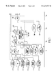
- FIG. 1 shows a schematic block diagram of a device for failsafe signalling of attempted theft of a motor vehicle using an external control unit
- FIG. 2 shows a schematic block diagram of a device for failsafe signalling of attempted theft of a motor vehicle by loading it onto another vehicle and transporting it away;
- FIG. 3 shows a schematic block diagram of a device for failsafe signalling of attempted theft of a motor vehicle by towing it away.
- FIGS. 1 to 3 perform failsafe signalling of different situations where theft is attempted. It is of course possible to implement only one device, or any desired combination of the three devices, in a particular motor vehicle. Preferably, all three illustrated devices are implemented as parts of a combined device which can detect all types of attempted thefts. In this respect, FIGS. 1 to 3 should be regarded as various aspects of one and the same device.
- the hatched function block which is surrounded by a dashed line represents an arithmetic unit 1 with various interfaces for receiving input signals 3 - 8 , 12 - 15 and 24 - 25 .
- the input interfaces comprise digital interfaces at which a respective signal which indicates vehicle states is present, with a digital signal state which indicates that a possible attempt at theft is, or is not, taking place.
- the signals from door contact sensors 3 indicate whether the respective vehicle door is being opened, or is closed.
- complex interfaces are provided, for example for detecting an external control unit.
- an external-use protection system also referred to as travel-authorization system
- travel-authorization system which is present exchanges with the respective control unit, an encrypted message, which is decoded and assessed for correctness.
- the arithmetic unit 1 Via a first signal output S 1 , the arithmetic unit 1 outputs an alarm signal which can trigger a theft alarm system on the vehicle. Via a second output S 4 , the arithmetic unit 1 outputs a theft-signalling signal, which can be transmitted via a wireless long-distance transmission link to a remote monitoring location which carries out appropriate locating and/or immobilization measures of a conventional type when an attempted theft is signalled.
- the devices illustrated according to FIGS. 1 to 3 are capable of detecting the theft scenarios which are still most relevant because of the use of electronic immobilizers (which virtually exclude the possibility of stealing a vehicle on its own axle without possessing original keys).
- Such theft scenarios include bypassing or removal of vehicle control units which relate to operation (in particular the engine control unit) loading the vehicle onto another vehicle and transporting it away, or towing it away.
- the arithmetic unit 1 contains various logic AND and OR elements and ⁇ t time delay elements.
- logic AND and OR elements refer not only to simple logic combinations of a plurality of digital signals, but also to logic combinations at a higher level of abstraction.
- the external control unit detection means 2 interrogatres and decodes an encrypted dialogue between the engine control unit and the external use protection system, to detect whether the original control unit is no longer active (and therefore whether it has been replaced by an external control unit). This complex interrogation procedure then results in the digital information “external control unit present” or not.
- the ⁇ t delay elements are, in the first instance, not customary delay elements, but rather the symbolic representation of the chronological occurrence of the respective signals.
- the logic combination elements and the ⁇ t delay elements can be realized not only as hardware, but also to a certain extent as software in the arithmetic unit 1 .
- the logic combination elements and the ⁇ t delay elements can also be replaced by fuzzy logic, threshold logic, which outputs an item of theft-signalling information starting from a prescribed probability threshold of, for example, greater than 98%, then being located at the end of the decision chain.
- the oval function blocks outside the arithmetic unit 1 represent various vehicle state-monitoring units which are ordinarily present on a vehicle. Each such monitoring unit outputs to the arithmetic unit 1 a signal which is indicative of a vehicle state.
- a contact-controlled outer skin protection sensor system 3 , 6 , 7 which monitors the closed state of the various outer skin elements of the vehicle that are capable of opening (e.g., vehicle doors, hood and tailgate), and a passenger compartment protection sensor 4 (for example an ultrasonic monitoring unit and a conventional towing-away protection 5 ), the prescribed protection sensor system also includes (as shown in FIG.
- a movement sensor which contains an rpm sensor system 25 , an acceleration sensor system, a wheel rotation pulse evaluation unit 30 (for example of an anti-locking system and/or an intelligent combinatorial unit for assessing the respective individual signals) which unit can be implemented, for example, by means of electronic arithmetic circuits and/or a microcontroller.
- the vehicle position can be monitored by means of a locating system 31 , for example using a GPS receiver, and hence the absolute vehicle velocity in space can also be monitored.
- the device of FIG. 1 detects an attempt to break into the vehicle or to tow it away and then activate it using one or more external control units in order to bypass the electronic immobilizer.
- the arithmetic unit 1 senses, as a first signalling condition, whether the vehicle is being towed away or broken into when the vehicle access protection device is activated, i.e. the lock system is armed.
- the output signals of a door contact sensor system 3 , of a passenger compartment protection system 4 , of a towing-away protection 5 , of a bonnet contact 6 and of a tailgate contact 7 are sensed and input to an OR gate 9 in the arithmetic unit 1 .
- the output from gate 9 is input to an AND gate 10 , together with a signal representing the state of the lock system 8 .
- a first signalling-condition signal S 1 is generated, which indicates an attempted theft if the lock system was activated and at least one of the OR-combined signals of the units 3 to 7 (indicative of access to the vehicle) also has a signal state which is indicative of theft.
- This first signalling-condition signal is used directly as an alarm-triggering signal S 1 which triggers the alarm system on the vehicle, since improved protection against faults is not absolutely necessary for this triggering of the alarm. Because the state of the lock system 8 is taken into account via this AND combination 10 , the alarm signal S 1 cannot be produced when the vehicle doors are opened with authorization. In addition, the arithmetic unit 1 detects possible removal of the lock system 8 and then also produces the alarm signal S 1 . If the lock system 8 cannot be deactivated owing to a technical defect, but is to be replaced, to permit this it is possible, for example, to transmit an appropriate message to the monitoring point which then permits the vehicle to be towed away to a workshop.
- an appropriate ⁇ t delay element 11 it is interrogated whether an attempt is being made to activate the vehicle.
- the operating state of ignition line 12 , a starter line 13 , the fuel pump 14 and the vehicle engine 15 are interrogated.
- the four associated signals which are indicative of vehicle states are input to an OR gate 16 in the arithmetic unit 1 , and the resulting signal is then input to an AND gate 17 , together with the (delayed) first signalling-condition signal S 1 , so that an appropriate second signalling-condition signal S 2 is generated at a time t 2 .
- the ⁇ t delay elements here generally also have storage properties so that, for example, after an attempt at breaking into the vehicle the second signalling-condition signal S 2 retains its signal state which is indicative of theft, even if a vehicle door which has previously been forced open has already been closed again.
- the arithmetic unit 1 tests whether an external control unit, for example an external engine control unit, has been installed without permission.
- the arithmetic unit 1 samples the data bus line 19 (which is for example, of a CAN bus present in the vehicle), between the appropriate control unit which is involved in the electronic immobilization protection and the travel-authorization system itself, for the encrypted authorization data exchanged between the latter.
- the data bus line 19 which is for example, of a CAN bus present in the vehicle
- the exchange can be carried out in a workshop after the vehicle has been towed away.
- Such towing away can be indicated to the monitoring point in a special signalling mode, so that the latter then permits the towing-away procedure without evaluating it as an attempted theft.
- the digital signal from the external control unit detection unit 2 which contains the information indicating whether at least one external control unit has been used, is then input to an AND gate 20 with the second signalling-condition signal S 2 , resulting in a third signalling-condition signal S 3 at a time t 3 .
- the arithmetic unit 1 checks whether the travel-authorization system 22 is activated or, at any rate, was activated before the installation of an external control unit.
- the appropriate information signal is subjected to an AND operation 23 with the third signalling-condition signal S 3 .
- the resulting signal represents the theft-signalling signal S 4 which is output by the arithmetic unit 1 at a time t 4 and which is passed on via a wireless transmission link to the central monitoring point (not illustrated) outside the vehicle.
- the theft-signalling signal S 4 is clearly provided with extremely effective failsafe protection, since it indicates an attempt at theft only if the signal states of the various abovementioned vehicle state signals input to the arithmetic unit 1 are present in quite specific theft-signalling combinations, such as are characterized by the OR and the AND operations and by the correct time sequence, as symbolized by the various ⁇ t delay elements.
- the signal of a vehicle speed sensor system 24 can also be taken into account, as indicated by broken lines in FIG. 1, for the last AND combination which makes this signal S 4 available.
- the theft-signalling information S 4 is produced only when the vehicle is moving at a specific minimum speed.
- a service key may be provided which is handed out to the authorized personnel and which is detected by the arithmetic unit 1 after it has been inserted into the ignition lock.
- the arithmetic unit 1 is then able to suppress the transmission of this signal S 4 or, together with this signal S 4 , output an item of additional information with which the monitoring point can detect that the manipulation on the vehicle is authorized.
- FIG. 2 shows a failsafe device for signalling the unauthorized loading and transporting away of a vehicle on another vehicle as an attempted theft.
- components which are functionally identical components to those of FIG. 1, have identical reference symbols. As stated previously, the two devices may also be integrated to form a combined device.
- the state signal of the lock system 8 is combined in the AND gate 10 with the output signal of the OR gate 9 to produce the first signalling-condition signal S 1 at a time t 5 .
- the signals of an rpm sensor system 25 , the towing-away protection 5 , an altimeter 26 , a spring-extension meter 27 as well as of the tailgate contact 7 and the bonnet contact 6 , which are indicative of vehicle states, are fed to the OR gate 9 . If one of these OR conditions is fulfilled when the lock system 8 is armed, the first signalling-condition signal S 1 indicates a theft, which triggers the vehicle alarm. In this case, the first signalling-condition S 1 specifically indicates a vehicle-loading procedure.
- the first signal S 1 is combined in an OR operation 28 with the signals of the rpm sensor system 25 , a wheel rpm sensor system 30 , the altimeter 26 and the spring-extension meter 27 .
- the four last-mentioned signals serve to detect the loading of the vehicle onto another vehicle.
- the second signal S 2 results from this OR combination 28 at a time t 6 .
- the second signal S 2 is subjected to an OR gate 29 with the output signal of a GPS receiver 31 , which contains information on the absolute vehicle velocity in space.
- OR operation 29 a theft is signalled if the absolute velocity exceeds a prescribed minimum velocity.
- the result of the OR gate 29 is then input to an AND gate 32 , together with two further signals at a time t 7 in order to produce the theft indicating signal S 4 .
- One of the two further signals indicates the state of the travel-authorization system 22 , and the other indicates whether the travel-authorization system 22 is in a loading operating mode 33 .
- This operating mode is provided for the travel-authorization system 22 in order to permit authorized transport of the vehicle by rail or ship without triggering the theft-signalling signal S 4 .
- the state signal which is associated with the loading operating mode 33 is inverted in an inverter 34 before being fed to the AND operation 32 .
- the device shown in FIG. 3 can be implemented separately, or as a further component of the devices of FIG. 1 and/or 2 .
- the arrangement of FIG. 3 detects attempted thefts by a towing-away.
- Functionally identical components to those in devices 1 and 2 have the same reference symbols, and for their explanation the description in FIGS. 1 and 2 can be referred to.
- FIG. 3 In FIG.
- the signals of the door contacts 3 of the passenger compartment protection 4 , the towing-away protection 5 , the altimeter 26 , the spring-extension meter 27 , the tailgate contact 7 and the bonnet contact 6 are input to an OR operator 9 of the arithmetic unit 1 , in order to detect whether the vehicle has been broken into and/or whether someone is moving in the passenger compartment of the vehicle and/or the vehicle has been lifted up.
- the first signalling-condition signal S 1 is then produced at a time t 8 , which signal is indicative of theft and triggers the alarm on the vehicle.
- the first signalling-condition signal S 1 of the AND operation 17 is combined with the output signal in the OR operation 16 .
- the state signal of a handbrake 35 is OR-combined with the state signal of an automatic gearbox 36 .
- a towing-away procedure is indicated by the handbrake being released and/or the automatic gearbox being moved out of its parking position.
- the AND operation 17 produces the second signalling-condition signal S 2 which, in the subsequent time period, symbolized by the ⁇ t delay element 18 , is then subjected to an OR operation 37 with the absolute movement signal of the GPS receiver 31 , in order to cause a theft to be signalled when the signal state which is indicative of theft occurs for at least one of these two signals.
- the signal resulting from the OR operation 37 is then logically combined in the subsequent AND operation 32 with the state signal of the travel-authorization system 22 at a time t 10 , in order to produce the theft-signalling signal S 4 .
- the theft-signalling information which is preferably transmitted to a remote monitoring point is produced in a very failsafe fashion.
Landscapes
- Engineering & Computer Science (AREA)
- Mechanical Engineering (AREA)
- Burglar Alarm Systems (AREA)
Applications Claiming Priority (2)
| Application Number | Priority Date | Filing Date | Title |
|---|---|---|---|
| DE19644879 | 1996-10-29 | ||
| DE19644879A DE19644879C1 (de) | 1996-10-29 | 1996-10-29 | Verfahren und Vorrichtung zur Diebstahlmeldung für ein Kraftfahrzeug |
Publications (1)
| Publication Number | Publication Date |
|---|---|
| US6232873B1 true US6232873B1 (en) | 2001-05-15 |
Family
ID=7810279
Family Applications (1)
| Application Number | Title | Priority Date | Filing Date |
|---|---|---|---|
| US08/960,202 Expired - Fee Related US6232873B1 (en) | 1996-10-29 | 1997-10-29 | Method and apparatus for signalling theft for a motor vehicle |
Country Status (6)
| Country | Link |
|---|---|
| US (1) | US6232873B1 (de) |
| EP (1) | EP0839698B1 (de) |
| JP (1) | JPH10129422A (de) |
| DE (1) | DE19644879C1 (de) |
| ES (1) | ES2181968T3 (de) |
| ZA (1) | ZA979388B (de) |
Cited By (27)
| Publication number | Priority date | Publication date | Assignee | Title |
|---|---|---|---|---|
| US6388568B1 (en) * | 2000-07-18 | 2002-05-14 | Sumitomo Rubber Industries | Apparatus and method for alarming decrease in tire air-pressure |
| US6525658B2 (en) * | 2001-06-11 | 2003-02-25 | Ensco, Inc. | Method and device for event detection utilizing data from a multiplicity of sensor sources |
| US20030095039A1 (en) * | 2001-11-19 | 2003-05-22 | Toshio Shimomura | Vehicle anti-theft device and anti-theft information center |
| US20030182032A1 (en) * | 2002-03-25 | 2003-09-25 | Sun Microsystems, Inc. | Vehicle mode manager |
| US20040075539A1 (en) * | 2002-01-22 | 2004-04-22 | Paul-Andre Savoie | Vehicle monitoring system |
| US20040201520A1 (en) * | 2000-05-17 | 2004-10-14 | Omega Patents, L.L.C. | Vehicle tracker with user notifications and associated methods |
| US6822559B2 (en) * | 2000-09-20 | 2004-11-23 | Siemens Aktiengesellschaft | Security system for a motor vehicle |
| US20050222732A1 (en) * | 2004-03-31 | 2005-10-06 | Nissan Technical Center North America, Inc. | Tailgate ajar and security monitoring system |
| US20060129282A1 (en) * | 2004-11-30 | 2006-06-15 | Omega Patents, L.L.C. | Vehicle control system and associated method for counteracting rogue command |
| US20060129284A1 (en) * | 2004-11-30 | 2006-06-15 | Omega Patents, L.L.C. | Remote vehicle control system and associated method for counteracting rogue command |
| US7859392B2 (en) | 2006-05-22 | 2010-12-28 | Iwi, Inc. | System and method for monitoring and updating speed-by-street data |
| US7876205B2 (en) | 2007-10-02 | 2011-01-25 | Inthinc Technology Solutions, Inc. | System and method for detecting use of a wireless device in a moving vehicle |
| US7899610B2 (en) | 2006-10-02 | 2011-03-01 | Inthinc Technology Solutions, Inc. | System and method for reconfiguring an electronic control unit of a motor vehicle to optimize fuel economy |
| US7999670B2 (en) | 2007-07-02 | 2011-08-16 | Inthinc Technology Solutions, Inc. | System and method for defining areas of interest and modifying asset monitoring in relation thereto |
| US8188887B2 (en) | 2009-02-13 | 2012-05-29 | Inthinc Technology Solutions, Inc. | System and method for alerting drivers to road conditions |
| US20130278446A1 (en) * | 2012-04-19 | 2013-10-24 | Hon Hai Precision Industry Co., Ltd. | Vehicular observation system, apparatus, and server for the vehicular observation system |
| US8577703B2 (en) | 2007-07-17 | 2013-11-05 | Inthinc Technology Solutions, Inc. | System and method for categorizing driving behavior using driver mentoring and/or monitoring equipment to determine an underwriting risk |
| US8666590B2 (en) | 2007-06-22 | 2014-03-04 | Inthinc Technology Solutions, Inc. | System and method for naming, filtering, and recall of remotely monitored event data |
| US8688180B2 (en) | 2008-08-06 | 2014-04-01 | Inthinc Technology Solutions, Inc. | System and method for detecting use of a wireless device while driving |
| US8818618B2 (en) | 2007-07-17 | 2014-08-26 | Inthinc Technology Solutions, Inc. | System and method for providing a user interface for vehicle monitoring system users and insurers |
| US8825277B2 (en) | 2007-06-05 | 2014-09-02 | Inthinc Technology Solutions, Inc. | System and method for the collection, correlation and use of vehicle collision data |
| US8892341B2 (en) | 2009-02-13 | 2014-11-18 | Inthinc Technology Solutions, Inc. | Driver mentoring to improve vehicle operation |
| US8963702B2 (en) | 2009-02-13 | 2015-02-24 | Inthinc Technology Solutions, Inc. | System and method for viewing and correcting data in a street mapping database |
| US9067565B2 (en) | 2006-05-22 | 2015-06-30 | Inthinc Technology Solutions, Inc. | System and method for evaluating driver behavior |
| US9117246B2 (en) | 2007-07-17 | 2015-08-25 | Inthinc Technology Solutions, Inc. | System and method for providing a user interface for vehicle mentoring system users and insurers |
| US9129460B2 (en) | 2007-06-25 | 2015-09-08 | Inthinc Technology Solutions, Inc. | System and method for monitoring and improving driver behavior |
| US9172477B2 (en) | 2013-10-30 | 2015-10-27 | Inthinc Technology Solutions, Inc. | Wireless device detection using multiple antennas separated by an RF shield |
Families Citing this family (7)
| Publication number | Priority date | Publication date | Assignee | Title |
|---|---|---|---|---|
| DE19853603A1 (de) * | 1998-11-20 | 2000-06-08 | Bosch Gmbh Robert | Benutzererkennende Diebstahlschutzeinrichtung |
| JP2001014592A (ja) * | 1999-06-28 | 2001-01-19 | Oki Software Kk | 移動体位置監視システム |
| DE60118980T2 (de) * | 2000-07-05 | 2007-01-04 | Denso Corp., Kariya | Diebstahlsicherung für Fahrzeuge mit ferngesteuerter Motorstartfunktion |
| DE10100806A1 (de) * | 2001-01-10 | 2002-07-11 | Delphi Tech Inc | System und Verfahren zur Überwachung eines von Wänden umschlossenen Raumes |
| DE10238039A1 (de) * | 2002-08-20 | 2004-03-04 | Delphi Technologies, Inc., Troy | Verfahren und Vorrichtung zur Überwachung eines Kraftfahrzeugs |
| JP6723279B2 (ja) * | 2018-03-20 | 2020-07-15 | 本田技研工業株式会社 | 車載認証装置、方法、およびプログラム |
| DE102021205844B3 (de) | 2021-06-10 | 2022-09-29 | Volkswagen Aktiengesellschaft | Verfahren zum Detektieren eines digitalen Angriffs auf ein fahrdynamisches Steuergerät eines Kraftfahrzeugs, Computerprogrammprodukt sowie Angriffsdetektionssystem |
Citations (12)
| Publication number | Priority date | Publication date | Assignee | Title |
|---|---|---|---|---|
| GB2012092A (en) | 1978-01-06 | 1979-07-18 | American District Telegraph Co | Alarm system |
| FR2523340A1 (fr) | 1982-03-15 | 1983-09-16 | Electrotelephonie | Dispositif de declenchement d'alarme et notamment dispositif antivol pour vehicule automobile |
| EP0388756A2 (de) | 1989-03-24 | 1990-09-26 | Vincenzo Di Dio Russo | Vorrichtung zur Kraftfahrzeugdiebstahlsicherung mit Anordnung zur Fernanzeige eines Einbruchversuchs |
| JPH02246860A (ja) | 1989-03-16 | 1990-10-02 | Daifuku Co Ltd | 台車利用の搬送装置 |
| DE3926983A1 (de) | 1989-08-16 | 1991-02-21 | Bosch Gmbh Robert | Einen oder mehrere sensoren enthaltende fahrzeugalarmvorrichtung |
| US5181010A (en) * | 1988-08-04 | 1993-01-19 | Chick James S | Automotive security system with discrimination between tampering and attack |
| DE4203865A1 (de) | 1991-08-30 | 1993-03-04 | Erich Matouschek | Alarm- und meldeanlage fuer fahrzeuge |
| EP0366378B1 (de) | 1988-10-26 | 1993-08-25 | Harada Industry Co., Ltd. | Kraftfahrzeugdiebstahlsicherungsvorrichtung |
| WO1993024911A1 (en) | 1992-06-01 | 1993-12-09 | Trackmobile | Vehicle tracking system |
| DE4243415C1 (de) | 1992-12-17 | 1994-04-14 | Detecon Gmbh | Alarmsystem für bewegliche Güter |
| EP0641693A1 (de) | 1993-08-04 | 1995-03-08 | Depromax Limited | Drahtlose Digitalcode-Anti-Diebstahlvorrichtung |
| DE4416118C1 (de) | 1994-05-06 | 1995-10-19 | Porsche Ag | Verfahren zum Entriegeln einer aktivierten Wegfahrsicherung eines Fahrzeuges |
-
1996
- 1996-10-29 DE DE19644879A patent/DE19644879C1/de not_active Expired - Fee Related
-
1997
- 1997-10-15 EP EP97117847A patent/EP0839698B1/de not_active Expired - Lifetime
- 1997-10-15 ES ES97117847T patent/ES2181968T3/es not_active Expired - Lifetime
- 1997-10-20 ZA ZA9709388A patent/ZA979388B/xx unknown
- 1997-10-28 JP JP33225797A patent/JPH10129422A/ja active Pending
- 1997-10-29 US US08/960,202 patent/US6232873B1/en not_active Expired - Fee Related
Patent Citations (12)
| Publication number | Priority date | Publication date | Assignee | Title |
|---|---|---|---|---|
| GB2012092A (en) | 1978-01-06 | 1979-07-18 | American District Telegraph Co | Alarm system |
| FR2523340A1 (fr) | 1982-03-15 | 1983-09-16 | Electrotelephonie | Dispositif de declenchement d'alarme et notamment dispositif antivol pour vehicule automobile |
| US5181010A (en) * | 1988-08-04 | 1993-01-19 | Chick James S | Automotive security system with discrimination between tampering and attack |
| EP0366378B1 (de) | 1988-10-26 | 1993-08-25 | Harada Industry Co., Ltd. | Kraftfahrzeugdiebstahlsicherungsvorrichtung |
| JPH02246860A (ja) | 1989-03-16 | 1990-10-02 | Daifuku Co Ltd | 台車利用の搬送装置 |
| EP0388756A2 (de) | 1989-03-24 | 1990-09-26 | Vincenzo Di Dio Russo | Vorrichtung zur Kraftfahrzeugdiebstahlsicherung mit Anordnung zur Fernanzeige eines Einbruchversuchs |
| DE3926983A1 (de) | 1989-08-16 | 1991-02-21 | Bosch Gmbh Robert | Einen oder mehrere sensoren enthaltende fahrzeugalarmvorrichtung |
| DE4203865A1 (de) | 1991-08-30 | 1993-03-04 | Erich Matouschek | Alarm- und meldeanlage fuer fahrzeuge |
| WO1993024911A1 (en) | 1992-06-01 | 1993-12-09 | Trackmobile | Vehicle tracking system |
| DE4243415C1 (de) | 1992-12-17 | 1994-04-14 | Detecon Gmbh | Alarmsystem für bewegliche Güter |
| EP0641693A1 (de) | 1993-08-04 | 1995-03-08 | Depromax Limited | Drahtlose Digitalcode-Anti-Diebstahlvorrichtung |
| DE4416118C1 (de) | 1994-05-06 | 1995-10-19 | Porsche Ag | Verfahren zum Entriegeln einer aktivierten Wegfahrsicherung eines Fahrzeuges |
Cited By (39)
| Publication number | Priority date | Publication date | Assignee | Title |
|---|---|---|---|---|
| US20040201520A1 (en) * | 2000-05-17 | 2004-10-14 | Omega Patents, L.L.C. | Vehicle tracker with user notifications and associated methods |
| US6888495B2 (en) * | 2000-05-17 | 2005-05-03 | Omega Patents, L.L.C. | Vehicle tracker with user notifications and associated methods |
| US6388568B1 (en) * | 2000-07-18 | 2002-05-14 | Sumitomo Rubber Industries | Apparatus and method for alarming decrease in tire air-pressure |
| US6822559B2 (en) * | 2000-09-20 | 2004-11-23 | Siemens Aktiengesellschaft | Security system for a motor vehicle |
| US6525658B2 (en) * | 2001-06-11 | 2003-02-25 | Ensco, Inc. | Method and device for event detection utilizing data from a multiplicity of sensor sources |
| US20030095039A1 (en) * | 2001-11-19 | 2003-05-22 | Toshio Shimomura | Vehicle anti-theft device and anti-theft information center |
| US6879247B2 (en) | 2001-11-19 | 2005-04-12 | Denso Corporation | Vehicle anti-theft device and anti-theft information center |
| US20040075539A1 (en) * | 2002-01-22 | 2004-04-22 | Paul-Andre Savoie | Vehicle monitoring system |
| US20030182032A1 (en) * | 2002-03-25 | 2003-09-25 | Sun Microsystems, Inc. | Vehicle mode manager |
| EP1349117A3 (de) * | 2002-03-25 | 2004-05-12 | Sun Microsystems, Inc. | Fahrzeugzustands-Management-System |
| US6928344B2 (en) | 2002-03-25 | 2005-08-09 | Sun Microsystems, Inc. | Vehicle mode manager |
| US7400971B2 (en) | 2004-03-31 | 2008-07-15 | Nissan Technical Center North America, Inc. | Tailgate ajar and security monitoring system |
| US20050222732A1 (en) * | 2004-03-31 | 2005-10-06 | Nissan Technical Center North America, Inc. | Tailgate ajar and security monitoring system |
| US20060129282A1 (en) * | 2004-11-30 | 2006-06-15 | Omega Patents, L.L.C. | Vehicle control system and associated method for counteracting rogue command |
| US20060129284A1 (en) * | 2004-11-30 | 2006-06-15 | Omega Patents, L.L.C. | Remote vehicle control system and associated method for counteracting rogue command |
| US7729814B2 (en) | 2004-11-30 | 2010-06-01 | Omega Patents, L.L.C. | Vehicle control system and associated method for counteracting rogue command |
| US7734382B2 (en) | 2004-11-30 | 2010-06-08 | Omega Patents, L.L.C. | Remote vehicle control system and associated method for counteracting rogue command |
| US8630768B2 (en) | 2006-05-22 | 2014-01-14 | Inthinc Technology Solutions, Inc. | System and method for monitoring vehicle parameters and driver behavior |
| US10522033B2 (en) | 2006-05-22 | 2019-12-31 | Inthinc LLC | Vehicle monitoring devices and methods for managing man down signals |
| US9847021B2 (en) | 2006-05-22 | 2017-12-19 | Inthinc LLC | System and method for monitoring and updating speed-by-street data |
| US9067565B2 (en) | 2006-05-22 | 2015-06-30 | Inthinc Technology Solutions, Inc. | System and method for evaluating driver behavior |
| US7859392B2 (en) | 2006-05-22 | 2010-12-28 | Iwi, Inc. | System and method for monitoring and updating speed-by-street data |
| US8890717B2 (en) | 2006-05-22 | 2014-11-18 | Inthinc Technology Solutions, Inc. | System and method for monitoring and updating speed-by-street data |
| US7899610B2 (en) | 2006-10-02 | 2011-03-01 | Inthinc Technology Solutions, Inc. | System and method for reconfiguring an electronic control unit of a motor vehicle to optimize fuel economy |
| US8825277B2 (en) | 2007-06-05 | 2014-09-02 | Inthinc Technology Solutions, Inc. | System and method for the collection, correlation and use of vehicle collision data |
| US8666590B2 (en) | 2007-06-22 | 2014-03-04 | Inthinc Technology Solutions, Inc. | System and method for naming, filtering, and recall of remotely monitored event data |
| US9129460B2 (en) | 2007-06-25 | 2015-09-08 | Inthinc Technology Solutions, Inc. | System and method for monitoring and improving driver behavior |
| US7999670B2 (en) | 2007-07-02 | 2011-08-16 | Inthinc Technology Solutions, Inc. | System and method for defining areas of interest and modifying asset monitoring in relation thereto |
| US8818618B2 (en) | 2007-07-17 | 2014-08-26 | Inthinc Technology Solutions, Inc. | System and method for providing a user interface for vehicle monitoring system users and insurers |
| US8577703B2 (en) | 2007-07-17 | 2013-11-05 | Inthinc Technology Solutions, Inc. | System and method for categorizing driving behavior using driver mentoring and/or monitoring equipment to determine an underwriting risk |
| US9117246B2 (en) | 2007-07-17 | 2015-08-25 | Inthinc Technology Solutions, Inc. | System and method for providing a user interface for vehicle mentoring system users and insurers |
| US8890673B2 (en) | 2007-10-02 | 2014-11-18 | Inthinc Technology Solutions, Inc. | System and method for detecting use of a wireless device in a moving vehicle |
| US7876205B2 (en) | 2007-10-02 | 2011-01-25 | Inthinc Technology Solutions, Inc. | System and method for detecting use of a wireless device in a moving vehicle |
| US8688180B2 (en) | 2008-08-06 | 2014-04-01 | Inthinc Technology Solutions, Inc. | System and method for detecting use of a wireless device while driving |
| US8892341B2 (en) | 2009-02-13 | 2014-11-18 | Inthinc Technology Solutions, Inc. | Driver mentoring to improve vehicle operation |
| US8963702B2 (en) | 2009-02-13 | 2015-02-24 | Inthinc Technology Solutions, Inc. | System and method for viewing and correcting data in a street mapping database |
| US8188887B2 (en) | 2009-02-13 | 2012-05-29 | Inthinc Technology Solutions, Inc. | System and method for alerting drivers to road conditions |
| US20130278446A1 (en) * | 2012-04-19 | 2013-10-24 | Hon Hai Precision Industry Co., Ltd. | Vehicular observation system, apparatus, and server for the vehicular observation system |
| US9172477B2 (en) | 2013-10-30 | 2015-10-27 | Inthinc Technology Solutions, Inc. | Wireless device detection using multiple antennas separated by an RF shield |
Also Published As
| Publication number | Publication date |
|---|---|
| EP0839698A2 (de) | 1998-05-06 |
| DE19644879C1 (de) | 1997-11-20 |
| ES2181968T3 (es) | 2003-03-01 |
| JPH10129422A (ja) | 1998-05-19 |
| EP0839698B1 (de) | 2002-08-14 |
| EP0839698A3 (de) | 1999-12-08 |
| ZA979388B (en) | 1998-05-12 |
Similar Documents
| Publication | Publication Date | Title |
|---|---|---|
| US6232873B1 (en) | Method and apparatus for signalling theft for a motor vehicle | |
| US11878652B2 (en) | Vehicle remote control system | |
| JP3832347B2 (ja) | 車両の盗難防止装置及びプログラム | |
| US5382948A (en) | Vehicular security system with remote signalling for auto carjacking functions | |
| JP4136649B2 (ja) | 車両用盗難防止装置及び車両の制御方法 | |
| US20040046639A1 (en) | Device for operating a motor vehicle without a key | |
| US4933664A (en) | Theft prevention device for automobiles | |
| ITMI942148A1 (it) | Sistema di allarme per veicoli | |
| JP3692593B2 (ja) | 車両盗難防止装置 | |
| US3967239A (en) | Vehicle anti-theft alarm circuit | |
| JPH04230451A (ja) | 中央鎖錠装置および盗難警報装置を備えた車両 | |
| JP3578017B2 (ja) | 車両用ロック装置 | |
| JP3095116B2 (ja) | 車両用多重通信システムにおける警報装置及び盗難防止装置 | |
| JP2006199268A (ja) | 盗難防止装置 | |
| JP3137443B2 (ja) | 盗難防止装置 | |
| KR0128854Y1 (ko) | 자동차의 도난 방지용 카메라 | |
| JP3624795B2 (ja) | 車両用盗難防止装置 | |
| JP3181463U (ja) | 車両用防犯装置 | |
| JPH0553666B2 (de) | ||
| JPH09188225A (ja) | 自動車用盗難防止装置 | |
| KR200345101Y1 (ko) | 초음파센서를 이용한 차량 도난 방지 장치 | |
| KR0183577B1 (ko) | 제동 장치에 의한 차량 도난 방지 방치 | |
| RU2267414C2 (ru) | Способ работы системы безопасности автомобиля | |
| KR100195479B1 (ko) | 자동차 도난방지장치 | |
| RU2372225C1 (ru) | Узел блокирования функциональных органов транспортного средства и способ его работы |
Legal Events
| Date | Code | Title | Description |
|---|---|---|---|
| FEPP | Fee payment procedure |
Free format text: PAYOR NUMBER ASSIGNED (ORIGINAL EVENT CODE: ASPN); ENTITY STATUS OF PATENT OWNER: LARGE ENTITY |
|
| AS | Assignment |
Owner name: DAIMLER-BENZ AG, GERMANY Free format text: ASSIGNMENT OF ASSIGNORS INTEREST;ASSIGNORS:DILZ, BERNHARDT;KOLLBACH, DIETBERT;ROBITSCHKO, PETER;REEL/FRAME:009192/0051 Effective date: 19971104 |
|
| FEPP | Fee payment procedure |
Free format text: PAYOR NUMBER ASSIGNED (ORIGINAL EVENT CODE: ASPN); ENTITY STATUS OF PATENT OWNER: LARGE ENTITY Free format text: PAYER NUMBER DE-ASSIGNED (ORIGINAL EVENT CODE: RMPN); ENTITY STATUS OF PATENT OWNER: LARGE ENTITY |
|
| AS | Assignment |
Owner name: DAIMLERCHRYSLER AG, GERMANY Free format text: CHANGE OF NAME;ASSIGNOR:DAIMLER-BENZ AKTIENGESELLSCHAFT;REEL/FRAME:011454/0695 Effective date: 19990108 |
|
| FPAY | Fee payment |
Year of fee payment: 4 |
|
| REMI | Maintenance fee reminder mailed | ||
| FPAY | Fee payment |
Year of fee payment: 8 |
|
| SULP | Surcharge for late payment |
Year of fee payment: 7 |
|
| REMI | Maintenance fee reminder mailed | ||
| LAPS | Lapse for failure to pay maintenance fees | ||
| STCH | Information on status: patent discontinuation |
Free format text: PATENT EXPIRED DUE TO NONPAYMENT OF MAINTENANCE FEES UNDER 37 CFR 1.362 |
|
| FP | Lapsed due to failure to pay maintenance fee |
Effective date: 20130515 |