US6312285B1 - Panel mounting system for electrical connectors - Google Patents
Panel mounting system for electrical connectors Download PDFInfo
- Publication number
- US6312285B1 US6312285B1 US09/257,623 US25762399A US6312285B1 US 6312285 B1 US6312285 B1 US 6312285B1 US 25762399 A US25762399 A US 25762399A US 6312285 B1 US6312285 B1 US 6312285B1
- Authority
- US
- United States
- Prior art keywords
- housing
- panel
- opening
- locating
- connector
- Prior art date
- Legal status (The legal status is an assumption and is not a legal conclusion. Google has not performed a legal analysis and makes no representation as to the accuracy of the status listed.)
- Expired - Fee Related
Links
Images


Classifications
-
- H—ELECTRICITY
- H01—ELECTRIC ELEMENTS
- H01R—ELECTRICALLY-CONDUCTIVE CONNECTIONS; STRUCTURAL ASSOCIATIONS OF A PLURALITY OF MUTUALLY-INSULATED ELECTRICAL CONNECTING ELEMENTS; COUPLING DEVICES; CURRENT COLLECTORS
- H01R13/00—Details of coupling devices of the kinds covered by groups H01R12/70 or H01R24/00 - H01R33/00
- H01R13/73—Means for mounting coupling parts to apparatus or structures, e.g. to a wall
- H01R13/74—Means for mounting coupling parts in openings of a panel
Definitions
- This invention generally relates to the art of electrical connectors and, particularly, to a system for mounting an electrical connector in an opening in a panel or other planar substrate.
- Panel mounted electrical connectors are known in the art, and such a connector generally includes a housing mounting a plurality of terminals for mating with a complementary connector.
- the housing may be mounted to a generally rigid panel for mating of the connector with the complementary connector through an opening in the panel, or the housing may be mounted on the panel simply for structural or support purposes within a circuit interconnection system.
- Various means have been used to mount the connector to a panel, such as mounting clips or brackets operatively associated between the connector housing and the panel to mount and hold the connector to the panel.
- the connector housing is inserted into the opening in the panel to an insertion position and then moved relative to the panel, within the opening, to a final mounted position whereat the connector is latched by latch means directly on the connector housing.
- latch means for holding the connector in the opening in the panel takes up valuable “real estate” on the panel and weakens the structure.
- the latch means often requires the connector to be unnecessarily spaced from any surrounding component with a weakened panel.
- the latch means may include extraneous “outboard” latch openings in the panel. Engaging flanges or lugs often are used on one or more sides of the connector housing to hold the housing in the panel openings, and latches often project from still other sides of the connector housing to unnecessarily enlarge the connector envelope.
- the present invention is directed to solving the problems discussed above in a panel mounting system for an electrical connector, and particularly in the latch means for holding the connector in its final mounted position.
- An object, therefore, of the invention is to provide a new and improved system for mounting an electrical connector in a panel or other planar substrate.
- a panel has first and second sides and an opening, with at least one locating slot extending radially from the opening.
- a connector has a housing insertable from the first side of the panel along an axis to an insertion position into the opening in the panel.
- the housing includes at least one radially extending locating flange at one side of the housing for passing through the locating slot of the opening as the housing is inserted thereinto.
- the housing also includes at least one radially extending stop flange spaced axially and transversely from the locating flange for abutting the first side of the panel when the locating flange clears the second side of the panel.
- the housing is movable generally parallel to the panel from the insertion position to a latched position.
- a latch arm projects from the one side of the connector housing and is engageable with a latch slot extending radially from the opening in the panel when the housing is in the latched position.
- the locating slot performs a dual function and comprises the latch slot for the latch arm.
- the latch arm comprises a flexible cantilevered latch arm extending generally parallel to the axis of insertion of the connector housing.
- the latch arm comprises a flexible cantilevered latch arm extending generally parallel to the panel.
- the latch arm comprises a flexible latch bar extending between a pair of the stop flanges.
- the latch bar includes a tab supporting a projection, and the latch bar torsionally moves to urge the projection into engagement with the latch slot.
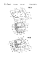
- FIG. 1 is an exploded perspective view of a panel with an opening therein, along with an electrical connector insertable into the opening, according to a first embodiment of the invention
- FIG. 2 is a perspective view of the connector inserted into the opening in the panel to its insertion position
- FIG. 3 is a perspective view of the connector moved from its insertion position to its final latched position
- FIG. 4 is a vertical section through the connector in the area of the latch arms thereof;
- FIG. 5 is a perspective view of a connector according to a second embodiment of the invention.
- FIG. 6 is a front elevational view of the connector of FIG. 5;
- FIG. 7 is a plan view of the connector of FIGS. 5 and 6 inserted into an opening in a panel to its insertion position;
- FIG. 8 is a view similar to that of FIG. 7, with the connector moved from its insertion position to its final latched position;
- FIG. 9 is a perspective view of a connector according to a third embodiment of the invention.
- FIG. 10 is a perspective view looking toward the rear of the connector as viewed in FIG. 9;
- FIG. 11 is a plan view of a panel having an opening for receiving the connector of FIGS. 9 and 10;
- FIG. 12 is a perspective view of the connector of FIGS. 9 and 10 inserted into the opening in the panel of FIG. 11 and moved to its final latched position;
- FIG. 13 is a perspective view of the assembly of FIG. 12, looking at the opposite side of the panel.
- a first embodiment of the invention herein is directed to a system for mounting an electrical connector, generally designated 10 , in an opening 12 in a panel, generally designated 14 .
- the panel has a top side 14 a and a bottom side 14 b .
- the opening is generally T-shaped to define a pair of elongated locating slots 16 at opposite ends of the cross portion of the T-shaped configuration.
- a pair of additional locating slots 18 are located at each opposite side of the leg portion of the T-shaped configuration of the slot, intermediate the ends thereof.
- Connector 10 includes a one-piece housing, generally designated 20 , unitarily molded of dielectric material such as plastic or the like.
- the housing is box-shaped to define a pair of first opposite side walls 24 and a pair of second side walls 26 which define a rectangular receptacle 28 for receiving a complementary mating connector.
- the mouth of receptacle 28 is chamfered, as at 28 a , to facilitate inserting a mating connector thereinto.
- the housing has a bottom wall 30 (FIG. 4) which mounts a plurality of terminals, generally designated 32 .
- the terminals have contact pins 32 a projecting into receptacle 28 for engaging the terminals of the mating connector.
- the terminals have tail portions 32 b projecting from bottom wall 30 exteriorly of the housing for insertion into appropriate holes in a printed circuit board or into another connecting device.
- the invention herein is not limited to a board-mounted connector.
- All of the mounting and latching components on connector housing 20 are located on the outsides of first side walls 24 , as seen by the outside of the one side wall 24 visible in FIGS. 1-3. That leaves the outsides of second side walls 26 totally unencumbered and allows the connector to be mounted closely to other components.
- three locating flanges 34 and 36 project outwardly from each side wall 24 .
- the tops of the locating flanges are chamfered to facilitate inserting the connector housing into the opening in the panel.
- the bottoms of the located flanges are abrupt for abutting against top surface 14 a of panel 14 when the connector is in its final latched position, as described hereinafter.
- Three stop flanges 38 also project outwardly from the outside of each side wall 24 for abutting bottom side 14 b of the panel when the connector is in its final latched position.
- the stop flanges are spaced axially and transversely of locating flanges 34 and 36 .
- the locating flanges and the stop flanges are molded integrally with the housing.
- an integrally molded latch arm 40 also projects outwardly from the outside of each side wall 24 .
- each latch arm is cantilevered from its respective side wall so that the latch arm can flex in the direction of double-headed arrows “A” (FIG. 4 ).
- the cantilevered latch arms extend in the insertion direction of the connector as will be apparent hereinafter.
- the tops of the latch arms are chamfered.
- Connector 10 is inserted into opening 12 in panel 14 in a first linear direction from the bottom side of the panel along an axis in the direction of arrow “B” (FIG. 1 ).
- Locating flanges 34 and 36 and stop flanges 38 extend outwardly of the housing radially of this direction.
- locating flanges 34 pass through locating slots 18
- locating flanges 36 pass through locating slots 16 until all of the locating flanges clear the top side 14 a of the panel.
- latch arms 40 are resiliently flexed inwardly by engagement with the edges of opening 12 between locating slots 16 and 18 .
- the connector is moved in a second linear direction as indicated by arrow “C” (FIG. 2) generally perpendicular to the insertion direction “B” until the connector reaches its final latched position shown in FIG. 3 .
- latch arms 40 become aligned with locating slots 18 , and the flexible latch arms “snap” back outwardly into the locating slots to lock the connector in its final latched position.
- locating flanges 34 and 36 abut top side 14 a of panel 14 and stop flanges 38 abut bottom side 14 b of the panel. Therefore, the locating flanges and stop flanges lock the connector axially within the opening in the panel, and latch arms 40 lock the connector radially within the opening.
- FIGS. 5-8 show a second embodiment of an electrical connector, generally designated 10 a , embodying the concepts of the invention. Like reference numerals have been applied in FIGS. 5-8 corresponding to like components described above regarding connector 10 in FIGS. 1-4.
- connector 10 a includes a one-piece housing, generally designated 20 a , having a pair of opposite side walls 24 . Locating flanges 34 a , 34 b project from opposite side walls 24 . Stop flanges 38 also project from the two side walls 24 . As with the first embodiment, the stop flanges are spaced axially and transversely from the locating flanges.
- An integrally molded latch arm 40 a also is disposed at one of the side walls. The latch arm is cantilevered from one of the stop flanges 38 and includes a latch projection 41 at its distal end. Latch arm 40 a extends generally parallel to the panel and generally perpendicular to the insertion direction of the connector into the panel.
- Protector bar 39 is attached to stop flanges 38 and extends parallel to the latch arm 40 a . The protector bar 39 helps to prevent the latch projection 41 from being removed from the locating slot 16 and protects the latch arm 40 a from breakage.
- FIG. 7 shows connector 10 a inserted into an opening 12 in a panel 14 .
- the opening is elongated and has a pair of radially extending locating slots 16 a , 16 b through which locating flanges 34 a , 34 b of connector 10 a are inserted to an insertion position shown in FIG. 7 .
- At least one locating flange 34 b is smaller than the other locating flanges 34 a to provide polarization protection in the panel which has at least one locating slot 16 b smaller than the other locating slots 16 a .
- stop flanges 38 and protector bar 39 (FIG. 6) abut the opposite side of panel 14 from the side visible in FIG. 7 .
- Latch projection 41 will abut the opposite side of the panel and cause latch arm 40 a to flex or become “cocked”.
- Connector 10 a is moved from its inserted position of FIG. 7 to its final latched position shown in FIG. 8 .
- panel 14 is sandwiched between locating flanges 34 a , 34 b and stop flanges 38 .
- latch projection 41 will snap into one of the locating slots 16 b as seen in FIG. 8, under the energy stored within flexed latch arm 40 a .
- the locating slots 16 a , 16 b can be used to allow the locating flanges 34 a , 34 b to pass through the panel 14 in addition to allowing the latch projection 41 to snap into said locating slot 16 b .
- By providing fewer slots the panel will be stronger and less costly to manufacture.
- FIGS. 9-13 show a third embodiment of an electrical connector 10 c incorporating the concepts of the invention. Again, like reference numerals have been applied in FIGS. 9-13 corresponding to like components described above in relation to the first two embodiments shown in FIGS. 1-8.
- connector 10 c includes a one-piece housing, generally designated 20 c , having opposite side walls 24 .
- Three locating flanges 34 (FIG. 10) project from one of the side walls 24 and two locating flanges 34 project from the opposite side wall 24 .
- a pair of stop flanges 38 project from each opposite side wall 24 .
- the integrally molded flexible latch arm is provided in the form of a latch bar 40 c which is integral with and extends between two of the stop flanges 38 as seen clearly in FIGS. 9 and 10.
- a latch projection 41 is supported on a tab 42 that extends inwardly from the center of latch bar 40 c .
- the latch projection 41 projects in the insertion direction of the connector into the panel.
- the latch bar 40 c is thinner than the flanges 38 to permit torsional flexing along double arrow-headed arc D about longitudinal axis E of latch bar 40 c (FIG. 9) when the latch projection 41 abuts panel 14 .
- FIG. 11 shows a panel 14 having an elongated opening 12 provided with a plurality of radially extending locating slots 16 in the sides thereof.
- Three locating slots are provided at one side of the opening to receive the three locating flanges 34 (FIG. 10) on one side of the connector, and two locating slots 16 are provided at the opposite side of the opening to accommodate the two locating flanges 34 (FIG. 9) on the opposite side of the connector.
- the asymmetrical arrangement of the locating flanges and the corresponding locating slots 16 assures correct polarization of the connector 10 c to the panel 14 .
- the connector is inserted into the opening in an insertion direction as indicated by arrows “B” in FIGS. 9 and 10.
- locating flanges 34 pass through locating slots 16 until stop flanges 38 abut against the side of the panel 14 opposite the insertion direction of the connector.
- latch projection 41 will abut that opposite side of the panel and flex or “cock” by a torsional movement of the latch bar 40 c .
- connector 10 c is inserted into opening 12 in a first linear direction to its inserted position
- the connector then is moved in a second linear direction generally parallel to the panel as indicated by arrows “C” in FIGS. 12 and 13 to a final latched position as shown.
- the panel In the final latched position, the panel is sandwiched between locating flanges 34 and stop flanges 38 .
- latch projection 41 snaps by torsional movement of latch bar 40 c . into one of the locating slots 16 as best seen in FIG. 12, under the energy stored in the flexible latch bar 40 c , to latch or lock the connector in its final position.
- latch protector 41 is smaller than location slot 16 and the outer dimensions of the side walls 24 , 26 are smaller than the opening 12 in panel 14 for a blind mating application allowing for a limited amount of “floating” of the connector 10 c in the panel opening 12 .
- the panel opening 12 and the locating slot 16 can be dimensioned to ensure that connector 10 c more tightly fits in the opening 12 .
Landscapes
- Details Of Connecting Devices For Male And Female Coupling (AREA)
- Connector Housings Or Holding Contact Members (AREA)
Priority Applications (5)
| Application Number | Priority Date | Filing Date | Title |
|---|---|---|---|
| US09/257,623 US6312285B1 (en) | 1999-02-25 | 1999-02-25 | Panel mounting system for electrical connectors |
| EP00103694A EP1032091A1 (de) | 1999-02-25 | 2000-02-22 | Anordnung zum Montieren von elektrischen Verbindern auf Schalttafeln |
| KR1020000008939A KR100344046B1 (ko) | 1999-02-25 | 2000-02-24 | 전기 커넥터용 패널 장착 시스템 |
| JP2000095864A JP3355404B2 (ja) | 1999-02-25 | 2000-02-24 | 電気コネクタ用パネルマウント装置 |
| CNB00106407XA CN1149721C (zh) | 1999-02-25 | 2000-02-24 | 电连接件的面板安装系统 |
Applications Claiming Priority (1)
| Application Number | Priority Date | Filing Date | Title |
|---|---|---|---|
| US09/257,623 US6312285B1 (en) | 1999-02-25 | 1999-02-25 | Panel mounting system for electrical connectors |
Publications (1)
| Publication Number | Publication Date |
|---|---|
| US6312285B1 true US6312285B1 (en) | 2001-11-06 |
Family
ID=22977042
Family Applications (1)
| Application Number | Title | Priority Date | Filing Date |
|---|---|---|---|
| US09/257,623 Expired - Fee Related US6312285B1 (en) | 1999-02-25 | 1999-02-25 | Panel mounting system for electrical connectors |
Country Status (5)
| Country | Link |
|---|---|
| US (1) | US6312285B1 (de) |
| EP (1) | EP1032091A1 (de) |
| JP (1) | JP3355404B2 (de) |
| KR (1) | KR100344046B1 (de) |
| CN (1) | CN1149721C (de) |
Cited By (28)
| Publication number | Priority date | Publication date | Assignee | Title |
|---|---|---|---|---|
| US6426882B1 (en) * | 2001-11-21 | 2002-07-30 | Infocus Systems, Inc. | Housing for electronic components |
| US20050081814A1 (en) * | 2003-10-21 | 2005-04-21 | Toyota Jidosha Kabushiki Kaisha | Fastening jig for a baffle plate for oil pan use and fastening method thereof |
| US20050112952A1 (en) * | 2003-11-21 | 2005-05-26 | Ning Wang | Power jack connector |
| US20050197007A1 (en) * | 2004-03-03 | 2005-09-08 | Mcalonis Matthew R. | Low profile interface connector |
| US6945816B1 (en) * | 2004-10-05 | 2005-09-20 | Hon Hai Precision Ind. Co., Ltd. | Floating panel mount connector assembly |
| US20060154514A1 (en) * | 2005-01-07 | 2006-07-13 | Tyco Electronics Corporation | Slide-to-latch panel mount connector |
| US20060212632A1 (en) * | 2001-02-28 | 2006-09-21 | Apostol George Jr | On-Chip Inter-Subsystem Communication |
| US7168978B1 (en) * | 2006-04-27 | 2007-01-30 | Tyco Electronics Corporation | Slide-to-latch panel mount connector |
| US20080248697A1 (en) * | 2007-04-05 | 2008-10-09 | Tyco Electronics Corporation | Slide lock panel-mount connector |
| US7462067B1 (en) | 2007-08-08 | 2008-12-09 | Tyco Electronics Corporation | Cable-to-cable panel mount power connector |
| USD594413S1 (en) * | 2006-10-11 | 2009-06-16 | Mc Technology Gmbh | Mounting frame for connectors of data telecommunication cables |
| US7597587B1 (en) | 2008-04-22 | 2009-10-06 | Tyco Electronics Corporation | Mountable connector assemblies and frames |
| US20090298332A1 (en) * | 2008-05-28 | 2009-12-03 | Murr Keith Mcquilkin | Panel mountable connector assembly |
| US20100055976A1 (en) * | 2008-09-03 | 2010-03-04 | Hosiden Corporation | Connection structure of circuit board and connecting device |
| US20100130042A1 (en) * | 2007-02-01 | 2010-05-27 | Jeremy Gray | Connector socket, a connector plug, and an appliance fitted with a connector |
| US20110065300A1 (en) * | 2008-05-09 | 2011-03-17 | Molex Incorporated | Floating connector |
| US20120077375A1 (en) * | 2010-09-24 | 2012-03-29 | Ortronics, Inc. | High Density Jack |
| US20120104910A1 (en) * | 2010-11-02 | 2012-05-03 | Hon Hai Precision Industry Co., Ltd. | Electronic device |
| US20120252257A1 (en) * | 2011-04-01 | 2012-10-04 | Hon Hai Precision Industry Co., Ltd. | Cable connector assembly for connecting hard disk drive |
| USD686978S1 (en) * | 2011-10-13 | 2013-07-30 | Anderson Power Products, Inc. | Four position panel mount receptacle shell for tool-releasable solar power connector |
| US9130298B1 (en) * | 2014-02-19 | 2015-09-08 | Ford Global Technologies, Llc | Grommet assembly for vehicle body panel |
| US9270052B1 (en) * | 2015-03-31 | 2016-02-23 | Tyco Electronics Corporation | Pass-through connector system |
| US9912102B1 (en) * | 2016-11-29 | 2018-03-06 | Leviton Manufacturing Co., Inc. | Limited power outlet with changeable protective bezel |
| US10608386B2 (en) * | 2018-08-31 | 2020-03-31 | Erich Jaeger Gmbh + Co. Kg | Socket for connecting a trailer plug connector |
| US10741966B2 (en) * | 2018-07-30 | 2020-08-11 | Valeo Iluminacion | Electronic connection assembly, automotive lighting device and method for manufacturing an automotive lighting device |
| US20200389039A1 (en) * | 2019-06-07 | 2020-12-10 | Te Connectivity Corporation | Charging system for a mobile device |
| US20220360001A1 (en) * | 2021-05-05 | 2022-11-10 | TE Connectivity Services Gmbh | Electrical connector assembly having a connector mounting bracket |
| USD1056847S1 (en) * | 2021-07-06 | 2025-01-07 | TE Connectivity Services Gmbh | Connector housing for an electrical connector |
Families Citing this family (9)
| Publication number | Priority date | Publication date | Assignee | Title |
|---|---|---|---|---|
| DE10315661B4 (de) * | 2003-04-04 | 2005-11-10 | Phoenix Contact Gmbh & Co. Kg | Verriegelungselement für eine Wanddurchführungs-Klemme/-Steckverbinder mit keilförmiger Befestigung |
| WO2006085364A1 (ja) * | 2005-02-09 | 2006-08-17 | Advantest Corporation | 電子部品試験装置 |
| KR100798104B1 (ko) * | 2006-02-06 | 2008-01-28 | 가부시키가이샤 아드반테스트 | 전자부품 시험장치 |
| JP4343197B2 (ja) * | 2006-07-28 | 2009-10-14 | 日本航空電子工業株式会社 | ロック機構を備えた接続装置 |
| JP5232053B2 (ja) * | 2009-03-26 | 2013-07-10 | 日本圧着端子製造株式会社 | 電気コネクタ |
| US9033729B2 (en) | 2012-01-26 | 2015-05-19 | Tyco Electronics Corporation | Panel mounted connector assembly |
| FR3100390A1 (fr) * | 2019-09-04 | 2021-03-05 | Alstom Transport Technologies | Ensemble pour connecteurs adapté à un montage en aveugle |
| EP3959393B1 (de) * | 2020-05-04 | 2023-06-07 | Swisspearl Group AG | Plattenbefestigungssystem |
| CN112003045B (zh) * | 2020-08-31 | 2022-02-22 | 顺科新能源技术股份有限公司 | 导电装配座 |
Citations (16)
| Publication number | Priority date | Publication date | Assignee | Title |
|---|---|---|---|---|
| US3995947A (en) | 1975-01-31 | 1976-12-07 | Amp Incorporated | Electrical connector assembly |
| US4040699A (en) * | 1976-10-18 | 1977-08-09 | Crest Industries, Inc. | Female connector and escutcheon plate combined therewith for telephone equipment |
| US4352538A (en) | 1980-05-19 | 1982-10-05 | General Motors Corporation | Low profile connector for printed circuit board |
| EP0080552A2 (de) | 1981-11-30 | 1983-06-08 | Osaka Transformer Co., Ltd. | Schweissbrenner |
| US4647129A (en) | 1985-12-20 | 1987-03-03 | Amp Incorporated | Electrical connector |
| US4921435A (en) | 1989-06-02 | 1990-05-01 | Ford Motor Company | Blind mating connector having self-locating feature |
| US5127852A (en) | 1990-10-24 | 1992-07-07 | Amp Incorporated | Mounting device for electrical connectors |
| US5197896A (en) | 1992-02-28 | 1993-03-30 | Amp Incorporated | Float mounting an electrical connector |
| US5338226A (en) | 1993-05-14 | 1994-08-16 | Molex Incorporated | Panel mounting system for electrical connectors |
| US5407363A (en) | 1994-03-11 | 1995-04-18 | Molex Incorporated | Floating panel mounting system for electrical connectors |
| JPH07245151A (ja) | 1994-03-08 | 1995-09-19 | Kansei Corp | 可動コネクタ配設構造 |
| EP0797274A2 (de) | 1996-03-18 | 1997-09-24 | Harness System Technologies Research, Ltd. | Verbindungsstruktur eines Verbinders |
| EP0805525A2 (de) | 1996-05-02 | 1997-11-05 | Molex Incorporated | Anordnung zur schwimmenden Montage eines elektrischen Verbinders an einer Platte |
| US5800208A (en) | 1995-08-01 | 1998-09-01 | Yazaki Corporation | Movable connector-mounting construction |
| US6030242A (en) * | 1998-08-21 | 2000-02-29 | The Whitaker Corporation | Self-centering panel-mounted connector assembly |
| US6095854A (en) * | 1999-04-12 | 2000-08-01 | Molex Incorporated | Panel mounting system for electrical connectors |
Family Cites Families (3)
| Publication number | Priority date | Publication date | Assignee | Title |
|---|---|---|---|---|
| JPS4613902Y1 (de) * | 1968-06-05 | 1971-05-17 | ||
| JPH0735334Y2 (ja) * | 1990-06-27 | 1995-08-09 | エスエムケイ株式会社 | 取付基板へのコネクタ取付構造 |
| JPH0741089Y2 (ja) * | 1990-10-30 | 1995-09-20 | 三和電気工業株式会社 | 端子板の取付構造 |
-
1999
- 1999-02-25 US US09/257,623 patent/US6312285B1/en not_active Expired - Fee Related
-
2000
- 2000-02-22 EP EP00103694A patent/EP1032091A1/de not_active Withdrawn
- 2000-02-24 KR KR1020000008939A patent/KR100344046B1/ko not_active Expired - Fee Related
- 2000-02-24 JP JP2000095864A patent/JP3355404B2/ja not_active Expired - Fee Related
- 2000-02-24 CN CNB00106407XA patent/CN1149721C/zh not_active Expired - Fee Related
Patent Citations (17)
| Publication number | Priority date | Publication date | Assignee | Title |
|---|---|---|---|---|
| US3995947A (en) | 1975-01-31 | 1976-12-07 | Amp Incorporated | Electrical connector assembly |
| US4040699A (en) * | 1976-10-18 | 1977-08-09 | Crest Industries, Inc. | Female connector and escutcheon plate combined therewith for telephone equipment |
| US4352538A (en) | 1980-05-19 | 1982-10-05 | General Motors Corporation | Low profile connector for printed circuit board |
| EP0080552A2 (de) | 1981-11-30 | 1983-06-08 | Osaka Transformer Co., Ltd. | Schweissbrenner |
| US4647129A (en) | 1985-12-20 | 1987-03-03 | Amp Incorporated | Electrical connector |
| US4921435A (en) | 1989-06-02 | 1990-05-01 | Ford Motor Company | Blind mating connector having self-locating feature |
| US5127852A (en) | 1990-10-24 | 1992-07-07 | Amp Incorporated | Mounting device for electrical connectors |
| US5197896A (en) | 1992-02-28 | 1993-03-30 | Amp Incorporated | Float mounting an electrical connector |
| US5338226A (en) | 1993-05-14 | 1994-08-16 | Molex Incorporated | Panel mounting system for electrical connectors |
| JPH07245151A (ja) | 1994-03-08 | 1995-09-19 | Kansei Corp | 可動コネクタ配設構造 |
| US5407363A (en) | 1994-03-11 | 1995-04-18 | Molex Incorporated | Floating panel mounting system for electrical connectors |
| US5800208A (en) | 1995-08-01 | 1998-09-01 | Yazaki Corporation | Movable connector-mounting construction |
| EP0797274A2 (de) | 1996-03-18 | 1997-09-24 | Harness System Technologies Research, Ltd. | Verbindungsstruktur eines Verbinders |
| EP0805525A2 (de) | 1996-05-02 | 1997-11-05 | Molex Incorporated | Anordnung zur schwimmenden Montage eines elektrischen Verbinders an einer Platte |
| US5772469A (en) | 1996-05-02 | 1998-06-30 | Molex Incorporated | Floating panel mounting system for electrical connectors |
| US6030242A (en) * | 1998-08-21 | 2000-02-29 | The Whitaker Corporation | Self-centering panel-mounted connector assembly |
| US6095854A (en) * | 1999-04-12 | 2000-08-01 | Molex Incorporated | Panel mounting system for electrical connectors |
Cited By (44)
| Publication number | Priority date | Publication date | Assignee | Title |
|---|---|---|---|---|
| US20060212632A1 (en) * | 2001-02-28 | 2006-09-21 | Apostol George Jr | On-Chip Inter-Subsystem Communication |
| US6426882B1 (en) * | 2001-11-21 | 2002-07-30 | Infocus Systems, Inc. | Housing for electronic components |
| US20050081814A1 (en) * | 2003-10-21 | 2005-04-21 | Toyota Jidosha Kabushiki Kaisha | Fastening jig for a baffle plate for oil pan use and fastening method thereof |
| US20050112952A1 (en) * | 2003-11-21 | 2005-05-26 | Ning Wang | Power jack connector |
| US20050197007A1 (en) * | 2004-03-03 | 2005-09-08 | Mcalonis Matthew R. | Low profile interface connector |
| US6960099B2 (en) * | 2004-03-03 | 2005-11-01 | Tyco Electronics Corporation | Low profile interface connector |
| US6945816B1 (en) * | 2004-10-05 | 2005-09-20 | Hon Hai Precision Ind. Co., Ltd. | Floating panel mount connector assembly |
| US7137847B2 (en) | 2005-01-07 | 2006-11-21 | Tyco Electronics Corporation | Slide-to-latch panel mount connector |
| CN1822443B (zh) * | 2005-01-07 | 2010-09-29 | 泰科电子公司 | 滑动锁定面板安装连接器 |
| US20060154514A1 (en) * | 2005-01-07 | 2006-07-13 | Tyco Electronics Corporation | Slide-to-latch panel mount connector |
| US7168978B1 (en) * | 2006-04-27 | 2007-01-30 | Tyco Electronics Corporation | Slide-to-latch panel mount connector |
| CN101071919B (zh) * | 2006-04-27 | 2011-03-02 | 泰科电子公司 | 滑锁面板安装连接器 |
| USD594413S1 (en) * | 2006-10-11 | 2009-06-16 | Mc Technology Gmbh | Mounting frame for connectors of data telecommunication cables |
| US20100130042A1 (en) * | 2007-02-01 | 2010-05-27 | Jeremy Gray | Connector socket, a connector plug, and an appliance fitted with a connector |
| US20080248697A1 (en) * | 2007-04-05 | 2008-10-09 | Tyco Electronics Corporation | Slide lock panel-mount connector |
| US7553188B2 (en) | 2007-04-05 | 2009-06-30 | Tyco Electronics Corporation | Slide lock panel-mount connector |
| US7462067B1 (en) | 2007-08-08 | 2008-12-09 | Tyco Electronics Corporation | Cable-to-cable panel mount power connector |
| US7597587B1 (en) | 2008-04-22 | 2009-10-06 | Tyco Electronics Corporation | Mountable connector assemblies and frames |
| US20090264014A1 (en) * | 2008-04-22 | 2009-10-22 | Tyco Electronics Corporation | Mountable connector assemblies and frames |
| US20110065300A1 (en) * | 2008-05-09 | 2011-03-17 | Molex Incorporated | Floating connector |
| US7789701B2 (en) | 2008-05-28 | 2010-09-07 | Tyco Electronics Corporation | Panel mountable connector assembly |
| US20090298332A1 (en) * | 2008-05-28 | 2009-12-03 | Murr Keith Mcquilkin | Panel mountable connector assembly |
| US20100055976A1 (en) * | 2008-09-03 | 2010-03-04 | Hosiden Corporation | Connection structure of circuit board and connecting device |
| US20120077375A1 (en) * | 2010-09-24 | 2012-03-29 | Ortronics, Inc. | High Density Jack |
| US8439702B2 (en) * | 2010-09-24 | 2013-05-14 | Ortronics, Inc. | High density jack |
| US20130244479A1 (en) * | 2010-09-24 | 2013-09-19 | Ortronics, Inc. | High Density Jack |
| US8628351B2 (en) * | 2010-09-24 | 2014-01-14 | Ortronics, Inc. | High density jack |
| US20120104910A1 (en) * | 2010-11-02 | 2012-05-03 | Hon Hai Precision Industry Co., Ltd. | Electronic device |
| US8444233B2 (en) * | 2010-11-02 | 2013-05-21 | Hong Fu Jin Precision Industry (Shenzhen) Co., Ltd. | Electronic device with a resilient bracket |
| US20120252257A1 (en) * | 2011-04-01 | 2012-10-04 | Hon Hai Precision Industry Co., Ltd. | Cable connector assembly for connecting hard disk drive |
| US8353720B2 (en) * | 2011-04-01 | 2013-01-15 | Hon Hai Precision Industry Co., Ltd. | Cable connector assembly for connecting hard disk drive |
| USD686978S1 (en) * | 2011-10-13 | 2013-07-30 | Anderson Power Products, Inc. | Four position panel mount receptacle shell for tool-releasable solar power connector |
| US9130298B1 (en) * | 2014-02-19 | 2015-09-08 | Ford Global Technologies, Llc | Grommet assembly for vehicle body panel |
| US9270052B1 (en) * | 2015-03-31 | 2016-02-23 | Tyco Electronics Corporation | Pass-through connector system |
| US9912102B1 (en) * | 2016-11-29 | 2018-03-06 | Leviton Manufacturing Co., Inc. | Limited power outlet with changeable protective bezel |
| US20180159272A1 (en) * | 2016-11-29 | 2018-06-07 | Leviton Manufacturing Co., Inc. | Limited power outlet with changeable protective bezel |
| US10355433B2 (en) * | 2016-11-29 | 2019-07-16 | Leviton Manufacturing Co., Inc. | Limited power outlet with changeable protective bezel |
| US10741966B2 (en) * | 2018-07-30 | 2020-08-11 | Valeo Iluminacion | Electronic connection assembly, automotive lighting device and method for manufacturing an automotive lighting device |
| US10608386B2 (en) * | 2018-08-31 | 2020-03-31 | Erich Jaeger Gmbh + Co. Kg | Socket for connecting a trailer plug connector |
| US20200389039A1 (en) * | 2019-06-07 | 2020-12-10 | Te Connectivity Corporation | Charging system for a mobile device |
| US11552488B2 (en) * | 2019-06-07 | 2023-01-10 | Te Connectivity Solutions Gmbh | Charging system for a mobile device |
| US20220360001A1 (en) * | 2021-05-05 | 2022-11-10 | TE Connectivity Services Gmbh | Electrical connector assembly having a connector mounting bracket |
| US11682853B2 (en) * | 2021-05-05 | 2023-06-20 | Te Connectivity Solutions, Gmbh | Electrical connector assembly having a connector mounting bracket |
| USD1056847S1 (en) * | 2021-07-06 | 2025-01-07 | TE Connectivity Services Gmbh | Connector housing for an electrical connector |
Also Published As
| Publication number | Publication date |
|---|---|
| EP1032091A1 (de) | 2000-08-30 |
| KR100344046B1 (ko) | 2002-07-20 |
| JP2000306630A (ja) | 2000-11-02 |
| JP3355404B2 (ja) | 2002-12-09 |
| CN1149721C (zh) | 2004-05-12 |
| CN1264939A (zh) | 2000-08-30 |
| KR20000076716A (ko) | 2000-12-26 |
Similar Documents
| Publication | Publication Date | Title |
|---|---|---|
| EP1032091A1 (de) | Anordnung zum Montieren von elektrischen Verbindern auf Schalttafeln | |
| EP0635909B1 (de) | Elektrischer Verbinder für gedruckte Schaltungen mit Befestigungselementen | |
| KR100327140B1 (ko) | 가요성평면회로용수형커넥터 | |
| KR100323555B1 (ko) | 가요성평면회로용커넥터 | |
| US6364718B1 (en) | Keying system for electrical connector assemblies | |
| CN111370945B (zh) | 端子结构和板端连接器 | |
| US6095854A (en) | Panel mounting system for electrical connectors | |
| JP3020025B2 (ja) | パネル取付型電気コネクタ | |
| US5395251A (en) | Board retainer system for active electrical connector assembly | |
| US5788520A (en) | Connector shorting bar retention | |
| US7011548B2 (en) | Board mounted side-entry electrical connector | |
| US7114981B1 (en) | Receptacle connector with latch mechanism | |
| US6174185B1 (en) | Panel mounted connector | |
| JP2538832B2 (ja) | 電気コネクタ用パネル取り付け保持器 | |
| CN101443967B (zh) | 连接器插座组件 | |
| US6790052B2 (en) | Circuit board straddle mounted connector | |
| EP0840402B1 (de) | Verbinder | |
| US20040166739A1 (en) | Electrical connector with a terminal pin stabilizing plate | |
| KR100403531B1 (ko) | 편평한 가요성 회로용 전기 커넥터 조립체 | |
| US7059915B1 (en) | Panel mounted modular jack terminated to a circuit board | |
| EP0948102A2 (de) | Leiterplattenrandverbinder | |
| EP0072122B1 (de) | Elektrischer Randverbinder | |
| JP2004342594A (ja) | 回路短絡ブリッジを有する電気コネクタ | |
| EP0536708B1 (de) | Elektrischer Antischwingungsverbinder | |
| EP1046200B1 (de) | Elektrischer steckverbinder |
Legal Events
| Date | Code | Title | Description |
|---|---|---|---|
| AS | Assignment |
Owner name: MOLEX INCORPORATED, ILLINOIS Free format text: ASSIGNMENT OF ASSIGNORS INTEREST;ASSIGNORS:BERG, PAUL C.;COMERCI, JOSEPH D.;POLGAR, GARY E.;AND OTHERS;REEL/FRAME:010529/0567 Effective date: 19991220 |
|
| FPAY | Fee payment |
Year of fee payment: 4 |
|
| FPAY | Fee payment |
Year of fee payment: 8 |
|
| REMI | Maintenance fee reminder mailed | ||
| LAPS | Lapse for failure to pay maintenance fees | ||
| STCH | Information on status: patent discontinuation |
Free format text: PATENT EXPIRED DUE TO NONPAYMENT OF MAINTENANCE FEES UNDER 37 CFR 1.362 |
|
| FP | Lapsed due to failure to pay maintenance fee |
Effective date: 20131106 |