US6436556B1 - Method for producing a strip-like metal composite by high temperature dip coating - Google Patents
Method for producing a strip-like metal composite by high temperature dip coating Download PDFInfo
- Publication number
- US6436556B1 US6436556B1 US09/581,888 US58188800A US6436556B1 US 6436556 B1 US6436556 B1 US 6436556B1 US 58188800 A US58188800 A US 58188800A US 6436556 B1 US6436556 B1 US 6436556B1
- Authority
- US
- United States
- Prior art keywords
- carrier strip
- strip
- liquid
- carrier
- vessel
- Prior art date
- Legal status (The legal status is an assumption and is not a legal conclusion. Google has not performed a legal analysis and makes no representation as to the accuracy of the status listed.)
- Expired - Fee Related
Links
Images



Classifications
-
- B—PERFORMING OPERATIONS; TRANSPORTING
- B05—SPRAYING OR ATOMISING IN GENERAL; APPLYING FLUENT MATERIALS TO SURFACES, IN GENERAL
- B05D—PROCESSES FOR APPLYING FLUENT MATERIALS TO SURFACES, IN GENERAL
- B05D3/00—Pretreatment of surfaces to which liquids or other fluent materials are to be applied; After-treatment of applied coatings, e.g. intermediate treating of an applied coating preparatory to subsequent applications of liquids or other fluent materials
- B05D3/002—Pretreatement
-
- C—CHEMISTRY; METALLURGY
- C23—COATING METALLIC MATERIAL; COATING MATERIAL WITH METALLIC MATERIAL; CHEMICAL SURFACE TREATMENT; DIFFUSION TREATMENT OF METALLIC MATERIAL; COATING BY VACUUM EVAPORATION, BY SPUTTERING, BY ION IMPLANTATION OR BY CHEMICAL VAPOUR DEPOSITION, IN GENERAL; INHIBITING CORROSION OF METALLIC MATERIAL OR INCRUSTATION IN GENERAL
- C23C—COATING METALLIC MATERIAL; COATING MATERIAL WITH METALLIC MATERIAL; SURFACE TREATMENT OF METALLIC MATERIAL BY DIFFUSION INTO THE SURFACE, BY CHEMICAL CONVERSION OR SUBSTITUTION; COATING BY VACUUM EVAPORATION, BY SPUTTERING, BY ION IMPLANTATION OR BY CHEMICAL VAPOUR DEPOSITION, IN GENERAL
- C23C2/00—Hot-dipping or immersion processes for applying the coating material in the molten state without affecting the shape; Apparatus therefor
- C23C2/003—Apparatus
- C23C2/0035—Means for continuously moving substrate through, into or out of the bath
-
- C—CHEMISTRY; METALLURGY
- C23—COATING METALLIC MATERIAL; COATING MATERIAL WITH METALLIC MATERIAL; CHEMICAL SURFACE TREATMENT; DIFFUSION TREATMENT OF METALLIC MATERIAL; COATING BY VACUUM EVAPORATION, BY SPUTTERING, BY ION IMPLANTATION OR BY CHEMICAL VAPOUR DEPOSITION, IN GENERAL; INHIBITING CORROSION OF METALLIC MATERIAL OR INCRUSTATION IN GENERAL
- C23C—COATING METALLIC MATERIAL; COATING MATERIAL WITH METALLIC MATERIAL; SURFACE TREATMENT OF METALLIC MATERIAL BY DIFFUSION INTO THE SURFACE, BY CHEMICAL CONVERSION OR SUBSTITUTION; COATING BY VACUUM EVAPORATION, BY SPUTTERING, BY ION IMPLANTATION OR BY CHEMICAL VAPOUR DEPOSITION, IN GENERAL
- C23C2/00—Hot-dipping or immersion processes for applying the coating material in the molten state without affecting the shape; Apparatus therefor
- C23C2/003—Apparatus
- C23C2/0036—Crucibles
-
- C—CHEMISTRY; METALLURGY
- C23—COATING METALLIC MATERIAL; COATING MATERIAL WITH METALLIC MATERIAL; CHEMICAL SURFACE TREATMENT; DIFFUSION TREATMENT OF METALLIC MATERIAL; COATING BY VACUUM EVAPORATION, BY SPUTTERING, BY ION IMPLANTATION OR BY CHEMICAL VAPOUR DEPOSITION, IN GENERAL; INHIBITING CORROSION OF METALLIC MATERIAL OR INCRUSTATION IN GENERAL
- C23C—COATING METALLIC MATERIAL; COATING MATERIAL WITH METALLIC MATERIAL; SURFACE TREATMENT OF METALLIC MATERIAL BY DIFFUSION INTO THE SURFACE, BY CHEMICAL CONVERSION OR SUBSTITUTION; COATING BY VACUUM EVAPORATION, BY SPUTTERING, BY ION IMPLANTATION OR BY CHEMICAL VAPOUR DEPOSITION, IN GENERAL
- C23C2/00—Hot-dipping or immersion processes for applying the coating material in the molten state without affecting the shape; Apparatus therefor
- C23C2/003—Apparatus
- C23C2/0036—Crucibles
- C23C2/00361—Crucibles characterised by structures including means for immersing or extracting the substrate through confining wall area
-
- C—CHEMISTRY; METALLURGY
- C23—COATING METALLIC MATERIAL; COATING MATERIAL WITH METALLIC MATERIAL; CHEMICAL SURFACE TREATMENT; DIFFUSION TREATMENT OF METALLIC MATERIAL; COATING BY VACUUM EVAPORATION, BY SPUTTERING, BY ION IMPLANTATION OR BY CHEMICAL VAPOUR DEPOSITION, IN GENERAL; INHIBITING CORROSION OF METALLIC MATERIAL OR INCRUSTATION IN GENERAL
- C23C—COATING METALLIC MATERIAL; COATING MATERIAL WITH METALLIC MATERIAL; SURFACE TREATMENT OF METALLIC MATERIAL BY DIFFUSION INTO THE SURFACE, BY CHEMICAL CONVERSION OR SUBSTITUTION; COATING BY VACUUM EVAPORATION, BY SPUTTERING, BY ION IMPLANTATION OR BY CHEMICAL VAPOUR DEPOSITION, IN GENERAL
- C23C2/00—Hot-dipping or immersion processes for applying the coating material in the molten state without affecting the shape; Apparatus therefor
- C23C2/003—Apparatus
- C23C2/0038—Apparatus characterised by the pre-treatment chambers located immediately upstream of the bath or occurring locally before the dipping process
-
- C—CHEMISTRY; METALLURGY
- C23—COATING METALLIC MATERIAL; COATING MATERIAL WITH METALLIC MATERIAL; CHEMICAL SURFACE TREATMENT; DIFFUSION TREATMENT OF METALLIC MATERIAL; COATING BY VACUUM EVAPORATION, BY SPUTTERING, BY ION IMPLANTATION OR BY CHEMICAL VAPOUR DEPOSITION, IN GENERAL; INHIBITING CORROSION OF METALLIC MATERIAL OR INCRUSTATION IN GENERAL
- C23C—COATING METALLIC MATERIAL; COATING MATERIAL WITH METALLIC MATERIAL; SURFACE TREATMENT OF METALLIC MATERIAL BY DIFFUSION INTO THE SURFACE, BY CHEMICAL CONVERSION OR SUBSTITUTION; COATING BY VACUUM EVAPORATION, BY SPUTTERING, BY ION IMPLANTATION OR BY CHEMICAL VAPOUR DEPOSITION, IN GENERAL
- C23C2/00—Hot-dipping or immersion processes for applying the coating material in the molten state without affecting the shape; Apparatus therefor
- C23C2/02—Pretreatment of the material to be coated, e.g. for coating on selected surface areas
- C23C2/022—Pretreatment of the material to be coated, e.g. for coating on selected surface areas by heating
-
- C—CHEMISTRY; METALLURGY
- C23—COATING METALLIC MATERIAL; COATING MATERIAL WITH METALLIC MATERIAL; CHEMICAL SURFACE TREATMENT; DIFFUSION TREATMENT OF METALLIC MATERIAL; COATING BY VACUUM EVAPORATION, BY SPUTTERING, BY ION IMPLANTATION OR BY CHEMICAL VAPOUR DEPOSITION, IN GENERAL; INHIBITING CORROSION OF METALLIC MATERIAL OR INCRUSTATION IN GENERAL
- C23C—COATING METALLIC MATERIAL; COATING MATERIAL WITH METALLIC MATERIAL; SURFACE TREATMENT OF METALLIC MATERIAL BY DIFFUSION INTO THE SURFACE, BY CHEMICAL CONVERSION OR SUBSTITUTION; COATING BY VACUUM EVAPORATION, BY SPUTTERING, BY ION IMPLANTATION OR BY CHEMICAL VAPOUR DEPOSITION, IN GENERAL
- C23C2/00—Hot-dipping or immersion processes for applying the coating material in the molten state without affecting the shape; Apparatus therefor
- C23C2/50—Controlling or regulating the coating processes
- C23C2/52—Controlling or regulating the coating processes with means for measuring or sensing
- C23C2/522—Temperature of the bath
-
- C—CHEMISTRY; METALLURGY
- C23—COATING METALLIC MATERIAL; COATING MATERIAL WITH METALLIC MATERIAL; CHEMICAL SURFACE TREATMENT; DIFFUSION TREATMENT OF METALLIC MATERIAL; COATING BY VACUUM EVAPORATION, BY SPUTTERING, BY ION IMPLANTATION OR BY CHEMICAL VAPOUR DEPOSITION, IN GENERAL; INHIBITING CORROSION OF METALLIC MATERIAL OR INCRUSTATION IN GENERAL
- C23C—COATING METALLIC MATERIAL; COATING MATERIAL WITH METALLIC MATERIAL; SURFACE TREATMENT OF METALLIC MATERIAL BY DIFFUSION INTO THE SURFACE, BY CHEMICAL CONVERSION OR SUBSTITUTION; COATING BY VACUUM EVAPORATION, BY SPUTTERING, BY ION IMPLANTATION OR BY CHEMICAL VAPOUR DEPOSITION, IN GENERAL
- C23C2/00—Hot-dipping or immersion processes for applying the coating material in the molten state without affecting the shape; Apparatus therefor
- C23C2/50—Controlling or regulating the coating processes
- C23C2/52—Controlling or regulating the coating processes with means for measuring or sensing
- C23C2/524—Position of the substrate
-
- Y—GENERAL TAGGING OF NEW TECHNOLOGICAL DEVELOPMENTS; GENERAL TAGGING OF CROSS-SECTIONAL TECHNOLOGIES SPANNING OVER SEVERAL SECTIONS OF THE IPC; TECHNICAL SUBJECTS COVERED BY FORMER USPC CROSS-REFERENCE ART COLLECTIONS [XRACs] AND DIGESTS
- Y10—TECHNICAL SUBJECTS COVERED BY FORMER USPC
- Y10S—TECHNICAL SUBJECTS COVERED BY FORMER USPC CROSS-REFERENCE ART COLLECTIONS [XRACs] AND DIGESTS
- Y10S428/00—Stock material or miscellaneous articles
- Y10S428/922—Static electricity metal bleed-off metallic stock
- Y10S428/923—Physical dimension
- Y10S428/924—Composite
- Y10S428/925—Relative dimension specified
-
- Y—GENERAL TAGGING OF NEW TECHNOLOGICAL DEVELOPMENTS; GENERAL TAGGING OF CROSS-SECTIONAL TECHNOLOGIES SPANNING OVER SEVERAL SECTIONS OF THE IPC; TECHNICAL SUBJECTS COVERED BY FORMER USPC CROSS-REFERENCE ART COLLECTIONS [XRACs] AND DIGESTS
- Y10—TECHNICAL SUBJECTS COVERED BY FORMER USPC
- Y10S—TECHNICAL SUBJECTS COVERED BY FORMER USPC CROSS-REFERENCE ART COLLECTIONS [XRACs] AND DIGESTS
- Y10S428/00—Stock material or miscellaneous articles
- Y10S428/922—Static electricity metal bleed-off metallic stock
- Y10S428/923—Physical dimension
- Y10S428/924—Composite
- Y10S428/926—Thickness of individual layer specified
-
- Y—GENERAL TAGGING OF NEW TECHNOLOGICAL DEVELOPMENTS; GENERAL TAGGING OF CROSS-SECTIONAL TECHNOLOGIES SPANNING OVER SEVERAL SECTIONS OF THE IPC; TECHNICAL SUBJECTS COVERED BY FORMER USPC CROSS-REFERENCE ART COLLECTIONS [XRACs] AND DIGESTS
- Y10—TECHNICAL SUBJECTS COVERED BY FORMER USPC
- Y10S—TECHNICAL SUBJECTS COVERED BY FORMER USPC CROSS-REFERENCE ART COLLECTIONS [XRACs] AND DIGESTS
- Y10S428/00—Stock material or miscellaneous articles
- Y10S428/922—Static electricity metal bleed-off metallic stock
- Y10S428/9335—Product by special process
- Y10S428/939—Molten or fused coating
-
- Y—GENERAL TAGGING OF NEW TECHNOLOGICAL DEVELOPMENTS; GENERAL TAGGING OF CROSS-SECTIONAL TECHNOLOGIES SPANNING OVER SEVERAL SECTIONS OF THE IPC; TECHNICAL SUBJECTS COVERED BY FORMER USPC CROSS-REFERENCE ART COLLECTIONS [XRACs] AND DIGESTS
- Y10—TECHNICAL SUBJECTS COVERED BY FORMER USPC
- Y10S—TECHNICAL SUBJECTS COVERED BY FORMER USPC CROSS-REFERENCE ART COLLECTIONS [XRACs] AND DIGESTS
- Y10S428/00—Stock material or miscellaneous articles
- Y10S428/922—Static electricity metal bleed-off metallic stock
- Y10S428/9335—Product by special process
- Y10S428/941—Solid state alloying, e.g. diffusion, to disappearance of an original layer
-
- Y—GENERAL TAGGING OF NEW TECHNOLOGICAL DEVELOPMENTS; GENERAL TAGGING OF CROSS-SECTIONAL TECHNOLOGIES SPANNING OVER SEVERAL SECTIONS OF THE IPC; TECHNICAL SUBJECTS COVERED BY FORMER USPC CROSS-REFERENCE ART COLLECTIONS [XRACs] AND DIGESTS
- Y10—TECHNICAL SUBJECTS COVERED BY FORMER USPC
- Y10T—TECHNICAL SUBJECTS COVERED BY FORMER US CLASSIFICATION
- Y10T428/00—Stock material or miscellaneous articles
- Y10T428/12—All metal or with adjacent metals
- Y10T428/12458—All metal or with adjacent metals having composition, density, or hardness gradient
-
- Y—GENERAL TAGGING OF NEW TECHNOLOGICAL DEVELOPMENTS; GENERAL TAGGING OF CROSS-SECTIONAL TECHNOLOGIES SPANNING OVER SEVERAL SECTIONS OF THE IPC; TECHNICAL SUBJECTS COVERED BY FORMER USPC CROSS-REFERENCE ART COLLECTIONS [XRACs] AND DIGESTS
- Y10—TECHNICAL SUBJECTS COVERED BY FORMER USPC
- Y10T—TECHNICAL SUBJECTS COVERED BY FORMER US CLASSIFICATION
- Y10T428/00—Stock material or miscellaneous articles
- Y10T428/12—All metal or with adjacent metals
- Y10T428/12493—Composite; i.e., plural, adjacent, spatially distinct metal components [e.g., layers, joint, etc.]
- Y10T428/12771—Transition metal-base component
- Y10T428/12861—Group VIII or IB metal-base component
- Y10T428/12951—Fe-base component
-
- Y—GENERAL TAGGING OF NEW TECHNOLOGICAL DEVELOPMENTS; GENERAL TAGGING OF CROSS-SECTIONAL TECHNOLOGIES SPANNING OVER SEVERAL SECTIONS OF THE IPC; TECHNICAL SUBJECTS COVERED BY FORMER USPC CROSS-REFERENCE ART COLLECTIONS [XRACs] AND DIGESTS
- Y10—TECHNICAL SUBJECTS COVERED BY FORMER USPC
- Y10T—TECHNICAL SUBJECTS COVERED BY FORMER US CLASSIFICATION
- Y10T428/00—Stock material or miscellaneous articles
- Y10T428/12—All metal or with adjacent metals
- Y10T428/12493—Composite; i.e., plural, adjacent, spatially distinct metal components [e.g., layers, joint, etc.]
- Y10T428/12771—Transition metal-base component
- Y10T428/12861—Group VIII or IB metal-base component
- Y10T428/12951—Fe-base component
- Y10T428/12958—Next to Fe-base component
-
- Y—GENERAL TAGGING OF NEW TECHNOLOGICAL DEVELOPMENTS; GENERAL TAGGING OF CROSS-SECTIONAL TECHNOLOGIES SPANNING OVER SEVERAL SECTIONS OF THE IPC; TECHNICAL SUBJECTS COVERED BY FORMER USPC CROSS-REFERENCE ART COLLECTIONS [XRACs] AND DIGESTS
- Y10—TECHNICAL SUBJECTS COVERED BY FORMER USPC
- Y10T—TECHNICAL SUBJECTS COVERED BY FORMER US CLASSIFICATION
- Y10T428/00—Stock material or miscellaneous articles
- Y10T428/12—All metal or with adjacent metals
- Y10T428/12493—Composite; i.e., plural, adjacent, spatially distinct metal components [e.g., layers, joint, etc.]
- Y10T428/12771—Transition metal-base component
- Y10T428/12861—Group VIII or IB metal-base component
- Y10T428/12951—Fe-base component
- Y10T428/12972—Containing 0.01-1.7% carbon [i.e., steel]
-
- Y—GENERAL TAGGING OF NEW TECHNOLOGICAL DEVELOPMENTS; GENERAL TAGGING OF CROSS-SECTIONAL TECHNOLOGIES SPANNING OVER SEVERAL SECTIONS OF THE IPC; TECHNICAL SUBJECTS COVERED BY FORMER USPC CROSS-REFERENCE ART COLLECTIONS [XRACs] AND DIGESTS
- Y10—TECHNICAL SUBJECTS COVERED BY FORMER USPC
- Y10T—TECHNICAL SUBJECTS COVERED BY FORMER US CLASSIFICATION
- Y10T428/00—Stock material or miscellaneous articles
- Y10T428/12—All metal or with adjacent metals
- Y10T428/12493—Composite; i.e., plural, adjacent, spatially distinct metal components [e.g., layers, joint, etc.]
- Y10T428/12771—Transition metal-base component
- Y10T428/12861—Group VIII or IB metal-base component
- Y10T428/12951—Fe-base component
- Y10T428/12972—Containing 0.01-1.7% carbon [i.e., steel]
- Y10T428/12979—Containing more than 10% nonferrous elements [e.g., high alloy, stainless]
Definitions
- the invention relates to a method for the production of a strip-like metallic composite material by the high-temperature dip coating of a metallic carrier strip, onto the surface of which a thin layer of a melted metallic depositing material is crystallized by solidifIcation when the carrier strip is being led through this depositing material, the latter being different from the material of the carrier strip, to a device for carrying out the method and to a product produced by this method.
- EP 0 467 749 B1 discloses a method for the dip coating of a strip consisting of ferritic stainless steel with aluminum, in which the strip is heated in a nonoxidizing atmosphere in various steps at different temperatures, until the strip is finally dipped into a coating bath.
- EP 0 397 952 B1 discloses a method for the continuous hot dip coating of stainless steel strip with aluminum, in which the strip is led, in an argon-scavenged housing, past a row of magnetic current devices, the strip is cleaned by argon plasmatron discharge, while at the same time being heated to the temperature required for dip coating, and the cleaned strip is dipped into a bath of melted aluminum.
- DE 195 45 259 A1 discloses a method and a device for the production of thin metal strands, in which a metal strip is led vertically through a steel melt and at the same time has crystallized on it a layer thickness of 20-2% of the initial metal strip. Depending on thickness, the metal strip is preheated to a temperature between room temperature and a maximum of 900° C.
- composite metal sheets are produced, in which one of the materials used is a stainless steel or an austenitic or ferritic steel.
- the object of the present invention is to provide a method, a device and a product, in which an Intimate fault-free bond of the individual layers of the composite material consisting of different materials is obtained by simple means.
- a carrier strip is preheated on its surface before being led through the melted depositing material and is pretreated by the addition or incorporation of chemical elements, in such a way that, while the carrier strip is being led through the depositing material, a binding region consisting of a gradient material is obtained by means of diffusion actions between the pretreated surface of the carrier strip and the crust crystallizing on the surface of the carrier strip, the liquidus temperature of the gradient material being, at least in parts of this bending region, below the liquidus temperature of the carrier strip material and of the depositing material.
- a chill crust which at first still has no bond with the carrier strip, solidifies on the surface within a very short time due to the subcooling which is established and the good foreign nuclei conditions.
- concentration profiles are established in he binding region between the crust and carrier strip and give rise to local alloying with a defined chemical composition.
- a gradient material with a changing chemical composition occurs along the binding region itself.
- the local concentrations cause a lowering of the liquidus temperature (calculation according to Wensel and Roeser) which, in parts of the binding region, is below the liquidus temperature of both the carrier strip and the depositing material.
- the drop in the liquidus temperature is usually accompanied by an even greater decrease in the solidus temperature. It is thus possible for liquid phase fractions to be present in the binding region, even though the carrier strip material and depositing material are in the solid state of aggregation.
- the liquid phase fractions ensure welding between the basic material and depositing material.
- the actions described above are illustrated in FIG. 4 .
- the profile of the local liquidus and solidus temperatures is illustrated diagrammatically there in a graph in which the temperature is plotted against the space coordinate.
- the profile of the temperatures T liq and T sol makes clear the existence of liquid phase in the binding region, the basic material (carrier strip) and depositing material being in the solid state of aggregation.
- the carrier strip is not too cold, and, on the other hand, the temperature cannot be selected so high that the carrier strip is melted down in the melting bath or loses strength to an extent such that it tears during transport. It was found, surprisingly, that the core of the carrier strip can be kept at an appropriate temperature, while, for the desired intimate bond, the liquidus temperature can be lowered, at least on the strip surface, in order thereby to allow diffusion-supported intermixing in the liquid state.
- the invention shows various means which assist diffusion alloying in the binding region. These means may already be incorporated in the carrier strip, but they may also be applied, in assistance or alone, to the strip from outside, in that, according to the invention, the carrier strip, for the preparation of its surface, is led through a medium which contains the corresponding chemical elements penetrating at least partially into the surface.
- the medium may be a gas, such as nitrogen, hydrogen, carbon monoxide, ammonia or carbon dioxide, or, according to another embodiment of the invention, a liquid, such as sulfuric acid, liquid ammonia or liquid nitrogen. It is also possible for the medium to be a solid, such as a cyanogen salt, carbonate or potassium ferrocyanide.
- the carrier strips consists of steel which has a carbon content >20 ppm or a nitrogen content >20 ppm in the region of its surface.
- the transport speed of the carrier strip and/or its penetration depth or penetration length into the liquid depositing material is set in such a way that a minimum dipping time of 50 msec is maintained, an upper limit being placed on the total dipping time by the desired layer thickness and the risk, already described above, of the carrier strip being melted down.
- the surface of the carrier strip is roughened before penetration into the liquid depositing material.
- the carrier strip is a carbon-containing steel which is preheated to a temperature of T pre >900° C. at least on its surface.
- the depositing material is most advantageously a high-alloyed steel, in particular a chromium-alloyed steel.
- the apparatus for the production of a strip-like metallic composite material by the method of the invention consists of a metallurgic vessel for receiving the liquid depositing material, through which the carrier strip can be led in a preferably vertical run-through direction by means of pairs of rollers arranged on the entry and the exit side, and of a preheating device for the carrier strip.
- the preheating device is located upstream of the metallurgic vessel.
- the preheating device is arranged in a housing which is arranged in the entry region upstream of the metallurgic vessel and surrounds the carrier strip.
- the medium coming from a media supply is capable of being introduced via at least one feed entering the housing.
- the form of the vessel through which the carrier strip is led may be selected as desired.
- Suitable apparatus includes dip tanks with deflecting rollers or containers with a bottom passage for the carrier strip. In the latter, the carrier strip is led vertically through the casting container.
- Such containers have an advantage inasmuch as, here, the penetration length and strip speed, as parameters, can be maintained as a function of the strip temperature with a high degree of reliability, since the bath height in the vessel can be set in a particularly simple and operationally expedient way.
- the carrier strip is introduced into the melting bath directly out of a nonoxidizing environment.
- This operation may be performed by means of a housing which projects partially into the melt or, in the case of a vessel with a bottom orifice, may be performed by means of direct mounting underneath the bottom of the vessel.
- a preheating device and a media feed by means of which gas, preferably inert gas, is led into the housing interior, are sufficient.
- solid or liquid media or else solely gaseous media such as nitrogen, hydrogen, carbon monoxide or carbon dioxide
- gaseous media such as nitrogen, hydrogen, carbon monoxide or carbon dioxide
- the feed is provided with blow nozzles, by means of which the gaseous medium can be injected into the interior of the housing and/or onto the surface of the carrier strip
- the feed is provided with spray nozzles, by means of which the liquid medium, for example sulfuric acid, liquid ammonia or liquid nitrogen, can be sprayed onto the surface of the carrier strip.
- solids or pourable materials may also be used for lowering the liquidus temperature of the carrier strip, such as cyanogen salt, carbonate or potassium ferrocyanide.
- pourable materials these are introduced via a feed and are brought into contact with the surface of the carrier strip, and the strip, when being led past the runners, entrains the solid.
- the medium may also take the form of a rechargeable solid body and be pressed against the surface of the carrier strip.
- the solids are shaped, for example, as a block which is pressed under appropriate pressure against the surface of the carrier strip.
- measuring elements are used for detecting the melt temperature and the temperature and speed of the carrier strip.
- the measuring elements control via a processor at least one actuator for setting the speed of the carrier strip.
- bath height is also detected and is likewise supplied to a computer for processing.
- a highly accurate and reliable bath height setting can be achieved, for example by means of a vacuum container.
- the carrier strip can be set, in particular by controlling the content of alloying elements, such as C, or else other alloying elements at grain boundaries, such as N, in such a way that local lowerings of the liquidus temperature occur, with the result that the binding layer has a tooth-like bonding line.
- This toothed line reinforces positively the intimate metallic bond which is already present.
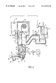
- FIG. 1 shows a metallurgic vessel with a bottom passage orifice
- FIG. 2 shows a metallurgic vessel with a gaseous or liquid media feed
- FIG. 3 shows a metallurgic vessel with a feed of solid media
- FIG. 4 shows a diagrammatic profile of the local liquidus and solidus temperatures.
- a carrier strip 21 is led through a bottom passage 13 of a metallurgic vessel 11 into a melt S. Beneath the bottom of the metallurgic vessel 11 is provided a housing 61 , in which a preheating device 41 is arranged. A media feed 51 connected to a media supply 52 is introduced into housing 61 .
- the carrier strip 21 is led via a pair of feed rollers 31 through housing 61 and the bottom passage 13 into the metallurgic vessel 11 , and the coated carrier strip 22 is conveyed out of the metallurgic vessel 11 and discharged via a pair of discharge rollers 32 provided at the exit 12 of the metallurgic vessel 11 .
- the metallurgic vessel of FIG. 1 may also be designed differently, for example as a dip vessel, into which the carrier strip is introduced from above and, after being deflected around a roller arranged in the melting bath, is discharged in an upward direction.
- FIG. 2 shows a media feed 51 for gaseous or liquid media which, coming from the media supply 52 , are capable of being introduced into the housing 61 with the aid of a media conveyor 54 .
- Blow nozzles 53 are employed when gaseous media are used and spray nozzles 55 in the case of liquid media.
- the preheating device provided is a burner 43 which may be arranged downstream of the spray or blow nozzles 53 , 55 (right side of the diagram) or upstream of these (left side of the diagram) in the strip conveying direction.
- FIG. 2 indicates, at 82 , a sandblaster, by means of which the blasting medium is administered to the surface of the carrier strip via blast nozzles 84 .
- the blasting medium is extracted from the container 85 and is conveyed via a pump 86 .
- the melt S is added with a low degree of flow to the metallurgic vessel in the region of the bottom, a vacuum distributor 77 being used which is connected to a vacuum pump 78 .
- melt is led into a receiving vessel 76 of the vacuum distributor 77 through an immersion-type casting spout 73 .
- FIG. 2 illustrates diagrammatically, as a measuring and regulating device, a processor 94 which is connected to temperature measuring elements 91 for detecting the melt temperature, to temperature measuring elements 92 for detecting the temperature of the carrier strip 21 and to measuring elements for detecting the speed 93 and for detecting the bath height 97 .
- the processor 94 acts via actuators 95 on the strip speed and via an actuator 96 on the plug 74 and therefore essentially on the bath height of the melt S located in the metallurgic vessel 11 .
- FIG. 3 shows a further metallurgic vessel 11 with a bottom passage 13 through which a carrier strip 21 is led.
- a housing 61 Outside the bottom region of the metallurgic vessel 11 is arranged a housing 61 , in which a preheating device in the form of a burner 43 or of an inductive heating system 42 is arranged.
- the interior 62 of the housing 61 is connected via a media feed 51 to a media supply 52 . 1 for gaseous media.
- solid bodies B On the left of the carrier strip 21 are solid bodies B, which are capable of being pressed against the surface of the carrier strip 21 by a media supply 52 . 2 .
- the strip 21 prior to entering the housing 61 can pass through a roughening device 81 which may be in the form of brushes 83 .
- the upper orifice 12 of the metallurgic vessel 11 is covered by the hood 63 which is connected to an inert gas supply 58 .
- the hood 63 has dimensions which cover the transport path of the coated carrier strip 22 over a predeterminable distance.
- a roll stand 33 by means of which hot forming can be carried out, is indicated diagrammatically outside the hood 63 .
- the material feed in FIG. 3 is carried out via a ladle 71 .
- the ladle 71 has a bottom orifice 72 , at which is arranged an immersion-type casting spout 73 which is capable of being closed by means of a slide 75 and which penetrates into the melt S.
Landscapes
- Chemical & Material Sciences (AREA)
- Chemical Kinetics & Catalysis (AREA)
- Engineering & Computer Science (AREA)
- Materials Engineering (AREA)
- Mechanical Engineering (AREA)
- Metallurgy (AREA)
- Organic Chemistry (AREA)
- Coating With Molten Metal (AREA)
- Continuous Casting (AREA)
- Manufacture Of Alloys Or Alloy Compounds (AREA)
Applications Claiming Priority (3)
| Application Number | Priority Date | Filing Date | Title |
|---|---|---|---|
| DE19758140A DE19758140A1 (de) | 1997-12-19 | 1997-12-19 | Verfahren zum Erzeugen von Metallprodukten aus Verbundwerkstoff |
| DE19758140 | 1997-12-19 | ||
| PCT/DE1998/003764 WO1999032683A1 (de) | 1997-12-19 | 1998-12-15 | Verfahren zur herstellung eines bandförmigen metallischen verbundwerkstoffes durch hochtemperatur-tauchbeschichten |
Publications (1)
| Publication Number | Publication Date |
|---|---|
| US6436556B1 true US6436556B1 (en) | 2002-08-20 |
Family
ID=7853538
Family Applications (1)
| Application Number | Title | Priority Date | Filing Date |
|---|---|---|---|
| US09/581,888 Expired - Fee Related US6436556B1 (en) | 1997-12-19 | 1998-12-15 | Method for producing a strip-like metal composite by high temperature dip coating |
Country Status (11)
| Country | Link |
|---|---|
| US (1) | US6436556B1 (de) |
| EP (1) | EP1042525B1 (de) |
| JP (1) | JP2001527157A (de) |
| KR (1) | KR20010024760A (de) |
| CN (1) | CN1189586C (de) |
| AT (1) | ATE262048T1 (de) |
| AU (1) | AU735907B2 (de) |
| BR (1) | BR9814297A (de) |
| CA (1) | CA2315797A1 (de) |
| DE (2) | DE19758140A1 (de) |
| WO (1) | WO1999032683A1 (de) |
Cited By (4)
| Publication number | Priority date | Publication date | Assignee | Title |
|---|---|---|---|---|
| US20040163589A1 (en) * | 2002-08-28 | 2004-08-26 | Amtec Kistler Gmbh | Device for applying a coating agent |
| US20060153992A1 (en) * | 2002-11-21 | 2006-07-13 | Bernhard Tenckhoff | Method and device for hot-dip coating a metal bar |
| US20170096348A1 (en) * | 2014-06-06 | 2017-04-06 | National Institute Of Advanced Industrial Science And Technology | Ammonia adsorbent |
| US11018270B2 (en) * | 2018-03-08 | 2021-05-25 | Lg Electronics Inc. | Flux coating device and method for solar cell panel, and apparatus for attaching interconnector of solar cell panel |
Citations (13)
| Publication number | Priority date | Publication date | Assignee | Title |
|---|---|---|---|---|
| US1552041A (en) * | 1924-05-09 | 1925-09-01 | Frederick M Crapo | Protected metal and process of making it |
| US1726652A (en) * | 1925-03-25 | 1929-09-03 | Indiana Steel & Wire Company | Process of making protected metal |
| GB422512A (en) * | 1934-01-24 | 1935-01-14 | Rylands Brothers Ltd | Improvements in or relating to methods and apparatus for galvanising or zinc coatingiron or steel articles |
| GB424373A (en) * | 1934-01-24 | 1935-02-20 | Rylands Brothers Ltd | Improvements in or relating to methods and apparatus for galvanizing or zinc coating iron or steel articles |
| GB929262A (en) * | 1962-03-05 | 1963-06-19 | Inland Steel Co | Aluminizing of ferrous metal base |
| US3483030A (en) * | 1966-12-19 | 1969-12-09 | Texas Instruments Inc | Chill cladding method and apparatus |
| GB1396419A (en) * | 1972-08-17 | 1975-06-04 | Gkn South Wales Ltd | Hot-dip zinc galvanizing of ferrous articles |
| JPS53127333A (en) * | 1977-04-13 | 1978-11-07 | Nippon Steel Corp | Manufacture of zero spangle galvanized steel sheet |
| JPS58110665A (ja) * | 1981-12-22 | 1983-07-01 | Sumitomo Metal Ind Ltd | 溶融亜鉛メツキ鋼板の製造方法 |
| JPS61166986A (ja) * | 1985-01-17 | 1986-07-28 | Masami Kobayashi | 金属メツキを施したアモルフアス合金 |
| DE3835393A1 (de) * | 1988-03-14 | 1989-09-28 | Metalleichtbau Veb K | Verfahren zur chemischen behandlung von metallteilen |
| FR2661426A1 (fr) * | 1990-04-27 | 1991-10-31 | Maubeuge Fer | Procede de galvanisation au trempe et en continu. |
| WO1997021846A1 (fr) * | 1995-12-14 | 1997-06-19 | Sollac | Procede de galvanisation de tole d'acier contenant des elements d'addition oxydables |
Family Cites Families (10)
| Publication number | Priority date | Publication date | Assignee | Title |
|---|---|---|---|---|
| US2444422A (en) * | 1942-09-07 | 1948-07-06 | Specialties Dev Corp | Producing aluminum-coated iron or steel |
| US2898251A (en) * | 1956-11-19 | 1959-08-04 | Jones & Laughlin Steel Corp | Aluminum coated steel article and method of producing it |
| JPS5672161A (en) * | 1979-11-19 | 1981-06-16 | Meidensha Electric Mfg Co Ltd | Plating method on nitrided article |
| JPS57108253A (en) * | 1980-12-24 | 1982-07-06 | Kawasaki Steel Corp | Production of zinc plated steel plate having differential thickness |
| JPS58174564A (ja) * | 1982-04-07 | 1983-10-13 | Kawatetsu Kohan Kk | 鋼帯のアルミニウムあるいはアルミニウム亜鉛合金メツキ方法 |
| JPS60194053A (ja) * | 1984-03-15 | 1985-10-02 | Sumitomo Metal Ind Ltd | 溶融亜鉛メツキ鋼板の製造方法 |
| JPH0397839A (ja) * | 1989-09-11 | 1991-04-23 | Fujitsu Ltd | 複合軽量防振材とその製法 |
| JPH05112858A (ja) * | 1991-10-21 | 1993-05-07 | Kobe Steel Ltd | 耐2次加工脆性又は焼付け硬化性に優れた高r値溶融亜鉛メツキ冷延鋼板の製造方法 |
| JP3301044B2 (ja) * | 1993-04-26 | 2002-07-15 | 株式会社ヨドキャスチング | 鋳鉄製マンホール蓋のめっき方法 |
| JP3894635B2 (ja) * | 1997-08-11 | 2007-03-22 | 株式会社小松製作所 | 浸炭部材とその製造方法並びに浸炭処理システム |
-
1997
- 1997-12-19 DE DE19758140A patent/DE19758140A1/de not_active Ceased
-
1998
- 1998-12-15 CN CNB988123126A patent/CN1189586C/zh not_active Expired - Fee Related
- 1998-12-15 AT AT98966569T patent/ATE262048T1/de not_active IP Right Cessation
- 1998-12-15 DE DE59811020T patent/DE59811020D1/de not_active Expired - Fee Related
- 1998-12-15 JP JP2000525596A patent/JP2001527157A/ja active Pending
- 1998-12-15 CA CA002315797A patent/CA2315797A1/en not_active Abandoned
- 1998-12-15 EP EP98966569A patent/EP1042525B1/de not_active Expired - Lifetime
- 1998-12-15 KR KR1020007006680A patent/KR20010024760A/ko not_active Withdrawn
- 1998-12-15 BR BR9814297-6A patent/BR9814297A/pt not_active IP Right Cessation
- 1998-12-15 WO PCT/DE1998/003764 patent/WO1999032683A1/de not_active Ceased
- 1998-12-15 US US09/581,888 patent/US6436556B1/en not_active Expired - Fee Related
- 1998-12-15 AU AU24103/99A patent/AU735907B2/en not_active Ceased
Patent Citations (13)
| Publication number | Priority date | Publication date | Assignee | Title |
|---|---|---|---|---|
| US1552041A (en) * | 1924-05-09 | 1925-09-01 | Frederick M Crapo | Protected metal and process of making it |
| US1726652A (en) * | 1925-03-25 | 1929-09-03 | Indiana Steel & Wire Company | Process of making protected metal |
| GB422512A (en) * | 1934-01-24 | 1935-01-14 | Rylands Brothers Ltd | Improvements in or relating to methods and apparatus for galvanising or zinc coatingiron or steel articles |
| GB424373A (en) * | 1934-01-24 | 1935-02-20 | Rylands Brothers Ltd | Improvements in or relating to methods and apparatus for galvanizing or zinc coating iron or steel articles |
| GB929262A (en) * | 1962-03-05 | 1963-06-19 | Inland Steel Co | Aluminizing of ferrous metal base |
| US3483030A (en) * | 1966-12-19 | 1969-12-09 | Texas Instruments Inc | Chill cladding method and apparatus |
| GB1396419A (en) * | 1972-08-17 | 1975-06-04 | Gkn South Wales Ltd | Hot-dip zinc galvanizing of ferrous articles |
| JPS53127333A (en) * | 1977-04-13 | 1978-11-07 | Nippon Steel Corp | Manufacture of zero spangle galvanized steel sheet |
| JPS58110665A (ja) * | 1981-12-22 | 1983-07-01 | Sumitomo Metal Ind Ltd | 溶融亜鉛メツキ鋼板の製造方法 |
| JPS61166986A (ja) * | 1985-01-17 | 1986-07-28 | Masami Kobayashi | 金属メツキを施したアモルフアス合金 |
| DE3835393A1 (de) * | 1988-03-14 | 1989-09-28 | Metalleichtbau Veb K | Verfahren zur chemischen behandlung von metallteilen |
| FR2661426A1 (fr) * | 1990-04-27 | 1991-10-31 | Maubeuge Fer | Procede de galvanisation au trempe et en continu. |
| WO1997021846A1 (fr) * | 1995-12-14 | 1997-06-19 | Sollac | Procede de galvanisation de tole d'acier contenant des elements d'addition oxydables |
Cited By (6)
| Publication number | Priority date | Publication date | Assignee | Title |
|---|---|---|---|---|
| US20040163589A1 (en) * | 2002-08-28 | 2004-08-26 | Amtec Kistler Gmbh | Device for applying a coating agent |
| US7018476B2 (en) * | 2002-08-28 | 2006-03-28 | Amtec Kistler Gmbh | Device for applying a coating agent |
| US20060153992A1 (en) * | 2002-11-21 | 2006-07-13 | Bernhard Tenckhoff | Method and device for hot-dip coating a metal bar |
| US20170096348A1 (en) * | 2014-06-06 | 2017-04-06 | National Institute Of Advanced Industrial Science And Technology | Ammonia adsorbent |
| US10647593B2 (en) * | 2014-06-06 | 2020-05-12 | National Institute Of Advanced Industrial Science And Technology | Ammonia adsorbent |
| US11018270B2 (en) * | 2018-03-08 | 2021-05-25 | Lg Electronics Inc. | Flux coating device and method for solar cell panel, and apparatus for attaching interconnector of solar cell panel |
Also Published As
| Publication number | Publication date |
|---|---|
| WO1999032683A1 (de) | 1999-07-01 |
| JP2001527157A (ja) | 2001-12-25 |
| EP1042525B1 (de) | 2004-03-17 |
| KR20010024760A (ko) | 2001-03-26 |
| ATE262048T1 (de) | 2004-04-15 |
| CN1282382A (zh) | 2001-01-31 |
| EP1042525A1 (de) | 2000-10-11 |
| DE59811020D1 (de) | 2004-04-22 |
| BR9814297A (pt) | 2000-10-03 |
| DE19758140A1 (de) | 1999-07-08 |
| CN1189586C (zh) | 2005-02-16 |
| AU2410399A (en) | 1999-07-12 |
| CA2315797A1 (en) | 1999-07-01 |
| AU735907B2 (en) | 2001-07-19 |
Similar Documents
| Publication | Publication Date | Title |
|---|---|---|
| CA1102186A (en) | Process of hot-dip galvanizing and alloying | |
| EP0172030B1 (de) | Aufbringen von Überzügen durch Aufsprühen von geschmolzenen Metallen | |
| JPH0130904B2 (de) | ||
| US6436556B1 (en) | Method for producing a strip-like metal composite by high temperature dip coating | |
| EP0545408B1 (de) | Meniskusüberziehung eines Stahlbleches | |
| US5226953A (en) | Process and device for producing a laminated material for slide elements | |
| KR100290446B1 (ko) | 압연물을 다층 코팅하기 위한 방법 및 장치 | |
| AU707850B2 (en) | Process and device for producing metallic composite materials | |
| JPS60159162A (ja) | 金属の噴霧沈着法 | |
| US4207831A (en) | Apparatus for one side coating of a continuous strip | |
| PL81125B1 (en) | Method of producing a coated ferrous substrate[gb1269150a] | |
| US5148855A (en) | Feeding system for belt casting of molten metal | |
| US5451429A (en) | Method and apparatus for treating freshly metallized substrates | |
| US4973500A (en) | Method of plating metal sheets by passing the sheet upwards in close proximity to an upwardly directed nozzle | |
| JPH07113154A (ja) | 溶融金属めっき方法及び装置 | |
| US4288476A (en) | One side coating of continuous strand | |
| JPH05311388A (ja) | 金属板の連続溶融金属めっき方法及びその装置 | |
| RU2358033C1 (ru) | Способ и устройство для нанесения покрытия на металлическую полосу погружением в расплав | |
| EP0124688A1 (de) | Giessen unter einer Atmosphäre geringer Dichte | |
| JPS6048586B2 (ja) | 両面溶融亜鉛めつき装置 | |
| Flinchum et al. | Meniscus Coating Steel Strip | |
| JPS60145368A (ja) | 溶融金属めつきの表面改質方法 | |
| WO1999055469A1 (en) | Metal spray-coated flat-rolled mild steel and its manufacture | |
| PL123261B1 (de) | ||
| Iida et al. | Automatic controller of alloying degree in galvannealing of steel sheet |
Legal Events
| Date | Code | Title | Description |
|---|---|---|---|
| AS | Assignment |
Owner name: SMS DEMAG AG, GERMANY Free format text: ASSIGNMENT OF ASSIGNORS INTEREST;ASSIGNORS:BLECK, WOLFGANG;BUNTEN, ROLF;FRIEDEL, FRANK;AND OTHERS;REEL/FRAME:011158/0816;SIGNING DATES FROM 20000615 TO 20000720 Owner name: THYSSEN KRUPP STAHL AG, GERMANY Free format text: ASSIGNMENT OF ASSIGNORS INTEREST;ASSIGNORS:BLECK, WOLFGANG;BUNTEN, ROLF;FRIEDEL, FRANK;AND OTHERS;REEL/FRAME:011158/0816;SIGNING DATES FROM 20000615 TO 20000720 |
|
| FPAY | Fee payment |
Year of fee payment: 4 |
|
| REMI | Maintenance fee reminder mailed | ||
| LAPS | Lapse for failure to pay maintenance fees | ||
| STCH | Information on status: patent discontinuation |
Free format text: PATENT EXPIRED DUE TO NONPAYMENT OF MAINTENANCE FEES UNDER 37 CFR 1.362 |
|
| FP | Lapsed due to failure to pay maintenance fee |
Effective date: 20100820 |