US6763928B2 - Bottle alignment apparatus - Google Patents
Bottle alignment apparatus Download PDFInfo
- Publication number
- US6763928B2 US6763928B2 US10/221,015 US22101502A US6763928B2 US 6763928 B2 US6763928 B2 US 6763928B2 US 22101502 A US22101502 A US 22101502A US 6763928 B2 US6763928 B2 US 6763928B2
- Authority
- US
- United States
- Prior art keywords
- cups
- hollow bodies
- comb
- members
- manner
- Prior art date
- Legal status (The legal status is an assumption and is not a legal conclusion. Google has not performed a legal analysis and makes no representation as to the accuracy of the status listed.)
- Expired - Lifetime
Links
Images


Classifications
-
- B—PERFORMING OPERATIONS; TRANSPORTING
- B65—CONVEYING; PACKING; STORING; HANDLING THIN OR FILAMENTARY MATERIAL
- B65G—TRANSPORT OR STORAGE DEVICES, e.g. CONVEYORS FOR LOADING OR TIPPING, SHOP CONVEYOR SYSTEMS OR PNEUMATIC TUBE CONVEYORS
- B65G47/00—Article or material-handling devices associated with conveyors; Methods employing such devices
- B65G47/22—Devices influencing the relative position or the attitude of articles during transit by conveyors
- B65G47/24—Devices influencing the relative position or the attitude of articles during transit by conveyors orientating the articles
- B65G47/244—Devices influencing the relative position or the attitude of articles during transit by conveyors orientating the articles by turning them about an axis substantially perpendicular to the conveying plane
-
- B—PERFORMING OPERATIONS; TRANSPORTING
- B29—WORKING OF PLASTICS; WORKING OF SUBSTANCES IN A PLASTIC STATE IN GENERAL
- B29C—SHAPING OR JOINING OF PLASTICS; SHAPING OF MATERIAL IN A PLASTIC STATE, NOT OTHERWISE PROVIDED FOR; AFTER-TREATMENT OF THE SHAPED PRODUCTS, e.g. REPAIRING
- B29C49/00—Blow-moulding, i.e. blowing a preform or parison to a desired shape within a mould; Apparatus therefor
- B29C49/42—Component parts, details or accessories; Auxiliary operations
- B29C49/4205—Handling means, e.g. transfer, loading or discharging means
- B29C49/42069—Means explicitly adapted for transporting blown article
Definitions
- the present invention refers to a high-productivity apparatus for the orientation at a very fast rate of hollow plastic articles, in particular bottles, which have not a circular form, but have instead their body in the shape of a parallelepiped with a rectangular cross-section.
- the present invention applies in a preferred manner to the working steps that follow a phase of simultaneous blow moulding of a plurality of bottles with a rectangular cross-section.
- the present invention applies to that section of a plant and that process that are solely used to blow mould, and therefore convert into a finished product, a previously produced preform, regardless of whether such a section belongs to a single-step plant or a double-step one.
- bottles intended for use in the most varied applications use is increasingly being made of a particular kind of bottle, i.e. bottles whose body is in the shape of a parallelepiped having a horizontal cross-section, with respect to the resting plane of the bottle, in the shape of a rectangle.
- the above cited bottles are brought into a side-by-side arrangement, as illustrated in FIG. 1, and they are all oriented in such a manner as to ensure that the pairs of opposite walls of each bottle are either parallel or orthogonal to the plane passing through all axes of the bottles.
- the second drawback relates to the size of the blow moulding plant. Looking again at FIG. 1, it can quite easily be inferred that, if the bottles are in a rather large number and their major side is rather wide, then, owing to these bottles having to be brought into a side-by-side arrangement, they impose a correspondingly large size on the blow-moulding mould, with further problems as far as tightness, strength, rigidity, and control of the handling organs are among other things of concern, as those skilled in the art are well aware of.
- the present invention may take the form of a preferred, although not sole embodiment such as the one that is described in detail and illustrated below by way of non-limiting example with reference to the accompanying drawings, in which:
- FIG. 1 is a top view of a blow moulding plan
- FIG. 2 is a symbolical side view of a blow moulding plant
- FIG. 3 is a top view of the blow moulding dies in their open state and the arrangement of the bottles according to a modality considered by the present invention
- FIGS. 4 a and 4 b are a perspective view and a cross-sectional view, respectively, of a component part of a plant according to the present invention
- FIGS. 5 a and 5 b are views corresponding to those illustrated in FIGS. 4 a and 4 b , with the same component part viewed from an orthogonal position on the horizontal plane;
- FIGS. 6 a and 6 b are views of two apparatuses of a plant according to the present invention in two distinct operating states thereof;
- FIGS. 7 a and 7 b are perspective and see-through views, respectively, of the mutual engagement of two apparatuses according to the present invention.
- FIG. 8 is a perspective view of a mode of mutual engagement of the apparatuses according to the present invention.
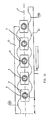
- FIGS. 9 and 10 are respective top views of a plant according to the present invention, which is shown deprived of some of its apparatuses (cups) to provide for better visibility of the structure;
- FIGS. 11 and 12 are views corresponding to the ones of FIGS. 9 and 10, however with the apparatuses (cups) regularly installed;
- FIGS. 13 and 14 are views from “A” of the illustrations in the respective FIGS. 11 and 12 .
- a prior-art blow moulding plant comprises a conveying line 21 for transferring a plurality of preforms 1 into a blow moulding die 2 .
- the bottles that have been just blow moulded and put into an alignment such as illustrated in FIG. 3, i.e. with their side walls oriented at an angle with respect to the plane “P” passing through the respective axes “X” centered in the respective mouth portions, are transferred to an alignment mechanism that is assigned the task of orienting all such bottles as illustrated symbolically in FIG. 1 , i.e. in such a manner as to ensure that the pairs of opposite walls of each bottle are either parallel or orthogonal to said plane “P”.
- the above cited mechanism substantially comprises a pair of mutually opposing, symmetrical comb-like members 10 , 11 and a plurality of identical cup-like members, hereinafter called simply “cups” 26 , which are adapted to be inserted in appropriate seats or housings between the comb-like members. This shall be explained in greater detail further on.
- each one of the comb-like members 10 , 11 is an elongated structure, while the side of each such comb-like member facing the opposite comb-like member is provided with a sequence of a plurality of plane surfaces 22 that are regularly spaced from each other by configurations 23 in the shape of an arc of a circle with a radius R equal to the inner radius of the cups.
- the plane surfaces and the configurations have the same overall size and the same distribution along the comb-like members, respectively, as can be clearly seen for instance from the illustrations in FIGS. 6 a and 9 .
- these comb-like members are symmetrical structures with respect to a plane of symmetry that, as this will be better explained further on, coincides with the plane “P” (see FIG. 6 a ).
- These comb-like members are adapted to be mutually displaced with respect to each other through a rectilinear translational movement until they move into the position illustrated in FIG. 6 b.
- the actual extent of a displacement “S” is such as to ensure that a particular configuration 24 provided in the comb-like member 10 , initially opposing a respective configuration 24 a provided in the comb-like member 11 , will find itself opposing exactly a configuration 25 a adjacent to the configuration 24 a on the same cup 26 after the displacement.
- FIGS. 4 a through to 5 b there are provided a plurality of identical cups 26 formed by a central cylindrical body 27 , a possible upward oriented flared portion 28 to better accommodate and center the related bottle therein, and a pair of symmetrical apertures 30 , 31 provided in mutually opposing positions on the same body 27 .
- each aperture has a height “h” in the direction of the axis of the cup, and a radial depth “r” measured in the radial direction starting from the outer wall of the cup.
- FIGS. 7 a , 7 b and 13 illustrate, including in a perspective view and a perspective see-through view, the kind of engagement between one of the cups 26 and one of the comb-like members 10 .
- the cup 26 is capable of being partially inserted in any of the configurations 23 ;
- the radius of the configurations is furthermore equal to the radius of the cup
- the height “H” of the comb-like member 10 is slightly smaller than the height “h” of the apertures on the outer surface of the cups, as has already been explained;
- the radial depth “r”, as defined above, is substantially similar to or slightly greater than the depth “R” of the configurations 23 with respect to the plane surfaces 22 .
- FIG. 8 which illustrates by way of example the application of a single cup
- a plurality of the cups 26 it is possible for a plurality of the cups 26 to be inserted in the seats or housings that are capable of being formed by the semi-circular configurations when they are arranged in front of each other in the respective comb-like members.
- the plurality of bottles 3 in the position they take at the moment of their insertion.
- the cups 26 which are anyway necessary, have been omitted for the sole purpose of more effectively showing the mutual position of bottles and comb-like members.
- FIG. 10 represents again the situation illustrated in FIG. 9, with the sole difference being that, in this case, the two comb-like members 10 and 11 are caused to translate so as to align the bottles as shown in the Figure. This will be described in greater detail further on.
- FIG. 12 represents again the situation illustrated in FIG. 11, with the sole difference that, in this case, the two comb-like members 10 and 11 are caused to translate so as to align the bottles as shown in the Figure. This will be described in greater detail further on.
- the bottles In a first phase the bottles, as released from the blow moulding dies and arranged as shown in FIG. 3, are picked up and inserted in the respective cups, usually with the use of known means that are adapted to at the same time transfer the bottles, while maintaining the mutual orientation and position thereof, as is shown in FIGS. 9 and 13.
- the assembly so formed by the bottles, the cups and the comb-like members is arranged as illustrated in FIG. 11 .
- the two comb-like members are caused to translate and displace relative to each other by a distance “S” so as to bring them from the position illustrated in FIG. 6 a to the position illustrated in FIG. 6 b .
- the corner 41 of the related configuration of the comb-like member 10 enters into contact with and pushes the side 42 of the respective bottle, and so on for the other bottles, in the sense that the corner 43 of the respective configuration of the comb-like member 10 enters into contact with and pushes the side 44 of the adjacent bottle, on which also the corner 45 acts on the opposite side against the side 46 thereof, and so on.
- the direct contact of the corners with the related bottles is enabled to occur by the afore mentioned circumstance that the size of the apertures 30 and 31 in the respective cups is such as to allow for the corners to penetrate into the cups and, as a result, to push the bottles and cause then to rotate without anyway causing the cups themselves to rotate.
- FIG. 10 The overall effect of such an operation is illustrated in FIG. 10, in which there is illustrated that, at the end of the displacement by a length “S” of the comb-like members 10 and 11 , the combined and symmetrical action of the corners of the configurations of both comb-like members causes the bottles to rotate synchronously until they move into the position of full alignment illustrated in FIG. 10, in which the cups have been omitted, and in FIG. 11 which on the contrary includes also the cups. Furthermore, the illustration in FIG. 14 may prove helpful in making still clearer the mutual position of the discussed component parts at the end of the phase of translational displacement (of the comb-like members) and resulting rotation of the bottles.
- the bottle alignment operation can be considered to be concluded and the bottles themselves may therefore be picked up by any appropriate known means to be sent, with the desired alignment, to the subsequent processing or production phases.
Landscapes
- Engineering & Computer Science (AREA)
- Mechanical Engineering (AREA)
- Manufacturing & Machinery (AREA)
- Blow-Moulding Or Thermoforming Of Plastics Or The Like (AREA)
- Containers Having Bodies Formed In One Piece (AREA)
- Filling Of Jars Or Cans And Processes For Cleaning And Sealing Jars (AREA)
- Attitude Control For Articles On Conveyors (AREA)
- Feeding, Discharge, Calcimining, Fusing, And Gas-Generation Devices (AREA)
- Feeding Of Articles To Conveyors (AREA)
- Details Of Rigid Or Semi-Rigid Containers (AREA)
- Wrapping Of Specific Fragile Articles (AREA)
Applications Claiming Priority (4)
| Application Number | Priority Date | Filing Date | Title |
|---|---|---|---|
| ITPN2000A000016 | 2000-03-09 | ||
| ITPN2000A0016 | 2000-03-09 | ||
| IT2000PN000016A ITPN20000016A1 (it) | 2000-03-09 | 2000-03-09 | Dispositivo per allineamento bottiglie |
| PCT/EP2001/001574 WO2001066445A1 (en) | 2000-03-09 | 2001-02-13 | Bottle alignment apparatus |
Publications (2)
| Publication Number | Publication Date |
|---|---|
| US20030113172A1 US20030113172A1 (en) | 2003-06-19 |
| US6763928B2 true US6763928B2 (en) | 2004-07-20 |
Family
ID=11453115
Family Applications (1)
| Application Number | Title | Priority Date | Filing Date |
|---|---|---|---|
| US10/221,015 Expired - Lifetime US6763928B2 (en) | 2000-03-09 | 2001-02-13 | Bottle alignment apparatus |
Country Status (9)
| Country | Link |
|---|---|
| US (1) | US6763928B2 (de) |
| EP (1) | EP1261537B1 (de) |
| CN (1) | CN1196638C (de) |
| AT (1) | ATE350312T1 (de) |
| AU (1) | AU2001250314A1 (de) |
| DE (1) | DE60125727T2 (de) |
| ES (1) | ES2278736T3 (de) |
| IT (1) | ITPN20000016A1 (de) |
| WO (1) | WO2001066445A1 (de) |
Cited By (5)
| Publication number | Priority date | Publication date | Assignee | Title |
|---|---|---|---|---|
| US20110314627A1 (en) * | 2010-06-24 | 2011-12-29 | Samsung Sdi Co., Ltd. | Apparatus for removing foreign materials on can of rechargeable battery |
| US20130180834A1 (en) * | 2012-01-16 | 2013-07-18 | Krones Aktiengesellschaft | Carrier element for articles or containers |
| US9403668B2 (en) | 2010-12-16 | 2016-08-02 | Krones, Ag | Device for processing containers with container alignment |
| USD1003725S1 (en) | 2021-09-03 | 2023-11-07 | Graham Packaging Company, L.P. | Container |
| USD1010454S1 (en) | 2021-09-03 | 2024-01-09 | Graham Packaging Company, L.P. | Container |
Families Citing this family (4)
| Publication number | Priority date | Publication date | Assignee | Title |
|---|---|---|---|---|
| US11135758B2 (en) * | 2013-02-18 | 2021-10-05 | Discma Ag | Machine and method for forming containers from preforms carried by successive moulds |
| DE102013215794A1 (de) | 2013-08-09 | 2015-02-12 | Krones Ag | Vorrichtung und Verfahren zum Ausrichten von unrunden Behältern |
| CN105417101B (zh) * | 2015-12-17 | 2017-09-12 | 北京大恒图像视觉有限公司 | 一种同步理瓶设备 |
| CN108928628A (zh) * | 2018-09-03 | 2018-12-04 | 王从银 | 一种用于水杯杯盖检测安装的输送装置 |
Citations (11)
| Publication number | Priority date | Publication date | Assignee | Title |
|---|---|---|---|---|
| US2723743A (en) * | 1951-05-16 | 1955-11-15 | Meyer Geo J Mfg Co | Labeling machine having means for orienting an article through a predetermined angle |
| GB1206363A (en) | 1967-02-01 | 1970-09-23 | Midland Ross Corp | Apparatus for removing mold flash |
| DE2427818A1 (de) | 1974-06-08 | 1976-01-02 | Hermann Dr Datz | Vorrichtung zum verkantungsfreien zufuehren von mittels automatischer kastenauspacker erfassten formflaschen an ein flaschentransportband |
| US4304543A (en) | 1972-04-19 | 1981-12-08 | Kautex-Werke Reinold Hagen Gmbh | Apparatus for the manufacture of hollow bodies |
| US4561534A (en) * | 1984-10-05 | 1985-12-31 | John R. Nalbach Engineering Co., Inc. | Container orienting apparatus |
| EP0589383A1 (de) | 1992-09-23 | 1994-03-30 | Husky Injection Molding Systems Ltd. | Station zum Entfernen von hohlen Gegenständen |
| US5484052A (en) * | 1994-05-06 | 1996-01-16 | Dowbrands L.P. | Carrier puck |
| US5701726A (en) * | 1997-01-24 | 1997-12-30 | Brenton Engineering Co. | Packaging apparatus for non-round containers |
| US5769203A (en) * | 1994-11-09 | 1998-06-23 | Marti Sala; Jaime | Automated facility for the unscrambling of light, hollow, elongated articles and for the lined up delivery of said articles |
| US6068110A (en) * | 1996-09-06 | 2000-05-30 | Matsushita Electric Industrial Co., Ltd. | Holder for cylindrical cell in conveyor system |
| US6176369B1 (en) * | 1998-10-08 | 2001-01-23 | Gebo Conveyors, Consultants & Systems, Inc. | Steerable carrier puck |
-
2000
- 2000-03-09 IT IT2000PN000016A patent/ITPN20000016A1/it unknown
-
2001
- 2001-02-13 ES ES01923569T patent/ES2278736T3/es not_active Expired - Lifetime
- 2001-02-13 AT AT01923569T patent/ATE350312T1/de not_active IP Right Cessation
- 2001-02-13 DE DE60125727T patent/DE60125727T2/de not_active Expired - Lifetime
- 2001-02-13 WO PCT/EP2001/001574 patent/WO2001066445A1/en not_active Ceased
- 2001-02-13 US US10/221,015 patent/US6763928B2/en not_active Expired - Lifetime
- 2001-02-13 EP EP01923569A patent/EP1261537B1/de not_active Expired - Lifetime
- 2001-02-13 AU AU2001250314A patent/AU2001250314A1/en not_active Abandoned
- 2001-02-13 CN CN01806122.2A patent/CN1196638C/zh not_active Expired - Fee Related
Patent Citations (11)
| Publication number | Priority date | Publication date | Assignee | Title |
|---|---|---|---|---|
| US2723743A (en) * | 1951-05-16 | 1955-11-15 | Meyer Geo J Mfg Co | Labeling machine having means for orienting an article through a predetermined angle |
| GB1206363A (en) | 1967-02-01 | 1970-09-23 | Midland Ross Corp | Apparatus for removing mold flash |
| US4304543A (en) | 1972-04-19 | 1981-12-08 | Kautex-Werke Reinold Hagen Gmbh | Apparatus for the manufacture of hollow bodies |
| DE2427818A1 (de) | 1974-06-08 | 1976-01-02 | Hermann Dr Datz | Vorrichtung zum verkantungsfreien zufuehren von mittels automatischer kastenauspacker erfassten formflaschen an ein flaschentransportband |
| US4561534A (en) * | 1984-10-05 | 1985-12-31 | John R. Nalbach Engineering Co., Inc. | Container orienting apparatus |
| EP0589383A1 (de) | 1992-09-23 | 1994-03-30 | Husky Injection Molding Systems Ltd. | Station zum Entfernen von hohlen Gegenständen |
| US5484052A (en) * | 1994-05-06 | 1996-01-16 | Dowbrands L.P. | Carrier puck |
| US5769203A (en) * | 1994-11-09 | 1998-06-23 | Marti Sala; Jaime | Automated facility for the unscrambling of light, hollow, elongated articles and for the lined up delivery of said articles |
| US6068110A (en) * | 1996-09-06 | 2000-05-30 | Matsushita Electric Industrial Co., Ltd. | Holder for cylindrical cell in conveyor system |
| US5701726A (en) * | 1997-01-24 | 1997-12-30 | Brenton Engineering Co. | Packaging apparatus for non-round containers |
| US6176369B1 (en) * | 1998-10-08 | 2001-01-23 | Gebo Conveyors, Consultants & Systems, Inc. | Steerable carrier puck |
Cited By (6)
| Publication number | Priority date | Publication date | Assignee | Title |
|---|---|---|---|---|
| US20110314627A1 (en) * | 2010-06-24 | 2011-12-29 | Samsung Sdi Co., Ltd. | Apparatus for removing foreign materials on can of rechargeable battery |
| US9403668B2 (en) | 2010-12-16 | 2016-08-02 | Krones, Ag | Device for processing containers with container alignment |
| US20130180834A1 (en) * | 2012-01-16 | 2013-07-18 | Krones Aktiengesellschaft | Carrier element for articles or containers |
| US8973745B2 (en) * | 2012-01-16 | 2015-03-10 | Krones Aktiengesellschaft | Carrier element for articles or containers |
| USD1003725S1 (en) | 2021-09-03 | 2023-11-07 | Graham Packaging Company, L.P. | Container |
| USD1010454S1 (en) | 2021-09-03 | 2024-01-09 | Graham Packaging Company, L.P. | Container |
Also Published As
| Publication number | Publication date |
|---|---|
| US20030113172A1 (en) | 2003-06-19 |
| DE60125727T2 (de) | 2007-11-08 |
| ATE350312T1 (de) | 2007-01-15 |
| DE60125727D1 (de) | 2007-02-15 |
| EP1261537B1 (de) | 2007-01-03 |
| CN1411418A (zh) | 2003-04-16 |
| ES2278736T3 (es) | 2007-08-16 |
| EP1261537A1 (de) | 2002-12-04 |
| ITPN20000016A1 (it) | 2001-09-09 |
| AU2001250314A1 (en) | 2001-09-17 |
| CN1196638C (zh) | 2005-04-13 |
| WO2001066445A1 (en) | 2001-09-13 |
Similar Documents
| Publication | Publication Date | Title |
|---|---|---|
| US6763928B2 (en) | Bottle alignment apparatus | |
| US5653934A (en) | Molded part take-out apparatus | |
| EP2769826B1 (de) | Freisetzungsvorrichtung für formteil und blasformvorrichtung | |
| EP0167660B1 (de) | Verfahren zum Spritzblasformen | |
| EP1458539B1 (de) | Vorrichtung und verfahren zum pressformen von kunststoff-artikeln | |
| AU775749B2 (en) | Rotary stretch blow moulding machine comprising a magnetically controlled stretch rod | |
| EP0873840A1 (de) | Spritzgiessmaschine zur Herstellung von Hohlkörpern aus Kunststoff | |
| US4299371A (en) | Neck ring assembly | |
| KR100694387B1 (ko) | 얇은 벽을 갖춘 물체를 형성하는 장치 | |
| RU2317202C2 (ru) | Устройство и способ для формования изделия с участком уменьшенного поперечного сечения | |
| RU2471625C1 (ru) | Пресс-форма для формования емкости, полученной из пластмассовой заготовки, и способ ее формования | |
| US20010038866A1 (en) | Machine for the production of preforms for hollow plastic containers | |
| EP0229845B1 (de) | Einspritzgiessvorrichtung | |
| RU2240230C2 (ru) | Устройство и способ транспортировки и охлаждения преформ | |
| JP3743829B2 (ja) | プリフォームの保持装置 | |
| US9950943B2 (en) | Neck ring system and glassware forming process | |
| WO2014192854A1 (ja) | 把手付き容器の成形装置、搬送治具及び容器用把手 | |
| CA1234549A (en) | Blow molding pallet assembly | |
| JPH09164555A (ja) | 射出成形品組立方法及び装置 | |
| JPH06722U (ja) | 自動型締機構付金型 | |
| SU1073111A1 (ru) | Литьева форма дл изготовлени полимерных изделий с арматурой | |
| WO2002092323A1 (en) | Method and machine for blowing plastic bottles | |
| JPH0214119A (ja) | 薄肉中空成形品への二次射出成形方法 |
Legal Events
| Date | Code | Title | Description |
|---|---|---|---|
| AS | Assignment |
Owner name: SIPA S.P.A., ITALY Free format text: ASSIGNMENT OF ASSIGNORS INTEREST;ASSIGNORS:GIROTTO, LUIGI;ZOPPAS, MATTEO;REEL/FRAME:014326/0420 Effective date: 20020913 |
|
| STCF | Information on status: patent grant |
Free format text: PATENTED CASE |
|
| FPAY | Fee payment |
Year of fee payment: 4 |
|
| FEPP | Fee payment procedure |
Free format text: PAYOR NUMBER ASSIGNED (ORIGINAL EVENT CODE: ASPN); ENTITY STATUS OF PATENT OWNER: LARGE ENTITY |
|
| FPAY | Fee payment |
Year of fee payment: 8 |
|
| FPAY | Fee payment |
Year of fee payment: 12 |
|
| SULP | Surcharge for late payment |
Year of fee payment: 11 |