US6845808B2 - Reduction casting method - Google Patents
Reduction casting method Download PDFInfo
- Publication number
- US6845808B2 US6845808B2 US10/384,718 US38471803A US6845808B2 US 6845808 B2 US6845808 B2 US 6845808B2 US 38471803 A US38471803 A US 38471803A US 6845808 B2 US6845808 B2 US 6845808B2
- Authority
- US
- United States
- Prior art keywords
- gas
- cavity
- molten metal
- magnesium
- casting method
- Prior art date
- Legal status (The legal status is an assumption and is not a legal conclusion. Google has not performed a legal analysis and makes no representation as to the accuracy of the status listed.)
- Expired - Lifetime, expires
Links
Images


Classifications
-
- B—PERFORMING OPERATIONS; TRANSPORTING
- B22—CASTING; POWDER METALLURGY
- B22D—CASTING OF METALS; CASTING OF OTHER SUBSTANCES BY THE SAME PROCESSES OR DEVICES
- B22D21/00—Casting non-ferrous metals or metallic compounds so far as their metallurgical properties are of importance for the casting procedure; Selection of compositions therefor
- B22D21/002—Castings of light metals
- B22D21/007—Castings of light metals with low melting point, e.g. Al 659 degrees C, Mg 650 degrees C
-
- B—PERFORMING OPERATIONS; TRANSPORTING
- B22—CASTING; POWDER METALLURGY
- B22D—CASTING OF METALS; CASTING OF OTHER SUBSTANCES BY THE SAME PROCESSES OR DEVICES
- B22D17/00—Pressure die casting or injection die casting, i.e. casting in which the metal is forced into a mould under high pressure
- B22D17/14—Machines with evacuated die cavity
-
- B—PERFORMING OPERATIONS; TRANSPORTING
- B22—CASTING; POWDER METALLURGY
- B22D—CASTING OF METALS; CASTING OF OTHER SUBSTANCES BY THE SAME PROCESSES OR DEVICES
- B22D27/00—Treating the metal in the mould while it is molten or ductile ; Pressure or vacuum casting
-
- B—PERFORMING OPERATIONS; TRANSPORTING
- B22—CASTING; POWDER METALLURGY
- B22D—CASTING OF METALS; CASTING OF OTHER SUBSTANCES BY THE SAME PROCESSES OR DEVICES
- B22D27/00—Treating the metal in the mould while it is molten or ductile ; Pressure or vacuum casting
- B22D27/18—Measures for using chemical processes for influencing the surface composition of castings, e.g. for increasing resistance to acid attack
Definitions
- the present invention relates to a reduction casting method. More particularly, the invention relates to a reduction casting method in which casting can be performed in a favorable state-without impairing reducing strength.
- GDC gravity casting method
- LPDC low pressure die casting method
- DC die casting method
- SC squeeze casting method
- a magnesium-nitrogen compound (Mg 3 N 2 ) having a strong reducing property is prepared by using a nitrogen gas and a magnesium gas and, then, the thus-prepared magnesium-nitrogen compound is allowed to act on the molten metal of aluminum, thereby performing casting.
- the magnesium gas is generated in a furnace and, when the magnesium gas is introduced into a cavity, an inert gas (argon gas) is used as a carrier gas.
- the nitrogen gas is directly introduced into the cavity in a separate manner.
- the oxide film formed on the surface of the molten metal is reduced by a reducing action of the magnesium-nitrogen compound to change the surface of the molten metal into pure aluminum, thereby decreasing a surface tension of the molten metal and, accordingly, enhancing a flowing property of the molten metal.
- a running property of the molten metal becomes advantageous whereupon a cast product which does not have a cast imperfection but has an excellent appearance deprived of a surface fold or the like can be obtained.
- the magnesium gas which is obtained by heat-subliming magnesium in the furnace is in a state of high temperature (about 800° C.).
- an object of the invention is to provide a reduction casting method which can performs casting in an advantageous state without impairing reducing strength.
- the invention has a constitution described below.
- a reduction casting method comprising the steps of:
- the flow quantity of the non-reactive gas is allowed to be from one fourth to one half the flow quantity of the reactive gas.
- the reactive gas, the non-reactive gas and the metallic gas are allowed to be a nitrogen gas, an argon gas and a magnesium gas, respectively.
- FIG. 1 is an explanatory diagram illustrating an example of a constitution of a casting apparatus which performs casting by a reduction casting method according to the present invention.
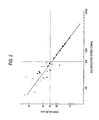
- FIG. 2 is a graph showing, in regard to an aluminum material, a measurement result as to how DASII value varies in accordance with a solidification speed of a molten metal.
- FIG. 1 is an explanatory diagram showing an entire constitution of a casting apparatus 10 for performing casting by utilizing a reduction casting method according to the invention. An application thereof for aluminum casting is illustrated below; however, the invention is by no means limited to the aluminum casting.
- reference numerals 11 and 12 denote a molding die and a cavity formed inside the molding die 11 , respectively.
- a sprue 14 shaped in a state of a tapered surface which becomes gradually smaller downward in diameter is provided.
- a plug 15 is detachably provided in the sprue 14 .
- a reference numeral 16 denotes a pipe which is vertically formed to pass through the plug 15 .
- a reference numeral 17 denotes a reservoir for containing the molten metal to be poured (hereinafter also referred to simply as “molten metal reservoir”) provided in the upper part of the molding die 11 .
- the molten metal reservoir 17 and the cavity 12 are communicated with each other via the sprue 14 .
- pouring of the molten metal into the cavity 12 is controlled.
- the molten metal of aluminum is stored in the molten metal reservoir 17 .
- the molding die 11 may be formed by using a material having favorable thermal conductivity. Further, the molding die 11 is provided with a cooling device with which it is forcibly cooled. In the embodiment, as the cooling device, a flow passage 13 is provided inside the molding die 11 such that cooling-water is allowed to constantly run through the flow passage 13 .
- a reason for forming the molding die 11 by using the material having favorable thermal conductivity and constantly forcibly cooling the molding die 11 is to hold a temperature thereof to be as low as possible. Therefore, so long as a cooling method is such that the temperature of the molding die 11 is effectively held to be low, the cooling method is not necessarily limited to such a water-cooling method as described above. It goes without saying that a plurality of cooling devices can simultaneously be used in combination.
- a reference numeral 20 denotes a steel cylinder 20 for containing a nitrogen gas (hereinafter also referred to “nitrogen gas-containing steel cylinder”).
- the nitrogen gas-containing steel cylinder 20 is connected to the molding die 11 via a piping system 22 in which a valve 24 is interposed and is arranged such that the nitrogen gas is allowed to be introduced into the cavity 12 through a nitrogen gas-introducing port 11 a provided in the molding die 11 .
- a valve 24 By opening the valve 24 to feed the nitrogen gas into the cavity 12 through the nitrogen gas-introducing port 11 a , air present in the cavity 12 is purged therefrom to produce a nitrogen gas atmosphere in the cavity 12 , so that a non-oxygen atmosphere is substantially produced in the cavity 12 .
- a reference numeral 11 b denotes an exhaust port provided in the molding die 11 . It is also possible that the non-oxygen atmosphere is produced in the cavity 12 by connecting a vacuum device to the exhaust port 11 b via the piping system in which a valve 25 is interposed and, then, operating the vacuum device in a state in which the valve 25 is opened.
- a reference numeral 21 denotes a steel cylinder for containing an argon gas (hereinafter also referred to as “argon gas-containing steel cylinder”).
- the argon gas-containing steel cylinder 21 is connected to a furnace 28 which is a generator for generating a metallic gas via a piping system 26 .
- a valve 30 which is interposed in the piping system 26 .
- pouring of the argon gas into the furnace 28 is controlled.
- the furnace 28 is heated by a heater 32 .
- a temperature in the furnace 28 is set to be a boiling point or less of magnesium, as well as a melting point or more of magnesium so that magnesium in the furnace 28 becomes in a liquid state.
- the argon gas-containing steel cylinder 21 is also connected to a tank 36 in which magnesium metal is contained via a piping system 34 in which a valve 33 is interposed; further, the tank 36 is connected to the piping system 26 in a downstream side of the valve 30 via a piping system 38 .
- a reference numeral 40 denotes a valve, which is interposed in the piping system 38 , for use in controlling a supply quantity of magnesium to the furnace 28 .
- the tank 36 is used for containing magnesium metal to be supplied to the furnace 28 , and the magnesium metal is contained therein in powder or granular form.
- the furnace 28 is connected to the cavity 12 of the molding die 11 via a piping system 42 and the pipe 16 which is attached to the plug 15 .
- Magnesium in gas or mist form which has been produced in the furnace 28 is introduced into the cavity 12 of the molding die 11 by performing an opening/closing operation of a valve 45 which is interposed in the piping system 42 and also controlling an argon gas pressure by the valve 30 .
- Aluminum casting by the casting apparatus 10 as shown in FIG. 1 is performed in a manner as described below.
- valve 24 is opened in a state in which the sprue 14 is closed by being fitted with the plug 15 to pour the nitrogen gas from the nitrogen gas-containing steel cylinder 20 into the cavity 12 of the molding die 11 via the piping system 22 .
- the nitrogen gas By such pouring of the nitrogen gas, air present inside the cavity 12 is purged therefrom, whereby a non-oxygen atmosphere is substantially produced in the cavity 12 and, then, the valve 24 is closed.
- the valve 30 is opened to pour the argon gas from the argon gas-containing steel cylinder 21 into the furnace 28 to produce a non-oxygen atmosphere in the furnace 28 .
- the valve 30 is closed and the valves 33 and 40 are opened to send the magnesium metal contained in the tank 36 into the furnace 28 by an argon gas pressure applied from the argon gas-containing steel cylinder 21 . Since the furnace 28 is heated at a temperature at which the magnesium metal is melt, the magnesium metal which has been sent in the furnace 28 turns to be in a molten state therein.
- magnesium gas Since the magnesium gas is sent out from the furnace 28 in a repeated manner every time a casting operation is performed, a certain quantity of magnesium metal which can corresponds to such operations is sent from the tank 36 to the furnace 28 . After the-magnesium metal is sent in the furnace 28 , valves 33 and 40 are closed.
- valves 30 and 45 are opened to pour the magnesium gas from the furnace 28 into the cavity 12 of the molding die 11 via the pipe 16 by using the argon gas as a carrier gas while controlling pressure and a flow quantity of the argon gas.
- magnesium in mist form is also sent out from the furnace 28 together with the magnesium gas.
- the valve 45 is closed and, then, the valve 24 is opened to pour the nitrogen gas into the cavity 12 through the nitrogen gas-introducing port 11 a .
- the magnesium gas previously poured in the cavity 12 and the thus-poured nitrogen gas are allowed to react with each other in the cavity 12 to produce the magnesium-nitrogen compound (Mg 3 N 2 ) which is a reducing compound.
- the magnesium-nitrogen compound is primarily deposited on a surface of an inner wall of the cavity 12 .
- the plug 15 is opened to pour the molten metal 18 from the sprue 14 into the cavity 12 .
- the molten metal 18 of aluminum thus poured in the cavity 12 comes into contact with the magnesium-nitrogen compound produced on the inner wall surface of the cavity 12 so that the magnesium-nitrogen compound deprives oxygen from an oxide film formed on a surface of the molten metal to reduce the surface of the molten metal, to pure aluminum which is, then, filled into the cavity 12 (reduction casting method).
- the magnesium-nitrogen compound deprives oxygen from an oxide film formed on a surface of the molten metal to reduce the surface of the molten metal, to pure aluminum which is, then, filled into the cavity 12 (reduction casting method).
- the molten metal 18 is filled into the cavity 12 in a short period of time, it is effective to cool the molten metal 18 which has been filled into the molding die 11 and solidify it in a short period of time.
- the molding die 18 is made of a material having a favorable thermal conductivity, so long as the temperature of the molding die 18 is held at a temperature or less at which the molding die 18 can have a sufficient hardness, for example, about 150° C. or less, casting can be performed by a casting method which uses the molding die made of such material, while preventing scoring from being generated in contact with the molten metal.
- the flow quantity of the argon gas (inert gas) which is supplied into the furnace 28 is measured by a flow meter provided together with the valve 30 . Further, the flow quantity of the nitrogen gas which is supplied into the cavity 12 is measured by a flow meter provided together with the valve 24 .
- the magnesium gas is introduced into the cavity 12 by being transported by the argon gas as a carrier gas.
- an inside of the furnace 28 is heated to 800° C. or more which is a temperature of subliming the magnesium.
- the cast product having a desired quality was able to be obtained by setting the flow quality of the argon gas to be one sixth to twice that of the nitrogen gas.
- the flow quantity of the argon gas was set to be one fourth to a half the flow quantity of the nitrogen gas.
- a solidification speed of the molten metal is set to be 600° C./minute or more (temperature decrease per unit time of the molten metal in the molding die 11 ) and preferably 800° C./minute or more. As the solidification speed is larger, a crystal structure of the cast product becomes denser; this feature is favorable since strength thereof is enhanced.
- This solidification speed is in neighborhood of that of a conventional DC.
- this reduction casting method does not rely on rapid cooling as is done in a splash or spraying filling of the DC but is capable of performing filling of the molten metal in a stratified or a partially turbulent state to allow an inner quality to be extremely favorable, a DASII value to be also small and expansion, strength and the like to be enhanced.
- FIG. 2 shows a result of measurement as to how a space between dendrites in a solidified body is changed when the solidification speed of the molten metal is changed in aluminum casting.
- the measurement was performed such that a portion of aluminum which has been filled into and solidified in the cavity 12 was taken out to be a sample and a space between dendrites thereof was measured by an electronic microscope.
- the solidification speed is shown in abscissa and the space between dendrites of solidified aluminum was shown in ordinate as “DASII value”.
- the space between the dendrites of aluminum relates to density of the solidified body (cast product) and, as the space between the dendrites becomes smaller, the crystal structure of aluminum becomes denser, so that mechanical strength of the cast product obtained is enhanced.
- the DASII value is 22 ⁇ m or less and preferably 20 ⁇ m or less.
- the term “the solidification speed of 600° C./minute or more (preferably 800° C./minute or more)” may be replaced by the term “the solidification speed at which the DASII value becomes 22 ⁇ m or less (preferably, the solidification speed at which the DASII value becomes 20 ⁇ m or less in the reduction casting method)”.
- the solidification speed is slow and, particularly in GDC or LPDC in which a heat-insulating coating agent is used, particularly slow, and thus, it is difficult to correspond to demixing, shrinkage hole and the like; therefore, there is a problem as to how directional cooling is performed.
- the solidification speed is about 100° C./min and, even in a thin wall part, is about 750° C./min and the DASII value to be described below was only in a level of from 35 ⁇ m to 20 ⁇ m.
- the filling time of the molten metal is determined depending on a relation between a material of a cast alloy and the solidification speed.
- the filling time of the molten metal becomes from 4.0 seconds to 1.2 second.
- the molten metal is applied with pressure by some device which is not limited to any particular type and all parts of the cavity 12 are filled with molten metal within a predetermined time in a same manner as in LPDC. For this reason, it is also important to appropriately select a diameter, a shape, a position, a number and the like of the sprue.
- the molten metal is allowed to be assuredly filled even into a fine part of the cavity 12 whereby cast imperfections to be caused by, for example, insufficient filling can be eliminated. Further, since the oxide film formed on the surface of the molten metal is removed, a surface fold or the like is not generated on the surface of the cast product whereby the cast product having an excellent appearance can be obtained.
- the magnesium gas, the nitrogen gas were directly introduced into the cavity to generate the magnesium-nitrogen compound; however, it is also permissible that a reaction chamber (not shown) is provided immediately in front of the molding die and, then, the argon gas, the magnesium gas and the nitrogen gas were introduced into the thus-provided reaction chamber to allow these gases to react thereamong in the reaction chamber and to generate the magnesium-nitrogen compound and, thereafter, the thus-generated magnesium-nitrogen compound is introduced into the cavity.
- the embodiment was explained with reference to the magnesium-nitrogen compound as the reducing substance of the molten metal, but a single body of magnesium or other reducing substances may also be used.
- the carrier gas other inert gases or non-oxidizing gases than the argon gas may also be used. These gases are collectively called herein as “non-reactive gas”.
- the solidification speed and the filling time of the molten metal are not limited to those described above.
- the method according to the invention is not limited thereto but is applicable to casting methods in which aluminum alloys, various types of metals such as magnesium and iron and alloys thereof are each used as a casting material.
- the flow quantity of the metallic gas can indirectly be controlled whereupon a remarkable effect can be exhibited such that the reduction casting can be performed in an advantageous manner without impairing the reducing strength.
Landscapes
- Engineering & Computer Science (AREA)
- Mechanical Engineering (AREA)
- Chemical & Material Sciences (AREA)
- Chemical Kinetics & Catalysis (AREA)
- General Chemical & Material Sciences (AREA)
- Molds, Cores, And Manufacturing Methods Thereof (AREA)
- Mold Materials And Core Materials (AREA)
- Manufacture Of Metal Powder And Suspensions Thereof (AREA)
- Continuous Casting (AREA)
Applications Claiming Priority (2)
| Application Number | Priority Date | Filing Date | Title |
|---|---|---|---|
| JPP.2002-068213 | 2002-03-13 | ||
| JP2002068213A JP3604375B2 (ja) | 2002-03-13 | 2002-03-13 | 還元鋳造方法 |
Publications (2)
| Publication Number | Publication Date |
|---|---|
| US20030217827A1 US20030217827A1 (en) | 2003-11-27 |
| US6845808B2 true US6845808B2 (en) | 2005-01-25 |
Family
ID=27764504
Family Applications (1)
| Application Number | Title | Priority Date | Filing Date |
|---|---|---|---|
| US10/384,718 Expired - Lifetime US6845808B2 (en) | 2002-03-13 | 2003-03-11 | Reduction casting method |
Country Status (6)
| Country | Link |
|---|---|
| US (1) | US6845808B2 (de) |
| EP (1) | EP1344590B1 (de) |
| JP (1) | JP3604375B2 (de) |
| CN (1) | CN100340362C (de) |
| BR (1) | BR0300557A (de) |
| DE (1) | DE60305226T2 (de) |
Cited By (2)
| Publication number | Priority date | Publication date | Assignee | Title |
|---|---|---|---|---|
| US7104309B2 (en) | 2001-03-15 | 2006-09-12 | Nissin Kogyo Co., Ltd. | Method of deoxidation casting and deoxidation casting machine |
| CN109865804A (zh) * | 2019-03-13 | 2019-06-11 | 北京首钢吉泰安新材料有限公司 | 一种圆珠笔头用易切削不锈钢的铋碲合金化方法 |
Families Citing this family (2)
| Publication number | Priority date | Publication date | Assignee | Title |
|---|---|---|---|---|
| DE102004026082A1 (de) * | 2004-05-25 | 2005-12-15 | Bühler AG | Verfahren und Anlage zum Druckgiessen |
| CN103537650B (zh) * | 2013-09-30 | 2015-10-28 | 深圳市亚美联合压铸设备有限公司 | 镁合金铸造用衡稳器 |
Citations (2)
| Publication number | Priority date | Publication date | Assignee | Title |
|---|---|---|---|---|
| JP2001321918A (ja) * | 2000-05-10 | 2001-11-20 | Nissin Kogyo Co Ltd | 還元鋳造方法及びこれを用いたアルミニウム鋳造方法 |
| JP2002030356A (ja) * | 2000-05-10 | 2002-01-31 | Nissin Kogyo Co Ltd | 金属ガス発生装置 |
Family Cites Families (4)
| Publication number | Priority date | Publication date | Assignee | Title |
|---|---|---|---|---|
| JP2000280063A (ja) * | 1999-03-31 | 2000-10-10 | Nissin Kogyo Co Ltd | アルミニウム鋳造方法 |
| JP3422969B2 (ja) * | 2000-04-10 | 2003-07-07 | 日信工業株式会社 | 還元鋳造方法及びこれを用いたアルミニウム鋳造方法 |
| JP3604343B2 (ja) * | 2000-05-10 | 2004-12-22 | 日信工業株式会社 | 還元鋳造方法、アルミニウム鋳造方法およびこれに用いる還元鋳造装置、アルミニウム鋳造装置 |
| DE60122420T2 (de) * | 2000-05-10 | 2007-04-19 | Nissin Kogyo Co. Ltd., Ueda | Verfahren und Vorrichtung zum Giessen |
-
2002
- 2002-03-13 JP JP2002068213A patent/JP3604375B2/ja not_active Expired - Fee Related
-
2003
- 2003-03-11 US US10/384,718 patent/US6845808B2/en not_active Expired - Lifetime
- 2003-03-13 BR BR0300557-7A patent/BR0300557A/pt not_active Application Discontinuation
- 2003-03-13 DE DE60305226T patent/DE60305226T2/de not_active Expired - Lifetime
- 2003-03-13 EP EP03005401A patent/EP1344590B1/de not_active Expired - Lifetime
- 2003-03-13 CN CNB031205267A patent/CN100340362C/zh not_active Expired - Fee Related
Patent Citations (2)
| Publication number | Priority date | Publication date | Assignee | Title |
|---|---|---|---|---|
| JP2001321918A (ja) * | 2000-05-10 | 2001-11-20 | Nissin Kogyo Co Ltd | 還元鋳造方法及びこれを用いたアルミニウム鋳造方法 |
| JP2002030356A (ja) * | 2000-05-10 | 2002-01-31 | Nissin Kogyo Co Ltd | 金属ガス発生装置 |
Cited By (4)
| Publication number | Priority date | Publication date | Assignee | Title |
|---|---|---|---|---|
| US7104309B2 (en) | 2001-03-15 | 2006-09-12 | Nissin Kogyo Co., Ltd. | Method of deoxidation casting and deoxidation casting machine |
| US7273085B1 (en) | 2001-03-15 | 2007-09-25 | Nissin Kogyo Co., Ltd. | Method of deoxidation casting and deoxidation casting machine |
| US20070227686A1 (en) * | 2001-03-15 | 2007-10-04 | Nissin Kogyo Co., Ltd. | Method of deoxidation casting and deoxidation casting machine |
| CN109865804A (zh) * | 2019-03-13 | 2019-06-11 | 北京首钢吉泰安新材料有限公司 | 一种圆珠笔头用易切削不锈钢的铋碲合金化方法 |
Also Published As
| Publication number | Publication date |
|---|---|
| CN1443616A (zh) | 2003-09-24 |
| BR0300557A (pt) | 2004-08-10 |
| EP1344590B1 (de) | 2006-05-17 |
| CN100340362C (zh) | 2007-10-03 |
| US20030217827A1 (en) | 2003-11-27 |
| EP1344590A3 (de) | 2004-10-27 |
| DE60305226D1 (de) | 2006-06-22 |
| DE60305226T2 (de) | 2007-04-19 |
| JP2003266171A (ja) | 2003-09-24 |
| JP3604375B2 (ja) | 2004-12-22 |
| EP1344590A2 (de) | 2003-09-17 |
Similar Documents
| Publication | Publication Date | Title |
|---|---|---|
| US6845808B2 (en) | Reduction casting method | |
| US6932142B2 (en) | Reduction casting method | |
| JP2952523B2 (ja) | 部材の鋳造法およびその装置 | |
| MX2012008889A (es) | Tecnologia de produccion de piezas moldeadas bimetalicas y de multiples capas mediante vaciado por gravedad o por centrifugado. | |
| US6964293B2 (en) | Method of casting and casting machine | |
| US6722417B2 (en) | Deoxidation casting, aluminium casting and casting machine | |
| EP1245312B1 (de) | Verfahren und Vorrichtung zum reduzierenden Giessen und dazu verwendete Giessform | |
| JP3579568B2 (ja) | 連続鋳造用ストッパロッド | |
| JP3592196B2 (ja) | 還元鋳造方法 | |
| JP3592260B2 (ja) | 還元鋳造方法 | |
| JP2002331351A (ja) | 還元鋳造方法 | |
| JP2003053483A (ja) | アルミホイールの還元鋳造方法 | |
| JP2003071557A (ja) | 還元鋳造方法 | |
| JP2003053513A (ja) | 鋳造金型によるアルミニウム鋳造方法 | |
| JP2003053514A (ja) | 還元鋳造方法 | |
| JP2003053511A (ja) | 還元鋳造方法 | |
| JP2003053515A (ja) | 還元鋳造方法および還元鋳造装置 | |
| HK1181003A (en) | Technology of production of bimetallic and multilayer casts by gravity or spun casting | |
| JP2003048054A (ja) | 鋳造金型によるアルミニウム鋳造方法 | |
| JP2003053510A (ja) | 還元鋳造装置 |
Legal Events
| Date | Code | Title | Description |
|---|---|---|---|
| AS | Assignment |
Owner name: NISSIN KOGYO CO., LTD., JAPAN Free format text: ASSIGNMENT OF ASSIGNORS INTEREST;ASSIGNOR:BAN, KEISUKE;REEL/FRAME:013869/0904 Effective date: 20030227 |
|
| STCF | Information on status: patent grant |
Free format text: PATENTED CASE |
|
| FPAY | Fee payment |
Year of fee payment: 4 |
|
| FPAY | Fee payment |
Year of fee payment: 8 |
|
| FPAY | Fee payment |
Year of fee payment: 12 |
|
| AS | Assignment |
Owner name: HITACHI ASTEMO, LTD., JAPAN Free format text: MERGER;ASSIGNOR:NISSIN KOGYO CO., LTD.;REEL/FRAME:058951/0705 Effective date: 20210101 |