US7018280B2 - Sanding apparatus - Google Patents
Sanding apparatus Download PDFInfo
- Publication number
- US7018280B2 US7018280B2 US10/931,880 US93188004A US7018280B2 US 7018280 B2 US7018280 B2 US 7018280B2 US 93188004 A US93188004 A US 93188004A US 7018280 B2 US7018280 B2 US 7018280B2
- Authority
- US
- United States
- Prior art keywords
- roller
- sanding
- guard
- handle
- belt
- Prior art date
- Legal status (The legal status is an assumption and is not a legal conclusion. Google has not performed a legal analysis and makes no representation as to the accuracy of the status listed.)
- Expired - Fee Related
Links
Images


Classifications
-
- B—PERFORMING OPERATIONS; TRANSPORTING
- B24—GRINDING; POLISHING
- B24B—MACHINES, DEVICES, OR PROCESSES FOR GRINDING OR POLISHING; DRESSING OR CONDITIONING OF ABRADING SURFACES; FEEDING OF GRINDING, POLISHING, OR LAPPING AGENTS
- B24B55/00—Safety devices for grinding or polishing machines; Accessories fitted to grinding or polishing machines for keeping tools or parts of the machine in good working condition
- B24B55/04—Protective covers for the grinding wheel
- B24B55/05—Protective covers for the grinding wheel specially designed for portable grinding machines
- B24B55/057—Protective covers for the grinding wheel specially designed for portable grinding machines with belt-like tools
-
- B—PERFORMING OPERATIONS; TRANSPORTING
- B24—GRINDING; POLISHING
- B24B—MACHINES, DEVICES, OR PROCESSES FOR GRINDING OR POLISHING; DRESSING OR CONDITIONING OF ABRADING SURFACES; FEEDING OF GRINDING, POLISHING, OR LAPPING AGENTS
- B24B23/00—Portable grinding machines, e.g. hand-guided; Accessories therefor
- B24B23/06—Portable grinding machines, e.g. hand-guided; Accessories therefor with abrasive belts, e.g. with endless travelling belts; Accessories therefor
-
- B—PERFORMING OPERATIONS; TRANSPORTING
- B24—GRINDING; POLISHING
- B24B—MACHINES, DEVICES, OR PROCESSES FOR GRINDING OR POLISHING; DRESSING OR CONDITIONING OF ABRADING SURFACES; FEEDING OF GRINDING, POLISHING, OR LAPPING AGENTS
- B24B41/00—Component parts such as frames, beds, carriages, headstocks
Definitions
- the present invention relates to sanding apparatus, and relates particularly, but not exclusively, to belt sanders for sanding wooden floors.
- Belt sanders are known in which an endless abrasive sanding belt passes around a driving roller and a driven roller, and the driving roller is rotated by means of a toothed belt driven by a motor to cause the sanding belt to move over a generally flat base surface located between the driving and driven rollers.
- U.S. Pat. No. 6,174,226 discloses a handheld belt sander which has opposed first and second sanding surfaces.
- JP 2000-280157 discloses a belt sander which provides a pivotable cover which selectively prevents access to an upper sanding surface of the sander.
- this arrangement suffers from the disadvantage that the accuracy with which sanding can be carried out is limited, for a given size of sander.
- Preferred embodiments of the present invention seek to overcome the above disadvantages of the prior art.
- a sanding apparatus comprising:
- this provides the advantage of enabling accurate sanding operations to be carried out for a given size of sander, while the provision of a movable guard member provides a further sanding surface which may be selectively accessible.
- At least one said guard member may be pivotable between said first and second guard positions thereof.
- At least one said handle may be pivotable relative to said housing between first and second handle positions thereof.
- the apparatus may further comprise locking means for preventing movement of at least one said handle from a second handle position thereof to said first handle position when at least one said guard member is in a said second guard position thereof, and/or for preventing movement of at least one said guard member to a second guard position thereof when at least one said handle is in a first handle position thereof.
- the locking means may comprise linkage means interconnecting at least one said handle and at least one said guard member such that movement of at least one said handle to the first handle position thereof causes movement of at least one said guard member to the first guard position thereof.
- the locking means may comprise at least one linkage member adapted to engage a respective handle to prevent movement of said handle relative to the housing to said first handle position when a predetermined said guard member is in the second guard position thereof.
- At least one said linkage member may comprise a respective protrusion and/or slot adapted to engage a corresponding slot and/or protrusion on a respective said handle.
- the locking means may comprise at least one linkage member adapted to engage at least one guard member to prevent movement of said guard member to said second guard position thereof when a said handle is in said first handle position thereof.
- At least one said linkage member may comprise a respective recess and/or protrusion for engaging a corresponding protrusion and/or recess on at least one said guard member.
- At least one said linkage member may be pivotable relative to the housing between a first position allowing movement of at least one said guard member to a second guard position thereof and a second position preventing movement of said guard member to said second guard position, wherein movement of said linkage member to said first position is prevented when said handle is in a first handle position thereof.
- a plane defined by said first base surface may be substantially tangential to a predetermined said second roller.
- this provides the advantage that the limit of the region sanded by the sanding apparatus is now defined by the bottom of the predetermined second, as opposed to the edge of the base surface, as a result of which the region which cannot be sanded by the present invention is as wide as the radius of the predetermined second roller, whereas this region in the prior art is at least as wide as the whole diameter of one of the rollers.
- the present invention has the advantage that sanding much closer to the edge of a floor can be carried out.
- the spacing of said predetermined second roller from said first base surface may be adjustable.
- This provides the advantage of enabling the tension in the belt to be adjusted.
- the predetermined second roller and a base portion defining said first base surface may include cooperating engaging means for enabling said predetermined second roller to slide relative to said first base surface.
- This provides the advantage of providing a simple means of adjusting the spacing between the predetermined second roller and the first base surface, while maintaining the predetermined second roller tangential to the plane defined by the first base surface.
- the predetermined second roller may be displaceable towards said first base surface to facilitate mounting and/or removal of said endless belt.
- a first said roller located furthest from the or each said second roller may be substantially tangential to said second base surface but not to said first base surface.
- the apparatus may further comprise a third base surface substantially coplanar with said first base surface, and an inlet between said first and third base surfaces for enabling the endless belt to pass through said inlet and around said first roller located furthest from the or each said second roller.
- the motor is located in use on a side of the endless belt remote from said first base surface and an output shaft of said motor is substantially parallel to an axis of rotation of a first said roller adapted to be driven by said motor.
- the apparatus may further comprise a drive belt connected between an output shaft of said motor and a said first roller.
- FIG. 1 is a perspective view of a sander embodying the present invention from the front and a first side with a guard in a lowered position;
- FIG. 2 is an elevation view of the sander of FIG. 1 from the first side;
- FIG. 3 is a top view of the sander of FIG. 1 ;
- FIG. 4 is a bottom view of the sander of FIG. 1 ;
- FIG. 5 is a rear view of the sander of FIG. 1 ;
- FIG. 6 is a front view of the sander of FIG. 1 ;
- FIG. 7 is a perspective view from the front and a second side of the sander of FIG. 1 ;
- FIG. 8 is an elevation view from the second side of the sander of FIG. 1 ;
- FIG. 9 is a cross sectional elevation view of the sander of FIG. 1 from a first side;
- FIG. 10 is a cross sectional elevation view of the sander of FIG. 1 from a second side;
- FIG. 11 is a view, corresponding to FIG. 1 , of the sander with the guard and handle thereof in a raised position;
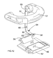
- FIG. 12 is a perspective view of a handle, guard and locking mechanism of the sander of FIG. 1 , with the guard and handle in a lower position;
- FIG. 13 is a view, corresponding to FIG. 12 , with the handle in a raised position;
- FIG. 14 is a view, corresponding to FIG. 12 , with the handle and guard in raised positions;
- FIG. 15 is a front view of the handle, guard and locking mechanism of FIG. 12 ;
- FIG. 16 is a top view of the handle, guard and locking mechanism of FIG. 12 ;
- FIG. 17 is a rear view of the handle, guard and locking mechanism of FIG. 14 .
- a belt sander 2 has a housing 4 of durable plastics material and having a generally wedge shaped base portion 5 defining a generally flat base surface 6 and a rear handle 8 having a trigger 10 .
- Flat base surface 6 may comprise a separate metal plate attached to base portion 5 .
- a power cable (not shown) extends from the handle 8 for supplying electrical power to the sander 2 .
- a forward handle 12 is pivotable about pivot axis 14 relative to the housing 4 and is lockable in selected angular positions relative to the housing by means of a locking lever 16 which is pivoted outwardly of the housing 4 in the direction of arrow A ( FIG. 1 ) to release the handle 12 and is pivoted inwardly to lock the handle 12 .
- Pivot axis 14 extends substantially transversely to a vertical plane containing the major axis of sander 2 and base portion 5 .
- the major axis extends horizontally (left to right) on the page of FIG. 2 and the vertical plane containing the axis extends perpendicularly to the page in FIG. 3 .
- the handle 12 is provided with suitable engaging means, which will be familiar to persons skilled in the art, which locate the handle 12 at selected angular positions about pivot axis 14 .
- the lever 16 can operate in a number of possible ways, for example by means of cooperating cam surfaces. This enables the user to choose the most ergonomic position of the handle 12 for the particular task.
- the housing 4 also defines a duct 18 ( FIG. 9 ) connecting an inlet 20 in the base 5 of the housing with a motor 22 having an output shaft 24 which also carries a fan (not shown).
- the fan displaces air radially outwardly through an outlet 28 into a dust bag (not shown).
- the fan is surrounded by a closely fitting flange to divide the space occupied by the fan into a clean air chamber axially separated from a dirty air chamber. Air drawn into the clean air chamber through air inlets 26 in one or both sides of the housing 4 cools the motor, while air is drawn into the dirty air chamber through inlet 20 via duct 18 , and all of the air drawn into the fan is expelled through outlet 28 .
- dust produced by the sanding operation is drawn through inlet 20 and expelled into the dust bag, in a manner described in greater detail below.
- Housing 4 includes cylindrical motor receiving chamber 41 disposed at a location between the locations of front roller 34 and rear roller 32 taken along a major axis of sander 2 .
- Chamber 41 is disposed at a higher vertical position than both rollers 32 and 34 .
- Motor 22 is received within chamber 41 .
- the output shaft 24 of the motor 22 is rotatable about axis 24 a which is substantially transverse to the major axis and carries a gear 25 for driving a toothed belt 30 ( FIG. 10 ) which passes around a gear 33 mounted to a rear roller 32 arranged in a lower part of the housing 4 above inlet 20 .
- the gear 33 is rotatable about axis 32 a and has larger diameter than the gear 25 , which enables the rotational speed of the rear roller 32 to be chosen.
- the axes 24 a and 32 a are generally parallel to each other, which enables the motor 22 to be located above the base portion 5 and laterally in line therewith, which in turn enables compact construction of the sander.
- a front roller 34 having smaller diameter than the rear roller 32 , is arranged in the lower part of the housing such that a lowermost point 36 of the front roller is in line with the base surface 6 .
- the front roller 34 is of concave cross-section to assist in retaining in position an endless sanding belt 38 ( FIG.
- Front roller 34 , rear roller 32 and base 5 jointly define a path for receiving belt 38 of standard size, that is, having a width of seventy five mm (usually expressed as three inches) transverse to the major axis and having a perimeter of either eighteen or twenty one inches.
- the rear roller 32 is generally tangential to an upper surface 7 of wedge shaped base portion 5 , but is offset relative to the flat base surface 6 , as a result of which the direction of belt 38 changes as it passes around rear edge 6 a of base surface 6 , so that the belt 38 is asymmetrically arranged relative to a line joining the central axes of front and rear rollers 34 , 32 .
- Housing 4 includes an undersurface 43 which extends at a forwardly downwardly inclined angle from a location above rear roller 32 towards front roller 34 .
- the overall inclination angle of undersurface 43 may be ten degrees relative to the horizontal.
- the gripping surface of handle 12 is curved and is located generally within a plane which extends in a direction transverse to the major axis of sander 2 .
- Handle 12 is secured to an upper portion of motor receiving chamber 41 , at a location between the locations of front roller 34 and rear roller 32 taken along a major axis of sander 2 .
- handle 12 is disposed at a higher vertical position than both rollers 32 and 34 .
- the front roller 34 is slidably mounted to the front of the base part 5 of the housing 4 by means of a support 44 , and the support 44 is urged forwardly by a compression spring (not shown) to maintain the tension in the sanding belt 38 .
- a lever 46 on the base part 5 of the housing can be pivoted outwards in the direction of arrow B shown in FIG. 1 to place the spring under compression by means of a cam surface to enable the support 44 to be moved inwardly to remove the sanding belt 38 for replacement or for adjustment.
- the front roller 34 is also provided with an adjustment knob 35 for adjusting the angle of the longitudinal axis of the roller 34 relative to the housing 34 .
- the upper sanding surface 42 is covered by a guard 48 which is pivotable relative to the housing about an axis 50 between a lower position and an upper position. In the lower position the guard 48 covers the upper sanding surface 42 and prevents access to it and a front portion 52 of the guard extends forwardly of forwardmost part 54 of the sanding belt 38 . In the upper position of the guard 48 , access to the upper sanding surface 42 is permitted, for example for sanding the underside of objects such as tables, or for sanding non-level surfaces such as door frames.
- a rear part 56 of the guard 48 has a cam 58 ( FIG. 13 ) having a cam surface 60 on a side thereof which cooperates with a side surface of an end 62 of a linkage member 64 mounted to a pivot 66 .
- a cam 58 FIG. 13
- movement of the guard 48 from its lower to its upper position causes the cam surface 60 to displace end 62 of the linkage member 64 to the left in FIG. 13 , which then urges the linkage member 64 in a clockwise direction about the pivot 66 in the direction of arrow C in FIG. 13 .
- the linkage member 64 is received in a slot 68 in the handle 12 when the guard 48 is in its upper position and when the handle 12 is pivoted upwardly relative to the housing 4 as shown in FIG.
- the guard 48 covers the upper sanding surface 42 , and the handle 12 is locked in any one of its permitted angular positions about axis 14 relative to the housing by means of the locking lever 16 .
- the user actuates the motor by pressing trigger 10 on handle 8 , as a result of which the motor 22 drives rear roller 32 to cause movement of the sanding belt 38 around front 34 and rear 32 rollers and upper 40 and lower 42 sanding surfaces in the direction of arrow D shown in FIG. 9 .
- rotation of the fan creates an air current entering inlet 20 .
- the forwardmost part of the lower sanding surface 40 is defined by the lowermost 36 part of the front roller 34 , only that part of the sander 2 forwardly of the rotation axis of the front roller 34 lies above the forwardmost part of the lower sanding surface 40 .
- the sander 2 can be used to sand much closer to the edge of floors than is the case with conventional sanders.
- the present invention provides the material removal capabilities of a full size belt sander but allows sanding much closer to a vertical wall.
- front roller 34 may have a maximum diameter of approximately 23 mm and preferably a diameter of 16.5 mm.
- This structure allows the sander to sand within 15 mm of the vertical wall. Including base surface 6 , this structure allows the sanding belt to contact the sanded surface for a length of approximately 195 mm along the major axis.
- Contact between the front part 54 of the sanding belt 38 and a vertical surface such as a wall (not shown) is prevented by the front portion 52 of the guard 48 , which extends forwardly of the front part 54 of the belt 38 by approximately 5 mm when the guard 48 is in its lower position. This prevents inadvertent damage to, for example, skirting boards at the edge of a floor to be sanded.
- the locking lever 16 is pivoted outwardly of the housing 4 to enable pivoting of the handle 12 about axis 14 , and the handle 12 is pivoted to its upper position, as a result of which the upper part 70 of linkage member 64 is aligned with slot 68 in the handle 12 to allow the linkage member 64 to pivot about pivot 66 .
- the guard 48 is then pivoted upwardly by means of a suitable actuator member (not shown), for example a lever located adjacent pivot axis 50 to expose the upper sanding surface 42 .
- the guard 48 is then retained in its upper position by suitable means.
- the sander of the present invention also allows for sanding beneath an overhanging edge.
- the upper surface of base 5 has a forwardly downward inclination.
- Undersurface 43 has a corresponding downward inclination.
- This inclination along with the relatively flat upper surface of housing 4 disposed forwardly of motor receiving chamber 41 , and the fact that no portion of the housing extends above this flat upper surface permits the forward end of sander 2 to pass readily beneath an overhanging edge.
- This structure along with the minimized diameter of front roller 34 allows sanding of a horizontal surface to nearly the edge of such a surface extending beneath the overhanging edge.
- the flat upper surface may extend approximately 64 mm in the rearward direction from the forward end of housing 4 , and throughout its extent, the flat upper surface is disposed no greater than approximately 36 mm above the lower sanding surface, with no other portion of the housing disposed or extending above the flat upper surface.
- the diameter of rear roller 32 approximately corresponds to the height of base 5 at the rear edge thereof.
- the rear roller 32 may have a diameter which is in a range of 2–3 times the diameter of front roller 34 .
- the diameter of rear roller 32 is 48 mm, or approximately 3 times the front roller 34 .
- the flat upper surface of housing 4 is formed by the upper surface of guard 48 .
- the lever 46 When the sanding belt 38 becomes worn, the lever 46 is pivoted outwardly of the housing 4 to compress the compression spring (not shown). This allows support 44 to be moved rearwardly, as a result of which the belt 38 becomes slack and can more easily be removed for replacement. When a replacement belt 38 has been placed around the rollers 32 , 34 , the lever 46 is then pivoted inwardly to cause the spring to urge the forward roller 34 forwards to place the replacement belt 38 under tension.
- housing 4 includes a rear flat upper surface extending rearwardly from motor receiving chamber 41 , preferably for a distance of at least 50 mm. Housing 4 then curves downwardly about rear roller 32 , and handle support portion 45 extends rearwardly therefrom. Rear handle 8 extends rearwardly from motor receiving chamber 41 and terminates at support portion 45 . Therefore, a gripping surface of handle 8 extends above rear roller 32 , providing increased control for belt sander 2 . Trigger 10 is disposed at the underside of the gripping surface of handle 8 . The maxiumum height of sander 2 at the location of the rear flat upper surface may be 68 mm.
Landscapes
- Engineering & Computer Science (AREA)
- Mechanical Engineering (AREA)
- Finish Polishing, Edge Sharpening, And Grinding By Specific Grinding Devices (AREA)
- Golf Clubs (AREA)
Applications Claiming Priority (2)
| Application Number | Priority Date | Filing Date | Title |
|---|---|---|---|
| EPEP04253394.3 | 2004-06-07 | ||
| EP04253394A EP1604780B1 (de) | 2004-06-07 | 2004-06-07 | Schmirgelmaschine |
Publications (2)
| Publication Number | Publication Date |
|---|---|
| US20050272357A1 US20050272357A1 (en) | 2005-12-08 |
| US7018280B2 true US7018280B2 (en) | 2006-03-28 |
Family
ID=34930383
Family Applications (1)
| Application Number | Title | Priority Date | Filing Date |
|---|---|---|---|
| US10/931,880 Expired - Fee Related US7018280B2 (en) | 2004-06-07 | 2004-09-01 | Sanding apparatus |
Country Status (8)
| Country | Link |
|---|---|
| US (1) | US7018280B2 (de) |
| EP (1) | EP1604780B1 (de) |
| CN (1) | CN100482413C (de) |
| AT (1) | ATE357308T1 (de) |
| AU (1) | AU2004203656A1 (de) |
| CA (1) | CA2476748A1 (de) |
| DE (1) | DE602004005434T2 (de) |
| NZ (1) | NZ534589A (de) |
Cited By (19)
| Publication number | Priority date | Publication date | Assignee | Title |
|---|---|---|---|---|
| US20050272356A1 (en) * | 2004-06-07 | 2005-12-08 | Andrew Walker | Sanding apparatus |
| US20070197151A1 (en) * | 2005-03-24 | 2007-08-23 | Wall Daniel P | Belt sander |
| USD556001S1 (en) * | 2005-11-30 | 2007-11-27 | Black & Decker Inc. | Belt sander |
| USD570173S1 (en) | 2007-08-23 | 2008-06-03 | Black & Decker Inc. | Belt sander |
| USD570661S1 (en) | 2007-08-23 | 2008-06-10 | Black & Decker Inc. | Belt sander |
| US20080254723A1 (en) * | 2007-04-12 | 2008-10-16 | Lamarche Paul | Expansible sanding block exhibiting oblique extending surfaces |
| USD637879S1 (en) * | 2010-07-01 | 2011-05-17 | Makita Corporation | Portable electric planer |
| US20110177766A1 (en) * | 2007-04-12 | 2011-07-21 | Lamarche Paul | Expansible sanding block exhibiting oblique extending surfaces |
| US20120156974A1 (en) * | 2010-12-16 | 2012-06-21 | Kundel Jr Robert | Surface preparation apparatus |
| USD683604S1 (en) * | 2010-06-11 | 2013-06-04 | Black & Decker Inc. | Planer |
| US9669508B2 (en) | 2014-10-24 | 2017-06-06 | Velasa Sports, Inc. | Grinding wheel with identification tag |
| USD793830S1 (en) * | 2015-07-08 | 2017-08-08 | Velasa Sports, Inc. | Skate blade sharpening system |
| US20170259392A1 (en) * | 2016-03-10 | 2017-09-14 | Easthill Group, Inc. | Metal finishing rotary tool |
| US9902035B2 (en) | 2014-10-24 | 2018-02-27 | Velasa Sports, Inc. | Compact grinding wheel |
| US10065282B2 (en) | 2015-05-28 | 2018-09-04 | Velasa Sports, Inc. | Skate blade sharpening system with alignment adjustment |
| US10300574B2 (en) | 2014-10-24 | 2019-05-28 | Velasa Sports, Inc. | Skate blade sharpening system |
| US11969851B2 (en) | 2020-07-31 | 2024-04-30 | Velasa Sports, Inc. | Skate blade sharpening system |
| US12485339B2 (en) | 2022-10-14 | 2025-12-02 | Velasa Sports, Inc. | Skate blade clamping systems |
| US12589518B2 (en) | 2022-04-25 | 2026-03-31 | Milwaukee Electric Tool Corporation | Hand-held planning tool |
Families Citing this family (10)
| Publication number | Priority date | Publication date | Assignee | Title |
|---|---|---|---|---|
| US7410412B2 (en) | 2005-01-21 | 2008-08-12 | Black & Decker Inc. | Belt sander |
| US7235005B2 (en) | 2005-03-24 | 2007-06-26 | Black & Decker Inc. | Belt sander |
| US8622786B2 (en) * | 2008-12-10 | 2014-01-07 | Sears Brands, L.L.C. | Interchangeable sanding system |
| DE202010004392U1 (de) * | 2010-03-31 | 2011-08-11 | Illinois Tool Works Inc. | Mauerschlitzfräse |
| CN103962904A (zh) * | 2013-01-28 | 2014-08-06 | 昆山尚达智机械有限公司 | 一种新型全自动打磨机 |
| CN105234786A (zh) * | 2015-09-30 | 2016-01-13 | 河南飞龙(芜湖)汽车零部件有限公司 | 一种排气歧管狭窄空间用打磨装置 |
| SE541067C2 (en) | 2016-06-03 | 2019-03-26 | Husqvarna Ab | Floor grinding machine and method of setting a handle for a floor grinding machine |
| CN108000308A (zh) * | 2017-11-30 | 2018-05-08 | 无锡市中吉橡塑机械有限公司 | 一种用于五金架打磨的打磨装置 |
| CN109531369A (zh) * | 2019-01-07 | 2019-03-29 | 浙江机电职业技术学院 | 一种手持式自动打磨装置 |
| WO2022221174A1 (en) * | 2021-04-12 | 2022-10-20 | Milwaukee Electric Tool Corporation | Belt sander |
Citations (23)
| Publication number | Priority date | Publication date | Assignee | Title |
|---|---|---|---|---|
| US1523151A (en) * | 1920-10-14 | 1925-01-13 | Robert W Wilsbach | Abrading and polishing tool |
| US2178865A (en) | 1938-02-02 | 1939-11-07 | Harold A Swan | Abrading and blackboard cleaning machine |
| US2280867A (en) | 1939-10-30 | 1942-04-28 | Harold A Swan | Abrading and blackboard cleaning machine |
| US3334447A (en) | 1965-09-28 | 1967-08-08 | Treffle J Leveque | Sanding machine |
| US3359689A (en) | 1965-04-22 | 1967-12-26 | Black & Decker Mfg Co | Tracking means for belt sander |
| DE1690005A1 (de) | 1967-07-27 | 1971-04-15 | Siemens Ag | Schwenkbares Rahmengestell zur Aufnahme von Gestelleinschueben der elektrischen Nachrichten- und Messtechnik |
| US3983664A (en) | 1975-11-21 | 1976-10-05 | Ronald Martin | Belt-type sander attachment for portable power drills |
| DE7718737U1 (de) | 1977-06-14 | 1977-10-06 | Eisenblaetter, Rolf, 8192 Geretsried | Von hand fuehrbare einrichtung zum schleifen und/oder buersten von werkstueckoberflaechen |
| DE3031877A1 (de) | 1980-08-23 | 1982-04-01 | Eugen Lutz GmbH u. Co Maschinenfabrik, 7130 Mühlacker | Vorrichtung zum kuehlen von schleifwerkzeugen |
| DE3117785A1 (de) | 1981-05-06 | 1982-11-18 | Festo-Maschinenfabrik Gottlieb Stoll, 7300 Esslingen | "bandschleifgeraet" |
| DE3919651A1 (de) | 1989-06-16 | 1990-12-20 | Bosch Gmbh Robert | Handbandschleifmaschine |
| US5224301A (en) * | 1992-03-20 | 1993-07-06 | James Tasikas | Dual mode floor sander |
| EP0573826A1 (de) | 1992-06-06 | 1993-12-15 | Robert Bosch Gmbh | Motorgetriebener Handbandschleifer |
| EP0611632A1 (de) | 1993-01-30 | 1994-08-24 | Robert Bosch Gmbh | Beidhändig geführtes Elektrohandwerkzeug mit Griffbügel |
| GB2321610A (en) | 1997-02-04 | 1998-08-05 | Bosch Gmbh Robert | Hand belt sander. |
| DE19720691A1 (de) | 1997-05-16 | 1998-11-19 | Bosch Gmbh Robert | Bandschleifmaschine |
| EP1013376A2 (de) | 1998-12-21 | 2000-06-28 | Ykk Corporation | Schleifleinenhalterung |
| US6126529A (en) * | 1999-06-10 | 2000-10-03 | Heyer; Thomas | Belt sander stabilizer |
| JP2000280157A (ja) | 1999-03-30 | 2000-10-10 | Ryobi Ltd | ベルトサンダ |
| US6159085A (en) * | 1997-10-16 | 2000-12-12 | Makita Corporation | Structure for use in a power driven tool for collecting dust generated by the operation of the tool |
| US6475075B1 (en) * | 2000-02-03 | 2002-11-05 | Robert Bosch Gmbh | Hand operated belt sander |
| DE10200489A1 (de) | 2002-01-07 | 2003-07-24 | Preuss Rolf | Kombinationsbandschleifgerät |
| USD497298S1 (en) * | 2003-12-16 | 2004-10-19 | One World Technologies, Limited | Belt sander |
-
2004
- 2004-06-07 EP EP04253394A patent/EP1604780B1/de not_active Expired - Lifetime
- 2004-06-07 AT AT04253394T patent/ATE357308T1/de not_active IP Right Cessation
- 2004-06-07 DE DE602004005434T patent/DE602004005434T2/de not_active Expired - Lifetime
- 2004-08-05 CA CA002476748A patent/CA2476748A1/en not_active Abandoned
- 2004-08-06 AU AU2004203656A patent/AU2004203656A1/en not_active Abandoned
- 2004-08-09 NZ NZ534589A patent/NZ534589A/xx unknown
- 2004-09-01 US US10/931,880 patent/US7018280B2/en not_active Expired - Fee Related
-
2005
- 2005-06-07 CN CNB2005100759874A patent/CN100482413C/zh not_active Expired - Fee Related
Patent Citations (27)
| Publication number | Priority date | Publication date | Assignee | Title |
|---|---|---|---|---|
| US1523151A (en) * | 1920-10-14 | 1925-01-13 | Robert W Wilsbach | Abrading and polishing tool |
| US2178865A (en) | 1938-02-02 | 1939-11-07 | Harold A Swan | Abrading and blackboard cleaning machine |
| US2280867A (en) | 1939-10-30 | 1942-04-28 | Harold A Swan | Abrading and blackboard cleaning machine |
| US3359689A (en) | 1965-04-22 | 1967-12-26 | Black & Decker Mfg Co | Tracking means for belt sander |
| US3334447A (en) | 1965-09-28 | 1967-08-08 | Treffle J Leveque | Sanding machine |
| DE1690005A1 (de) | 1967-07-27 | 1971-04-15 | Siemens Ag | Schwenkbares Rahmengestell zur Aufnahme von Gestelleinschueben der elektrischen Nachrichten- und Messtechnik |
| US3983664A (en) | 1975-11-21 | 1976-10-05 | Ronald Martin | Belt-type sander attachment for portable power drills |
| US4118897A (en) | 1975-11-21 | 1978-10-10 | Ronald Martin | Belt-type sander accessory |
| DE7718737U1 (de) | 1977-06-14 | 1977-10-06 | Eisenblaetter, Rolf, 8192 Geretsried | Von hand fuehrbare einrichtung zum schleifen und/oder buersten von werkstueckoberflaechen |
| DE3031877A1 (de) | 1980-08-23 | 1982-04-01 | Eugen Lutz GmbH u. Co Maschinenfabrik, 7130 Mühlacker | Vorrichtung zum kuehlen von schleifwerkzeugen |
| DE3117785A1 (de) | 1981-05-06 | 1982-11-18 | Festo-Maschinenfabrik Gottlieb Stoll, 7300 Esslingen | "bandschleifgeraet" |
| DE3919651A1 (de) | 1989-06-16 | 1990-12-20 | Bosch Gmbh Robert | Handbandschleifmaschine |
| US5224301A (en) * | 1992-03-20 | 1993-07-06 | James Tasikas | Dual mode floor sander |
| EP0573826A1 (de) | 1992-06-06 | 1993-12-15 | Robert Bosch Gmbh | Motorgetriebener Handbandschleifer |
| EP0611632A1 (de) | 1993-01-30 | 1994-08-24 | Robert Bosch Gmbh | Beidhändig geführtes Elektrohandwerkzeug mit Griffbügel |
| GB2321610A (en) | 1997-02-04 | 1998-08-05 | Bosch Gmbh Robert | Hand belt sander. |
| US6419569B1 (en) | 1997-02-04 | 2002-07-16 | Robert Bosch Gmbh | Hand-held belt sander |
| US6174226B1 (en) | 1997-02-04 | 2001-01-16 | Robert Bosch Gmbh | Hand-held belt sander |
| DE19720691A1 (de) | 1997-05-16 | 1998-11-19 | Bosch Gmbh Robert | Bandschleifmaschine |
| US6159085A (en) * | 1997-10-16 | 2000-12-12 | Makita Corporation | Structure for use in a power driven tool for collecting dust generated by the operation of the tool |
| US6379236B1 (en) | 1998-12-21 | 2002-04-30 | Ykk Corporation | Fixture for abrasive cloth paper |
| EP1013376A2 (de) | 1998-12-21 | 2000-06-28 | Ykk Corporation | Schleifleinenhalterung |
| JP2000280157A (ja) | 1999-03-30 | 2000-10-10 | Ryobi Ltd | ベルトサンダ |
| US6126529A (en) * | 1999-06-10 | 2000-10-03 | Heyer; Thomas | Belt sander stabilizer |
| US6475075B1 (en) * | 2000-02-03 | 2002-11-05 | Robert Bosch Gmbh | Hand operated belt sander |
| DE10200489A1 (de) | 2002-01-07 | 2003-07-24 | Preuss Rolf | Kombinationsbandschleifgerät |
| USD497298S1 (en) * | 2003-12-16 | 2004-10-19 | One World Technologies, Limited | Belt sander |
Cited By (29)
| Publication number | Priority date | Publication date | Assignee | Title |
|---|---|---|---|---|
| US7226346B2 (en) * | 2004-06-07 | 2007-06-05 | Black & Decker Inc. | Sanding apparatus |
| US20050272356A1 (en) * | 2004-06-07 | 2005-12-08 | Andrew Walker | Sanding apparatus |
| US7871311B2 (en) * | 2005-03-24 | 2011-01-18 | Black & Decker Inc. | Belt sander |
| US20070197151A1 (en) * | 2005-03-24 | 2007-08-23 | Wall Daniel P | Belt sander |
| USD556001S1 (en) * | 2005-11-30 | 2007-11-27 | Black & Decker Inc. | Belt sander |
| US20080254723A1 (en) * | 2007-04-12 | 2008-10-16 | Lamarche Paul | Expansible sanding block exhibiting oblique extending surfaces |
| US20110177766A1 (en) * | 2007-04-12 | 2011-07-21 | Lamarche Paul | Expansible sanding block exhibiting oblique extending surfaces |
| US8011998B2 (en) * | 2007-04-12 | 2011-09-06 | Lamarche Paul | Expansible sanding block exhibiting oblique extending surfaces |
| US8231440B2 (en) | 2007-04-12 | 2012-07-31 | Lamarche Paul | Expansible sanding block exhibiting oblique extending surfaces |
| USD570661S1 (en) | 2007-08-23 | 2008-06-10 | Black & Decker Inc. | Belt sander |
| USD570173S1 (en) | 2007-08-23 | 2008-06-03 | Black & Decker Inc. | Belt sander |
| USD683604S1 (en) * | 2010-06-11 | 2013-06-04 | Black & Decker Inc. | Planer |
| USD637879S1 (en) * | 2010-07-01 | 2011-05-17 | Makita Corporation | Portable electric planer |
| US8480457B2 (en) * | 2010-12-16 | 2013-07-09 | Robert Kundel, JR. | Surface preparation apparatus |
| US20120156974A1 (en) * | 2010-12-16 | 2012-06-21 | Kundel Jr Robert | Surface preparation apparatus |
| US12186854B1 (en) | 2014-10-24 | 2025-01-07 | Velasa Sports, Inc. | Skate blade sharpening system |
| US12508684B2 (en) | 2014-10-24 | 2025-12-30 | Velasa Sports, Inc. | Skate blade sharpening system |
| US9902035B2 (en) | 2014-10-24 | 2018-02-27 | Velasa Sports, Inc. | Compact grinding wheel |
| US10300574B2 (en) | 2014-10-24 | 2019-05-28 | Velasa Sports, Inc. | Skate blade sharpening system |
| US11919119B2 (en) | 2014-10-24 | 2024-03-05 | Velasa Sports, Inc. | Skate blade sharpening system |
| US9669508B2 (en) | 2014-10-24 | 2017-06-06 | Velasa Sports, Inc. | Grinding wheel with identification tag |
| US12214467B2 (en) | 2014-10-24 | 2025-02-04 | Velasa Sports, Inc. | Skate blade sharpening system |
| US10065282B2 (en) | 2015-05-28 | 2018-09-04 | Velasa Sports, Inc. | Skate blade sharpening system with alignment adjustment |
| USD793830S1 (en) * | 2015-07-08 | 2017-08-08 | Velasa Sports, Inc. | Skate blade sharpening system |
| US20170259392A1 (en) * | 2016-03-10 | 2017-09-14 | Easthill Group, Inc. | Metal finishing rotary tool |
| US11969851B2 (en) | 2020-07-31 | 2024-04-30 | Velasa Sports, Inc. | Skate blade sharpening system |
| US12337436B2 (en) | 2020-07-31 | 2025-06-24 | Velasa Sports, Inc. | Skate blade sharpening system |
| US12589518B2 (en) | 2022-04-25 | 2026-03-31 | Milwaukee Electric Tool Corporation | Hand-held planning tool |
| US12485339B2 (en) | 2022-10-14 | 2025-12-02 | Velasa Sports, Inc. | Skate blade clamping systems |
Also Published As
| Publication number | Publication date |
|---|---|
| AU2004203656A1 (en) | 2005-12-22 |
| CN100482413C (zh) | 2009-04-29 |
| EP1604780B1 (de) | 2007-03-21 |
| CN1706593A (zh) | 2005-12-14 |
| ATE357308T1 (de) | 2007-04-15 |
| NZ534589A (en) | 2006-03-31 |
| DE602004005434T2 (de) | 2007-11-29 |
| US20050272357A1 (en) | 2005-12-08 |
| DE602004005434D1 (de) | 2007-05-03 |
| EP1604780A1 (de) | 2005-12-14 |
| CA2476748A1 (en) | 2005-12-07 |
Similar Documents
| Publication | Publication Date | Title |
|---|---|---|
| US7018280B2 (en) | Sanding apparatus | |
| US7226346B2 (en) | Sanding apparatus | |
| US5199220A (en) | Combination belt and disc sander | |
| EP2000272B1 (de) | Fliesenschneidemaschine | |
| US10144144B2 (en) | Power tool cutting apparatus | |
| EP2000273B1 (de) | Fliesensäge mit Laserführung | |
| US8046922B2 (en) | Cutting device | |
| US5347902A (en) | Motorized miter box | |
| EP2946896B1 (de) | Fliesenschneidemaschine | |
| US8176823B2 (en) | Miter saw with bevel lock arrangement | |
| US20100269661A1 (en) | Miter saw with work surface extensions | |
| US20110247460A1 (en) | Reciprocating skate blade sharpener | |
| US7624775B2 (en) | Power planer | |
| US6951231B2 (en) | Planer apparatus | |
| CA2375002C (en) | Grinding machine having adjustable mechanism | |
| US6532643B2 (en) | Table tool having a movable shield | |
| US5964654A (en) | Multiple abrasive belt machine | |
| US20230390837A1 (en) | Coping system | |
| JPH11114945A (ja) | 揺動式カッタ−装置 | |
| JPH11114950A (ja) | カッタ−装置 | |
| CA2169452A1 (en) | Finishing machine | |
| JP2021024207A (ja) | 補助ベースおよび卓上切断機 |
Legal Events
| Date | Code | Title | Description |
|---|---|---|---|
| AS | Assignment |
Owner name: BLACK & DECKER, INC., DELAWARE Free format text: ASSIGNMENT OF ASSIGNORS INTEREST;ASSIGNOR:WALKER, ANDREW;REEL/FRAME:015516/0842 Effective date: 20041012 |
|
| FPAY | Fee payment |
Year of fee payment: 4 |
|
| FPAY | Fee payment |
Year of fee payment: 8 |
|
| FEPP | Fee payment procedure |
Free format text: MAINTENANCE FEE REMINDER MAILED (ORIGINAL EVENT CODE: REM.) |
|
| LAPS | Lapse for failure to pay maintenance fees |
Free format text: PATENT EXPIRED FOR FAILURE TO PAY MAINTENANCE FEES (ORIGINAL EVENT CODE: EXP.) |
|
| STCH | Information on status: patent discontinuation |
Free format text: PATENT EXPIRED DUE TO NONPAYMENT OF MAINTENANCE FEES UNDER 37 CFR 1.362 |
|
| FP | Lapsed due to failure to pay maintenance fee |
Effective date: 20180328 |