US7307710B2 - Surveying methods and apparatus - Google Patents
Surveying methods and apparatus Download PDFInfo
- Publication number
- US7307710B2 US7307710B2 US11/159,431 US15943105A US7307710B2 US 7307710 B2 US7307710 B2 US 7307710B2 US 15943105 A US15943105 A US 15943105A US 7307710 B2 US7307710 B2 US 7307710B2
- Authority
- US
- United States
- Prior art keywords
- target
- total station
- identification
- wireless communication
- modulation scheme
- Prior art date
- Legal status (The legal status is an assumption and is not a legal conclusion. Google has not performed a legal analysis and makes no representation as to the accuracy of the status listed.)
- Expired - Lifetime
Links
- 238000000034 method Methods 0.000 title claims abstract description 26
- 238000004891 communication Methods 0.000 claims abstract description 83
- 238000005259 measurement Methods 0.000 claims description 65
- 238000010586 diagram Methods 0.000 description 9
- 230000008901 benefit Effects 0.000 description 7
- 238000010276 construction Methods 0.000 description 6
- 230000001747 exhibiting effect Effects 0.000 description 6
- 230000000694 effects Effects 0.000 description 3
- 238000012546 transfer Methods 0.000 description 3
- 230000003213 activating effect Effects 0.000 description 2
- 230000001413 cellular effect Effects 0.000 description 2
- 230000003287 optical effect Effects 0.000 description 2
- IRLPACMLTUPBCL-KQYNXXCUSA-N 5'-adenylyl sulfate Chemical compound C1=NC=2C(N)=NC=NC=2N1[C@@H]1O[C@H](COP(O)(=O)OS(O)(=O)=O)[C@@H](O)[C@H]1O IRLPACMLTUPBCL-KQYNXXCUSA-N 0.000 description 1
- 238000012935 Averaging Methods 0.000 description 1
- 238000013500 data storage Methods 0.000 description 1
- 230000001419 dependent effect Effects 0.000 description 1
- 238000013461 design Methods 0.000 description 1
- 238000001514 detection method Methods 0.000 description 1
- 230000014509 gene expression Effects 0.000 description 1
- 230000003993 interaction Effects 0.000 description 1
- 238000000926 separation method Methods 0.000 description 1
- 230000001360 synchronised effect Effects 0.000 description 1
Images


Classifications
-
- G—PHYSICS
- G01—MEASURING; TESTING
- G01S—RADIO DIRECTION-FINDING; RADIO NAVIGATION; DETERMINING DISTANCE OR VELOCITY BY USE OF RADIO WAVES; LOCATING OR PRESENCE-DETECTING BY USE OF THE REFLECTION OR RERADIATION OF RADIO WAVES; ANALOGOUS ARRANGEMENTS USING OTHER WAVES
- G01S5/00—Position-fixing by co-ordinating two or more direction or position line determinations; Position-fixing by co-ordinating two or more distance determinations
- G01S5/0009—Transmission of position information to remote stations
- G01S5/0018—Transmission from mobile station to base station
-
- G—PHYSICS
- G01—MEASURING; TESTING
- G01C—MEASURING DISTANCES, LEVELS OR BEARINGS; SURVEYING; NAVIGATION; GYROSCOPIC INSTRUMENTS; PHOTOGRAMMETRY OR VIDEOGRAMMETRY
- G01C15/00—Surveying instruments or accessories not provided for in groups G01C1/00 - G01C13/00
-
- G—PHYSICS
- G01—MEASURING; TESTING
- G01S—RADIO DIRECTION-FINDING; RADIO NAVIGATION; DETERMINING DISTANCE OR VELOCITY BY USE OF RADIO WAVES; LOCATING OR PRESENCE-DETECTING BY USE OF THE REFLECTION OR RERADIATION OF RADIO WAVES; ANALOGOUS ARRANGEMENTS USING OTHER WAVES
- G01S13/00—Systems using the reflection or reradiation of radio waves, e.g. radar systems; Analogous systems using reflection or reradiation of waves whose nature or wavelength is irrelevant or unspecified
- G01S13/87—Combinations of radar systems, e.g. primary radar and secondary radar
- G01S13/878—Combination of several spaced transmitters or receivers of known location for determining the position of a transponder or a reflector
-
- G—PHYSICS
- G01—MEASURING; TESTING
- G01S—RADIO DIRECTION-FINDING; RADIO NAVIGATION; DETERMINING DISTANCE OR VELOCITY BY USE OF RADIO WAVES; LOCATING OR PRESENCE-DETECTING BY USE OF THE REFLECTION OR RERADIATION OF RADIO WAVES; ANALOGOUS ARRANGEMENTS USING OTHER WAVES
- G01S17/00—Systems using the reflection or reradiation of electromagnetic waves other than radio waves, e.g. lidar systems
- G01S17/74—Systems using reradiation of electromagnetic waves other than radio waves, e.g. IFF, i.e. identification of friend or foe
Definitions
- the present invention generally relates to surveying and more specifically to a surveying system including several surveying units for surveying and equipment such as targets, radio receivers and methods and means for co-operation between such units.
- the art of surveying involves the determination of unknown positions or setting out of known coordinates using angle and distance measurements taken from one or more known positions.
- a surveying device frequently used is a total station.
- the device is generally operated by two users, one user pointing the total station at a target held by a second user.
- Robotic total stations have been developed which assist the user in locating the target and aligning to it.
- the robotic total stations include servomotors that allow the apparatus to be rotated to automatically align the station with the target.
- the automatic alignment can be done either against the reflector used for distance measurement, in which case a separate light (IR or visible) beam is sent from the robotic total station and reflected back from the reflector, or the target may be equipped with a light source.
- the total station is equipped with an optical receiver to receive the alignment signal reflected from the reflector or transmitted from the light source, to be processed and used to automatically align the total station against the target.
- an optical receiver to receive the alignment signal reflected from the reflector or transmitted from the light source, to be processed and used to automatically align the total station against the target.
- These robotic total stations can automatically find a target, lock to it and follow the target if it is moved.
- the user may be only one person and he is then normally working at the target in order to choose the point to be measured or mark the point to be set out.
- the user can make the station search for the target and lock to it.
- the total station has to be moved to a new location in order to measure further points on the site.
- To move the total station requires not only the physical movement of the apparatus, but also, every time the station is moved, the exact location and orientation of the station has to be determined anew.
- the measurements have to be exact in order to correlate the new measurements to the earlier by establishing the location and the orientation of the station in relation to known reference points. Understandably this takes time, typically 30 minutes or more, and the users dependent on the total station for staking out will then have to wait, not only for the station to be moved, but also for the location and direction to be established in the new position.
- the prior art does not address the problem of selecting a specific target among several possible targets, when the targets appear to be closely located as viewed from the total station.
- a further problem is encountered when several targets and several total stations are located on the same general site; the problem of unique identification of all elements in the survey for proper linking of target with total station is further compounded when there are different users in the same general site.
- Embodiments in accordance with the invention have one or more advantages, such as
- Embodiments in accordance with the present invention provide systems and methods for determining positions, comprising one or more total station(s) and one or more target(s), wherein each unit comprises a two way wireless data communication device to be able to communicate with all possible units in the system in a radio net, each unit having a unique address to be used to enable exchange of commands or data between certain units.
- Embodiments of a surveying system in accordance with the invention comprise at least one total station unit, and at least one target unit, said units having wireless communication system means, each unit provided with a unique address for wireless communication, the wireless communication usable for activating a selected total station to identify and measure the location of a chosen target, each target having identification means used by the total station for identification of the chosen target, each total station having identifier means used for identification the chosen target to be measured.
- the location may according to embodiments of the invention be measured in relation to a relative reference system.
- a system according to embodiments of the invention may further have identification means of each target in the system comprising a modulated light source, each of the targets exhibiting different modulation schemes for the respective light sources, the identification being the selected modulation scheme.
- the system identification means of each target in the system may comprise a light source of which the modulation scheme may be set from measurement to measurement such as to give the light sources of targets close to each other different modulation schemes, the identification being the selected modulation scheme.
- the identification means of each target in the system may comprise a satellite-positioning system receiver, the identification being the approximate location given by the positioning system.
- each target is provided with wireless communication means, and a unique wireless communication address for wireless communication, the wireless communication to be used to activate a selected total station to identify and measure the location of the target in relation to a relative reference system, the target having identification means to be used by the total station for identification of the chosen target.
- the identification means of the target may comprise a modulated light source, the target exhibiting different modulation schemes for the light sources, the identification being the selected modulation schemes.
- the identification means of the target may comprise a light source of which the modulation scheme may be selected from measurement to measurement, the identification being the selected modulation scheme.
- the identification means of the target may comprise a satellite-positioning system receiver, the identification being the approximate location given by the positioning system.
- the measurement data may be sent by wireless communication to a memory means.
- the identification means may comprise a modulated light source, the modulation scheme for the light sources being unique to the target, the identification being the selected modulation scheme.
- the identification means may comprise a light source of which the modulation scheme may be set from measurement to measurement, the identification being the selected modulation scheme.
- the identification means may comprise a satellite-positioning system receiver, the identification being the approximate location given by the positioning system.
- Embodiments of a target in accordance with the invention comprise a reflector to be used as a target for the distance meter in the total station, a means for enabling the robotic total station to lock on the target, and an identification means, which positively identifies the target to the total station to lock unto the identified target.
- the identification means at the target may e.g. be either a modulated light source using a selectable modulation scheme, or a GPS receiver to determine the coarse position of the target, the identifying parameter in the first case being the selected modulation scheme and in the second case the coarse position. This identification means is used to enable any total station to determine that a specific target has been identified before locking on it.
- the means at the target for enabling the station to lock onto the target may be the reflector itself or an additional means, e.g., a light source.
- This second light source may be identical to the identification means, also when that is a modulated light source.
- Embodiments in accordance with the present invention also provide a unique address for all units in the system to be used in a radio communication net, enabling each unit to select one specific unit for a specific communication.
- the identification of a certain target is achieved using a modulated light source, as the identification means on the target, where the modulation scheme (e.g. the modulation frequency) can be changed.
- the modulation scheme e.g. the modulation frequency
- Any of a number of predetermined characteristics can be activated by the operator or by a command from one of the other units in the system.
- the total station can use this specific modulation scheme in different ways.
- the total station may in one embodiment identify the specific modulation “on the run” when scanning for the target, and thus neglect all other targets and when the selected target has been identified the station is allowed to lock to the specific target.
- the total station may in a second embodiment first lock to a target, during the search procedure for a specific target, and then check the modulation scheme to establish if the actual target locked to was the intended one.
- the specific target may, as is already known within the art, comprise a GPS-receiver at the target for determining its position.
- the identification means of the selected target will in this embodiment consist of the position given by the GPS-receiver.
- This information may be translated to a specific total station via the radio communication (wireless link) provided, using the unique address of the specific total station. The total station may then, using the translated positional data, align with the actual target and lock to it.
- the user In a survey where several robotic total stations are used, the user is preferably working at the target.
- the means for radio communication will then enable the user to select one or more of the possible total stations to lock on the specific target and to measure the location thereof.
- Providing the targets with a specific identification means e.g. a specific modulation scheme also allows more than one user to use the same target on a location and discriminate it from other targets.
- This common specific target may be a target used as a reference target on the location.
- Using more than one total station also provides for savings in time in that e.g. in the staking for a road one station may be moved and realigned and the position thereof be ascertained while the surveyor/s keep on measuring and staking out points using another total station.
- the communication will also facilitate for the different units to have access to a common database containing construction data to be used for the survey.
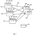
- FIG. 1 is a schematic illustration of a preferred embodiment of a system according to the invention.
- FIG. 2 is a schematic illustration of a method of using the system in connection with road construction or the like.
- FIG. 3 is a schematic illustration of a method of using the system at a site where moving construction machines are used.
- FIG. 4 shows a flowchart of the operation of a system according to the invention.
- FIG. 5 is a schematic block diagram of a surveying target in accordance with the invention.
- FIG. 6 is a schematic block diagram of a robotic total station in accordance with the invention.
- FIG. 7 is a schematic diagram of a surveying system in accordance with the invention.
- FIG. 8 is a flow diagram illustrating surveying methods in accordance with the invention.
- FIG. 1 In a preferred embodiment of the invention, several total stations and targets interact as is shown in the schematic drawing in FIG. 1 .
- Three total stations 110 , 120 , 130 are shown, each having arrangements 111 , 121 , 131 for sending out measuring beams for distance and alignment measurements, and beams, and sensor arrangements 112 , 122 , 132 for receiving the reflected or the transmitted beams from a target.
- the sensor for receiving the alignment beam may be adapted to receive the beam from an identification unit at the target, or a separate sensor may be used for detection of this identification.
- Optical alignment means may be arranged in order to align the total station(s) with any known point (not shown). Also provided are units for two-way wireless data communication, 113 , 123 , and 133 , respectively.
- the two-way wireless data communication may be of the cellular type, e.g. AMPS, PCS (Personal Communication Service) CDPD (Cellular Digital Packet Data), and GSM using e.g. GPRS (General Packet Radio Service).
- AMPS Personal Communication Service
- CDPD Cellular Digital Packet Data
- GSM Global System for Mobile communications
- GPRS General Packet Radio Service
- Bluetooth® or Wi-Fi Wireless Fidelity
- targets 150 , and 160 each target comprising a reflector (not shown) having units 152 and 162 , respectively, for two way wireless data communication and units 154 and 164 for identification of the target.
- the identification units are light sources which may be modulated using different selectable modulation schemes.
- the target may also comprises a control unit (not shown) including a keyboard, a display and a controller to manage the tasks entered via the keyboard and to control the different units.
- the double-headed arrows 140 indicate both the respective data communication and measuring possibilities within the system.
- the system may be further provided with a memory means 170 , for downloading of measurement data from the total stations and the system may also be provided with suitable maps etc. for the surveying work to be done, which may be stored in the memory means.
- the memory means is normally provided in the total station and the control units at the targets but may be provided in a separate computer of e.g. the type PC.
- the user When using the system, the user is preferably stationed at one of the targets 150 , or 160 .
- the user sends a command using the unique address to the appropriate total station, to align with the target having the appropriate modulation scheme and measures the distance and angles from the total station to that target, as is known within the art.
- These measurement data are then stored either locally in the total station, or sent via radio to and stored in the control unit at the target or in the central memory means, which are arranged to be addressable by all units (total station and targets) in the system.
- a second user at target 160 can simultaneously use any non-occupied total station to align to this target and perform corresponding measurements. It has to be understood that a unit occupied with one measuring task will give a notice to any user trying to contact it indicating that it is not available for new task until the first is finished. It is also possible to give users different priorities when asking for service.
- the total stations may be set up in advance in locations on the site, which locations are within measuring distance (line of sight undisturbed) from all possible measurement points on the site, or that at least one total station will be within measuring distance from any chosen point.
- the user may then choose the appropriate total station(s) to perform the measurement(s).
- To be taken into account in this instance is the relative distance to the total station chosen and also the relative locations of the chosen stations(s) i.e. two targets may be too close to each other seen from one total station, but not from another total station. Having more than one total station perform the measurement will ascertain a higher precision overall for the data.
- the site may be a building site where buildings are erected and which will obstruct the view in some directions.
- the site may also be of an undulating type, the ground itself obstructing the view.
- the identification units 154 and 164 at the target comprises GPS receivers. The identification is then performed by determination of the coarse position (in the range up to a few meters) of the target. Instead of transferring the modulation command to the total station as in the preferred embodiment the coarse position data is instead transferred, and by calculating the approximate direction to the target, the total station can find it and lock to it, provided there is no other target close to the same direction.
- FIG. 2 a road construction site is shown, it may as well be a railroad or a run-way.
- three targets 201 , 202 , and 203 for setting out the edges of the roadway.
- the measurements are initiated in the same manner as in the previous embodiment.
- the measurement relative to target 201 , 202 , and 203 are performed in a first round.
- the bi-directional wireless communication paths 241 , as well as the bi-directional measurement beams 240 are both shown.
- the method of locking both total stations 210 and 220 on the same target (in this case 202 ), can serve either as a check that there is no mismatch between the two total stations e.g. the locations and orientations are correct, or data from both stations can be used to get a higher accuracy of the measurement by averaging the measured position of 202 .
- the total stations 210 and 220 There may of course be several more targets, which are within line of sight from the total stations 210 and 220 .
- this station is relocated to a new place as indicated in the drawing by the total station 210 ′ and the dashed arrow 270 .
- the target 201 is transferred to a new location indicated by 201 ′.
- the manner in which the measurement data are stored and collected is the same as the embodiment shown in FIG. 1 .
- a further advantage of the systems according to the invention is that if there are more than one team at a construction site e.g. they may use the other teams units as each unit has a unique address.
- FIG. 3 a site similar to that in FIG. 2 but having a working machine, e.g. a grader 304 is shown.
- the working machine has a target/reflector 303 for measuring the location of the working machine.
- the system shown further comprises two targets 301 and 302 also provided with means for wireless communication and for performing measurements.
- the bi-directional wireless communication paths 341 are indicated, as also the bi-directional measurement beams 340 .
- One or more of the total stations 310 , 320 can be used to lock to the target on the machine 303 to guide the machine and control the working part of the machine via the radio link. More sensors can be provided on the machine to determine the position of the working blade in a site coordinate system to facilitate an exact control of the work done by the machine. As the machine proceeds along the road the tracking has to be taken over by the next total station ( 320 ). When this is achieved the first station can be moved to a new location along the road (indicated as 310 ′), without any interruption for the machine to wait for the transfer. Again using a second ( 302 ) common target for two stations, a check of the consistency of the new location and orientation can be done.
- a preferred method of using the system in FIG. 1 according to the invention may be as follows:
- a transponder adapted to react on a transmitted electromagnetic beam, from the total station as the identification means.
- the transponder will then react and transmit the signal back and possibly add a modulation to the signal.
- FIG. 5 is a schematic block diagram showing an active surveying target 500 in accordance with embodiments of the invention.
- the target includes a reflector on a pole 505 as is conventional for passive surveying targets.
- the target further includes a controller 510 having a data store 515 and input/output devices 520 such as a keypad for receiving commands from a human operator and a display panel for displaying information to be viewed by a human operator.
- a wireless communication unit 525 having an address 530 communicates with controller 510 for sending and receiving data by wireless communication.
- Address 530 is preferably a unique address allowing communications from target 500 to be recognized as coming from it and allowing communications to be addressed to it.
- Identification unit 535 in communication with controller 510 enables a total station to identify target 500 .
- Identification unit 535 can be implemented as (1) a light source such as a laser source which emits light modulated to indicate the identity of the target, (2) a light source such as a laser source which emits a light of a frequency which indicates the identity of the target, and/or (3) a global positioning system receiver to determine and supply an approximate location of the target which indicates the identity of the target.
- the approximate location can be transmitted via modulated light such as a laser and/or via wireless communication.
- the information which indicates identity of the target can optionally be modified by command from the controller so that targets which are located in close proximity to one another are assured of being distinguished from one another by a total station attempting to seek and identify a specific target.
- FIG. 6 is a schematic block diagram of a robotic total station 600 in accordance with the invention.
- Conventional elements of a robotic total station 600 indicated collectively at 605 include a telescope, drive motors for aiming the telescope, angle sensors for detecting azimuth and elevation of the telescope and a distance-measuring unit for measuring distance to a target.
- robotic total station 600 further includes a controller 610 having a data store 615 and input/output devices 620 such as a keypad for receiving commands from a human operator and a display panel for displaying information to be viewed by a human operator.
- a wireless communication unit 625 having an address 630 communicates with controller 610 for sending and receiving data by wireless communication.
- Address 630 is preferably a unique address allowing communications from robotic total station 600 be recognized as coming from it and allowing communications to be addressed to it.
- An identifying unit 635 in communication with controller 510 enables total station 600 to identify a target such as target 500 from a signal received from the target, generated for example by (1) a light source such as a laser source which emits light modulated to indicate the identity of the target, (2) a light source such as a laser source which emits a light of a frequency which indicates the identity of the target, and/or (3) a global positioning system receiver at the target to determine and supply an approximate location of the target which indicates the identity of the target.
- the approximate location can be received via modulated light such as a laser and/or via wireless communication.
- FIG. 7 is a schematic diagram of a surveying system in accordance with an embodiment of the invention.
- One or more targets 702 , 712 , 722 such as target 500 and one or more robotic total stations 732 , 742 such as robotic total station 600 are located in a region to be surveyed.
- the number of targets and total stations can be greater or fewer as needed for the surveying task.
- Target 712 has a controller 704 , a wireless communication unit 706 and an identification unit 708 ;
- target 712 has a controller 714 , a wireless communication unit 716 and an identification unit 718 ;
- target 722 has a controller 724 , a wireless communication unit 726 and an identification unit 728 .
- Wireless communication messages can be individually addressed to each target.
- Total station 732 has a controller 734 , a wireless communication unit 736 and an identifying unit 738 ; total station 742 has a controller 744 , a wireless communication unit 746 and an identifying unit 748 .
- Wireless communication messages can be individually addressed to each total station.
- the identifying unit of each total station recognizes the identity of a target from information provided by the identification unit of the target.
- FIG. 8 is a flow diagram 800 illustrating surveying methods in accordance with embodiments of the invention.
- the diagram is in three columns: column 802 indicates activity of a human user, column 804 indicates activity at a target such as target 500 , and column 806 indicates activity at a robotic total station such as robotic total station 600 .
- a human user located at a selected target enters at 810 the identifier TS# of a robotic total station which is to measure the location of the selected target.
- the identifier TS# is entered using, for example, a keypad or other input device of the target.
- the target broadcasts a wireless communication message with a target identifier TID and the identifier TS# of the total station which is to make the measurement.
- the broadcast message optionally includes an approximate location of the target as determined by the global positioning system receiver.
- the target also emits a laser which identifies the target, e.g., a laser modulated in a way which indicates the identity of the target.
- a robotic total station such as robotic total station 600 receives and decodes the broadcast message.
- the message is inspected to determine if it is addressed to this total station. If no, at 820 the message is ignored or, optionally where the total station is equipped with a message forwarding capability, the message is re-transmitted to the total station addressed in the message. If the message is addressed to this total station, at 822 the total station seeks the target. If the message includes an approximate location of the target, the total station can use the approximate location to narrow the field of search for the target and thus reduce the seek time. At 824 is determined whether a target laser has been detected by the total station. If no, the total station continues seeking a target at 822 .
- the total station checks whether the detected laser identifies the target as being the target which has requested measurement of its location by this total station. If no, the total station continues seeking the requesting target at 822 . If yes, at 828 the total station locks on the identified target. At 830 the total station transmits a lock message to the target by wireless communication or by laser communication.
- the target receives and decodes the lock message.
- the target displays a lock indication.
- the user views the lock indication and is thereby informed that the total station is ready to make the requested measurement of location of the target.
- the user enters a command or commands for one or more measurements to be made.
- the target transmits a corresponding measurement-command message, via wireless communication or laser.
- the total station receives and decodes the measurement-command message.
- the total station takes the requested measurement and, optionally, stores the measurement locally.
- the total station transmits one or messages with measurement data, via wireless communication or laser.
- the target receives and decodes the measurement message or messages.
- the target stores the received measurement data.
- the target optionally displays the received measurement data.
- the human user optionally views the displayed measurement data.
- the wireless communication units may be transceivers such as WIT2410 radio transceivers available commercially from Cirronet of Norcross, Ga., USA.
- the WIT2410 radio transceivers provide wireless connectivity for either point-to-point or multipoint applications.
- One of the units serves as a base station with which the others are registered and synchronized.
- the base station acts as central communications point and other radios of the network as remotes; remotes cannot communicate directly with each other.
- a message received by the wireless communication unit of a total station serving as a base station is relayed to the wireless communication unit of a total station serving as a remote in the radio network.
- the message must be decoded and inspected prior to being relayed is a matter of design choice; this may depend, for example, on whether the radio network has a native message-forwarding capability and whether the radios are operated in transparent mode.
- Embodiments of the present invention provide survey systems and methods which offer advantages as compared with those known in the art. Although embodiments in accordance with the invention have been described herein, many changes and variations are possible within the spirit and scope of the invention as defined in the claims.
Landscapes
- Engineering & Computer Science (AREA)
- Radar, Positioning & Navigation (AREA)
- Remote Sensing (AREA)
- Physics & Mathematics (AREA)
- General Physics & Mathematics (AREA)
- Computer Networks & Wireless Communication (AREA)
- Electromagnetism (AREA)
- Position Fixing By Use Of Radio Waves (AREA)
- Mobile Radio Communication Systems (AREA)
- Radar Systems Or Details Thereof (AREA)
- Debugging And Monitoring (AREA)
- Arrangements For Transmission Of Measured Signals (AREA)
- Solid-Sorbent Or Filter-Aiding Compositions (AREA)
- Curing Cements, Concrete, And Artificial Stone (AREA)
- Electrotherapy Devices (AREA)
Priority Applications (1)
| Application Number | Priority Date | Filing Date | Title |
|---|---|---|---|
| US11/177,780 US7423742B2 (en) | 2002-12-20 | 2005-07-08 | Surveying systems and methods |
Applications Claiming Priority (2)
| Application Number | Priority Date | Filing Date | Title |
|---|---|---|---|
| SE0203830A SE525290C2 (sv) | 2002-12-20 | 2002-12-20 | Geodetiskt system för mätning/utsättning och metod för användning av detsamma |
| PCT/SE2003/002028 WO2004057269A1 (en) | 2002-12-20 | 2003-12-19 | System for surveying and a method for using the same |
Related Parent Applications (1)
| Application Number | Title | Priority Date | Filing Date |
|---|---|---|---|
| PCT/SE2003/002028 Continuation-In-Part WO2004057269A1 (en) | 2002-12-20 | 2003-12-19 | System for surveying and a method for using the same |
Related Child Applications (1)
| Application Number | Title | Priority Date | Filing Date |
|---|---|---|---|
| US11/177,780 Continuation-In-Part US7423742B2 (en) | 2002-12-20 | 2005-07-08 | Surveying systems and methods |
Publications (2)
| Publication Number | Publication Date |
|---|---|
| US20060023203A1 US20060023203A1 (en) | 2006-02-02 |
| US7307710B2 true US7307710B2 (en) | 2007-12-11 |
Family
ID=20289979
Family Applications (2)
| Application Number | Title | Priority Date | Filing Date |
|---|---|---|---|
| US11/159,431 Expired - Lifetime US7307710B2 (en) | 2002-12-20 | 2005-06-20 | Surveying methods and apparatus |
| US11/177,780 Expired - Lifetime US7423742B2 (en) | 2002-12-20 | 2005-07-08 | Surveying systems and methods |
Family Applications After (1)
| Application Number | Title | Priority Date | Filing Date |
|---|---|---|---|
| US11/177,780 Expired - Lifetime US7423742B2 (en) | 2002-12-20 | 2005-07-08 | Surveying systems and methods |
Country Status (8)
| Country | Link |
|---|---|
| US (2) | US7307710B2 (de) |
| EP (1) | EP1573271B1 (de) |
| JP (1) | JP2006510904A (de) |
| AT (1) | ATE385562T1 (de) |
| AU (1) | AU2003291595A1 (de) |
| DE (1) | DE60319016T2 (de) |
| SE (1) | SE525290C2 (de) |
| WO (1) | WO2004057269A1 (de) |
Cited By (31)
| Publication number | Priority date | Publication date | Assignee | Title |
|---|---|---|---|---|
| US20070076188A1 (en) * | 2005-09-30 | 2007-04-05 | Kabushiki Kaisha Topcon | Laser level detection system |
| US20090199200A1 (en) * | 2008-02-01 | 2009-08-06 | Arimilli Lakshminarayana B | Mechanisms to Order Global Shared Memory Operations |
| US20090199182A1 (en) * | 2008-02-01 | 2009-08-06 | Arimilli Lakshminarayana B | Notification by Task of Completion of GSM Operations at Target Node |
| US20090199191A1 (en) * | 2008-02-01 | 2009-08-06 | Arimilli Lakshminarayana B | Notification to Task of Completion of GSM Operations by Initiator Node |
| US20090199194A1 (en) * | 2008-02-01 | 2009-08-06 | Arimilli Lakshminarayana B | Mechanism to Prevent Illegal Access to Task Address Space by Unauthorized Tasks |
| US20090199209A1 (en) * | 2008-02-01 | 2009-08-06 | Arimilli Lakshminarayana B | Mechanism for Guaranteeing Delivery of Multi-Packet GSM Message |
| US20090199195A1 (en) * | 2008-02-01 | 2009-08-06 | Arimilli Lakshminarayana B | Generating and Issuing Global Shared Memory Operations Via a Send FIFO |
| US20090198918A1 (en) * | 2008-02-01 | 2009-08-06 | Arimilli Lakshminarayana B | Host Fabric Interface (HFI) to Perform Global Shared Memory (GSM) Operations |
| WO2011133731A2 (en) | 2010-04-21 | 2011-10-27 | Faro Technologies, Inc. | Method and apparatus for using gestures to control a laser tracker |
| US8467072B2 (en) | 2011-02-14 | 2013-06-18 | Faro Technologies, Inc. | Target apparatus and method of making a measurement with the target apparatus |
| US8467071B2 (en) | 2010-04-21 | 2013-06-18 | Faro Technologies, Inc. | Automatic measurement of dimensional data with a laser tracker |
| US8537371B2 (en) | 2010-04-21 | 2013-09-17 | Faro Technologies, Inc. | Method and apparatus for using gestures to control a laser tracker |
| US8615110B2 (en) | 2012-03-01 | 2013-12-24 | Herzog Railroad Services, Inc. | Automated track surveying and ditching |
| US8720074B2 (en) | 2011-12-06 | 2014-05-13 | Trimble Navigation Limited | Robotic leveling |
| US8724119B2 (en) | 2010-04-21 | 2014-05-13 | Faro Technologies, Inc. | Method for using a handheld appliance to select, lock onto, and track a retroreflector with a laser tracker |
| US9041914B2 (en) | 2013-03-15 | 2015-05-26 | Faro Technologies, Inc. | Three-dimensional coordinate scanner and method of operation |
| US20150275482A1 (en) * | 2014-03-26 | 2015-10-01 | Caterpillar Trimble Control Technologies Llc | Enhanced Control of Road Construction Equipment |
| US9164173B2 (en) | 2011-04-15 | 2015-10-20 | Faro Technologies, Inc. | Laser tracker that uses a fiber-optic coupler and an achromatic launch to align and collimate two wavelengths of light |
| US9207309B2 (en) | 2011-04-15 | 2015-12-08 | Faro Technologies, Inc. | Six degree-of-freedom laser tracker that cooperates with a remote line scanner |
| WO2016073208A1 (en) | 2014-11-03 | 2016-05-12 | Faro Technologies, Inc. | Method and apparatus for locking onto a retroreflector with a laser tracker |
| US9377885B2 (en) | 2010-04-21 | 2016-06-28 | Faro Technologies, Inc. | Method and apparatus for locking onto a retroreflector with a laser tracker |
| US9395174B2 (en) | 2014-06-27 | 2016-07-19 | Faro Technologies, Inc. | Determining retroreflector orientation by optimizing spatial fit |
| US9400170B2 (en) | 2010-04-21 | 2016-07-26 | Faro Technologies, Inc. | Automatic measurement of dimensional data within an acceptance region by a laser tracker |
| US9482755B2 (en) | 2008-11-17 | 2016-11-01 | Faro Technologies, Inc. | Measurement system having air temperature compensation between a target and a laser tracker |
| US9482529B2 (en) | 2011-04-15 | 2016-11-01 | Faro Technologies, Inc. | Three-dimensional coordinate scanner and method of operation |
| US9574320B2 (en) | 2014-03-26 | 2017-02-21 | Trimble Navigation Limited | Blended position solutions |
| US9618602B2 (en) | 2013-05-01 | 2017-04-11 | Faro Technologies, Inc. | Method and apparatus for using gestures to control a laser tracker |
| US9638507B2 (en) | 2012-01-27 | 2017-05-02 | Faro Technologies, Inc. | Measurement machine utilizing a barcode to identify an inspection plan for an object |
| US9686532B2 (en) | 2011-04-15 | 2017-06-20 | Faro Technologies, Inc. | System and method of acquiring three-dimensional coordinates using multiple coordinate measurement devices |
| WO2017151196A1 (en) | 2016-02-29 | 2017-09-08 | Faro Technologies, Inc. | Laser tracker system |
| US9772394B2 (en) | 2010-04-21 | 2017-09-26 | Faro Technologies, Inc. | Method and apparatus for following an operator and locking onto a retroreflector with a laser tracker |
Families Citing this family (57)
| Publication number | Priority date | Publication date | Assignee | Title |
|---|---|---|---|---|
| JP4263549B2 (ja) * | 2003-07-23 | 2009-05-13 | 株式会社トプコン | 測量誘導装置 |
| US7086163B1 (en) * | 2005-02-10 | 2006-08-08 | Valentin Makotinsky | Method and remote-controlled reflector device for layout axis lines during construction of a building in the absence of direct line of sight |
| WO2007108330A1 (ja) * | 2006-03-02 | 2007-09-27 | National University Corporation Tokyo University Of Agriculture And Technology | 距離測定システム |
| US20080147827A1 (en) * | 2006-12-14 | 2008-06-19 | Morris Robert P | Method And System For Synchronizing Operating Modes Of Networked Appliances |
| US8396681B2 (en) | 2007-01-25 | 2013-03-12 | Trimble Ab | Prediction algorithm for scanning an object |
| WO2008145156A1 (en) * | 2007-05-30 | 2008-12-04 | Trimble Ab | Target for use in measuring and surveying applications |
| WO2008145157A1 (en) * | 2007-05-30 | 2008-12-04 | Trimble Ab | Radio network list for vehicle control and real time position data |
| WO2009100774A1 (en) | 2008-02-12 | 2009-08-20 | Trimble Ab | Localizing a surveying instrument in relation to a ground mark |
| US8625086B2 (en) | 2008-02-12 | 2014-01-07 | Trimble Ab | Determining coordinates of a target in relation to a survey instrument having a camera |
| US9189858B2 (en) | 2008-02-29 | 2015-11-17 | Trimble Ab | Determining coordinates of a target in relation to a survey instrument having at least two cameras |
| WO2009106144A1 (en) | 2008-02-29 | 2009-09-03 | Trimble | Automated calibration of a surveying instrument |
| US8897482B2 (en) | 2008-02-29 | 2014-11-25 | Trimble Ab | Stereo photogrammetry from a single station using a surveying instrument with an eccentric camera |
| US8289528B2 (en) | 2008-03-07 | 2012-10-16 | Trimble Ab | Tilt sensor for a measuring instrument |
| JP5173017B2 (ja) | 2008-03-20 | 2013-03-27 | トリムブレ、アクチボラグ | 効率が向上した測地スキャナ |
| EP2226610A1 (de) | 2009-03-06 | 2010-09-08 | Leica Geosystems AG | Geodätisches Vermessungssystem und Verfahren zum Identifizieren einer Zieleinheit mit einem geodätischen Vermessungsgerät |
| US9551575B2 (en) | 2009-03-25 | 2017-01-24 | Faro Technologies, Inc. | Laser scanner having a multi-color light source and real-time color receiver |
| EP3009859B1 (de) | 2009-06-26 | 2021-09-08 | Trimble AB | Entfernungsmessvorrichtung |
| US9529083B2 (en) | 2009-11-20 | 2016-12-27 | Faro Technologies, Inc. | Three-dimensional scanner with enhanced spectroscopic energy detector |
| US9210288B2 (en) | 2009-11-20 | 2015-12-08 | Faro Technologies, Inc. | Three-dimensional scanner with dichroic beam splitters to capture a variety of signals |
| DE102009057101A1 (de) | 2009-11-20 | 2011-05-26 | Faro Technologies, Inc., Lake Mary | Vorrichtung zum optischen Abtasten und Vermessen einer Umgebung |
| US8279412B2 (en) * | 2009-12-17 | 2012-10-02 | The Boeing Company | Position and orientation determination using movement data |
| US9423250B1 (en) | 2009-12-17 | 2016-08-23 | The Boeing Company | Position measurement correction using loop-closure and movement data |
| US9879976B2 (en) | 2010-01-20 | 2018-01-30 | Faro Technologies, Inc. | Articulated arm coordinate measurement machine that uses a 2D camera to determine 3D coordinates of smoothly continuous edge features |
| DE112011100292B4 (de) | 2010-01-20 | 2016-11-24 | Faro Technologies Inc. | Anzeige für ein Koordinatenmessgerät |
| US9607239B2 (en) | 2010-01-20 | 2017-03-28 | Faro Technologies, Inc. | Articulated arm coordinate measurement machine having a 2D camera and method of obtaining 3D representations |
| US9628775B2 (en) | 2010-01-20 | 2017-04-18 | Faro Technologies, Inc. | Articulated arm coordinate measurement machine having a 2D camera and method of obtaining 3D representations |
| US9163922B2 (en) | 2010-01-20 | 2015-10-20 | Faro Technologies, Inc. | Coordinate measurement machine with distance meter and camera to determine dimensions within camera images |
| US9046362B2 (en) | 2010-02-11 | 2015-06-02 | Trimble Ab | Method for a measuring instrument |
| EP2534442B1 (de) | 2010-02-11 | 2013-10-23 | Trimble AB | Dualer senderverfolger |
| DE102010020925B4 (de) | 2010-05-10 | 2014-02-27 | Faro Technologies, Inc. | Verfahren zum optischen Abtasten und Vermessen einer Umgebung |
| EP2431708A1 (de) | 2010-09-16 | 2012-03-21 | Leica Geosystems AG | Geodätisches Vermessungssystem mit in einer Fernbedieneinheit integrierter Kamera |
| US8411285B2 (en) * | 2010-11-22 | 2013-04-02 | Trimble Navigation Limited | Stationing an unleveled optical total station |
| US9239232B2 (en) | 2011-01-10 | 2016-01-19 | Trimble Ab | Method and system for determining position and orientation of a measuring instrument |
| US9222771B2 (en) | 2011-10-17 | 2015-12-29 | Kla-Tencor Corp. | Acquisition of information for a construction site |
| DE102012100609A1 (de) | 2012-01-25 | 2013-07-25 | Faro Technologies, Inc. | Vorrichtung zum optischen Abtasten und Vermessen einer Umgebung |
| US9058681B2 (en) | 2012-06-01 | 2015-06-16 | The Boeing Company | Sensor-enhanced localization in virtual and physical environments |
| US8997362B2 (en) | 2012-07-17 | 2015-04-07 | Faro Technologies, Inc. | Portable articulated arm coordinate measuring machine with optical communications bus |
| US10067231B2 (en) | 2012-10-05 | 2018-09-04 | Faro Technologies, Inc. | Registration calculation of three-dimensional scanner data performed between scans based on measurements by two-dimensional scanner |
| US9513107B2 (en) | 2012-10-05 | 2016-12-06 | Faro Technologies, Inc. | Registration calculation between three-dimensional (3D) scans based on two-dimensional (2D) scan data from a 3D scanner |
| DE102012109481A1 (de) | 2012-10-05 | 2014-04-10 | Faro Technologies, Inc. | Vorrichtung zum optischen Abtasten und Vermessen einer Umgebung |
| US20140300906A1 (en) * | 2013-03-13 | 2014-10-09 | Faro Technologies, Inc. | Laser scanner with cellular transceiver communication |
| KR101351566B1 (ko) * | 2013-08-28 | 2014-01-16 | 주식회사대경지에스엠 | 삼각측량시스템 |
| US9518822B2 (en) * | 2013-09-24 | 2016-12-13 | Trimble Navigation Limited | Surveying and target tracking by a network of survey devices |
| US20150098079A1 (en) | 2013-10-09 | 2015-04-09 | Hilti Aktiengesellschaft | System and method for camera based position and orientation measurement |
| EP3021078B1 (de) | 2014-11-14 | 2018-09-26 | Leica Geosystems AG | Geodätisches Erfassungssystem mit virtuellen Kamera |
| EP3021079B1 (de) | 2014-11-14 | 2017-03-01 | Leica Geosystems AG | Geodätisches Erfassungssystem mit Visualisierung einer Aufgabenliste |
| DE102015122844A1 (de) | 2015-12-27 | 2017-06-29 | Faro Technologies, Inc. | 3D-Messvorrichtung mit Batteriepack |
| US10200809B2 (en) | 2016-06-07 | 2019-02-05 | Topcon Positioning Systems, Inc. | Hybrid positioning system using a real-time location system and robotic total station |
| CN110730898B (zh) * | 2017-06-21 | 2021-12-14 | 天宝公司 | 在控制勘测仪器的处理单元中实施的方法、处理单元以及勘测仪器 |
| DE102017128369A1 (de) * | 2017-11-30 | 2019-06-06 | Infineon Technologies Ag | Vorrichtung und verfahren zum lokalisieren eines ersten bauelements, lokalisierungsvorrichtung und verfahren zur lokalisierung |
| CN108058720B (zh) * | 2017-12-31 | 2020-11-27 | 浙江维思无线网络技术有限公司 | 一种轨道测量用光学测量标志工作方法及装置 |
| US10620006B2 (en) | 2018-03-15 | 2020-04-14 | Topcon Positioning Systems, Inc. | Object recognition and tracking using a real-time robotic total station and building information modeling |
| CN109883406B (zh) * | 2019-03-28 | 2021-09-07 | 江西日月明测控科技股份有限公司 | 基于更少点的全站仪概略位姿的计算方法及系统 |
| EP3783308B1 (de) | 2019-08-19 | 2024-01-10 | Leica Geosystems AG | Geodätisches system |
| CN110779503B (zh) * | 2019-11-11 | 2021-07-27 | 中国人民解放军战略支援部队信息工程大学 | 一种三维精密控制网测量方法 |
| CN115698767A (zh) * | 2020-05-05 | 2023-02-03 | 伊莱·艾特克斯家族有限公司 | 土地测量的方法与系统 |
| CN115979121B (zh) * | 2022-10-26 | 2024-09-10 | 成都清正公路工程试验检测有限公司 | 一种提高自动测量系统点位测量精度的方法 |
Citations (8)
| Publication number | Priority date | Publication date | Assignee | Title |
|---|---|---|---|---|
| WO1990012284A1 (en) | 1989-04-06 | 1990-10-18 | Geotronics Ab | An arrangement for performing position determination |
| US5100229A (en) * | 1990-08-17 | 1992-03-31 | Spatial Positioning Systems, Inc. | Spatial positioning system |
| WO1995034849A1 (en) | 1994-06-13 | 1995-12-21 | Contractor Tools Ab | A method and a device for remote controlling of one or more working machines |
| JPH11166831A (ja) | 1997-12-04 | 1999-06-22 | Nikon Corp | レーザ測量システム |
| US6035254A (en) * | 1997-10-14 | 2000-03-07 | Trimble Navigation Limited | GPS-aided autolock in a robotic total station system |
| US6034722A (en) | 1997-11-03 | 2000-03-07 | Trimble Navigation Limited | Remote control and viewing for a total station |
| US6175328B1 (en) | 1997-04-01 | 2001-01-16 | Spectra Precision Ab | Surveying method and surveying system comprising a radio navigation unit |
| US20050057745A1 (en) * | 2003-09-17 | 2005-03-17 | Bontje Douglas A. | Measurement methods and apparatus |
Family Cites Families (3)
| Publication number | Priority date | Publication date | Assignee | Title |
|---|---|---|---|---|
| JP3741477B2 (ja) * | 1996-03-18 | 2006-02-01 | 株式会社トプコン | 測量システム |
| DE19733491B4 (de) * | 1997-08-01 | 2009-04-16 | Trimble Jena Gmbh | Verfahren zur Zielsuche für geodätische Geräte |
| US6381006B1 (en) * | 2000-07-12 | 2002-04-30 | Spectra Precision Ab | Spatial positioning |
-
2002
- 2002-12-20 SE SE0203830A patent/SE525290C2/sv not_active IP Right Cessation
-
2003
- 2003-12-19 WO PCT/SE2003/002028 patent/WO2004057269A1/en not_active Ceased
- 2003-12-19 AT AT03768476T patent/ATE385562T1/de not_active IP Right Cessation
- 2003-12-19 EP EP03768476A patent/EP1573271B1/de not_active Revoked
- 2003-12-19 AU AU2003291595A patent/AU2003291595A1/en not_active Abandoned
- 2003-12-19 JP JP2004562218A patent/JP2006510904A/ja active Pending
- 2003-12-19 DE DE60319016T patent/DE60319016T2/de not_active Expired - Lifetime
-
2005
- 2005-06-20 US US11/159,431 patent/US7307710B2/en not_active Expired - Lifetime
- 2005-07-08 US US11/177,780 patent/US7423742B2/en not_active Expired - Lifetime
Patent Citations (8)
| Publication number | Priority date | Publication date | Assignee | Title |
|---|---|---|---|---|
| WO1990012284A1 (en) | 1989-04-06 | 1990-10-18 | Geotronics Ab | An arrangement for performing position determination |
| US5100229A (en) * | 1990-08-17 | 1992-03-31 | Spatial Positioning Systems, Inc. | Spatial positioning system |
| WO1995034849A1 (en) | 1994-06-13 | 1995-12-21 | Contractor Tools Ab | A method and a device for remote controlling of one or more working machines |
| US6175328B1 (en) | 1997-04-01 | 2001-01-16 | Spectra Precision Ab | Surveying method and surveying system comprising a radio navigation unit |
| US6035254A (en) * | 1997-10-14 | 2000-03-07 | Trimble Navigation Limited | GPS-aided autolock in a robotic total station system |
| US6034722A (en) | 1997-11-03 | 2000-03-07 | Trimble Navigation Limited | Remote control and viewing for a total station |
| JPH11166831A (ja) | 1997-12-04 | 1999-06-22 | Nikon Corp | レーザ測量システム |
| US20050057745A1 (en) * | 2003-09-17 | 2005-03-17 | Bontje Douglas A. | Measurement methods and apparatus |
Non-Patent Citations (7)
| Title |
|---|
| Certified Wireless Network Professional, WLAN Glossary, LEVER Technology Group PLC, 2003 (8 pages). |
| Motorola's Mobile Mesh Networks Technology, Motorola, Inc., 2004 (2 pages). |
| SiteNet 9000 Operation Manual, Trimble Navigation Limited, Sep. 2000 (64 pages). |
| Understanding Ad Hoc Mode, Jupitermedia Corporation, 2002 (2 pages). |
| WIT2410 2.4GHz Spread Spectru Wireless Industrial Transceiver Integration Guide, Cirronet Inc., Norcross, Georgia, 2000-2004 (48 pages). |
| ZyAIR G-2000 802.11g Wireless 4-port Router, ZyXEL Communications Corp., 2004 (2 pages). |
| ZyAIR G-3000 802.11g Dual-RF Business Access Point/Bridge/Repeater, ZyXEL Communications Corp., 2004 (2 pages). |
Cited By (69)
| Publication number | Priority date | Publication date | Assignee | Title |
|---|---|---|---|---|
| US20070076188A1 (en) * | 2005-09-30 | 2007-04-05 | Kabushiki Kaisha Topcon | Laser level detection system |
| US7814670B2 (en) * | 2005-09-30 | 2010-10-19 | Kabushiki Kaisha Topcon | Laser level detection system |
| US20090198918A1 (en) * | 2008-02-01 | 2009-08-06 | Arimilli Lakshminarayana B | Host Fabric Interface (HFI) to Perform Global Shared Memory (GSM) Operations |
| US8146094B2 (en) | 2008-02-01 | 2012-03-27 | International Business Machines Corporation | Guaranteeing delivery of multi-packet GSM messages |
| US20090199191A1 (en) * | 2008-02-01 | 2009-08-06 | Arimilli Lakshminarayana B | Notification to Task of Completion of GSM Operations by Initiator Node |
| US20090199194A1 (en) * | 2008-02-01 | 2009-08-06 | Arimilli Lakshminarayana B | Mechanism to Prevent Illegal Access to Task Address Space by Unauthorized Tasks |
| US20090199209A1 (en) * | 2008-02-01 | 2009-08-06 | Arimilli Lakshminarayana B | Mechanism for Guaranteeing Delivery of Multi-Packet GSM Message |
| US20090199195A1 (en) * | 2008-02-01 | 2009-08-06 | Arimilli Lakshminarayana B | Generating and Issuing Global Shared Memory Operations Via a Send FIFO |
| US20090199200A1 (en) * | 2008-02-01 | 2009-08-06 | Arimilli Lakshminarayana B | Mechanisms to Order Global Shared Memory Operations |
| US20090199182A1 (en) * | 2008-02-01 | 2009-08-06 | Arimilli Lakshminarayana B | Notification by Task of Completion of GSM Operations at Target Node |
| US8200910B2 (en) | 2008-02-01 | 2012-06-12 | International Business Machines Corporation | Generating and issuing global shared memory operations via a send FIFO |
| US8214604B2 (en) | 2008-02-01 | 2012-07-03 | International Business Machines Corporation | Mechanisms to order global shared memory operations |
| US8239879B2 (en) | 2008-02-01 | 2012-08-07 | International Business Machines Corporation | Notification by task of completion of GSM operations at target node |
| US8255913B2 (en) | 2008-02-01 | 2012-08-28 | International Business Machines Corporation | Notification to task of completion of GSM operations by initiator node |
| US8275947B2 (en) | 2008-02-01 | 2012-09-25 | International Business Machines Corporation | Mechanism to prevent illegal access to task address space by unauthorized tasks |
| US8484307B2 (en) | 2008-02-01 | 2013-07-09 | International Business Machines Corporation | Host fabric interface (HFI) to perform global shared memory (GSM) operations |
| US9482755B2 (en) | 2008-11-17 | 2016-11-01 | Faro Technologies, Inc. | Measurement system having air temperature compensation between a target and a laser tracker |
| US9453913B2 (en) | 2008-11-17 | 2016-09-27 | Faro Technologies, Inc. | Target apparatus for three-dimensional measurement system |
| DE112011101407T5 (de) | 2010-04-21 | 2013-04-18 | Faro Technologies, Inc. | Verfahren und Apparatur zur Verwendung von Gesten zur Steuerung eines Lasernachführgeräts |
| US8654355B2 (en) | 2010-04-21 | 2014-02-18 | Faro Technologies, Inc. | Method and apparatus for using gestures to control a laser tracker |
| US8467071B2 (en) | 2010-04-21 | 2013-06-18 | Faro Technologies, Inc. | Automatic measurement of dimensional data with a laser tracker |
| US8537371B2 (en) | 2010-04-21 | 2013-09-17 | Faro Technologies, Inc. | Method and apparatus for using gestures to control a laser tracker |
| US8537375B2 (en) | 2010-04-21 | 2013-09-17 | Faro Technologies, Inc. | Method and apparatus for using gestures to control a laser tracker |
| US8576380B2 (en) | 2010-04-21 | 2013-11-05 | Faro Technologies, Inc. | Method and apparatus for using gestures to control a laser tracker |
| US9772394B2 (en) | 2010-04-21 | 2017-09-26 | Faro Technologies, Inc. | Method and apparatus for following an operator and locking onto a retroreflector with a laser tracker |
| US9377885B2 (en) | 2010-04-21 | 2016-06-28 | Faro Technologies, Inc. | Method and apparatus for locking onto a retroreflector with a laser tracker |
| US8422034B2 (en) | 2010-04-21 | 2013-04-16 | Faro Technologies, Inc. | Method and apparatus for using gestures to control a laser tracker |
| US8437011B2 (en) | 2010-04-21 | 2013-05-07 | Faro Technologies, Inc. | Method and apparatus for using gestures to control a laser tracker |
| US8654354B2 (en) | 2010-04-21 | 2014-02-18 | Faro Technologies, Inc. | Method and apparatus for using gestures to control a laser tracker |
| US9400170B2 (en) | 2010-04-21 | 2016-07-26 | Faro Technologies, Inc. | Automatic measurement of dimensional data within an acceptance region by a laser tracker |
| US8724120B2 (en) | 2010-04-21 | 2014-05-13 | Faro Technologies, Inc. | Automatic measurement of dimensional data with a laser tracker |
| US8724119B2 (en) | 2010-04-21 | 2014-05-13 | Faro Technologies, Inc. | Method for using a handheld appliance to select, lock onto, and track a retroreflector with a laser tracker |
| US8896848B2 (en) | 2010-04-21 | 2014-11-25 | Faro Technologies, Inc. | Method and apparatus for using gestures to control a laser tracker |
| US9007601B2 (en) | 2010-04-21 | 2015-04-14 | Faro Technologies, Inc. | Automatic measurement of dimensional data with a laser tracker |
| WO2011133731A2 (en) | 2010-04-21 | 2011-10-27 | Faro Technologies, Inc. | Method and apparatus for using gestures to control a laser tracker |
| US10209059B2 (en) | 2010-04-21 | 2019-02-19 | Faro Technologies, Inc. | Method and apparatus for following an operator and locking onto a retroreflector with a laser tracker |
| US9146094B2 (en) | 2010-04-21 | 2015-09-29 | Faro Technologies, Inc. | Automatic measurement of dimensional data with a laser tracker |
| US10480929B2 (en) | 2010-04-21 | 2019-11-19 | Faro Technologies, Inc. | Method and apparatus for following an operator and locking onto a retroreflector with a laser tracker |
| US8593648B2 (en) | 2011-02-14 | 2013-11-26 | Faro Technologies, Inc. | Target method using indentifier element to obtain sphere radius |
| US8467072B2 (en) | 2011-02-14 | 2013-06-18 | Faro Technologies, Inc. | Target apparatus and method of making a measurement with the target apparatus |
| US8619265B2 (en) | 2011-03-14 | 2013-12-31 | Faro Technologies, Inc. | Automatic measurement of dimensional data with a laser tracker |
| US10578423B2 (en) | 2011-04-15 | 2020-03-03 | Faro Technologies, Inc. | Diagnosing multipath interference and eliminating multipath interference in 3D scanners using projection patterns |
| US9453717B2 (en) | 2011-04-15 | 2016-09-27 | Faro Technologies, Inc. | Diagnosing multipath interference and eliminating multipath interference in 3D scanners using projection patterns |
| US9207309B2 (en) | 2011-04-15 | 2015-12-08 | Faro Technologies, Inc. | Six degree-of-freedom laser tracker that cooperates with a remote line scanner |
| US9686532B2 (en) | 2011-04-15 | 2017-06-20 | Faro Technologies, Inc. | System and method of acquiring three-dimensional coordinates using multiple coordinate measurement devices |
| US10119805B2 (en) | 2011-04-15 | 2018-11-06 | Faro Technologies, Inc. | Three-dimensional coordinate scanner and method of operation |
| US9448059B2 (en) | 2011-04-15 | 2016-09-20 | Faro Technologies, Inc. | Three-dimensional scanner with external tactical probe and illuminated guidance |
| US10267619B2 (en) | 2011-04-15 | 2019-04-23 | Faro Technologies, Inc. | Three-dimensional coordinate scanner and method of operation |
| US9164173B2 (en) | 2011-04-15 | 2015-10-20 | Faro Technologies, Inc. | Laser tracker that uses a fiber-optic coupler and an achromatic launch to align and collimate two wavelengths of light |
| US9967545B2 (en) | 2011-04-15 | 2018-05-08 | Faro Technologies, Inc. | System and method of acquiring three-dimensional coordinates using multiple coordinate measurment devices |
| US10302413B2 (en) | 2011-04-15 | 2019-05-28 | Faro Technologies, Inc. | Six degree-of-freedom laser tracker that cooperates with a remote sensor |
| US9482529B2 (en) | 2011-04-15 | 2016-11-01 | Faro Technologies, Inc. | Three-dimensional coordinate scanner and method of operation |
| US9494412B2 (en) | 2011-04-15 | 2016-11-15 | Faro Technologies, Inc. | Diagnosing multipath interference and eliminating multipath interference in 3D scanners using automated repositioning |
| US8720074B2 (en) | 2011-12-06 | 2014-05-13 | Trimble Navigation Limited | Robotic leveling |
| US9638507B2 (en) | 2012-01-27 | 2017-05-02 | Faro Technologies, Inc. | Measurement machine utilizing a barcode to identify an inspection plan for an object |
| US8615110B2 (en) | 2012-03-01 | 2013-12-24 | Herzog Railroad Services, Inc. | Automated track surveying and ditching |
| US9041914B2 (en) | 2013-03-15 | 2015-05-26 | Faro Technologies, Inc. | Three-dimensional coordinate scanner and method of operation |
| US9482514B2 (en) | 2013-03-15 | 2016-11-01 | Faro Technologies, Inc. | Diagnosing multipath interference and eliminating multipath interference in 3D scanners by directed probing |
| US9684055B2 (en) | 2013-05-01 | 2017-06-20 | Faro Technologies, Inc. | Method and apparatus for using gestures to control a laser tracker |
| US9618602B2 (en) | 2013-05-01 | 2017-04-11 | Faro Technologies, Inc. | Method and apparatus for using gestures to control a laser tracker |
| US10481237B2 (en) | 2013-05-01 | 2019-11-19 | Faro Technologies, Inc. | Method and apparatus for using gestures to control a measurement device |
| US9910126B2 (en) | 2013-05-01 | 2018-03-06 | Faro Technologies, Inc. | Method and apparatus for using gestures to control a laser tracker |
| US9447550B2 (en) * | 2014-03-26 | 2016-09-20 | Caterpillar Trimble Control Technologies Llc | Enhanced control of construction equipment |
| US9309631B2 (en) * | 2014-03-26 | 2016-04-12 | Caterpillar Trimble Control Technologies Llc | Enhanced control of road construction equipment |
| US9574320B2 (en) | 2014-03-26 | 2017-02-21 | Trimble Navigation Limited | Blended position solutions |
| US20150275482A1 (en) * | 2014-03-26 | 2015-10-01 | Caterpillar Trimble Control Technologies Llc | Enhanced Control of Road Construction Equipment |
| US9395174B2 (en) | 2014-06-27 | 2016-07-19 | Faro Technologies, Inc. | Determining retroreflector orientation by optimizing spatial fit |
| WO2016073208A1 (en) | 2014-11-03 | 2016-05-12 | Faro Technologies, Inc. | Method and apparatus for locking onto a retroreflector with a laser tracker |
| WO2017151196A1 (en) | 2016-02-29 | 2017-09-08 | Faro Technologies, Inc. | Laser tracker system |
Also Published As
| Publication number | Publication date |
|---|---|
| WO2004057269A1 (en) | 2004-07-08 |
| DE60319016T2 (de) | 2009-04-30 |
| EP1573271B1 (de) | 2008-02-06 |
| SE0203830L (sv) | 2004-08-20 |
| US20060023203A1 (en) | 2006-02-02 |
| US7423742B2 (en) | 2008-09-09 |
| SE0203830D0 (sv) | 2002-12-20 |
| DE60319016D1 (de) | 2008-03-20 |
| US20070019212A1 (en) | 2007-01-25 |
| ATE385562T1 (de) | 2008-02-15 |
| SE525290C2 (sv) | 2005-01-25 |
| JP2006510904A (ja) | 2006-03-30 |
| EP1573271A1 (de) | 2005-09-14 |
| AU2003291595A1 (en) | 2004-07-14 |
Similar Documents
| Publication | Publication Date | Title |
|---|---|---|
| US7307710B2 (en) | Surveying methods and apparatus | |
| EP2604977B1 (de) | Vorrichtung und Verfahren zur Durchführung eines Kartenabgleichs | |
| CN101685152B (zh) | 无线电发射装置的定位与搜索引导 | |
| US6381006B1 (en) | Spatial positioning | |
| JP2010540796A (ja) | 多次元空間のナビゲートおよび/またはマッピングが可能なシステムおよび方法 | |
| JP6488470B1 (ja) | 自動測量システム及び自動測量方法 | |
| KR20050054914A (ko) | 대상 위치 정보의 수집 관리를 위한 시스템 및 방법 | |
| WO2013014649A1 (en) | Method for ensuring continuity of service of a personal navigation device and device thereof | |
| JP2892725B2 (ja) | 測量系 | |
| US20260092776A1 (en) | Method of calibrating a total station using a gnss device | |
| KR20180072914A (ko) | 지리정보시스템과 노면영상정보의 동시간 활용을 통한 지표레이더탐사 위치확인 시스템 | |
| US11499297B2 (en) | Measuring arrangement for measuring three dimensional location and orientation of the center axis of first axle in relation to the center axis of second axle | |
| US6266628B1 (en) | Surveying system with an inertial measuring device | |
| CN108344970A (zh) | 一种使用移动机器人的无线定位自动校准方法 | |
| EP3767235B1 (de) | System zur abbildung des inneren von gebäuden mit koppelnavigation für fussgänger und entfernungsmessung und zugehöriges verfahren | |
| EP3961263A1 (de) | Annäherungsbasiertes navigationsverfahren | |
| US20210080257A1 (en) | Survey pole with indicia for automatic tracking | |
| CN117939395A (zh) | 3d海拔高度位置的定位方法、定位系统及3d导航系统 | |
| JP2002005660A (ja) | 遠隔測量システム | |
| Stewart et al. | GPS projects: some planning issues | |
| US20210199784A1 (en) | Calibrating a total station | |
| CN208953695U (zh) | 自动驾驶车辆定位系统以及定位管理系统 | |
| Lindfors et al. | Survey of construction metrology options for AEC industry | |
| CN113167589B (zh) | 带地图的固定式电子信标 | |
| US20250146817A1 (en) | Integrated gnss and optical system |
Legal Events
| Date | Code | Title | Description |
|---|---|---|---|
| AS | Assignment |
Owner name: TRIMBLE A.B., SWEDEN Free format text: ASSIGNMENT OF ASSIGNORS INTEREST;ASSIGNORS:GATSIOS, GEORGIOS;HOGLUND, ROGER;REEL/FRAME:017104/0931;SIGNING DATES FROM 20050930 TO 20051003 |
|
| STCF | Information on status: patent grant |
Free format text: PATENTED CASE |
|
| FPAY | Fee payment |
Year of fee payment: 4 |
|
| FPAY | Fee payment |
Year of fee payment: 8 |
|
| MAFP | Maintenance fee payment |
Free format text: PAYMENT OF MAINTENANCE FEE, 12TH YEAR, LARGE ENTITY (ORIGINAL EVENT CODE: M1553); ENTITY STATUS OF PATENT OWNER: LARGE ENTITY Year of fee payment: 12 |