US7322917B2 - Embossing cylinder with interchangeable sleeve and with system for locking the sleeve at the ends and embossing machine comprising said cylinder - Google Patents
Embossing cylinder with interchangeable sleeve and with system for locking the sleeve at the ends and embossing machine comprising said cylinder Download PDFInfo
- Publication number
- US7322917B2 US7322917B2 US10/496,152 US49615204A US7322917B2 US 7322917 B2 US7322917 B2 US 7322917B2 US 49615204 A US49615204 A US 49615204A US 7322917 B2 US7322917 B2 US 7322917B2
- Authority
- US
- United States
- Prior art keywords
- cylinder
- core
- sleeve
- interchangeable sleeve
- embossing
- Prior art date
- Legal status (The legal status is an assumption and is not a legal conclusion. Google has not performed a legal analysis and makes no representation as to the accuracy of the status listed.)
- Expired - Fee Related, expires
Links
Images


Classifications
-
- B—PERFORMING OPERATIONS; TRANSPORTING
- B31—MAKING ARTICLES OF PAPER, CARDBOARD OR MATERIAL WORKED IN A MANNER ANALOGOUS TO PAPER; WORKING PAPER, CARDBOARD OR MATERIAL WORKED IN A MANNER ANALOGOUS TO PAPER
- B31F—MECHANICAL WORKING OR DEFORMATION OF PAPER, CARDBOARD OR MATERIAL WORKED IN A MANNER ANALOGOUS TO PAPER
- B31F1/00—Mechanical deformation without removing material, e.g. in combination with laminating
- B31F1/07—Embossing, i.e. producing impressions formed by locally deep-drawing, e.g. using rolls provided with complementary profiles
-
- F—MECHANICAL ENGINEERING; LIGHTING; HEATING; WEAPONS; BLASTING
- F16—ENGINEERING ELEMENTS AND UNITS; GENERAL MEASURES FOR PRODUCING AND MAINTAINING EFFECTIVE FUNCTIONING OF MACHINES OR INSTALLATIONS; THERMAL INSULATION IN GENERAL
- F16C—SHAFTS; FLEXIBLE SHAFTS; ELEMENTS OR CRANKSHAFT MECHANISMS; ROTARY BODIES OTHER THAN GEARING ELEMENTS; BEARINGS
- F16C13/00—Rolls, drums, discs, or the like; Bearings or mountings therefor
-
- B—PERFORMING OPERATIONS; TRANSPORTING
- B31—MAKING ARTICLES OF PAPER, CARDBOARD OR MATERIAL WORKED IN A MANNER ANALOGOUS TO PAPER; WORKING PAPER, CARDBOARD OR MATERIAL WORKED IN A MANNER ANALOGOUS TO PAPER
- B31F—MECHANICAL WORKING OR DEFORMATION OF PAPER, CARDBOARD OR MATERIAL WORKED IN A MANNER ANALOGOUS TO PAPER
- B31F2201/00—Mechanical deformation of paper or cardboard without removing material
- B31F2201/07—Embossing
- B31F2201/0707—Embossing by tools working continuously
- B31F2201/0715—The tools being rollers
- B31F2201/0717—Methods and means for forming the embossments
- B31F2201/072—Laser engraving
-
- B—PERFORMING OPERATIONS; TRANSPORTING
- B31—MAKING ARTICLES OF PAPER, CARDBOARD OR MATERIAL WORKED IN A MANNER ANALOGOUS TO PAPER; WORKING PAPER, CARDBOARD OR MATERIAL WORKED IN A MANNER ANALOGOUS TO PAPER
- B31F—MECHANICAL WORKING OR DEFORMATION OF PAPER, CARDBOARD OR MATERIAL WORKED IN A MANNER ANALOGOUS TO PAPER
- B31F2201/00—Mechanical deformation of paper or cardboard without removing material
- B31F2201/07—Embossing
- B31F2201/0707—Embossing by tools working continuously
- B31F2201/0715—The tools being rollers
- B31F2201/0723—Characteristics of the rollers
- B31F2201/0728—Material
-
- B—PERFORMING OPERATIONS; TRANSPORTING
- B31—MAKING ARTICLES OF PAPER, CARDBOARD OR MATERIAL WORKED IN A MANNER ANALOGOUS TO PAPER; WORKING PAPER, CARDBOARD OR MATERIAL WORKED IN A MANNER ANALOGOUS TO PAPER
- B31F—MECHANICAL WORKING OR DEFORMATION OF PAPER, CARDBOARD OR MATERIAL WORKED IN A MANNER ANALOGOUS TO PAPER
- B31F2201/00—Mechanical deformation of paper or cardboard without removing material
- B31F2201/07—Embossing
- B31F2201/0707—Embossing by tools working continuously
- B31F2201/0715—The tools being rollers
- B31F2201/0723—Characteristics of the rollers
- B31F2201/073—Rollers having a multilayered structure
-
- B—PERFORMING OPERATIONS; TRANSPORTING
- B31—MAKING ARTICLES OF PAPER, CARDBOARD OR MATERIAL WORKED IN A MANNER ANALOGOUS TO PAPER; WORKING PAPER, CARDBOARD OR MATERIAL WORKED IN A MANNER ANALOGOUS TO PAPER
- B31F—MECHANICAL WORKING OR DEFORMATION OF PAPER, CARDBOARD OR MATERIAL WORKED IN A MANNER ANALOGOUS TO PAPER
- B31F2201/00—Mechanical deformation of paper or cardboard without removing material
- B31F2201/07—Embossing
- B31F2201/0707—Embossing by tools working continuously
- B31F2201/0715—The tools being rollers
- B31F2201/0723—Characteristics of the rollers
- B31F2201/0733—Pattern
-
- B—PERFORMING OPERATIONS; TRANSPORTING
- B31—MAKING ARTICLES OF PAPER, CARDBOARD OR MATERIAL WORKED IN A MANNER ANALOGOUS TO PAPER; WORKING PAPER, CARDBOARD OR MATERIAL WORKED IN A MANNER ANALOGOUS TO PAPER
- B31F—MECHANICAL WORKING OR DEFORMATION OF PAPER, CARDBOARD OR MATERIAL WORKED IN A MANNER ANALOGOUS TO PAPER
- B31F2201/00—Mechanical deformation of paper or cardboard without removing material
- B31F2201/07—Embossing
- B31F2201/0707—Embossing by tools working continuously
- B31F2201/0715—The tools being rollers
- B31F2201/0753—Roller supporting, positioning, driving means
-
- B—PERFORMING OPERATIONS; TRANSPORTING
- B31—MAKING ARTICLES OF PAPER, CARDBOARD OR MATERIAL WORKED IN A MANNER ANALOGOUS TO PAPER; WORKING PAPER, CARDBOARD OR MATERIAL WORKED IN A MANNER ANALOGOUS TO PAPER
- B31F—MECHANICAL WORKING OR DEFORMATION OF PAPER, CARDBOARD OR MATERIAL WORKED IN A MANNER ANALOGOUS TO PAPER
- B31F2201/00—Mechanical deformation of paper or cardboard without removing material
- B31F2201/07—Embossing
- B31F2201/0758—Characteristics of the embossed product
- B31F2201/0761—Multi-layered
- B31F2201/0766—Multi-layered the layers being superposed tip to tip
-
- B—PERFORMING OPERATIONS; TRANSPORTING
- B31—MAKING ARTICLES OF PAPER, CARDBOARD OR MATERIAL WORKED IN A MANNER ANALOGOUS TO PAPER; WORKING PAPER, CARDBOARD OR MATERIAL WORKED IN A MANNER ANALOGOUS TO PAPER
- B31F—MECHANICAL WORKING OR DEFORMATION OF PAPER, CARDBOARD OR MATERIAL WORKED IN A MANNER ANALOGOUS TO PAPER
- B31F2201/00—Mechanical deformation of paper or cardboard without removing material
- B31F2201/07—Embossing
- B31F2201/0771—Other aspects of the embossing operations
- B31F2201/0776—Exchanging embossing tools
-
- B—PERFORMING OPERATIONS; TRANSPORTING
- B31—MAKING ARTICLES OF PAPER, CARDBOARD OR MATERIAL WORKED IN A MANNER ANALOGOUS TO PAPER; WORKING PAPER, CARDBOARD OR MATERIAL WORKED IN A MANNER ANALOGOUS TO PAPER
- B31F—MECHANICAL WORKING OR DEFORMATION OF PAPER, CARDBOARD OR MATERIAL WORKED IN A MANNER ANALOGOUS TO PAPER
- B31F2201/00—Mechanical deformation of paper or cardboard without removing material
- B31F2201/07—Embossing
- B31F2201/0784—Auxiliary operations
- B31F2201/0787—Applying adhesive
Definitions
- the present invention relates to a rotating cylinder for processing a web material, and particularly but not exclusively to an embossing cylinder for embossing sheet materials, such as tissue paper or the like. More particularly, the invention relates to a rotating cylinder of the type comprising an essentially rigid cylindrical central core, on which is fitted an interchangeable sleeve made from elastically expandable material having a lower rigidity than the material of the core.
- the invention also relates to a device comprising at least one rotating cylinder of the aforesaid type, for example an embossing machine or a printing machine.
- the invention also relates to an interchangeable sleeve for a rotating cylinder, particularly an embossing cylinder or a printing cylinder of the aforesaid type.
- Embossing is also used to imprint a particular pattern on the web material.
- embossing devices used for these purposes are described in U.S. Pat. No. 6,053,232, U.S. Pat. No. 5,096,527 and WO-A-9944814.
- One of the problems encountered in this particular technology consists in the necessity of changing the embossing patterns with a certain frequency, when changing from one production batch to another, in order to adapt to the different characteristics of the material used, where different needs and/or market requirements have to be met.
- an embossing cylinder consists of a single block of steel or other hard material capable of withstanding high bending stresses without excessive deformation.
- the outer surface of the cylinder is engraved mechanically, chemically, by laser treatment, or by other methods, to form the embossing pattern, which essentially consists of a combination of points or protuberances of various shapes, which process the web material which passes between the embossing cylinder and a pressure roller, or between two embossing cylinders having complementary patterns.
- the replacement of the embossing pattern requires the replacement of the whole cylinder.
- the costs of the cylinder and of the engraving operations are very high. Consequently, if a given number of interchangeable embossing patterns is required, it is necessary to store a corresponding number of expensive cylinders, and also to carry out particularly lengthy manual operations to replace the cylinder, with consequent loss of production as a result of the machine downtime.
- EP-A-0836928 describes an embossing device in which each embossing cylinder consists of an elongated internal cylindrical core on which an interchangeable sleeve is fitted. This sleeve carries the embossing pattern.
- the interchangeable sleeve is elastic and can be expanded diametrically to facilitate its fitting onto the central core of the cylinder and its removal therefrom. The fitting and removal of the sleeve are facilitated by a compressed air system which serves to expand the interchangeable sleeve to facilitate its removal from the core or to facilitate its fitting.
- This system is also used in printing cylinders for replacing a printing block formed on an interchangeable sleeve.
- Printing cylinders of this type are described in EP-A-0181726, EP-A-0009360 and U.S. Pat. No. 4,144,813.
- the object of the present invention is to provide a cylinder for processing a web material in sheet form, and particularly to provide an embossing cylinder, with an interchangeable sleeve, which does not have the drawbacks of conventional cylinders.
- the object of the present invention is to provide an embossing cylinder with an interchangeable sleeve in which the interchangeable sleeve can be locked angularly with respect to the core of the cylinder.
- a rotating cylinder comprising a substantially rigid axial cylindrical core on which is fitted an interchangeable sleeve of elastically expandable material whose rigidity is less than that of the material of the core, and additionally comprising, at each end of the cylinder, at least one mechanical locking member which can be fixed to the corresponding end of the core of the cylinder and which interacts with the corresponding end of the interchangeable sleeve to lock said interchangeable sleeve angularly with respect to the core of the embossing cylinder.
- the two mechanical locking members can be fixed to the corresponding end faces of the core of the cylinder.
- the whole cylindrical surface of the central core remains free and the axial length of the interchangeable sleeve can be equal to the axial length of the core.
- the locking is facilitated because the locking members are accessible from the end faces.
- the locking is advantageously achieved by means of screws, although other systems of locking the parts together are not ruled out.
- each of the mechanical locking members comprises a bracket which can be fitted onto the end faces of the cylinder and which is provided with at least one appendage extending onto the cylindrical surface of the cylinder and engaging with the interchangeable sleeve.
- the interchangeable sleeve can consist of two coaxial cylindrical components connected together, the inner cylindrical component having an inner surface for connection to the surface of said core and the outer cylindrical component having said embossing pattern on its outer surface.
- the inner cylindrical component can be made from glass fiber reinforced plastic and the outer cylindrical component can be made from an elastomeric material, for example ebonite, although the use of other materials is not ruled out, provided that the outer component has sufficient hardness and that the overall elasticity is such that a slight deformation is permitted at the time of fitting on the core or removal from the core.
- the mechanical sleeve locking bracket can have a tooth which is inserted into a recess formed in the edge of the interchangeable sleeve.
- the sleeve is formed with an elastomeric outer cylindrical component, it is advantageous to provide at each end of the sleeve an essentially rigid ring, within which is formed one or more recesses for one or more appendages of the locking bracket. This makes it possible to avoid forming notches, which could form possible points of initiation of rupture, in the cylindrical components forming the sleeve.
- the ring can be made from steel or other hard material which provides sufficient strength in the area in which the forces applied by the appendage of the locking bracket are concentrated.
- the invention also relates to a cylindrical interchangeable sleeve for a rotating cylinder for processing a web material, where the cylinder comprises a substantially rigid central core on which said interchangeable sleeve is fixed angularly and axially, said interchangeable sleeve having a relief pattern on its outer cylindrical surface, and being characterized in that it comprises, at each end, an element for fixing to a mechanical locking member for locking said interchangeable sleeve with respect to said core.
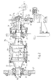
- FIG. 1 shows schematically an embossing machine in which the present invention can be applied
- FIG. 2 shows a side view, in partial longitudinal section, of an embossing cylinder
- FIG. 3 shows in a greatly enlarged longitudinal section one end of the embossing cylinder in a first embodiment
- FIG. 4 shows a view taken on IV-IV as marked in FIG. 3 ;
- FIG. 5 shows a view taken on V-V as marked in FIG. 3 ;
- FIGS. 6 and 7 show two greatly enlarged details of the two opposite ends of the embossing cylinder in a second embodiment.
- FIG. 1 shows in a highly schematic way an embossing machine, indicated in a general way by 1 , in which the present invention can be applied.
- the fundamental principles of the invention are also applicable to the production of embossing cylinders for use in embossing machines of other types, for example “nested” machines or single embossing devices.
- the invention can also be used for the production of cylinders for processing web materials, in order to carry out operations other than embossing, for example printing or other processes which may require the rapid replacement of an interchangeable sleeve fitted on the cylinder, wherever problems of angular slipping between an interchangeable sleeve and the central core of the cylinder occur.
- the embossing machine 1 is of what is known as the tip-to-tip type, and has a first embossing cylinder 3 and a second embossing cylinder 5 , each provided with an interchangeable sleeve.
- the structure of the embossing cylinders is described in detail below.
- the embossing pattern consisting of a plurality of protuberances, is formed on the outer surfaces of the embossing cylinders.
- the embossing cylinders 3 and 5 interact with corresponding pressure rollers 7 and 9 .
- a first ply of web material, indicated by V 1 passes between the pressure roller 7 and the embossing cylinder 3 , and is embossed there.
- the two embossed plies are laminated and joined in the nip between the embossing cylinders 3 and 5 to form the web material N.
- the joining is carried out by means of adhesive applied by an adhesive dispenser 11 .
- FIG. 2 shows one of the two embossing cylinders 3 and 5 . These can be essentially identical to each other, and therefore only one of them, in particular the cylinder 3 , will be illustrated in greater detail. It has a cylindrical central core 13 extending along the axis of the embossing cylinder and supported at its ends by bearings 15 and 17 housed in bushes 19 and 21 . In the illustrated example, the core 13 is formed by two flanged end shanks 13 P, which terminate and support a cylindrical shell 13 M. The two shanks are inserted into the bearings 15 and 17 .
- the bush 21 is mounted directly in a side piece 23 of the embossing machine, while the bush 19 is inserted into a flange 25 fixed to the second side piece 27 of the embossing machine and releasable therefrom.
- the shank 29 of the cylindrical core 13 extends beyond the bearing 17 and on said shank is keyed a pulley 31 which imparts the motion to the embossing cylinder.
- the shank 29 extends beyond the pulley 31 to form an end 29 A which can be engaged by a bracket 33 hinged at 35 to a rod 37 which can be moved vertically by an actuator 39 as shown by the arrow f 37 .
- FIG. 2 shows the two possible positions of the bracket 33 .
- the bracket 33 In the first position, shown in solid lines, the bracket 33 is in a vertical configuration and engages the end 29 A of the shank 29 with a shaped wheel 41 .
- the actuator 39 When the bracket 33 is in this position, the actuator 39 is operated until the bearing contained in the bush 29 is completely released from the weight of the cylinder. At this point, the flange 25 can be removed, and the embossing cylinder 3 can be cantileverly retained by the bearing 17 only, so that the interchangeable sleeve can be replaced by the methods described below.
- the bracket 33 In the position shown in broken lines, the bracket 33 is in a horizontal configuration and the embossing cylinder 3 can rotate about its axis indicated by A-A.
- An interchangeable sleeve indicated in a general way by 45 , is fitted on the core 13 of the embossing cylinder 3 .
- the external diameter of the interchangeable sleeve 45 is smaller than the hole which remains free in the side piece 27 after the flange 25 has been extracted from it.
- the sleeve 45 can be extracted from the cylindrical core 13 and replaced with another by engaging the cylinder 3 with the bracket 33 and removing the flange 25 (so that the cylinder 3 is cantileverly retained).
- the interchangeable sleeve 45 consists of two cylindrical components, which can be seen in particular in the section in FIG. 3 , which shows an enlargement of the detail indicated by III of the right-hand end of the embossing cylinder of FIG. 2 , with the interchangeable sleeve mounted and locked on the internal cylindrical core 13 .
- the components forming the interchangeable sleeve 45 are indicated by 47 and 49 .
- the internal cylindrical component 47 is advantageously made from glass fiber reinforced plastic, in other words with a structure consisting of a helical distribution of glass fibers in a matrix of polymerized resin.
- the cylindrical component 49 consists of a very hard elastomer, for example ebonite or a synthetic elastomer, whose hardness is equivalent and which is in any case suitable for the purposes for which the interchangeable sleeve is intended.
- the number 49 A indicates the protuberances which are formed on the outer surface of the interchangeable sleeve, and which therefore consist of the material forming the outer cylindrical component 49 of said sleeve.
- apertures are provided in the central core 13 so that the interior 13 A of the core 13 communicates with the outer surface of the cylindrical shell 13 M of the core, in other words with the surface on which the interchangeable sleeve 45 slides.
- the numbers 51 indicate in a general way connecting ducts between the inside and the outside of the core 13 of the cylinder 3 .
- the compressed air inside the sleeve 13 is introduced by means of a duct connected to a source of compressed air (not shown) which is connected to a connection 53 formed in the shank 29 .
- the elasticity of the interchangeable sleeve 45 is sufficient to lock said sleeve axially and angularly on the core 13 except in the presence of differential thermal expansion of these two components and/or high tangential forces.
- the dissipation of heat caused by the high pressures between the embossing cylinder 3 and the corresponding pressure roller 7 causes an expansion of the interchangeable sleeve 45 by an amount sufficient to cause a slight angular displacement of said sleeve with respect to the core 13 .
- an end-fitted angular locking system is provided at each end of the embossing cylinder 3 .
- the two systems are essentially identical, and therefore only the right-hand end ( FIG. 2 ) of the embossing cylinder is shown in the drawing.
- at least one bracket 61 is fixed on the end face of the core 13 of the embossing cylinder 3 , by means of screw members 63 which are engaged in holes formed in the thickness of the cylindrical shell 13 M of the cylindrical core 13 .
- a spacer 65 is placed between the end face 13 F of the cylindrical shell 13 M of the core 13 and the bracket 61 . This prevents the axial crushing of the sleeve between the two opposite brackets 61 .
- the bracket 61 extends only over a fraction of the circular extension of the end face of the core 13 , but there is no reason why the bracket 61 should not have an annular shape, and therefore an extension of 360°.
- the bracket 61 has a tooth 61 A parallel to the axis A-A of the embossing cylinder 3 .
- the tooth 61 A is inserted into an edge notch or recess 67 formed in a terminal ring 69 integral with the inner cylindrical component 47 of the interchangeable sleeve 45 .
- the terminal ring 69 is advantageously made from a rigid material, for example steel. It is housed within the overall thickness of the interchangeable sleeve 45 , since the axial length of the outer cylindrical component 49 is smaller than that of the cylindrical component 47 . The difference between the lengths of the two components is approximately equal to twice the axial extension of the ring 69 , since a terminal ring is located on the opposite end (not illustrated) of the interchangeable sleeve 45 .
- the internal diameter of the inner cylindrical component 47 at the position of the rigid ring 69 is slightly greater than that of the rest of the component, to facilitate the fitting of the sleeve 45 in spite of the lack of radial expandability of the sleeve at the position of the ring 69 .
- the interchangeable sleeve 45 can be angularly locked with respect to the core by locking at least one bracket 61 on each of the two ends of the inner core 13 . It is also possible to provide a plurality of end brackets 61 on each end, and/or brackets having more than one tooth 61 A each, to obtain a better distribution of stresses.
- FIGS. 6 and 7 show an enlargement of the two opposite ends of the embossing cylinder 3 in a different embodiment. Identical numbers indicate identical or corresponding parts in the two embodiments.
- brackets provided at the two ends of the embossing cylinder 3 are indicated by 61 and 62 respectively, and their shapes are slightly different from each other, for reasons which are explained below.
- the right-hand end (with reference to the configuration in FIG. 2 ) of the core 13 of the embossing cylinder 3 has an annular shoulder 13 S on which the interchangeable sleeve 45 bears, while the opposite end has no shoulder ( FIG. 7 ), thus enabling the interchangeable sleeve to be fitted and removed.
- the interchangeable sleeve 45 has an end area with a conical surface, indicated by 45 B, on its outer surface.
- the conical surfaces 45 B are tapered towards the corresponding edges of the sleeve.
- Each of the brackets 61 and 62 has a corresponding conical surface, indicated by 61 A and 62 A respectively, whose shape is complementary to that of the surfaces 45 B.
- the conical surfaces 61 A and 61 B can have an extension of 360°, thus covering the whole edge of the sleeve. Alternatively, they can have a smaller extension and take the form of appendages distributed suitably along the circumferential extension of the cylinder.
- the brackets 61 and 62 have an annular extension.
- the bracket 61 is shaped in such a way that it can be centered and guided onto the shoulder 13 S during the tightening movement, while the bracket 62 is shaped to be centered and guided onto the cylindrical surface of smaller diameter 13 T formed on the corresponding end of the core 13 .
- the two brackets 61 and 62 could have a partial extension instead of a full annular extension. In this case they will be guided and centered also onto the inner edge of the shell 13 M.
Landscapes
- Engineering & Computer Science (AREA)
- Mechanical Engineering (AREA)
- General Engineering & Computer Science (AREA)
- Machines For Manufacturing Corrugated Board In Mechanical Paper-Making Processes (AREA)
- Treatment Of Fiber Materials (AREA)
- Absorbent Articles And Supports Therefor (AREA)
- Packaging Of Annular Or Rod-Shaped Articles, Wearing Apparel, Cassettes, Or The Like (AREA)
- Treatments For Attaching Organic Compounds To Fibrous Goods (AREA)
- Mechanical Coupling Of Light Guides (AREA)
- Forms Removed On Construction Sites Or Auxiliary Members Thereof (AREA)
- Shaping Of Tube Ends By Bending Or Straightening (AREA)
- Gloves (AREA)
Applications Claiming Priority (4)
| Application Number | Priority Date | Filing Date | Title |
|---|---|---|---|
| ITFI2001A0223 | 2001-11-23 | ||
| ITFI2001A000223 | 2001-11-26 | ||
| IT2001FI000223A ITFI20010223A1 (it) | 2001-11-26 | 2001-11-26 | Cilindro goffratore con camicia intercambiabile e con sistema di bloccaggio frontale della camicia, e gruppo goffratore comprendente detto |
| PCT/IT2002/000733 WO2003045679A1 (en) | 2001-11-26 | 2002-11-20 | Embossing cylinder with interchangeable sleeve and with system for locking the sleeve at the ends, and embossing machine comprising said cylinder |
Publications (2)
| Publication Number | Publication Date |
|---|---|
| US20050020422A1 US20050020422A1 (en) | 2005-01-27 |
| US7322917B2 true US7322917B2 (en) | 2008-01-29 |
Family
ID=11442298
Family Applications (1)
| Application Number | Title | Priority Date | Filing Date |
|---|---|---|---|
| US10/496,152 Expired - Fee Related US7322917B2 (en) | 2001-11-23 | 2002-11-20 | Embossing cylinder with interchangeable sleeve and with system for locking the sleeve at the ends and embossing machine comprising said cylinder |
Country Status (11)
| Country | Link |
|---|---|
| US (1) | US7322917B2 (de) |
| EP (1) | EP1448364B1 (de) |
| JP (1) | JP2005510381A (de) |
| AT (1) | ATE302113T1 (de) |
| AU (1) | AU2002358979A1 (de) |
| BR (1) | BR0214413A (de) |
| DE (1) | DE60205652T2 (de) |
| DK (1) | DK1448364T3 (de) |
| ES (1) | ES2243787T3 (de) |
| IT (1) | ITFI20010223A1 (de) |
| WO (1) | WO2003045679A1 (de) |
Cited By (3)
| Publication number | Priority date | Publication date | Assignee | Title |
|---|---|---|---|---|
| US20080051275A1 (en) * | 2006-08-14 | 2008-02-28 | Eastman Kodak Company | Double sleeved electrophotographic member |
| US20090114347A1 (en) * | 2006-03-15 | 2009-05-07 | Fabio Perini S.P. A. | Embossing Roller And Method For The Manufacturing Thereof |
| US9341213B2 (en) * | 2012-10-19 | 2016-05-17 | Frc Holding Corp. | Quick release roller sleeve mounting hub |
Families Citing this family (7)
| Publication number | Priority date | Publication date | Assignee | Title |
|---|---|---|---|---|
| ITFI20010223A1 (it) * | 2001-11-26 | 2003-05-26 | Perini Fabio Spa | Cilindro goffratore con camicia intercambiabile e con sistema di bloccaggio frontale della camicia, e gruppo goffratore comprendente detto |
| US7383768B2 (en) * | 2004-05-05 | 2008-06-10 | Awi Licensing Company | Rapid prototyping and filling commercial pipeline |
| ITFI20040107A1 (it) | 2004-05-05 | 2004-08-05 | Perini Fabio Spa | Rullo a camicia intercambiabile per gruppi goffratori e gruppo goffratore comprendente tale rullo |
| ITFI20040202A1 (it) | 2004-09-30 | 2004-12-30 | Perini Fabio Spa | Camicia intercambiabile per rulli goffratori o simili, metodo per la sua realizzazione, e rullo comprendente detta camicia |
| ITBO20040652A1 (it) * | 2004-10-21 | 2005-01-21 | Gd Spa | Unita' per goffratura e metodo per la sua realizzazione |
| US7882869B2 (en) * | 2007-01-26 | 2011-02-08 | Nicholson Manufacturing Ltd. | Replaceable flute inserts for a roller assembly of a debarker apparatus |
| CN217172653U (zh) * | 2022-03-09 | 2022-08-12 | 宁德时代新能源科技股份有限公司 | 输送系统及电池生产系统 |
Citations (28)
| Publication number | Priority date | Publication date | Assignee | Title |
|---|---|---|---|---|
| US2005885A (en) * | 1932-01-23 | 1935-06-25 | Westinghouse Electric & Mfg Co | Roll |
| US2658262A (en) * | 1951-04-04 | 1953-11-10 | Andre Rubber Co | Rubber roller |
| US3739722A (en) | 1971-08-13 | 1973-06-19 | Gross Instr Co | Print roll and mounting means |
| US4003114A (en) | 1976-02-25 | 1977-01-18 | Armstrong Cork Company | Compressible sleeve embossing roll |
| US4007680A (en) * | 1974-07-03 | 1977-02-15 | Pfleger Frank G | Gravure printing cylinders |
| US4044678A (en) * | 1975-07-14 | 1977-08-30 | Schublich A/S | Printing cylinder for printing machines |
| US4144813A (en) | 1976-01-08 | 1979-03-20 | Strachan & Henshaw Limited | Printing sleeves |
| US4150622A (en) * | 1976-09-13 | 1979-04-24 | Reinhard Muhs | Printing roller |
| EP0181726A2 (de) | 1984-10-29 | 1986-05-21 | Drg (Uk) Limited | Druckzylinder mit einem abnehmbaren Mantel |
| US4716637A (en) * | 1982-07-29 | 1988-01-05 | The B. F. Goodrich Company | Spreader roll |
| US4782568A (en) * | 1986-02-21 | 1988-11-08 | Oy Tampella Ab | Press roll |
| US4800644A (en) * | 1983-02-18 | 1989-01-31 | Ralph Muellenberg | Method for fastening or loosening a clamp unit |
| EP0009360B2 (de) | 1978-09-13 | 1991-03-20 | Drg (Uk) Limited | Herstellung von Hohlkörpern für die Druckerei |
| US5096527A (en) | 1988-11-23 | 1992-03-17 | Fabio Perini S.P.A. | Process and apparatus for embossing with cylinders having protrusions inclined in two directions |
| JPH06280855A (ja) * | 1993-03-23 | 1994-10-07 | Canon Inc | 円筒部材 |
| US5490458A (en) * | 1994-04-13 | 1996-02-13 | Bryce Corporation | Printing press cylinder assembly |
| EP0836928A1 (de) | 1996-10-16 | 1998-04-22 | James River Corporation Of Virginia | Prägevorrichtung mit einer Umhüllung versehenen Prägerolle |
| US5904095A (en) | 1997-03-19 | 1999-05-18 | Meca Of Green Bay, Inc. | Bridge mandrel for flexographic printing presses |
| WO1999044814A1 (en) | 1998-03-02 | 1999-09-10 | Fabio Perini S.P.A. | Method and device for producing an embossed web material and product made in this way |
| US6053232A (en) | 1995-12-05 | 2000-04-25 | Fabio Perini, S.P.A. | Embossing and laminating machine with embossing cylinders having different rotational speed |
| US20020040651A1 (en) * | 1999-11-22 | 2002-04-11 | Mceachern David A. | Mounting printing plate cylinder having tapered bore to untapered rotatable drive shaft |
| US6394943B1 (en) * | 2000-05-19 | 2002-05-28 | Steven Cormier | Image transfer drum for document printer/copier |
| US6436022B1 (en) * | 1995-04-10 | 2002-08-20 | Schwabische Huttenewerke Gmbh | Roll adjustable in shape |
| US6620084B2 (en) * | 2000-10-04 | 2003-09-16 | Yesuvius Crucible Company | Conveyor roll end cap |
| US20040242392A1 (en) * | 2001-11-26 | 2004-12-02 | Giulio Betti | Cylinder with interchangeable sleeve method of manufacturing the same and associated unit |
| US20040255804A1 (en) * | 2003-01-31 | 2004-12-23 | Giesecke & Devrient Gmbh | Mounting cylinder for mounting cylindrical embossing tools for embossing rolls |
| US20050020422A1 (en) * | 2001-11-23 | 2005-01-27 | Giulio Betti | Embossing cylinder with interchangeable sleeve and with system for locking the sleeve at the ends and embossing machine comprising said cylinder |
| US20070015648A1 (en) * | 2003-05-15 | 2007-01-18 | Gugliemo Biagiotti | Variable crown roller for devices for processing continuous web material and device comprising said roller |
-
2001
- 2001-11-26 IT IT2001FI000223A patent/ITFI20010223A1/it unknown
-
2002
- 2002-11-20 ES ES02793325T patent/ES2243787T3/es not_active Expired - Lifetime
- 2002-11-20 US US10/496,152 patent/US7322917B2/en not_active Expired - Fee Related
- 2002-11-20 BR BR0214413-1A patent/BR0214413A/pt not_active Application Discontinuation
- 2002-11-20 DK DK02793325T patent/DK1448364T3/da active
- 2002-11-20 JP JP2003547160A patent/JP2005510381A/ja active Pending
- 2002-11-20 EP EP02793325A patent/EP1448364B1/de not_active Expired - Lifetime
- 2002-11-20 WO PCT/IT2002/000733 patent/WO2003045679A1/en not_active Ceased
- 2002-11-20 DE DE60205652T patent/DE60205652T2/de not_active Expired - Lifetime
- 2002-11-20 AU AU2002358979A patent/AU2002358979A1/en not_active Abandoned
- 2002-11-20 AT AT02793325T patent/ATE302113T1/de not_active IP Right Cessation
Patent Citations (30)
| Publication number | Priority date | Publication date | Assignee | Title |
|---|---|---|---|---|
| US2005885A (en) * | 1932-01-23 | 1935-06-25 | Westinghouse Electric & Mfg Co | Roll |
| US2658262A (en) * | 1951-04-04 | 1953-11-10 | Andre Rubber Co | Rubber roller |
| US3739722A (en) | 1971-08-13 | 1973-06-19 | Gross Instr Co | Print roll and mounting means |
| US4007680A (en) * | 1974-07-03 | 1977-02-15 | Pfleger Frank G | Gravure printing cylinders |
| US4044678A (en) * | 1975-07-14 | 1977-08-30 | Schublich A/S | Printing cylinder for printing machines |
| US4144813A (en) | 1976-01-08 | 1979-03-20 | Strachan & Henshaw Limited | Printing sleeves |
| US4003114A (en) | 1976-02-25 | 1977-01-18 | Armstrong Cork Company | Compressible sleeve embossing roll |
| US4150622A (en) * | 1976-09-13 | 1979-04-24 | Reinhard Muhs | Printing roller |
| EP0009360B2 (de) | 1978-09-13 | 1991-03-20 | Drg (Uk) Limited | Herstellung von Hohlkörpern für die Druckerei |
| US4716637A (en) * | 1982-07-29 | 1988-01-05 | The B. F. Goodrich Company | Spreader roll |
| US4800644A (en) * | 1983-02-18 | 1989-01-31 | Ralph Muellenberg | Method for fastening or loosening a clamp unit |
| EP0181726A2 (de) | 1984-10-29 | 1986-05-21 | Drg (Uk) Limited | Druckzylinder mit einem abnehmbaren Mantel |
| EP0181726A3 (en) | 1984-10-29 | 1987-09-16 | Drg (Uk) Limited | Printing roll with detachable sleeve |
| US4782568A (en) * | 1986-02-21 | 1988-11-08 | Oy Tampella Ab | Press roll |
| US5096527A (en) | 1988-11-23 | 1992-03-17 | Fabio Perini S.P.A. | Process and apparatus for embossing with cylinders having protrusions inclined in two directions |
| JPH06280855A (ja) * | 1993-03-23 | 1994-10-07 | Canon Inc | 円筒部材 |
| US5490458A (en) * | 1994-04-13 | 1996-02-13 | Bryce Corporation | Printing press cylinder assembly |
| US6436022B1 (en) * | 1995-04-10 | 2002-08-20 | Schwabische Huttenewerke Gmbh | Roll adjustable in shape |
| US6053232A (en) | 1995-12-05 | 2000-04-25 | Fabio Perini, S.P.A. | Embossing and laminating machine with embossing cylinders having different rotational speed |
| EP0836928A1 (de) | 1996-10-16 | 1998-04-22 | James River Corporation Of Virginia | Prägevorrichtung mit einer Umhüllung versehenen Prägerolle |
| US5904095A (en) | 1997-03-19 | 1999-05-18 | Meca Of Green Bay, Inc. | Bridge mandrel for flexographic printing presses |
| WO1999044814A1 (en) | 1998-03-02 | 1999-09-10 | Fabio Perini S.P.A. | Method and device for producing an embossed web material and product made in this way |
| US20020040651A1 (en) * | 1999-11-22 | 2002-04-11 | Mceachern David A. | Mounting printing plate cylinder having tapered bore to untapered rotatable drive shaft |
| US6394943B1 (en) * | 2000-05-19 | 2002-05-28 | Steven Cormier | Image transfer drum for document printer/copier |
| US6620084B2 (en) * | 2000-10-04 | 2003-09-16 | Yesuvius Crucible Company | Conveyor roll end cap |
| US20050020422A1 (en) * | 2001-11-23 | 2005-01-27 | Giulio Betti | Embossing cylinder with interchangeable sleeve and with system for locking the sleeve at the ends and embossing machine comprising said cylinder |
| US20040242392A1 (en) * | 2001-11-26 | 2004-12-02 | Giulio Betti | Cylinder with interchangeable sleeve method of manufacturing the same and associated unit |
| US20040255804A1 (en) * | 2003-01-31 | 2004-12-23 | Giesecke & Devrient Gmbh | Mounting cylinder for mounting cylindrical embossing tools for embossing rolls |
| US6874415B2 (en) * | 2003-01-31 | 2005-04-05 | Giesecke & Devrient Gmbh | Mounting cylinder for mounting cylindrical embossing tools for embossing rolls |
| US20070015648A1 (en) * | 2003-05-15 | 2007-01-18 | Gugliemo Biagiotti | Variable crown roller for devices for processing continuous web material and device comprising said roller |
Cited By (5)
| Publication number | Priority date | Publication date | Assignee | Title |
|---|---|---|---|---|
| US20090114347A1 (en) * | 2006-03-15 | 2009-05-07 | Fabio Perini S.P. A. | Embossing Roller And Method For The Manufacturing Thereof |
| US8973267B2 (en) * | 2006-03-15 | 2015-03-10 | Fabio Perini, S.P.A. | Embossing roller and method for the manufacturing thereof |
| US20080051275A1 (en) * | 2006-08-14 | 2008-02-28 | Eastman Kodak Company | Double sleeved electrophotographic member |
| US7892160B2 (en) * | 2006-08-14 | 2011-02-22 | Eastman Kodak Company | Double sleeved electrophotographic member |
| US9341213B2 (en) * | 2012-10-19 | 2016-05-17 | Frc Holding Corp. | Quick release roller sleeve mounting hub |
Also Published As
| Publication number | Publication date |
|---|---|
| BR0214413A (pt) | 2004-09-14 |
| DE60205652D1 (de) | 2005-09-22 |
| AU2002358979A1 (en) | 2003-06-10 |
| US20050020422A1 (en) | 2005-01-27 |
| ES2243787T3 (es) | 2005-12-01 |
| DE60205652T2 (de) | 2006-06-08 |
| DK1448364T3 (da) | 2005-09-19 |
| ATE302113T1 (de) | 2005-09-15 |
| EP1448364B1 (de) | 2005-08-17 |
| WO2003045679A1 (en) | 2003-06-05 |
| JP2005510381A (ja) | 2005-04-21 |
| EP1448364A1 (de) | 2004-08-25 |
| ITFI20010223A1 (it) | 2003-05-26 |
Similar Documents
| Publication | Publication Date | Title |
|---|---|---|
| US7322917B2 (en) | Embossing cylinder with interchangeable sleeve and with system for locking the sleeve at the ends and embossing machine comprising said cylinder | |
| US7357892B2 (en) | Method of manufacturing cylinder with interchangeable sleeve | |
| US20100307704A1 (en) | Apparatus and method for degrading a web in the machine direction while preserving cross-machine direction strength | |
| EP1744873B1 (de) | Rolle mit austauschbarer hülle für prägeanlagen und prägeanlagen mit dieser rolle | |
| US5189935A (en) | Rotary cutting die assembly | |
| US20100181040A1 (en) | Device for treating paper webs | |
| US10737456B2 (en) | Pressing roller for the processing of web paper material | |
| EP1622757B1 (de) | Variable kronenwalze für vorrichtungen zur bearbeitung von endlosbahnmaterial und die walze umfassende vorrichtung | |
| EP1799433B1 (de) | Austauschbare hülse zum prägen von rollen und ähnlichem, herstellungsverfahren dafür und rolle mit besagter hülse | |
| EP1836045B1 (de) | Prägevorrichtung mit prägewalze, die aus einer austauschbaren hülse und stützkernen besteht | |
| EP2974857B1 (de) | Präge-/laminierwalze | |
| US7971529B2 (en) | Assembly for rotary press | |
| EP1820636B1 (de) | Prägeeinheit mit mehreren Druckwalzen | |
| CN221187935U (zh) | 一种可快速替换辊套的多花型辊 | |
| EP3009385A2 (de) | Walze zur verarbeitung eines durchgehenden bahnmaterials und vorrichtung mit der besagten walze | |
| US20080276814A1 (en) | Web press and method for producing the press | |
| WO2009060274A2 (en) | Cylinder for offset printing machines provided with abutment rings | |
| US20020003972A1 (en) | Device for positioning a cylinder sleeve on a supporting body | |
| US20090052816A1 (en) | Wear pads for head yoke plates | |
| EP0896865A1 (de) | Abstreifer mit Stiften |
Legal Events
| Date | Code | Title | Description |
|---|---|---|---|
| AS | Assignment |
Owner name: FABIO PERINI S.P.A., ITALY Free format text: ASSIGNMENT OF ASSIGNORS INTEREST;ASSIGNORS:BETTI, GIULIO;LORENZI, FABRIZIO;DI NARDO, WALTER;REEL/FRAME:019863/0941 Effective date: 20020717 |
|
| FPAY | Fee payment |
Year of fee payment: 4 |
|
| REMI | Maintenance fee reminder mailed | ||
| LAPS | Lapse for failure to pay maintenance fees | ||
| STCH | Information on status: patent discontinuation |
Free format text: PATENT EXPIRED DUE TO NONPAYMENT OF MAINTENANCE FEES UNDER 37 CFR 1.362 |
|
| STCH | Information on status: patent discontinuation |
Free format text: PATENT EXPIRED DUE TO NONPAYMENT OF MAINTENANCE FEES UNDER 37 CFR 1.362 |
|
| FP | Lapsed due to failure to pay maintenance fee |
Effective date: 20160129 |