US7475769B2 - Device for handling packets - Google Patents
Device for handling packets Download PDFInfo
- Publication number
- US7475769B2 US7475769B2 US11/488,088 US48808806A US7475769B2 US 7475769 B2 US7475769 B2 US 7475769B2 US 48808806 A US48808806 A US 48808806A US 7475769 B2 US7475769 B2 US 7475769B2
- Authority
- US
- United States
- Prior art keywords
- packets
- transfer unit
- conveyor assembly
- packet
- conveyor
- Prior art date
- Legal status (The legal status is an assumption and is not a legal conclusion. Google has not performed a legal analysis and makes no representation as to the accuracy of the status listed.)
- Expired - Fee Related, expires
Links
Images


Classifications
-
- B—PERFORMING OPERATIONS; TRANSPORTING
- B65—CONVEYING; PACKING; STORING; HANDLING THIN OR FILAMENTARY MATERIAL
- B65G—TRANSPORT OR STORAGE DEVICES, e.g. CONVEYORS FOR LOADING OR TIPPING, SHOP CONVEYOR SYSTEMS OR PNEUMATIC TUBE CONVEYORS
- B65G47/00—Article or material-handling devices associated with conveyors; Methods employing such devices
- B65G47/22—Devices influencing the relative position or the attitude of articles during transit by conveyors
- B65G47/26—Devices influencing the relative position or the attitude of articles during transit by conveyors arranging the articles, e.g. varying spacing between individual articles
- B65G47/30—Devices influencing the relative position or the attitude of articles during transit by conveyors arranging the articles, e.g. varying spacing between individual articles during transit by a series of conveyors
- B65G47/32—Applications of transfer devices
-
- B—PERFORMING OPERATIONS; TRANSPORTING
- B65—CONVEYING; PACKING; STORING; HANDLING THIN OR FILAMENTARY MATERIAL
- B65G—TRANSPORT OR STORAGE DEVICES, e.g. CONVEYORS FOR LOADING OR TIPPING, SHOP CONVEYOR SYSTEMS OR PNEUMATIC TUBE CONVEYORS
- B65G47/00—Article or material-handling devices associated with conveyors; Methods employing such devices
- B65G47/74—Feeding, transfer, or discharging devices of particular kinds or types
- B65G47/84—Star-shaped wheels or devices having endless travelling belts or chains, the wheels or devices being equipped with article-engaging elements
- B65G47/841—Devices having endless travelling belts or chains equipped with article-engaging elements
-
- B—PERFORMING OPERATIONS; TRANSPORTING
- B65—CONVEYING; PACKING; STORING; HANDLING THIN OR FILAMENTARY MATERIAL
- B65G—TRANSPORT OR STORAGE DEVICES, e.g. CONVEYORS FOR LOADING OR TIPPING, SHOP CONVEYOR SYSTEMS OR PNEUMATIC TUBE CONVEYORS
- B65G2201/00—Indexing codes relating to handling devices, e.g. conveyors, characterised by the type of product or load being conveyed or handled
- B65G2201/02—Articles
- B65G2201/0235—Containers
- B65G2201/025—Boxes
-
- B—PERFORMING OPERATIONS; TRANSPORTING
- B65—CONVEYING; PACKING; STORING; HANDLING THIN OR FILAMENTARY MATERIAL
- B65G—TRANSPORT OR STORAGE DEVICES, e.g. CONVEYORS FOR LOADING OR TIPPING, SHOP CONVEYOR SYSTEMS OR PNEUMATIC TUBE CONVEYORS
- B65G2203/00—Indexing code relating to control or detection of the articles or the load carriers during conveying
- B65G2203/02—Control or detection
- B65G2203/0208—Control or detection relating to the transported articles
- B65G2203/025—Speed of the article
Definitions
- the present invention relates to a device for handling packets.
- the present invention may be used to advantage in the packing of cigarettes, to which the following description refers purely by way of example.
- the present invention relates to a device for handling packets comprising a conveyor assembly for conveying a line of packets.
- the conveyor assembly feeds the packets to an intermediate station.
- the device also comprises a transfer unit; and a support assembly located at the intermediate station to support the packets coming off the conveyor assembly.
- the packets coming off the conveyor assembly are pushed to the transfer unit by the line of packets travelling on the conveyor assembly; and the transfer unit transfers the packets coming off the conveyor assembly from an extraction location at the intermediate station to an output conveyor.
- the conveyor assembly conveys the line of packets at a given travelling speed in a first direction.
- the device also comprises a feed unit for feeding a succession of packets to the conveyor assembly in the first direction; in actual use, once fed to the conveyor assembly, the incoming packets form part of the line of packets; and the packets forming part of the line of packets are conveyed by the conveyor assembly.
- a drawback of known devices of this type is the possibility of gaps forming between successive packets in the lines of packets moving forward from the input station. As a result, the packets are subject to damage, by being allowed too much freedom of movement, and/or have different structural characteristics as a result of different pressure being exerted on the walls of the packets.
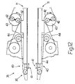
- FIG. 1 shows a schematic view in perspective, with parts removed for clarity, of a device in accordance with the present invention
- FIGS. 2 to 7 show side views of a detail of the FIG. 1 device in different operating positions
- FIG. 8 shows a top plan view, with parts removed for clarity, of the FIG. 2-7 detail in the FIG. 3 operating position;
- FIG. 9 shows a partly sectioned side view of a further detail of the FIG. 1 device
- FIGS. 10 and 11 show top plan views, with parts removed for clarity, of the FIG. 9 detail
- FIG. 12 shows a detail of FIG. 1 with certain parts highlighted.
- Number 1 in FIG. 1 indicates as a whole a device for handling packets 2 , in particular of cigarettes (not shown).
- Device 1 comprises two drying beams 3 , 3 ′ for stabilizing and conveying packets 2 from an input station 4 to an intermediate station 5 , where two transfer units 6 , 6 ′, one for each drying beam 3 , 3 ′, pick up and feed packets 2 to a single output conveyor 7 .
- Each packet 2 is substantially parallelepiped-shaped with two parallel major lateral walls 8 (only one of which is shown in FIG. 1 ).
- each drying beam 3 , 3 ′ transfers heat to glue (not shown) on packets 2 to dry the glue and stabilize packets 2 , and comprises a respective conveyor assembly 9 , 9 ′, and a number of heating plates (not shown).
- Conveyor assemblies 9 , 9 ′ convey respective lines 10 of packets 2 in a direction A along respective paths P 1 , P 2 , and each comprise a respective pair of parallel, facing belt conveyors 11 , and a respective drive (not shown).
- Paths P 1 , P 2 are substantially horizontal, and are arranged substantially parallel and one over the other.
- packets 2 are fed parallel to themselves along paths P 1 , P 2 , with walls 8 substantially perpendicular to direction A; and successive packets 2 in lines 10 are normally positioned contacting one another.
- Device 1 also comprises a feed unit 12 for feeding packets 2 successively to drying beams 3 , 3 ′ at input station 4 .
- Feed unit 12 comprises a known lift (not shown) for bringing the end packets 2 of a single line (not shown) of packets 2 —extending horizontally upstream from input station 4 , at a higher level than conveyor assembly 9 ′ and at a lower level than conveyor assembly 9 —individually and alternately onto a level with conveyor assemblies 9 and 9 ′.
- Conveyor assemblies 9 , 9 ′ and other portions of device 1 at input station 4 and intermediate station 5 up- and downstream from conveyor assemblies 9 , 9 ′ operate in substantially the same way and are structurally substantially identical. For the sake of simplicity, therefore, only the structure and operation of conveyor assembly 9 and the portions of device 1 at input station 4 and intermediate station 5 up- and downstream from conveyor assembly 9 are described below; it being understood that, unless otherwise stated, the same description also applies to conveyor assembly 9 ′ and the portions of device 1 at input station 4 and intermediate station 5 up- and downstream from conveyor assembly 9 ′.
- feed unit 12 comprises a pusher 13 located upstream from conveyor assembly 9 , and which pushes packets 2 successively and horizontally in direction A to conveyors 11 .
- Feed unit 12 also comprises a supporting member 14 , on which packets 2 slide in use. More specifically, a line 15 of packets 2 is formed on supporting member 14 , and is fed forward in steps by a back-and-forth movement of pusher 13 in direction A.
- a line 15 of packets 2 is formed on supporting member 14 , and is fed forward in steps by a back-and-forth movement of pusher 13 in direction A.
- conveyors 11 grip packet 2 a, which then becomes part of line 10 .
- packet 2 a is fed forward in direction A by conveyors 11 .
- Device 1 also comprises a reject unit 16 for rejecting flawed packets 2 , and which comprises a pusher 17 for removing flawed packets 2 from input station 4 by pushing the flawed packets 2 , in a horizontal direction B crosswise to direction A, into an output chute 18 .
- Reject unit 16 also comprises a detector 19 located at input station 4 to detect any flaws in packets 2 . In further embodiments not shown, detector 19 may be located elsewhere, e.g. upstream from input station 4 .
- Device 1 also comprises a control unit 20 , which is connected to transfer units 6 , 6 ′, to conveyor assemblies 9 , 9 ′, to detector 19 , and to pusher 17 , and which activates pusher 17 as a function of the findings of detector 19 .
- Control unit 20 also regulates operation of conveyor assemblies 9 , 9 ′ to adjust the travelling speed V 1 of lines 10 in direction A. More specifically, control unit 20 regulates the drives (not shown) of conveyors 9 , 9 ′ independently of each other.
- a gap 21 ( FIG. 3 ) is created by line 10 of packets 2 (in particular, packets 2 a and 2 c ) moving forward in direction A, and by the stalling of line 15 of packets 2 (in particular, incoming packets 2 d ).
- control unit 20 reduces travelling speed V 1 , and further packets 2 (in particular, incoming packets 2 e ) are pushed forward by pusher 13 in direction A to close gap 21 ( FIGS. 4 to 7 ).
- incoming packets 2 d and 2 e are fed forward in direction A faster than line 10 .
- a continuous line 10 is thus achieved, with the following advantages:
- device 1 also comprises a support assembly 22 located at intermediate station 5 , between conveyor assembly 9 and transfer unit 6 , to support an orderly group 23 of packets 2 coming off conveyor assembly 9 .
- support assembly 22 has a slide surface, on which orderly group 23 travels, in use, in direction A to transfer unit 6 .
- Orderly group 23 comprises a number of packets 2 arranged in a line extending between conveyor assembly 9 and transfer unit 6 ; successive packets 2 in orderly group 23 are positioned contacting one another; and, in actual use, at the intermediate station, orderly group 23 is pushed in direction A to transfer unit 6 by line 10 travelling on conveyor assembly 9 .
- Device 1 also comprises a detector 24 located at intermediate station 5 , connected to control unit 20 , and for determining the location of an end packet 2 in orderly group 23 . More specifically, detector 24 determines the presence of packet 2 ′ at a given location L at intermediate station 5 . Location L is located immediately upstream from an extraction location E, from which transfer unit 6 removes packet 2 ′.
- Control unit 20 regulates operation of conveyor assembly 9 to adjust travelling speed V 1 as a function of a machine angle of transfer unit 6 and the findings of detector 24 .
- control unit 20 reduces travelling speed V 1 ; and, conversely, when packet 2 ′ is detected at location L after the reference machine angle of transfer unit 6 , control unit 20 increases travelling speed V 1 .
- control unit 20 determines a time difference between the presence of packet 2 ′ at location L and the reference machine angle, and compares it with a threshold difference.
- the variation in travelling speed V 1 by control unit 20 is quantitatively independent of the time difference; the variation in travelling speed V 1 is quantitatively dependent on the time difference; the variation in travelling speed V 1 is spread over a number of operating cycles (i.e. over a number of transfer operations of packets 2 ′ to extraction location E).
- control unit 20 may be self-taught and adjust, for example, the reference machine angle.
- Device 1 also comprises an indicator unit 25 ( FIG. 1 ) connected to control unit 20 to indicate the time difference to the operator. More specifically, the indicator unit comprises two green light elements (LEDs) 26 , which light up in the presence of a relatively small time difference; two yellow luminous elements 27 , which light up in the presence of a medium time difference; and two red light elements 28 , which light up in the presence of a relatively large time difference.
- LEDs green light elements
- Transfer unit 6 comprises a number of ejector paddles 29 ( FIGS. 1 , 10 , 11 ) fitted integrally to a belt 30 running about two idle pulleys 31 and a drive pulley 32 .
- each paddle 29 removes a respective packet 2 ′ from intermediate station 5 in a direction C crosswise to direction A, and pushes packet 2 ′ along a given path P 3 from intermediate station 5 to output conveyor 7 .
- Transfer unit 6 also comprises a channel (not shown) extending along path P 3 and for guiding packet 2 ′ along path P 3 .
- transfer unit 6 ′ comprises a number of ejector paddles 29 ′ fitted integrally to a belt 30 ′ running about two idle pulleys 31 ′ and pulley 32 .
- each paddle 29 ′ removes a respective packet 2 ′ from intermediate station 5 in direction C, and pushes packet 2 ′ along a given path P 4 from intermediate station 5 to output conveyor 7 .
- Transfer unit 6 ′ also comprises a channel (not shown) extending along path P 4 and for guiding packet 2 ′ along path P 4 .
- Output conveyor 7 comprises a number of push paddles 33 fitted integrally to a belt 34 running about an idle pulley (not shown) and pulley 32 .
- paths P 3 and P 4 converge towards output conveyor 7 , and transfer units 6 , 6 ′ and output conveyor 7 operate in phase (belts 30 , 30 ′ and 34 are all wound about the same pulley 32 ).
- Detectors 24 are located with respect to transfer units 6 , 6 ′ ( FIG. 9 ) so that, in use, detectors 24 detect the presence of packets 2 ′ immediately upstream from and on a level with paddles 29 , 29 ′ at intermediate station 5 .
- machine angle as used herein is intended to mean a given point in the operating cycle, in which transfer unit 6 assumes a given operating configuration (in particular, the position of paddles 29 ) typical of that point.
- transfer unit 6 operates at constant speed, identical machine angles of successive operating cycles follow one another at constant time intervals of the same duration as the operating cycle.
- Adjusting unit 35 for adjusting the distances between the output ends 36 of conveyor assemblies 9 , 9 ′ and relative extraction locations E.
- Adjusting unit 35 comprises a frame T, to which output conveyor 7 and transfer units 6 , 6 ′ (in particular, pulleys 31 , 31 ′, 32 ) are fitted integrally; and frame T is mounted to oscillate about an axis 37 by means of a hinge 38 .
- an operator may adjust the distances between output ends 36 of conveyor assemblies 9 , 9 ′ and relative extraction locations E by rotating frame T about axis 37 and fixing frame T in the desired position by means of locking devices (not shown).
- Device 1 also comprises a detector (encoder, not shown) connected to control unit 20 to ensure rotation of frame T actually corresponds to the desired adjustment in the distances between output ends 36 and relative extraction locations E.
- a detector encoder, not shown
- control unit 20 indicates to the operator the adjustments to be made by means of an interface 39 (e.g. a screen and a keyboard and/or pushbutton panel and/or pointing device), and checks the correct adjustments have been made.
- the adjustments depend on the characteristics of the specific type of packet 2 (e.g. size and/or type of packing material).
- Adjusting unit 35 also comprises an extension device 40 for extending a respective conveyor 11 towards respective extraction location E.
- FIG. 12 shows one possible embodiment of respective end portions of two of conveyors 11 , in which adjusting unit 35 comprises a worm and a pin (not shown) by which to extend a portion 41 of a respective conveyor 11 .
- Each conveyor 11 also comprises two pulleys 42 fitted to a respective revolving platform 43 ; and a respective belt 44 running about pulleys 42 .
- platforms 43 are rotated to maintain a substantially constant tension of belts 44 .
- Device 1 also comprises a sensor 45 for determining the position of paddles 29 ′, and which is used by control unit 20 to determine the machine angle of transfer units 6 , 6 ′, particularly when starting up device 1 .
- Device 1 is therefore extremely versatile, by adapting easily to different types of packets 2 , and—extremely important—reduces the risk of jamming at intermediate station 5 , caused by incorrect positioning of packet 2 ′ at intermediate station 5 and, hence, poor coordination of transfer units 6 , 6 ′ and conveyor assemblies 9 , 9 ′.
Landscapes
- Engineering & Computer Science (AREA)
- Mechanical Engineering (AREA)
- Attitude Control For Articles On Conveyors (AREA)
- Wrapping Of Specific Fragile Articles (AREA)
- Feeding Of Articles To Conveyors (AREA)
Applications Claiming Priority (2)
| Application Number | Priority Date | Filing Date | Title |
|---|---|---|---|
| IT000479A ITBO20050479A1 (it) | 2005-07-19 | 2005-07-19 | Dispositivo per la gestione di pacchetti |
| ITBO2005A000479 | 2005-07-19 |
Publications (2)
| Publication Number | Publication Date |
|---|---|
| US20070045084A1 US20070045084A1 (en) | 2007-03-01 |
| US7475769B2 true US7475769B2 (en) | 2009-01-13 |
Family
ID=37075028
Family Applications (1)
| Application Number | Title | Priority Date | Filing Date |
|---|---|---|---|
| US11/488,088 Expired - Fee Related US7475769B2 (en) | 2005-07-19 | 2006-07-18 | Device for handling packets |
Country Status (5)
| Country | Link |
|---|---|
| US (1) | US7475769B2 (de) |
| EP (1) | EP1746055A3 (de) |
| JP (1) | JP2007022814A (de) |
| CN (1) | CN1915750A (de) |
| IT (1) | ITBO20050479A1 (de) |
Families Citing this family (6)
| Publication number | Priority date | Publication date | Assignee | Title |
|---|---|---|---|---|
| CN102530521A (zh) * | 2010-12-30 | 2012-07-04 | 中国海洋石油总公司 | 步进式管道排队装置 |
| CN104477564A (zh) * | 2014-12-07 | 2015-04-01 | 常州市武进亚太机电配件有限公司 | 传送带 |
| CN109533898B (zh) * | 2019-01-15 | 2020-06-23 | 吉林大学 | 一种输液瓶胶塞生产排布装置 |
| CN110992591B (zh) * | 2019-11-22 | 2021-11-02 | 广东智源机器人科技有限公司 | 自动售卖机 |
| CN114988022B (zh) * | 2022-05-20 | 2023-10-03 | 国家能源集团煤焦化有限责任公司 | 一种双驱动刮板输送机 |
| CN116853767B (zh) * | 2023-06-06 | 2025-07-04 | 无锡先导智能装备股份有限公司 | 一种物料输送方法及物料输送设备 |
Citations (11)
| Publication number | Priority date | Publication date | Assignee | Title |
|---|---|---|---|---|
| US1980411A (en) | 1930-12-11 | 1934-11-13 | Standard Knapp Corp | Article-collecting device |
| US3368766A (en) * | 1965-08-06 | 1968-02-13 | Barber Colman Co | Automatic bobbin handling and spooler loading mechanism |
| US3794154A (en) * | 1972-12-01 | 1974-02-26 | Franklin Elec Subsidiaries | Article group assembly and forwarding conveyor for wrapping machines |
| US3795302A (en) | 1971-10-26 | 1974-03-05 | Package Machinery Co | Article feeder for wrapping machine or the like |
| US3933236A (en) * | 1974-05-03 | 1976-01-20 | Fmc Corporation | Article transfer mechanism |
| GB2013599A (en) | 1978-01-27 | 1979-08-15 | Langen H J & Sons Ltd | Endless conveyers |
| GB2055734A (en) | 1979-08-10 | 1981-03-11 | Rose Verpackungsmasch | Apparatus for isolation and supply of objects in particular sweets to a packing machine |
| US5564554A (en) * | 1994-11-01 | 1996-10-15 | Lawrence Equipment, Inc. | Reciprocating accumulation conveyor |
| US5794756A (en) * | 1996-03-08 | 1998-08-18 | Project Services Group, Inc. | Article conveyor and collator system and method |
| EP1457440A1 (de) | 2003-03-10 | 2004-09-15 | G.D Societ Per Azioni | Verfahren und Vorrichtung zum Überführen von Packungen |
| US6808061B2 (en) * | 2001-10-16 | 2004-10-26 | Winkler + Duennebier Ag | Process and apparatus for depositing products in a defined manner from a compartment-containing chain |
Family Cites Families (3)
| Publication number | Priority date | Publication date | Assignee | Title |
|---|---|---|---|---|
| SE411337B (sv) * | 1978-05-05 | 1979-12-17 | Arenco Ab | Sett och anordning for att fran en foljd foremal, sasom inneraskar till tendsticksaskar, avge foremalen till en transportor |
| JPH04112127A (ja) * | 1990-08-31 | 1992-04-14 | Takao Sakata | 被搬送物の計数揃え出し装置 |
| IT1248245B (it) * | 1991-06-21 | 1995-01-05 | Gd Spa | Dispositivo per l'avanzamento a passo costante di prodotti ricevuti alla rinfusa. |
-
2005
- 2005-07-19 IT IT000479A patent/ITBO20050479A1/it unknown
-
2006
- 2006-07-18 EP EP06117374A patent/EP1746055A3/de not_active Withdrawn
- 2006-07-18 US US11/488,088 patent/US7475769B2/en not_active Expired - Fee Related
- 2006-07-19 CN CNA2006101035215A patent/CN1915750A/zh active Pending
- 2006-07-19 JP JP2006196754A patent/JP2007022814A/ja active Pending
Patent Citations (11)
| Publication number | Priority date | Publication date | Assignee | Title |
|---|---|---|---|---|
| US1980411A (en) | 1930-12-11 | 1934-11-13 | Standard Knapp Corp | Article-collecting device |
| US3368766A (en) * | 1965-08-06 | 1968-02-13 | Barber Colman Co | Automatic bobbin handling and spooler loading mechanism |
| US3795302A (en) | 1971-10-26 | 1974-03-05 | Package Machinery Co | Article feeder for wrapping machine or the like |
| US3794154A (en) * | 1972-12-01 | 1974-02-26 | Franklin Elec Subsidiaries | Article group assembly and forwarding conveyor for wrapping machines |
| US3933236A (en) * | 1974-05-03 | 1976-01-20 | Fmc Corporation | Article transfer mechanism |
| GB2013599A (en) | 1978-01-27 | 1979-08-15 | Langen H J & Sons Ltd | Endless conveyers |
| GB2055734A (en) | 1979-08-10 | 1981-03-11 | Rose Verpackungsmasch | Apparatus for isolation and supply of objects in particular sweets to a packing machine |
| US5564554A (en) * | 1994-11-01 | 1996-10-15 | Lawrence Equipment, Inc. | Reciprocating accumulation conveyor |
| US5794756A (en) * | 1996-03-08 | 1998-08-18 | Project Services Group, Inc. | Article conveyor and collator system and method |
| US6808061B2 (en) * | 2001-10-16 | 2004-10-26 | Winkler + Duennebier Ag | Process and apparatus for depositing products in a defined manner from a compartment-containing chain |
| EP1457440A1 (de) | 2003-03-10 | 2004-09-15 | G.D Societ Per Azioni | Verfahren und Vorrichtung zum Überführen von Packungen |
Non-Patent Citations (1)
| Title |
|---|
| Partial Search Report for corresponding European Application No. 06 11 7374 dated Oct. 27, 2006. |
Also Published As
| Publication number | Publication date |
|---|---|
| EP1746055A3 (de) | 2007-03-07 |
| EP1746055A2 (de) | 2007-01-24 |
| JP2007022814A (ja) | 2007-02-01 |
| ITBO20050479A1 (it) | 2007-01-20 |
| CN1915750A (zh) | 2007-02-21 |
| US20070045084A1 (en) | 2007-03-01 |
Similar Documents
| Publication | Publication Date | Title |
|---|---|---|
| US4676361A (en) | Troughing conveyors for carton or bag orienting and conveying | |
| CN102119111B (zh) | 输送机总成 | |
| US9271505B2 (en) | Apparatus for conveying, inspecting and stacking items | |
| JP2008278888A (ja) | たばこ加工産業のロッド形状の品物のバッチ式の移送装置 | |
| US20070074954A1 (en) | Non-contact article rotating apparatus | |
| US5997238A (en) | On-line package stacking apparatus and method | |
| US7475769B2 (en) | Device for handling packets | |
| WO2012064277A1 (en) | Transition device | |
| US5664661A (en) | Conveyor assembly for reorienting items | |
| US4311230A (en) | Article feeding mechanism | |
| KR101581545B1 (ko) | 슈트장치 및 이를 포함하는 이송장치 | |
| WO2022159465A1 (en) | Conveyor belt for transporting conveyed material and packaging line of a packaging system comprising such a conveyor belt | |
| KR890000596B1 (ko) | 컨베이어상에 부설되는 물품방향전환장치 | |
| CA1128560A (en) | Article feeding mechanism | |
| US20250026583A1 (en) | Apparatus and method for conveying and apportioning | |
| CN109843766B (zh) | 用于板材元件的转向和取样的装置及方法 | |
| JP4942974B2 (ja) | 整列装置 | |
| EP0186986B1 (de) | Förderer | |
| JP6867173B2 (ja) | 搬送装置 | |
| JPH11123367A (ja) | 欠陥のある平らな物品を排除し、欠陥のない平らな物品のスタックを形成するための装置 | |
| NL9300012A (nl) | Inrichting en werkwijze voor het zijdelings uitlijnen tegen een steunoppervlak van produkten die in een stroom voortbewegen | |
| JP7244739B2 (ja) | 物品搬送装置 | |
| CN205034748U (zh) | 分配装置 | |
| JP2001019152A (ja) | 搬送物品の合流装置 | |
| JPH08188231A (ja) | 物品の搬送装置 |
Legal Events
| Date | Code | Title | Description |
|---|---|---|---|
| AS | Assignment |
Owner name: G.D SOCIETA' PER AZIONI, ITALY Free format text: ASSIGNMENT OF ASSIGNORS INTEREST;ASSIGNORS:BOVINA, STEFANO;CAVAZZA, LUCA;MINARELLI, ALESSANDRO;REEL/FRAME:018523/0669 Effective date: 20061018 |
|
| CC | Certificate of correction | ||
| REMI | Maintenance fee reminder mailed | ||
| LAPS | Lapse for failure to pay maintenance fees | ||
| STCH | Information on status: patent discontinuation |
Free format text: PATENT EXPIRED DUE TO NONPAYMENT OF MAINTENANCE FEES UNDER 37 CFR 1.362 |
|
| FP | Lapsed due to failure to pay maintenance fee |
Effective date: 20130113 |