US7757629B2 - Method and apparatus for coating an optical article - Google Patents
Method and apparatus for coating an optical article Download PDFInfo
- Publication number
- US7757629B2 US7757629B2 US11/105,827 US10582705A US7757629B2 US 7757629 B2 US7757629 B2 US 7757629B2 US 10582705 A US10582705 A US 10582705A US 7757629 B2 US7757629 B2 US 7757629B2
- Authority
- US
- United States
- Prior art keywords
- coating
- holder
- coating material
- article
- lens
- Prior art date
- Legal status (The legal status is an assumption and is not a legal conclusion. Google has not performed a legal analysis and makes no representation as to the accuracy of the status listed.)
- Active, expires
Links
- 238000000576 coating method Methods 0.000 title claims abstract description 151
- 239000011248 coating agent Substances 0.000 title claims abstract description 143
- 230000003287 optical effect Effects 0.000 title claims abstract description 40
- 238000000034 method Methods 0.000 title abstract description 17
- 239000000463 material Substances 0.000 claims abstract description 61
- 238000004891 communication Methods 0.000 claims description 3
- 239000007787 solid Substances 0.000 claims description 3
- 238000004528 spin coating Methods 0.000 description 10
- 239000000758 substrate Substances 0.000 description 9
- 239000000203 mixture Substances 0.000 description 6
- 239000000178 monomer Substances 0.000 description 6
- 229920000642 polymer Polymers 0.000 description 6
- 229920001577 copolymer Polymers 0.000 description 5
- 239000007788 liquid Substances 0.000 description 5
- 239000011368 organic material Substances 0.000 description 5
- 239000004033 plastic Substances 0.000 description 5
- 229920003023 plastic Polymers 0.000 description 5
- -1 e.g. Polymers 0.000 description 4
- 239000011521 glass Substances 0.000 description 4
- 229920001169 thermoplastic Polymers 0.000 description 4
- 239000004416 thermosoftening plastic Substances 0.000 description 4
- 239000008199 coating composition Substances 0.000 description 3
- 239000002537 cosmetic Substances 0.000 description 3
- 229920001519 homopolymer Polymers 0.000 description 3
- 229920000058 polyacrylate Polymers 0.000 description 3
- 229920005989 resin Polymers 0.000 description 3
- 239000011347 resin Substances 0.000 description 3
- 238000009987 spinning Methods 0.000 description 3
- 239000006117 anti-reflective coating Substances 0.000 description 2
- 230000007547 defect Effects 0.000 description 2
- 230000005670 electromagnetic radiation Effects 0.000 description 2
- 238000010438 heat treatment Methods 0.000 description 2
- 239000002184 metal Substances 0.000 description 2
- 230000010287 polarization Effects 0.000 description 2
- 229920000515 polycarbonate Polymers 0.000 description 2
- 239000004417 polycarbonate Substances 0.000 description 2
- 229920000139 polyethylene terephthalate Polymers 0.000 description 2
- 239000005020 polyethylene terephthalate Substances 0.000 description 2
- 229920000193 polymethacrylate Polymers 0.000 description 2
- 229920002635 polyurethane Polymers 0.000 description 2
- 239000004814 polyurethane Substances 0.000 description 2
- 239000011253 protective coating Substances 0.000 description 2
- 230000005855 radiation Effects 0.000 description 2
- 229920001187 thermosetting polymer Polymers 0.000 description 2
- 230000032258 transport Effects 0.000 description 2
- MDNWOSOZYLHTCG-UHFFFAOYSA-N Dichlorophen Chemical compound OC1=CC=C(Cl)C=C1CC1=CC(Cl)=CC=C1O MDNWOSOZYLHTCG-UHFFFAOYSA-N 0.000 description 1
- 229920002732 Polyanhydride Polymers 0.000 description 1
- 238000007605 air drying Methods 0.000 description 1
- 229920003180 amino resin Polymers 0.000 description 1
- JKJWYKGYGWOAHT-UHFFFAOYSA-N bis(prop-2-enyl) carbonate Chemical compound C=CCOC(=O)OCC=C JKJWYKGYGWOAHT-UHFFFAOYSA-N 0.000 description 1
- 239000000919 ceramic Substances 0.000 description 1
- 230000000295 complement effect Effects 0.000 description 1
- 230000007423 decrease Effects 0.000 description 1
- 238000000151 deposition Methods 0.000 description 1
- 230000008021 deposition Effects 0.000 description 1
- 238000013461 design Methods 0.000 description 1
- 238000007688 edging Methods 0.000 description 1
- 238000005516 engineering process Methods 0.000 description 1
- 239000003822 epoxy resin Substances 0.000 description 1
- 239000012530 fluid Substances 0.000 description 1
- LNEPOXFFQSENCJ-UHFFFAOYSA-N haloperidol Chemical compound C1CC(O)(C=2C=CC(Cl)=CC=2)CCN1CCCC(=O)C1=CC=C(F)C=C1 LNEPOXFFQSENCJ-UHFFFAOYSA-N 0.000 description 1
- 239000004615 ingredient Substances 0.000 description 1
- 238000003754 machining Methods 0.000 description 1
- 238000012986 modification Methods 0.000 description 1
- 230000004048 modification Effects 0.000 description 1
- 229920001483 poly(ethyl methacrylate) polymer Polymers 0.000 description 1
- 229920003229 poly(methyl methacrylate) Polymers 0.000 description 1
- 229920002401 polyacrylamide Polymers 0.000 description 1
- 229920001707 polybutylene terephthalate Polymers 0.000 description 1
- 229920000647 polyepoxide Polymers 0.000 description 1
- 229920005862 polyol Polymers 0.000 description 1
- 150000003077 polyols Chemical class 0.000 description 1
- 229920001451 polypropylene glycol Polymers 0.000 description 1
- 229920001296 polysiloxane Polymers 0.000 description 1
- 238000011176 pooling Methods 0.000 description 1
- 238000012545 processing Methods 0.000 description 1
- 230000001681 protective effect Effects 0.000 description 1
- 239000006120 scratch resistant coating Substances 0.000 description 1
- 230000003678 scratch resistant effect Effects 0.000 description 1
- 150000004756 silanes Chemical class 0.000 description 1
- 239000007921 spray Substances 0.000 description 1
- 238000005507 spraying Methods 0.000 description 1
- 239000000126 substance Substances 0.000 description 1
- 229920001897 terpolymer Polymers 0.000 description 1
- 238000002834 transmittance Methods 0.000 description 1
Images


Classifications
-
- B—PERFORMING OPERATIONS; TRANSPORTING
- B05—SPRAYING OR ATOMISING IN GENERAL; APPLYING FLUENT MATERIALS TO SURFACES, IN GENERAL
- B05C—APPARATUS FOR APPLYING FLUENT MATERIALS TO SURFACES, IN GENERAL
- B05C5/00—Apparatus in which liquid or other fluent material is projected, poured or allowed to flow on to the surface of the work
-
- B—PERFORMING OPERATIONS; TRANSPORTING
- B05—SPRAYING OR ATOMISING IN GENERAL; APPLYING FLUENT MATERIALS TO SURFACES, IN GENERAL
- B05C—APPARATUS FOR APPLYING FLUENT MATERIALS TO SURFACES, IN GENERAL
- B05C5/00—Apparatus in which liquid or other fluent material is projected, poured or allowed to flow on to the surface of the work
- B05C5/005—Curtain coaters
-
- B—PERFORMING OPERATIONS; TRANSPORTING
- B05—SPRAYING OR ATOMISING IN GENERAL; APPLYING FLUENT MATERIALS TO SURFACES, IN GENERAL
- B05C—APPARATUS FOR APPLYING FLUENT MATERIALS TO SURFACES, IN GENERAL
- B05C11/00—Component parts, details or accessories not specifically provided for in groups B05C1/00 - B05C9/00
- B05C11/10—Storage, supply or control of liquid or other fluent material; Recovery of excess liquid or other fluent material
-
- B—PERFORMING OPERATIONS; TRANSPORTING
- B05—SPRAYING OR ATOMISING IN GENERAL; APPLYING FLUENT MATERIALS TO SURFACES, IN GENERAL
- B05C—APPARATUS FOR APPLYING FLUENT MATERIALS TO SURFACES, IN GENERAL
- B05C13/00—Means for manipulating or holding work, e.g. for separate articles
- B05C13/02—Means for manipulating or holding work, e.g. for separate articles for particular articles
-
- B—PERFORMING OPERATIONS; TRANSPORTING
- B05—SPRAYING OR ATOMISING IN GENERAL; APPLYING FLUENT MATERIALS TO SURFACES, IN GENERAL
- B05D—PROCESSES FOR APPLYING FLUENT MATERIALS TO SURFACES, IN GENERAL
- B05D1/00—Processes for applying liquids or other fluent materials
- B05D1/02—Processes for applying liquids or other fluent materials performed by spraying
-
- B—PERFORMING OPERATIONS; TRANSPORTING
- B29—WORKING OF PLASTICS; WORKING OF SUBSTANCES IN A PLASTIC STATE IN GENERAL
- B29D—PRODUCING PARTICULAR ARTICLES FROM PLASTICS OR FROM SUBSTANCES IN A PLASTIC STATE
- B29D11/00—Producing optical elements, e.g. lenses or prisms
-
- B—PERFORMING OPERATIONS; TRANSPORTING
- B05—SPRAYING OR ATOMISING IN GENERAL; APPLYING FLUENT MATERIALS TO SURFACES, IN GENERAL
- B05C—APPARATUS FOR APPLYING FLUENT MATERIALS TO SURFACES, IN GENERAL
- B05C11/00—Component parts, details or accessories not specifically provided for in groups B05C1/00 - B05C9/00
- B05C11/10—Storage, supply or control of liquid or other fluent material; Recovery of excess liquid or other fluent material
- B05C11/1002—Means for controlling supply, i.e. flow or pressure, of liquid or other fluent material to the applying apparatus, e.g. valves
- B05C11/1015—Means for controlling supply, i.e. flow or pressure, of liquid or other fluent material to the applying apparatus, e.g. valves responsive to a conditions of ambient medium or target, e.g. humidity, temperature ; responsive to position or movement of the coating head relative to the target
-
- B—PERFORMING OPERATIONS; TRANSPORTING
- B05—SPRAYING OR ATOMISING IN GENERAL; APPLYING FLUENT MATERIALS TO SURFACES, IN GENERAL
- B05C—APPARATUS FOR APPLYING FLUENT MATERIALS TO SURFACES, IN GENERAL
- B05C5/00—Apparatus in which liquid or other fluent material is projected, poured or allowed to flow on to the surface of the work
- B05C5/002—Apparatus in which liquid or other fluent material is projected, poured or allowed to flow on to the surface of the work the work consisting of separate articles
-
- Y—GENERAL TAGGING OF NEW TECHNOLOGICAL DEVELOPMENTS; GENERAL TAGGING OF CROSS-SECTIONAL TECHNOLOGIES SPANNING OVER SEVERAL SECTIONS OF THE IPC; TECHNICAL SUBJECTS COVERED BY FORMER USPC CROSS-REFERENCE ART COLLECTIONS [XRACs] AND DIGESTS
- Y10—TECHNICAL SUBJECTS COVERED BY FORMER USPC
- Y10S—TECHNICAL SUBJECTS COVERED BY FORMER USPC CROSS-REFERENCE ART COLLECTIONS [XRACs] AND DIGESTS
- Y10S118/00—Coating apparatus
- Y10S118/04—Curtain coater
Definitions
- the present invention relates generally to methods and apparatus for coating articles, such as optical articles, such as but not limited to optical lenses.
- Optical lenses such as glass or plastic lenses for conventional eyeglasses, are in wide use today.
- a functional coating may be applied to the surface of these lenses to provide the lenses with certain desired properties, such as improved mar and scratch resistance, antireflection properties, or polarization properties, just to name a few.
- These coatings are typically applied using a spin coating technique in which a liquid coating material is deposited in the middle of the lens while the lens is spinning. Centrifugal force causes the coating material to spread out over the surface of the spinning lens. The lens is then stopped and the coating material cured, such as by heating or air-drying, to form a coated lens.
- this spin coating technique does have some drawbacks.
- this spin coating technique may lead to non-uniform coating thickness across the lens surface, e.g., the coating applied by a spin coating technique may be thicker at the edges of the lens than in the middle of the lens due to centrifugal force directing the coating flow outwardly from the center of the lens to the edge of the lens. For functional coatings, this may lead to a difference in performance across the lens surface.
- the spin coating technique is not well suited for coating multi-focal lenses.
- multi-focal lenses is meant lenses having more than one focal prescription, such as conventional bifocal or trifocal lenses.
- a method of coating an optical article comprises placing an optical article in a holder, and providing a non-atomized sheet of coating material dispersed under pressure to form a coating over the optical article.
- the coating material is dispersed from a pressure coater, e.g., a flow coater, such as a fan coater.
- Another method of coating an optical article comprises placing an article in a holder, providing a non-atomized sheet of coating material from a fan coater nozzle, and moving the holder in a predetermined path relative to the coating material sheet to apply a coating onto the optical article.
- the predetermined path is a straight path.
- the predetermined path is a non-linear, e.g., curved, path.
- An apparatus for coating an optical article comprises a holder configured to hold an optical article; a coating applicator having a nozzle configured to supply a non-atomized sheet of coating material; and a movement device configured to move the holder through the coating material sheet to apply a coating of the coating material over at least a portion of the article.
- Another apparatus for coating optical lenses comprises a lens holder configured to hold a lens; a rotary device; a support, such as an arm, having a first end connected to the lens holder and a second end connected to the rotary device; and a fan coating applicator having a nozzle configured to supply a fan-shaped sheet of non-atomized coating material.
- the apparatus is configured such that the rotary device causes the lens holder to pass through the coating sheet in a non-linear, e.g., curved, path.
- FIG. 1 is a side, schematic view (not to scale) of a first coating device of the invention
- FIG. 2 is a plan view (not to scale) of another coating device of the invention.
- FIG. 3 is a side view (not to scale) of the coating device of FIG. 2 ;
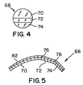
- FIG. 4 is a front view (not to scale) of a multi-focal lens.
- FIG. 5 is a side, sectional view (not to scale) of the lens of FIG. 4 .
- each numerical value should at least be construed in light of the number of reported significant digits and by applying ordinary rounding techniques.
- all ranges disclosed herein are to be understood to encompass the beginning and ending range values and any and all subranges subsumed therein.
- a stated range of “1 to 10” should be considered to include any and all subranges between (and inclusive of) the minimum value of 1 and the maximum value of 10; that is, all subranges beginning with a minimum value of 1 or more and ending with a maximum value of 10 or less, e.g., 1 to 3.3, 4.7 to 7.5, 5.5 to 10, and the like.
- the terms “formed over”, “deposited over”, or “applied over” mean formed, deposited, or applied on but not necessarily in contact with the surface.
- a coating “formed over” a substrate does not preclude the presence of one or more other coatings of the same or different composition located between the formed coating and the substrate.
- the terms “polymer” or “polymeric” refer to oligomers, homopolymers, copolymers, and terpolymers, e.g., polymers formed from two or more types of monomers or polymers.
- the terms “visible region” or “visible light” refer to electromagnetic radiation having a wavelength in the range of 380 nm to 800 nm.
- non-atomized coating sheet is meant that the coating material is not atomized, i.e., purposely mixed with air, as in a conventional spray coating method, to form a plurality of individual coating droplets. Rather, the coating material is dispersed under pressure, e.g., discharged from a nozzle under pressure, to form a continuous sheet or wall of non-atomized coating material.
- the optical articles produced in accordance with the invention meet commercially acceptable “cosmetic” standards for coated optical articles as known to those skilled in the art.
- the at least partially cured coated article may be substantially free of visually detectable cosmetic defects.
- cosmetic defects of a coated optical article include pits, spots, inclusions, cracks, non-uniformity of coating thickness, orange peel, ribbing, wrinkling, and crazing of the coating.
- the first coating device 10 includes a framework 12 , such as a metal framework, having at least one conveyor.
- the conveyor(s) may be configured to transport items in a substantially horizontal direction with respect to FIG. 1 .
- the coating device 10 includes a first conveyor 14 and a second conveyor 16 .
- the first and second conveyors 14 , 16 may be movably mounted on the framework 12 in any conventional manner, such as by rollers or wheels.
- the first and second conveyors 14 , 16 may move at the same or different speeds.
- the first coating device 10 further includes a holder 20 configured to support or hold an article 22 to be coated.
- the holder 20 may be a substantially rectangular metal holder configured to hold the article 22 on the holder 20 during coating.
- the holder 20 may comprise a depression or cut-out area that may have a surface complementary to the bottom surface of the article 22 such that the article 22 is securely held in the holder 20 .
- the holder 20 may be configured to hold the article 22 in a flat (or horizontal) position or to hold the article 22 at an angle (tilted or angled with respect to horizontal).
- a receiving platform 26 may be located at the end of the framework 12 to receive the holder 20 and coated article 22 after coating, as described in more detail below.
- the first coating device 10 further includes an applicator, such as a pressure-coating applicator.
- pressure-coating applicator or “pressure coater” is meant a device that propels coating material from the applicator under pressure.
- the coating applicator is a flow coater, such as a fan coater 30 , comprising a nozzle 32 in flow communication with a source 36 of coating material.
- the coating material and the source 36 may be under pressure or, alternatively, the source 36 may be in flow communication with a source 38 of pressurized fluid, such as pressurized air, to maintain the coating material under pressure.
- the fan coater nozzle 32 may be shaped and/or configured to provide a fan-shaped or wedge-shaped sheet or stream of non-atomized coating material 40 at a desired pressure.
- a flow coating device such as the fan coater 30 , provides a contiguous sheet of coating liquid that increases in size (e.g., width or diameter) from the point of discharge.
- the fan coater nozzle 32 discharges the solid stream of coating liquid in a wedge or fan shape.
- flow coaters do not atomize the discharged liquid but, rather, provide a solid sheet or stream of coating liquid.
- the fan coater nozzle 32 may be connected to a movement device 42 configured to move the fan coater nozzle 32 with respect to the conveyors 14 , 16 .
- the movement device 42 may raise or lower the nozzle 32 , move the nozzle 32 left or right with respect to a direction of movement 44 of the conveyors 14 , 16 , or tilt the nozzle 32 with respect to the direction of movement 44 .
- the coating device 52 includes a pressure-coating applicator, such as a fan coater 30 described above. Additionally, the coating device 52 includes a movement device 54 configured to move an article to be coated in a predetermined path, e.g., curved or non-linear path, through the fan of coating material 40 as described below.
- the movement device 54 comprises a motor 56 connected to a rotatable shaft 58 .
- a support such as an arm 60 , is connected to the shaft 58 .
- a holder 64 is carried on the arm 60 at or near the end opposite to the end connected to the shaft 58 .
- the holder 64 may be similar to the holder 20 described above and may be configured to hold one or more articles 22 to be coated.
- an article 22 to be coated may be placed in the holder 20 .
- the article 22 may be of any desired shape, e.g., flat, curved, or having both flat and curved portions, and may be of any desired dimension, e.g., length, width, or thickness.
- the article 22 may include any desired material having any desired characteristics.
- the article 22 may be transparent or translucent to visible light. By “transparent” is meant having visible light transmittance of greater than 0% to 100%. Alternatively, the article 22 may be translucent.
- translucent is meant allowing electromagnetic energy (e.g., visible light) to pass through but diffusing this energy such that objects on the side opposite the viewer are not clearly visible.
- the article 22 may be transparent or reflective of infrared or ultraviolet light.
- suitable materials include, but are not limited to, plastic substrates (such as acrylic polymers, such as polyacrylates; polyalkylmethacrylates, such as polymethylmethacrylates, polyethylmethacrylates, polypropylmethacrylates, and the like; polyurethanes; polycarbonates; polyalkylterephthalates, such as polyethyleneterephthalate (PET), polypropyleneterephthalates, polybutyleneterephthalates, and the like; polysiloxane-containing polymers; or copolymers of any monomers for preparing these, or any mixtures thereof).
- plastic substrates such as acrylic polymers, such as polyacrylates; polyalkylmethacrylates, such as polymethylmethacrylates, polyethylmeth
- the substrate may be a polymeric organic material, such as thermoset and thermoplastic polymeric organic materials, e.g., thermoplastic polycarbonate-type polymers and copolymers and homopolymers or copolymers of polyol(allyl carbonate) used as organic optical materials.
- thermoset and thermoplastic polymeric organic materials e.g., thermoplastic polycarbonate-type polymers and copolymers and homopolymers or copolymers of polyol(allyl carbonate) used as organic optical materials.
- Non-limiting examples of the aforementioned polymeric organic materials that can be used as substrates in conjunction with various non-limiting embodiments disclosed herein include polymeric materials, for example, homopolymers and copolymers, prepared from the monomers and mixtures of monomers disclosed in U.S. Pat. No. 6,733,887 at column 9, line 55 to column 17, line 7; in U.S. Pat. No. 5,658,501 at column 15, line 28 to column 16, line 17; and U.S. Pat. No. 6,352,747 at column 7, lines 15-53, the disclosures of which U.S. Patents are incorporated herein by reference in their entirety.
- the substrate is chosen from glass, ceramic, and polymeric organic materials and is an optical element, e.g., plano and vision correcting ophthalmic lenses, windows, clear polymeric films, automotive transparencies, e.g., windshields, aircraft transparencies, plastic sheeting, etc.
- the substrate is a polymeric organic material, such as optically clear polymerizates, e.g., materials suitable for optical applications, such as optical elements.
- optically clear polymerizates may have a refractive index that may vary widely. Examples of non-limiting embodiments include polymerizates of optical resins such as thermoplastic polycarbonate and optical resins sold by PPG Industries, Inc. as TRIVEX® monomer composition and under the CR- designation, e.g., CR-39® monomer composition.
- the substrate in one non-limiting embodiment, may be obtained as a preformed commercially available article to which the coating is applied, e.g., a glass and/or plastic lens, or the substrate may be produced in a process, e.g., a cast lens, immediately preceding the coating application.
- the preformed and/or cast lens may be subjected to surfacing and/or machining processes, e.g., front and/or rear surfacing and edging, to adjust the lens to the desired prescription and/or size of the intended frames before and/or after the coating application.
- the article 22 may be an optical lens, such as multi-focal or non-multi-focal glass or plastic lens, e.g., ophthalmic lens.
- a multi-focal lens 68 includes several regions or areas of different focal parameters.
- the multi-focal lens 68 shown in FIGS. 4 and 5 is configured as a conventional trifocal lens having a first focal region 70 , a second focal region 72 , and a third focal region 74 .
- the presence of the differing focal regions means that the lens 68 has a non-uniform or uneven surface, i.e., the outer surface is of non-uniform curvature.
- the invention is not limited to use with multi-focal lenses.
- the invention could also be practiced on conventional non-multi-focal lenses, i.e., lenses having a single focal prescription rather than a bifocal or trifocal lens.
- the invention is not limited to use with optical lenses. Examples of other optical articles that may be coated in the practice of the invention include motorcycle helmet visors, protective sports visors, goggles, binocular lenses, and telescope lenses, just to name a few.
- a lens 68 may be placed in the holder 20 .
- the fan coater 30 may be activated to provide a fan-shaped sheet of non-atomized coating material 40 at a desired set of application parameters, as described below.
- the conveyors 14 and 16 may be activated and set to desired speeds and the holder 20 may be placed on the first conveyor 14 .
- the first conveyor 14 transports the holder 20 in a predetermined path, e.g., along the movement direction 44 , into the sheet of coating material 40 to apply the coating material over the article 22 , onto the second conveyor 16 , and then onto the receiving platform 26 .
- the coated article 22 may be further processed, such as by heating or in other conventional ways, to cure or at least partially cure the applied coating material before or after the coated article 22 is removed from the holder 20 .
- the phrase “at least partially cure” refers to a coating in which some to all of the curable components of the coating are cured, e.g., reacted or polymerized.
- the coating material applied over the article 22 may be of any desired type.
- the coating material may be any coating material conventionally applied to such lenses, such as a polymeric coating.
- the coating material may be selected to provide a scratch-resistant or mar-resistant coating, an antireflective coating, a photochromic coating, an infrared or ultraviolet reflective coating, a polarization coating, an antistatic coating, or a temporary protective coating, just to name a few.
- scratch-resistant coatings are described in, but are not limited to, U.S. Patent Publication Nos.
- 20040096666 page 6, paragraph 68 to page 16, paragraph 148
- 20040156983 page 3, paragraph 37 to page 4, paragraph 56
- U.S. Pat. No. 6,680,125 column 2, line 65 to column 10, line 33
- Non-limiting examples of antireflective coatings are described in U.S. Pat. Nos. 6,632,535 (column 69, line 19 to column 74, line 50); 6,605,361 (column 2, line 51 to column 10, line 11); U.S. Patent Publication Nos. 20040234780 (page 2, paragraph 4 to page 3, paragraph 50 and page 4, paragraph 71 to page 6, paragraph 94); and 20040201822 (page 2, paragraph 25).
- Non-limiting examples of temporary protective coatings are described in U.S. Pat.
- the exact nature of the coating composition forming the coating material is not critical.
- the coating composition comprises a film-forming polymer.
- the coating composition used to produce the coated articles of the present invention comprises compositions adapted to provide thermoplastic or thermosetting coatings that are described in the Kirk - Othmer Encyclopedia of Chemical Technology , Fourth Edition, Volume 6, pages 669 to 760. Such coatings may be transparent, translucent or opaque.
- the coating is one that upon at least partial curing forms a polymeric coating chosen from polyurethanes, aminoplast resins, silanes, poly(meth)acrylates, e.g., polyacrylates and polymethacrylates, polyanhydrides, polyacrylamides, and epoxy resins.
- a polymeric coating chosen from polyurethanes, aminoplast resins, silanes, poly(meth)acrylates, e.g., polyacrylates and polymethacrylates, polyanhydrides, polyacrylamides, and epoxy resins.
- the nozzle 32 is positioned above the conveyors 14 and 16 such that the article 22 is at a distance in the range of 1 inch to 10 inches (2.5 cm to 25 cm), such as 2 inches to 7 inches (5 cm to 17.7 cm), such as 3 inches to 6 inches (7.6 cm to 15.2 cm), such as 5 inches (12.7 cm) from the nozzle 32 when the holder 20 passes through the fan of coating material 40 .
- the conveyors 14 and/or 16 may rotate at speeds such that the holder 20 is conveyed through the fan of coating material 40 at a speed in the range of 100 feet per minute to 1200 feet per minute (30.4 meters per minute to 360 meters per minute), such as 100 feet per minute to 800 feet per minute (30.4 meters per minute to 243.2 meters per minute), such as 200 feet per minute to 700 feet per minute (60.8 meters per minute to 212.8 meters per minute), such as 300 feet per minute to 600 feet per minute (91.2 meters per minute to 182.4 meters per minute), such as 500 feet per minute (152 meters per minute).
- the coating material 40 may be supplied to the nozzle 32 at a viscosity in the range of 20 centipoise to 400 centipoise (cp), such as 50 cp to 200 cp.
- the coating material 40 may be discharged at a nozzle pressure in the range of 2 psi to 30 psi (140 grams per square centimeter to 2109 grams per square centimeter).
- the fan of coating material 40 may have a fan width in the range of 4 inches to 10 inches (10.2 cm to 25.4 cm), such as 5 inches to 7 inches (12.7 cm to 17.8 cm), such as 6.5 inches (16.5 cm) at the position where the holder 20 passes through the fan of coating material 40 .
- fan width is meant the lateral width of the fan-shaped sheet of coating material 40 .
- the holder 20 may be positioned on the conveyors 14 and 16 such that the holder 20 passes through the center of the fan of coating materials 40 .
- the holder 20 may be offset on the conveyors 14 and 16 such that the holder 20 passes through the fan of coating material 40 at a fan offset.
- fan offset is meant the lateral distance of the holder 20 from the center of the fan of coating material 40 .
- the fan offset may be in the range of 0.5 inch to 4 inches (1.3 cm to 10 cm), such as 1 inch to 2 inches (2.54 cm to 5.1 cm), such as 1.5 inches (3.8 cm).
- the nozzle 32 may be positioned at an angle with respect to the movement direction 44 such that the fan of coating material 40 is directed at the holder 20 at a coating angle 90 in the range of ⁇ 45° with respect to a vertical axis V perpendicular to the direction of travel 44 (i.e., 90° from the direction of travel 44 ), such as ⁇ 30°, such as ⁇ 25°, such as ⁇ 20°, such as ⁇ 15°, such as ⁇ 10°, such as ⁇ 5°, such as ⁇ 0°.
- ⁇ 25° is meant that the nozzle 32 would be tilted to the left in FIG. 1 by 25° from a vertical axis V.
- +25° would mean that the nozzle 32 would be tilted to the right in FIG. 1 by 25° from the vertical axis V.
- the thickness of the aforedescribed coating may vary widely.
- the at least partially cured coating may have a thickness of from 1 to 10,000 microns.
- the coating thickness may be from 5 to 1,000 microns.
- the coating thickness may be from 10 to 400 microns, e.g., 30 microns.
- An article 22 may be placed in the holder 64 .
- the fan coater 30 may be activated to provide a fan-shaped sheet of non-atomized coating material 40 .
- the motor 56 may be activated to turn the arm 60 to cause the holder 64 to pass through the fan of coating material 40 in a predetermined path, such as a curved path, as shown particularly in FIG. 2 .
- the holder 64 may pass through the sheet of coating material 40 once or several times while rotating in one direction or, the arm 60 may pass through the sheet of coating material 40 in one direction and then the motor 56 may be reversed to cause the holder 64 to pass through the coating sheet in the opposite direction.
- the coating deposition parameters, coating thickness, etc. may be as described above for the coating device 10 .
- the article 22 may be positioned horizontally in the holder 64 .
- the holder 64 and/or the article 22 may be tilted or angled such that the article 22 passes through the sheet of coating material 40 at an angle from horizontal, such as an angle from 0° to 90° with respect to horizontal.
Landscapes
- Engineering & Computer Science (AREA)
- Health & Medical Sciences (AREA)
- Manufacturing & Machinery (AREA)
- Ophthalmology & Optometry (AREA)
- Mechanical Engineering (AREA)
- Eyeglasses (AREA)
- Application Of Or Painting With Fluid Materials (AREA)
- Surface Treatment Of Optical Elements (AREA)
Priority Applications (9)
| Application Number | Priority Date | Filing Date | Title |
|---|---|---|---|
| US11/105,827 US7757629B2 (en) | 2005-04-14 | 2005-04-14 | Method and apparatus for coating an optical article |
| BRPI0612335-0A BRPI0612335A2 (pt) | 2005-04-14 | 2006-03-08 | método para revestir um artigo óptico, artigo óptico e aparelho para revestir um artigo óptico |
| PCT/US2006/008355 WO2006112965A1 (en) | 2005-04-14 | 2006-03-08 | Method and apparatus for coating articles |
| CN2006800119828A CN101160180B (zh) | 2005-04-14 | 2006-03-08 | 用于涂覆制品的方法和设备 |
| AU2006237566A AU2006237566B2 (en) | 2005-04-14 | 2006-03-08 | Method and apparatus for coating articles |
| JP2008505311A JP4845959B2 (ja) | 2005-04-14 | 2006-03-08 | 物品をコーティングする方法および装置 |
| EP06737521A EP1868735B1 (en) | 2005-04-14 | 2006-03-08 | Method and apparatus for coating articles |
| KR1020077023320A KR100912993B1 (ko) | 2005-04-14 | 2007-10-11 | 제품을 코팅하는 방법 및 장치 |
| JP2010220069A JP2011022607A (ja) | 2005-04-14 | 2010-09-29 | 物品をコーティングする方法および装置 |
Applications Claiming Priority (1)
| Application Number | Priority Date | Filing Date | Title |
|---|---|---|---|
| US11/105,827 US7757629B2 (en) | 2005-04-14 | 2005-04-14 | Method and apparatus for coating an optical article |
Publications (2)
| Publication Number | Publication Date |
|---|---|
| US20060231022A1 US20060231022A1 (en) | 2006-10-19 |
| US7757629B2 true US7757629B2 (en) | 2010-07-20 |
Family
ID=36649685
Family Applications (1)
| Application Number | Title | Priority Date | Filing Date |
|---|---|---|---|
| US11/105,827 Active 2028-03-19 US7757629B2 (en) | 2005-04-14 | 2005-04-14 | Method and apparatus for coating an optical article |
Country Status (8)
| Country | Link |
|---|---|
| US (1) | US7757629B2 (pt) |
| EP (1) | EP1868735B1 (pt) |
| JP (2) | JP4845959B2 (pt) |
| KR (1) | KR100912993B1 (pt) |
| CN (1) | CN101160180B (pt) |
| AU (1) | AU2006237566B2 (pt) |
| BR (1) | BRPI0612335A2 (pt) |
| WO (1) | WO2006112965A1 (pt) |
Cited By (7)
| Publication number | Priority date | Publication date | Assignee | Title |
|---|---|---|---|---|
| US20100062169A1 (en) * | 2008-09-08 | 2010-03-11 | JN Machinery | Coating high temperature parts with polymer |
| US8820923B2 (en) | 2011-08-05 | 2014-09-02 | Nitto Denko Corporation | Optical element for correcting color blindness |
| US8931930B2 (en) | 2013-01-29 | 2015-01-13 | Nitto Denko Corporation | Optical element for correcting color blindness |
| WO2016142496A1 (en) | 2015-03-10 | 2016-09-15 | Transitions Optical, Ltd. | Optical element having a coating for enhanced visibility of a mark and method for making the optical element |
| US11076627B2 (en) | 2017-12-22 | 2021-08-03 | Marel Further Processing B.V. | Coating of food products with a particulate coating material |
| US11771552B2 (en) | 2013-03-13 | 2023-10-03 | Acufocus, Inc. | In situ adjustable optical mask |
| US12097521B2 (en) | 2016-07-15 | 2024-09-24 | Transitions Optical, Ltd. | Apparatus and method for precision coating of ophthalmic lenses with photochromic coatings |
Families Citing this family (12)
| Publication number | Priority date | Publication date | Assignee | Title |
|---|---|---|---|---|
| US20070264426A1 (en) * | 2006-05-12 | 2007-11-15 | Essilor International Compagnie Generale D'optique | Optical lens coating apparatus and method |
| FR2910642B1 (fr) * | 2006-12-26 | 2009-03-06 | Essilor Int | Composant optique transparent a deux ensembles de cellules |
| JP2010191295A (ja) * | 2009-02-19 | 2010-09-02 | Hoya Corp | バイフォーカルレンズのコーティング方法 |
| US10814351B2 (en) * | 2013-08-12 | 2020-10-27 | The Boeing Company | High-viscosity sealant application system |
| KR20160006401A (ko) | 2014-07-09 | 2016-01-19 | 주식회사 케이오씨솔루션 | 기능성 코팅층이 형성된 광학렌즈의 제조방법 |
| KR20160012787A (ko) | 2014-07-25 | 2016-02-03 | 주식회사 케이오씨솔루션 | 광학렌즈에 기능성 코팅층을 형성하는 방법 및 기능성 코팅층이 형성된 광학렌즈 |
| KR101712071B1 (ko) | 2015-01-19 | 2017-03-03 | 주식회사 케이오씨솔루션 | 광변색층이 형성된 광변색렌즈 및 그 제조방법 |
| KR102634160B1 (ko) | 2017-11-30 | 2024-02-06 | 악살타 코팅 시스템즈 게엠베하 | 고 전달 효율 어플리케이터를 활용하는 코팅 조성물의 적용을 위한 시스템, 코팅 층 및 상응하는 방법 |
| US12539525B2 (en) | 2017-11-30 | 2026-02-03 | Axalta Coating Systems Ip Co., Llc | Coating compositions for application utilizing a high transfer efficiency applicator and methods and systems thereof |
| DE102018008957A1 (de) * | 2018-11-14 | 2020-05-14 | Shape Engineering GmbH | Verfahren zur Beschichtung von Brillengläsern |
| CN109702844B (zh) * | 2018-12-14 | 2021-11-12 | 林燕 | 一种木质制品自动包裹树脂的加工设备 |
| US12122932B2 (en) | 2020-05-29 | 2024-10-22 | Axalta Coating Systems Ip Co., Llc | Coating compositions for application utilizing a high transfer efficiency applicator and methods and systems thereof |
Citations (14)
| Publication number | Priority date | Publication date | Assignee | Title |
|---|---|---|---|---|
| US3132966A (en) * | 1960-03-24 | 1964-05-12 | Ti Group Services Ltd | Process of coating a surface with an irradiated polymerizable material |
| US3242003A (en) * | 1962-10-31 | 1966-03-22 | Swift & Co | Method and apparatus for interrupting liquid coating |
| US3341354A (en) * | 1964-03-11 | 1967-09-12 | Continental Oil Co | Curtain coating method and apparatus for applying a non-uniform liquid coating material to sheet stock |
| US3383054A (en) * | 1967-07-31 | 1968-05-14 | Crompton & Knowles Corp | Coating nozzle |
| US3500610A (en) * | 1962-03-07 | 1970-03-17 | Eastman Kodak Co | Apparatus for coating an article with a liquid substantially free from discrete immiscible matter |
| US3830608A (en) * | 1971-12-30 | 1974-08-20 | Mallet & Co Inc | Automatic machine for greasing bakery pans and depositing batter therein |
| US3876465A (en) * | 1973-03-12 | 1975-04-08 | Zenith Radio Corp | Method and apparatus for coating skirtless cathode ray tube panels |
| US4961965A (en) | 1989-06-29 | 1990-10-09 | Minnesota Mining And Manufacturing Company | Method and apparatus for automated dispensing of liquid materials onto a workpiece |
| US5114740A (en) | 1989-01-13 | 1992-05-19 | Ford Motor Company | Method and apparatus for providing antistatic protection to plastic lenses |
| US5246499A (en) | 1991-05-20 | 1993-09-21 | Bmc Industries, Inc. | Apparatus for applying scratch-resistant coatings to plastic ophthalmic lenses |
| US5900273A (en) | 1996-01-19 | 1999-05-04 | Micron Technology, Inc. | Method for coating a substrate covered with a plurality of spacer members |
| US6033718A (en) | 1997-06-03 | 2000-03-07 | Indo Internacional, S.A. | Apparatus and process for applying a protective coating to a lens disc |
| US6379776B1 (en) | 1996-12-18 | 2002-04-30 | Nippon Sheet Glass Co., Ltd. | Nonfogging and stainproof glass articles |
| US20050244571A1 (en) | 2002-05-21 | 2005-11-03 | Interfloat Corporation | Method and device for the production of an antireflective coating, antireflective coating, and antireflective-coated substrate |
Family Cites Families (8)
| Publication number | Priority date | Publication date | Assignee | Title |
|---|---|---|---|---|
| JPS5653775A (en) * | 1979-10-05 | 1981-05-13 | Olympus Optical Co Ltd | Painting device for optical fiber |
| JPH10513112A (ja) | 1995-02-02 | 1998-12-15 | ミネソタ・マイニング・アンド・マニュファクチャリング・カンパニー | 薄膜液状コーティングを適用するための方法および装置 |
| JPH09230108A (ja) * | 1995-12-22 | 1997-09-05 | Toto Ltd | 防曇性プラスチックレンズ、及びその防曇方法 |
| US6547390B1 (en) * | 2000-09-11 | 2003-04-15 | Exxene Corporation | Top stabilized photochromic lens system |
| EP1506140A1 (de) * | 2002-05-21 | 2005-02-16 | Interfloat Corporation | Verfahren und verwendung einer vorrichtung zur beschichtung von plattenförmigen substraten |
| JP4273709B2 (ja) * | 2002-06-19 | 2009-06-03 | セイコーエプソン株式会社 | 光学部材の製造方法 |
| JP3979353B2 (ja) * | 2002-08-02 | 2007-09-19 | セイコーエプソン株式会社 | 塗布方法 |
| JP4211474B2 (ja) * | 2003-04-28 | 2009-01-21 | 凸版印刷株式会社 | 成型シート及びその製造方法 |
-
2005
- 2005-04-14 US US11/105,827 patent/US7757629B2/en active Active
-
2006
- 2006-03-08 EP EP06737521A patent/EP1868735B1/en not_active Expired - Fee Related
- 2006-03-08 JP JP2008505311A patent/JP4845959B2/ja not_active Expired - Fee Related
- 2006-03-08 WO PCT/US2006/008355 patent/WO2006112965A1/en not_active Ceased
- 2006-03-08 AU AU2006237566A patent/AU2006237566B2/en not_active Ceased
- 2006-03-08 BR BRPI0612335-0A patent/BRPI0612335A2/pt not_active IP Right Cessation
- 2006-03-08 CN CN2006800119828A patent/CN101160180B/zh not_active Expired - Lifetime
-
2007
- 2007-10-11 KR KR1020077023320A patent/KR100912993B1/ko not_active Expired - Fee Related
-
2010
- 2010-09-29 JP JP2010220069A patent/JP2011022607A/ja not_active Withdrawn
Patent Citations (14)
| Publication number | Priority date | Publication date | Assignee | Title |
|---|---|---|---|---|
| US3132966A (en) * | 1960-03-24 | 1964-05-12 | Ti Group Services Ltd | Process of coating a surface with an irradiated polymerizable material |
| US3500610A (en) * | 1962-03-07 | 1970-03-17 | Eastman Kodak Co | Apparatus for coating an article with a liquid substantially free from discrete immiscible matter |
| US3242003A (en) * | 1962-10-31 | 1966-03-22 | Swift & Co | Method and apparatus for interrupting liquid coating |
| US3341354A (en) * | 1964-03-11 | 1967-09-12 | Continental Oil Co | Curtain coating method and apparatus for applying a non-uniform liquid coating material to sheet stock |
| US3383054A (en) * | 1967-07-31 | 1968-05-14 | Crompton & Knowles Corp | Coating nozzle |
| US3830608A (en) * | 1971-12-30 | 1974-08-20 | Mallet & Co Inc | Automatic machine for greasing bakery pans and depositing batter therein |
| US3876465A (en) * | 1973-03-12 | 1975-04-08 | Zenith Radio Corp | Method and apparatus for coating skirtless cathode ray tube panels |
| US5114740A (en) | 1989-01-13 | 1992-05-19 | Ford Motor Company | Method and apparatus for providing antistatic protection to plastic lenses |
| US4961965A (en) | 1989-06-29 | 1990-10-09 | Minnesota Mining And Manufacturing Company | Method and apparatus for automated dispensing of liquid materials onto a workpiece |
| US5246499A (en) | 1991-05-20 | 1993-09-21 | Bmc Industries, Inc. | Apparatus for applying scratch-resistant coatings to plastic ophthalmic lenses |
| US5900273A (en) | 1996-01-19 | 1999-05-04 | Micron Technology, Inc. | Method for coating a substrate covered with a plurality of spacer members |
| US6379776B1 (en) | 1996-12-18 | 2002-04-30 | Nippon Sheet Glass Co., Ltd. | Nonfogging and stainproof glass articles |
| US6033718A (en) | 1997-06-03 | 2000-03-07 | Indo Internacional, S.A. | Apparatus and process for applying a protective coating to a lens disc |
| US20050244571A1 (en) | 2002-05-21 | 2005-11-03 | Interfloat Corporation | Method and device for the production of an antireflective coating, antireflective coating, and antireflective-coated substrate |
Cited By (14)
| Publication number | Priority date | Publication date | Assignee | Title |
|---|---|---|---|---|
| US20100062169A1 (en) * | 2008-09-08 | 2010-03-11 | JN Machinery | Coating high temperature parts with polymer |
| US10119070B2 (en) | 2011-08-05 | 2018-11-06 | Nitto Denko Corporation | Optical element for correcting color blindness |
| US8845095B2 (en) | 2011-08-05 | 2014-09-30 | Nitto Denko Corporation | Optical element for correcting color blindness |
| US8939576B2 (en) | 2011-08-05 | 2015-01-27 | Nitto Denko Corporation | Optical element for correcting color blindness |
| US8963104B2 (en) | 2011-08-05 | 2015-02-24 | Nitto Denko Corporation | Optical element for correcting color blindness |
| US9022562B2 (en) | 2011-08-05 | 2015-05-05 | Nitto Denko Corporation | Optical element for correcting color blindness |
| US9574067B2 (en) | 2011-08-05 | 2017-02-21 | Nitto Denko Corporation | Optical element for correcting color blindness |
| US8820923B2 (en) | 2011-08-05 | 2014-09-02 | Nitto Denko Corporation | Optical element for correcting color blindness |
| US8931930B2 (en) | 2013-01-29 | 2015-01-13 | Nitto Denko Corporation | Optical element for correcting color blindness |
| US11771552B2 (en) | 2013-03-13 | 2023-10-03 | Acufocus, Inc. | In situ adjustable optical mask |
| WO2016142496A1 (en) | 2015-03-10 | 2016-09-15 | Transitions Optical, Ltd. | Optical element having a coating for enhanced visibility of a mark and method for making the optical element |
| US10371866B2 (en) | 2015-03-10 | 2019-08-06 | Transitions Optical, Ltd. | Optical element having a coating for enhanced visibility of a mark and method for making the optical element |
| US12097521B2 (en) | 2016-07-15 | 2024-09-24 | Transitions Optical, Ltd. | Apparatus and method for precision coating of ophthalmic lenses with photochromic coatings |
| US11076627B2 (en) | 2017-12-22 | 2021-08-03 | Marel Further Processing B.V. | Coating of food products with a particulate coating material |
Also Published As
| Publication number | Publication date |
|---|---|
| KR100912993B1 (ko) | 2009-08-20 |
| JP4845959B2 (ja) | 2011-12-28 |
| CN101160180B (zh) | 2012-11-07 |
| AU2006237566B2 (en) | 2010-03-18 |
| EP1868735B1 (en) | 2011-05-11 |
| JP2011022607A (ja) | 2011-02-03 |
| KR20070112259A (ko) | 2007-11-22 |
| US20060231022A1 (en) | 2006-10-19 |
| JP2008535035A (ja) | 2008-08-28 |
| BRPI0612335A2 (pt) | 2010-11-03 |
| CN101160180A (zh) | 2008-04-09 |
| WO2006112965A1 (en) | 2006-10-26 |
| EP1868735A1 (en) | 2007-12-26 |
| AU2006237566A1 (en) | 2006-10-26 |
Similar Documents
| Publication | Publication Date | Title |
|---|---|---|
| KR100912993B1 (ko) | 제품을 코팅하는 방법 및 장치 | |
| US10571611B2 (en) | Spin coater for applying multiple coatings to an optical substrate | |
| US12103325B2 (en) | Coating system for coating an optical substrate, method thereof and coated optical substrate | |
| US20100086700A1 (en) | Method of producing coated lenses | |
| EP2851713B1 (en) | Optical article with gradient photochromism | |
| US20020104479A1 (en) | Method and apparatus for coating plate | |
| US20150321948A1 (en) | Method and system for coating glass edges | |
| US20020127347A1 (en) | Method and apparatus for producing coated plate | |
| US20100203240A1 (en) | Method for spin coating a surface of an optical article | |
| US20050213923A1 (en) | Method and apparatus for applying materials to an optical substrate |
Legal Events
| Date | Code | Title | Description |
|---|---|---|---|
| AS | Assignment |
Owner name: TRANSITIONS OPTICAL, INC., FLORIDA Free format text: ASSIGNMENT OF ASSIGNORS INTEREST;ASSIGNORS:LYDON, MICHAEL T.;BLACKBURN, WILLIAM P.;MALDONADO, ERNESTO;AND OTHERS;SIGNING DATES FROM 20050524 TO 20050531;REEL/FRAME:016718/0249 Owner name: TRANSITIONS OPTICAL, INC., FLORIDA Free format text: ASSIGNMENT OF ASSIGNORS INTEREST;ASSIGNORS:LYDON, MICHAEL T.;BLACKBURN, WILLIAM P.;MALDONADO, ERNESTO;AND OTHERS;REEL/FRAME:016718/0249;SIGNING DATES FROM 20050524 TO 20050531 |
|
| STCF | Information on status: patent grant |
Free format text: PATENTED CASE |
|
| FPAY | Fee payment |
Year of fee payment: 4 |
|
| AS | Assignment |
Owner name: TRANSITIONS OPTICAL LIMITED, IRELAND Free format text: LICENSE;ASSIGNOR:TRANSITIONS OPTICAL, INC.;REEL/FRAME:038378/0629 Effective date: 20151101 |
|
| MAFP | Maintenance fee payment |
Free format text: PAYMENT OF MAINTENANCE FEE, 8TH YEAR, LARGE ENTITY (ORIGINAL EVENT CODE: M1552) Year of fee payment: 8 |
|
| MAFP | Maintenance fee payment |
Free format text: PAYMENT OF MAINTENANCE FEE, 12TH YEAR, LARGE ENTITY (ORIGINAL EVENT CODE: M1553); ENTITY STATUS OF PATENT OWNER: LARGE ENTITY Year of fee payment: 12 |