US8042684B2 - Receiving element for a dental implant - Google Patents
Receiving element for a dental implant Download PDFInfo
- Publication number
- US8042684B2 US8042684B2 US12/602,687 US60268708A US8042684B2 US 8042684 B2 US8042684 B2 US 8042684B2 US 60268708 A US60268708 A US 60268708A US 8042684 B2 US8042684 B2 US 8042684B2
- Authority
- US
- United States
- Prior art keywords
- receiving element
- plate
- dental implant
- center axis
- implant according
- Prior art date
- Legal status (The legal status is an assumption and is not a legal conclusion. Google has not performed a legal analysis and makes no representation as to the accuracy of the status listed.)
- Active
Links
- 239000004053 dental implant Substances 0.000 title claims abstract description 52
- 230000003014 reinforcing effect Effects 0.000 claims description 5
- 239000000463 material Substances 0.000 claims description 2
- 230000004308 accommodation Effects 0.000 claims 1
- 239000007943 implant Substances 0.000 description 29
- 239000003708 ampul Substances 0.000 description 9
- 238000003780 insertion Methods 0.000 description 7
- 230000037431 insertion Effects 0.000 description 7
- 238000000034 method Methods 0.000 description 4
- 238000004519 manufacturing process Methods 0.000 description 3
- 238000010276 construction Methods 0.000 description 2
- 230000000694 effects Effects 0.000 description 2
- 230000002787 reinforcement Effects 0.000 description 2
- 238000003860 storage Methods 0.000 description 2
- 238000011477 surgical intervention Methods 0.000 description 2
- 230000015572 biosynthetic process Effects 0.000 description 1
- 210000000988 bone and bone Anatomy 0.000 description 1
- 239000002775 capsule Substances 0.000 description 1
- 238000005266 casting Methods 0.000 description 1
- 238000006243 chemical reaction Methods 0.000 description 1
- 230000006835 compression Effects 0.000 description 1
- 238000007906 compression Methods 0.000 description 1
- 239000004035 construction material Substances 0.000 description 1
- 230000001419 dependent effect Effects 0.000 description 1
- 238000005516 engineering process Methods 0.000 description 1
- 238000001746 injection moulding Methods 0.000 description 1
- 230000000670 limiting effect Effects 0.000 description 1
- 238000003754 machining Methods 0.000 description 1
- 238000011017 operating method Methods 0.000 description 1
- 238000005096 rolling process Methods 0.000 description 1
- 238000001356 surgical procedure Methods 0.000 description 1
- 230000003313 weakening effect Effects 0.000 description 1
Images


Classifications
-
- A—HUMAN NECESSITIES
- A61—MEDICAL OR VETERINARY SCIENCE; HYGIENE
- A61C—DENTISTRY; APPARATUS OR METHODS FOR ORAL OR DENTAL HYGIENE
- A61C8/00—Means to be fixed to the jaw-bone for consolidating natural teeth or for fixing dental prostheses thereon; Dental implants; Implanting tools
- A61C8/0087—Means for sterile storage or manipulation of dental implants
-
- A—HUMAN NECESSITIES
- A61—MEDICAL OR VETERINARY SCIENCE; HYGIENE
- A61C—DENTISTRY; APPARATUS OR METHODS FOR ORAL OR DENTAL HYGIENE
- A61C19/00—Dental auxiliary appliances
- A61C19/02—Protective casings, e.g. boxes for instruments; Bags
-
- A—HUMAN NECESSITIES
- A61—MEDICAL OR VETERINARY SCIENCE; HYGIENE
- A61C—DENTISTRY; APPARATUS OR METHODS FOR ORAL OR DENTAL HYGIENE
- A61C8/00—Means to be fixed to the jaw-bone for consolidating natural teeth or for fixing dental prostheses thereon; Dental implants; Implanting tools
Definitions
- the present invention relates to a receiving element for an implant, in particular for screw- or cylinder-shaped implants.
- Such implants are already known e.g. from dental technology and are substantially similar to a screw, the apical area of the screw being inserted in a bone and the coronal area being suitable to receive a dental prosthesis.
- different embodiments of holding elements fastened to the implant which, on the one hand, fix the implant into place and, on the other hand, allow sterile removal from the receiving element.
- they also ensure that from manufacturing until surgical intervention, an implant does not come in contact with non-sterile means, such as hands.
- the relevant area of application for the invention is where the implants, e.g. for reasons of necessary sterile handling, may at least not directly be touched with one's hands, and where secure grasping of the implants is required.
- receiving elements The function of such receiving elements is to transport the implant safely and provide a sterile environment for storage.
- the implant is taken from the receiving element which generally has a holding element fastened to the implant (in the following, the combination of implant and holding element attached to it will be called implant assembly for simplification), e.g. by means of a tool applied to the implant, and the implant is subsequently placed on the prepared implant site of the patient and the holding element is removed.
- implant assembly for simplification
- a cylindrical ampule to be inserted in an outer capsule which ampule is suitable for receiving an implant.
- the ampule has a face region provided with an recess which is laterally open. This recess is used to insert an implant assembly consisting of the implant and a holding element additionally connected to the implant.
- the implant assembly is fixed into place in a throat of the ampule by being pressed through an opening.
- substantial pressure must be applied when the implant is pressed in; with a rigid structure of an ampule and a receiving element, the consequence is that the construction material is subjected to substantial stress, since the forces that occur spread both along the expansion groove and along the cylinder surface.
- the face side of the ampule has a relatively small cross-section, and the entire holding force between an implant and the interior of the throat is limited to this narrow area, the holding force or withdrawal force, respectively, being consequently increased by the pressure or compression, respectively, when the implant is removed from the holder. This increases the grip on the implant, making the removal process difficult to control.
- the cylindrical ampule can move about its axis within a certain range, which makes it difficult to grip.
- the object of the present invention is to provide a receiving element for a dental implant which fixes a dental implant assembly in place more secure and which can better convert and carry off the forces occurring when the dental implant assembly is placed on the structure of the receiving element. Furthermore, simpler and safer handling should be provided and economical manufacturing with existing techniques should be possible.
- the object of the present invention is to provide a receiving element for a dental implant having improved stability and conversion of forces and which avoids the drawbacks mentioned above.
- another object of the present invention is to provide a receiving element for a dental implant which is better protected against slipping on a surface.
- Another object of the present invention is that the receiving element can be handled more easily and more safely.
- Another object of the present invention is that the receiving element can be manufactured easily and inexpensively with well-known methods.
- the constructive characteristics of a substantially cylindrical receiving element according to the present invention consist in that the head area holding the receiving element is nearly uncoupled from the body so that forces occurring during removal of the dental implant from the holder through the aperture provided for this purpose are effectively diverted and/or completely eliminated.
- the substantially square body portion is advantageously provided with an open side for easy insertion of the dental implant.
- the head area has a first surface suitable for clamping connection with a dental implant and a second surface which prevents the dental implant from touching the interior wall of the body part.
- one side of the receiving element is provided with a plane surface ensuring stable positioning on a surface such as the operating table.
- the receiving element has a plurality of reinforcing ribs in its body area which, on the one hand, reinforce the outer wall and, on the other hand, ensure a better grip.
- FIG. 1 shows a side view of a receiving element for a dental implant according to an embodiment of the invention
- FIG. 2 shows a front view of a receiving element for a dental implant according to FIG. 1 ;
- FIG. 3 shows a longitudinal section of a receiving element for a dental implant according to FIG. 1 , taken along line A-A in the direction of the arrow;
- FIG. 4 shows a longitudinal section of a receiving element for a dental implant according to FIG. 1 , taken along line B-B in the direction of the arrow;
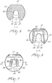
- FIG. 5 shows a sectional view of a receiving element for a dental implant according to FIG. 1 , taken along line F-F in the direction of the arrow;
- FIG. 6 shows a sectional view of a receiving element for a dental implant according to FIG. 1 , taken along line D-D in the direction of the arrow;
- FIG. 7 shows a top view of a receiving element for a dental implant according to FIG. 1 .
- a currently preferred embodiment of the present invention of a receiving element for a dental implant is described, which element consists of a substantially cylindrical bottom area, a body area enclosing the dental implant and a flexible head area formed by two plates, the head area being provided with a clamping device for receiving a dental implant, which device is suitable for releasably clamping and fixing a dental implant into place.
- FIG. 1 shows a receiving element 1 for a dental implant, the receiving element 1 basically having three portions.
- a first portion forming the head area consists of an approximately C-shaped, plane front face 2 comprising a first plate 3 which is suitable for fixing a dental implant (not shown) into place, as is described further in the foregoing.
- the first plate 3 is adjacent to an open area 5 surrounded by a first shoulder 4 bordering on the first plate 3 and a second shoulder 4 ′ below it which borders on a second plate 6 .
- the open area 5 which is preferably jaw-shaped preferably extends from its open side at a respective end of the plates 3 , 6 to a theoretical center axis Z of the receiving element 1 , the opening width in the area of the center axis Z being advantageously smaller than on the outer side.
- the jaw-like area 5 achieves a mechanical uncoupling of the plates 3 , 6 and of the first plate 3 from the body 7 , respectively.
- a chamfer 17 from an outer edge of the plane front face 2 to a plane head area 16 is provided, the plane head area 16 bordering on a plane head edge 15 which borders both on the head area 16 and on a body 7 of the receiving element 1 .
- Part of the second plate 6 which borders on the jaw-like open area 5 and on the second shoulder 4 ′, respectively, is substantially plane.
- the part of the second plate 6 which is below the jaw-like area 5 then borders on a second portion formed by the body 7 and provided with a plurality of symmetrically arranged reinforcing ribs 8 .
- these reinforcing ribs 8 have a longitudinal shape.
- a base surface 9 borders on the edge of the body 7 opposite to the second plate 6 , which base surface is substantially symmetrically round and on which the body 7 is arranged perpendicularly.
- the third portion comprises a perimetric surrounding edge 10 embedded between the base surface 9 and a bottom part 11 , with the bottom part 11 transitioning on one side into the standing area 12 which is suitable for the placement on a surface.
- a bottom portion 13 formed between the bottom edge 14 and the standing area 12 is preferably plane.
- the bottom edge 14 which is also plane borders on the bottom portion 13 . Due to the plane embodiment of the head edge 15 and of the bottom edge 14 , it is possible to position the receiving element 1 stably on a surface and to both prevent it from rolling away and to grip it easily.
- FIG. 2 shows further features of the receiving element 1 , a first through hole 23 and a second through hole 24 being arranged in the center of the first plate 3 .
- the second through hole 24 can preferably have a smaller diameter than the first through hole 23 , although in the presently preferred embodiment the difference in diameter is not indispensable.
- the first through hole 23 and the second through hole 24 are, in one place, connected to each other by an open groove 39 as is also shown in FIG. 7 .
- the first through hole 23 borders on an opening 40 , see FIG. 7 , of the first plate 3 .
- a first elongated hole 18 and a second elongated hole 19 are provided in the body 7 as can be seen in FIG. 2 .
- FIG. 3 and FIG. 4 show additional features of the receiving element 1 , a portion of the first plate 3 being provided with a chamfered leg 22 which extends from the outer edge approximately up to the area of a theoretical center axis Z of the receiving element 1 , the chamfered leg 22 allowing an easy insertion of a dental implant.
- the first plate 3 can be elastically deformed with respect to the second plate 6 in a direction perpendicular to the center axis Z of the receiving element 1 until the dental implant is locked into place in the first through hole 23 and held there clampingly, a first gap 36 and a second gap 37 of the jaw-like portion 5 mechanically uncoupling the first plate 3 from the body 7 and from the second plate 6 , respectively, as mentioned above.
- the chamfer 17 on the opposite side advantageously has a resilient effect.
- a first reinforcement 20 and a second reinforcement 21 are used to strengthen the construction against the tensions produced when the dental implant is pressed in.
- a first notch 34 and a second notch 35 which can have a conical shape and which are arranged symmetrically in the first plate 3 and adjacent to the first through hole 23 and the second through hole 24 are suitable for distributing the forces when the dental implant is pressed in through the opening 40 of the first plate 3 , and the first plate 3 can be expanded elastically in a direction perpendicular to the center axis Z.
- the conical shape of the notches is preferred especially for machining reasons if the receiving element is manufactured by injection molding.
- the second through hole 24 has a smaller diameter than the first through hole 23 and is connected to it by the groove 39 so that the through hole 24 is used as an expansion through hole and can be enlarged when a dental implant is pressed in.
- the elastic deformability of the first plate 3 advantageously results both in a clamping and in a snap-in connection which securely fixes the dental implant in the first through hole 23 .
- FIG. 5 and FIG. 6 show the head area of the receiving element 1 , FIG. 5 showing an area 41 which has, in the portion of the opening 40 , see FIG. 7 , a first chamfer 26 and a second chamfer 27 used for easy insertion of the dental implant.
- the angle between the first and the second chamfer is preferably within a range of 80 to 120 degrees.
- the area 41 which is enclosed over the entire cross-section up to the chamfers 26 , 27 is rigid so as to form the U-shaped portion 32 shown in FIG. 6 .
- the inner surface of the U-shaped portion 32 forms a stopping portion 33 in which an inserted dental implant is kept in a stable position so that contact with the interior walls of the body 7 , e. g. during transport, is excluded.
- the base surface 9 from FIG. 1 has an annular portion 25 having approximately the width of the U-shaped portion 32 and, in its center, the base surface has a third through hole 42 with a larger diameter than the first and the second through hole 23 , 24 .
- FIG. 7 shows that the first through hole 23 is aligned with the third through hole 42 .
- the first notch 34 and the second notch 35 extend substantially parallel thereto, slightly curving in the direction of the center of the second through hole 24 near the first 23 and the second 24 through hole.
- the receiving element 1 can be manufactured with conventional processes, e. g. casting, and is preferably made of an elastic plastic material.
Landscapes
- Health & Medical Sciences (AREA)
- Oral & Maxillofacial Surgery (AREA)
- Dentistry (AREA)
- Epidemiology (AREA)
- Life Sciences & Earth Sciences (AREA)
- Animal Behavior & Ethology (AREA)
- General Health & Medical Sciences (AREA)
- Public Health (AREA)
- Veterinary Medicine (AREA)
- Orthopedic Medicine & Surgery (AREA)
- Dental Prosthetics (AREA)
Applications Claiming Priority (4)
| Application Number | Priority Date | Filing Date | Title |
|---|---|---|---|
| DE102007026504 | 2007-06-05 | ||
| DE102007026504A DE102007026504A1 (de) | 2007-06-05 | 2007-06-05 | Aufnahmeelement für ein Implantat |
| DE102007026504.4 | 2007-06-05 | ||
| PCT/EP2008/056997 WO2008148843A1 (de) | 2007-06-05 | 2008-06-05 | Aufnahmeelement für ein implantat |
Publications (2)
| Publication Number | Publication Date |
|---|---|
| US20100173261A1 US20100173261A1 (en) | 2010-07-08 |
| US8042684B2 true US8042684B2 (en) | 2011-10-25 |
Family
ID=39735237
Family Applications (1)
| Application Number | Title | Priority Date | Filing Date |
|---|---|---|---|
| US12/602,687 Active US8042684B2 (en) | 2007-06-05 | 2008-06-05 | Receiving element for a dental implant |
Country Status (12)
| Country | Link |
|---|---|
| US (1) | US8042684B2 (de) |
| EP (1) | EP2152189B1 (de) |
| JP (1) | JP5583577B2 (de) |
| KR (1) | KR101512866B1 (de) |
| AU (1) | AU2008258552B2 (de) |
| BR (1) | BRPI0812377B8 (de) |
| CA (1) | CA2689232A1 (de) |
| DE (1) | DE102007026504A1 (de) |
| ES (1) | ES2615577T3 (de) |
| MX (1) | MX2009013238A (de) |
| WO (1) | WO2008148843A1 (de) |
| ZA (1) | ZA200909044B (de) |
Cited By (2)
| Publication number | Priority date | Publication date | Assignee | Title |
|---|---|---|---|---|
| US20150351867A1 (en) * | 2013-01-10 | 2015-12-10 | Straumann Holding Ag | Annular resilient retention member |
| US9700397B2 (en) | 2015-11-30 | 2017-07-11 | Metal Industries Research & Development Centre | Implant carrier, mixing pot, and implant carrier assembly |
Families Citing this family (1)
| Publication number | Priority date | Publication date | Assignee | Title |
|---|---|---|---|---|
| DE102009007553B4 (de) | 2009-02-04 | 2011-06-22 | coffeeaffairs GmbH, 81671 | Kapsel für die Zubereitung einer Flüssigkeit, insbesondere eines Kaffeegetränks |
Citations (9)
| Publication number | Priority date | Publication date | Assignee | Title |
|---|---|---|---|---|
| WO1998055039A1 (de) | 1997-06-02 | 1998-12-10 | Institut Straumann Ag | Halteelement für ein implantat und ampulle zur aufbewahrung des implantats |
| WO2002030315A1 (en) | 2000-10-12 | 2002-04-18 | Astra Tech Ab | Package |
| DE20304757U1 (de) | 2003-03-24 | 2003-05-28 | Oraltronics Dental Implant Technology GmbH, 28199 Bremen | Verpackung für ein Kieferimplantat |
| EP1447056A2 (de) | 2003-02-12 | 2004-08-18 | Heraeus Kulzer GmbH & Co.KG | Verpackung für ein Dentalimplantat |
| WO2005037126A1 (de) | 2003-10-16 | 2005-04-28 | Straumann Holding Ag | Verbessertes übertragungsteil für ein implantat |
| US20060269890A1 (en) * | 2005-03-08 | 2006-11-30 | Ulrich Mundwiler | Holding element for a dental implant |
| US7207801B2 (en) * | 2001-04-27 | 2007-04-24 | Straumann Holding Ag | Assembly for handling an implant |
| US20070193905A1 (en) * | 2003-10-16 | 2007-08-23 | Vincent Jemelin | Package for preserving a medical device or the like |
| US7338286B2 (en) * | 2002-11-13 | 2008-03-04 | Biomet 3I, Inc. | Dental implant system |
Family Cites Families (1)
| Publication number | Priority date | Publication date | Assignee | Title |
|---|---|---|---|---|
| DE19860060C2 (de) * | 1998-12-23 | 2003-03-27 | Bego Semados Gmbh | Montagesatz mit einem Zahnersatz-Implantat sowie Aufnahmegefäß |
-
2007
- 2007-06-05 DE DE102007026504A patent/DE102007026504A1/de not_active Withdrawn
-
2008
- 2008-06-05 KR KR1020097024917A patent/KR101512866B1/ko active Active
- 2008-06-05 AU AU2008258552A patent/AU2008258552B2/en active Active
- 2008-06-05 CA CA002689232A patent/CA2689232A1/en not_active Abandoned
- 2008-06-05 WO PCT/EP2008/056997 patent/WO2008148843A1/de not_active Ceased
- 2008-06-05 JP JP2010510801A patent/JP5583577B2/ja active Active
- 2008-06-05 BR BRPI0812377A patent/BRPI0812377B8/pt active IP Right Grant
- 2008-06-05 US US12/602,687 patent/US8042684B2/en active Active
- 2008-06-05 EP EP08760573.9A patent/EP2152189B1/de active Active
- 2008-06-05 ES ES08760573.9T patent/ES2615577T3/es active Active
- 2008-06-05 MX MX2009013238A patent/MX2009013238A/es active IP Right Grant
-
2009
- 2009-12-18 ZA ZA2009/09044A patent/ZA200909044B/en unknown
Patent Citations (13)
| Publication number | Priority date | Publication date | Assignee | Title |
|---|---|---|---|---|
| US6261097B1 (en) * | 1997-06-02 | 2001-07-17 | Institut Straumann Ag | Retaining element for an implant and ampoule for preserving said implant |
| WO1998055039A1 (de) | 1997-06-02 | 1998-12-10 | Institut Straumann Ag | Halteelement für ein implantat und ampulle zur aufbewahrung des implantats |
| WO2002030315A1 (en) | 2000-10-12 | 2002-04-18 | Astra Tech Ab | Package |
| US20040112781A1 (en) * | 2000-10-12 | 2004-06-17 | Niklas Hofverberg | Package |
| US7207801B2 (en) * | 2001-04-27 | 2007-04-24 | Straumann Holding Ag | Assembly for handling an implant |
| US7338286B2 (en) * | 2002-11-13 | 2008-03-04 | Biomet 3I, Inc. | Dental implant system |
| EP1447056A2 (de) | 2003-02-12 | 2004-08-18 | Heraeus Kulzer GmbH & Co.KG | Verpackung für ein Dentalimplantat |
| US20050035015A1 (en) * | 2003-02-12 | 2005-02-17 | Heraeus Kulzer Gmbh & Co. Kg | Packaging for a dental implant |
| DE20304757U1 (de) | 2003-03-24 | 2003-05-28 | Oraltronics Dental Implant Technology GmbH, 28199 Bremen | Verpackung für ein Kieferimplantat |
| US20070072148A1 (en) * | 2003-10-16 | 2007-03-29 | Marcello Memmolo | Transfer part for an implant |
| US20070193905A1 (en) * | 2003-10-16 | 2007-08-23 | Vincent Jemelin | Package for preserving a medical device or the like |
| WO2005037126A1 (de) | 2003-10-16 | 2005-04-28 | Straumann Holding Ag | Verbessertes übertragungsteil für ein implantat |
| US20060269890A1 (en) * | 2005-03-08 | 2006-11-30 | Ulrich Mundwiler | Holding element for a dental implant |
Cited By (3)
| Publication number | Priority date | Publication date | Assignee | Title |
|---|---|---|---|---|
| US20150351867A1 (en) * | 2013-01-10 | 2015-12-10 | Straumann Holding Ag | Annular resilient retention member |
| US11547529B2 (en) * | 2013-01-10 | 2023-01-10 | Straumann Holding Ag | Annular resilient retention member |
| US9700397B2 (en) | 2015-11-30 | 2017-07-11 | Metal Industries Research & Development Centre | Implant carrier, mixing pot, and implant carrier assembly |
Also Published As
| Publication number | Publication date |
|---|---|
| JP5583577B2 (ja) | 2014-09-03 |
| WO2008148843A1 (de) | 2008-12-11 |
| EP2152189A1 (de) | 2010-02-17 |
| BRPI0812377B1 (pt) | 2019-04-02 |
| AU2008258552B2 (en) | 2013-01-10 |
| AU2008258552A1 (en) | 2008-12-11 |
| MX2009013238A (es) | 2010-01-25 |
| ES2615577T3 (es) | 2017-06-07 |
| DE102007026504A1 (de) | 2008-12-11 |
| ZA200909044B (en) | 2011-02-23 |
| EP2152189B1 (de) | 2016-11-23 |
| CA2689232A1 (en) | 2008-12-11 |
| KR20100017486A (ko) | 2010-02-16 |
| KR101512866B1 (ko) | 2015-04-16 |
| US20100173261A1 (en) | 2010-07-08 |
| BRPI0812377A2 (pt) | 2015-02-03 |
| JP2010528742A (ja) | 2010-08-26 |
| BRPI0812377B8 (pt) | 2021-06-22 |
Similar Documents
| Publication | Publication Date | Title |
|---|---|---|
| JP5405491B2 (ja) | 椎間ケージ及び椎骨融合装置 | |
| JP5671620B2 (ja) | ネジ内にピンを挿入するシステム | |
| JP4550814B2 (ja) | 移植物を取り扱うための外科器具 | |
| CA2548460C (en) | Impacting device and method | |
| JP2020505140A5 (de) | ||
| CN108366863A (zh) | 用于表面置换头部植入物的保持器 | |
| US20180055648A1 (en) | Revision total ankle implants | |
| ES2903126T3 (es) | Estructuras de soporte de retenedor para al menos dos dispositivos quirúrgicos | |
| KR20120023625A (ko) | 네일 체결 시스템 | |
| US8042684B2 (en) | Receiving element for a dental implant | |
| JP2013070998A (ja) | 骨固定アセンブリ | |
| BRPI0612011A2 (pt) | método para recepção de um elemento médico num dispositivo de manipulação, dispositivo de manipulação para um elemento médico e implante | |
| KR20170002613A (ko) | 뼈 터널(tunnel)에 있는 적어도 하나의 연성물질 다발의 끝단을 트래핑(trapping)하기 위한 장치 | |
| US20100143865A1 (en) | Instrument for removing a screw stump of a connecting screw of a tooth implant | |
| JP2021508508A (ja) | 整形外科用インプラントおよび固定システム | |
| EP4154827B1 (de) | System zur vorbereitung einer orthopädischen implantation | |
| CN107847234B (zh) | 整形外科器械 | |
| KR20090031558A (ko) | 치아 임플란트용 유지 및 패키징 장치 | |
| CN217219289U (zh) | 一种融合器 | |
| JP6092177B2 (ja) | 固定装置、椎間インプラント、および移植器具 | |
| JP2013111260A (ja) | 脊椎固定用手術器具 | |
| US9526631B2 (en) | Holder for a medical implant | |
| KR101377575B1 (ko) | 척추고정나사의 롱암헤드 커터 | |
| KR101935504B1 (ko) | 일정 토크값을 갖는 임플란트 스크류 | |
| US20210137513A1 (en) | Healicoil knotless outer driver retention feature |
Legal Events
| Date | Code | Title | Description |
|---|---|---|---|
| AS | Assignment |
Owner name: STRAUMANN HOLDING AG, SWITZERLAND Free format text: ASSIGNMENT OF ASSIGNORS INTEREST;ASSIGNORS:GUENTER, DANIEL;BAMMERLIN, RAINER;REEL/FRAME:023591/0823 Effective date: 20091120 |
|
| FEPP | Fee payment procedure |
Free format text: PAYOR NUMBER ASSIGNED (ORIGINAL EVENT CODE: ASPN); ENTITY STATUS OF PATENT OWNER: LARGE ENTITY |
|
| STCF | Information on status: patent grant |
Free format text: PATENTED CASE |
|
| FPAY | Fee payment |
Year of fee payment: 4 |
|
| MAFP | Maintenance fee payment |
Free format text: PAYMENT OF MAINTENANCE FEE, 8TH YEAR, LARGE ENTITY (ORIGINAL EVENT CODE: M1552); ENTITY STATUS OF PATENT OWNER: LARGE ENTITY Year of fee payment: 8 |
|
| MAFP | Maintenance fee payment |
Free format text: PAYMENT OF MAINTENANCE FEE, 12TH YEAR, LARGE ENTITY (ORIGINAL EVENT CODE: M1553); ENTITY STATUS OF PATENT OWNER: LARGE ENTITY Year of fee payment: 12 |