US8079266B2 - Device for testing material and measuring thickness on a test object having at least electrically conducting and ferromagnetic material parts - Google Patents
Device for testing material and measuring thickness on a test object having at least electrically conducting and ferromagnetic material parts Download PDFInfo
- Publication number
- US8079266B2 US8079266B2 US11/718,911 US71891105A US8079266B2 US 8079266 B2 US8079266 B2 US 8079266B2 US 71891105 A US71891105 A US 71891105A US 8079266 B2 US8079266 B2 US 8079266B2
- Authority
- US
- United States
- Prior art keywords
- rolling member
- test object
- rolling
- strip conductor
- eddy current
- Prior art date
- Legal status (The legal status is an assumption and is not a legal conclusion. Google has not performed a legal analysis and makes no representation as to the accuracy of the status listed.)
- Expired - Fee Related, expires
Links
Images


Classifications
-
- G—PHYSICS
- G01—MEASURING; TESTING
- G01N—INVESTIGATING OR ANALYSING MATERIALS BY DETERMINING THEIR CHEMICAL OR PHYSICAL PROPERTIES
- G01N29/00—Investigating or analysing materials by the use of ultrasonic, sonic or infrasonic waves; Visualisation of the interior of objects by transmitting ultrasonic or sonic waves through the object
- G01N29/22—Details, e.g. general constructional or apparatus details
- G01N29/24—Probes
- G01N29/2493—Wheel shaped probes
-
- G—PHYSICS
- G01—MEASURING; TESTING
- G01N—INVESTIGATING OR ANALYSING MATERIALS BY DETERMINING THEIR CHEMICAL OR PHYSICAL PROPERTIES
- G01N27/00—Investigating or analysing materials by the use of electric, electrochemical, or magnetic means
- G01N27/72—Investigating or analysing materials by the use of electric, electrochemical, or magnetic means by investigating magnetic variables
- G01N27/82—Investigating or analysing materials by the use of electric, electrochemical, or magnetic means by investigating magnetic variables for investigating the presence of flaws
- G01N27/90—Investigating or analysing materials by the use of electric, electrochemical, or magnetic means by investigating magnetic variables for investigating the presence of flaws using eddy currents
- G01N27/9013—Arrangements for scanning
- G01N27/9026—Arrangements for scanning by moving the material
-
- G—PHYSICS
- G01—MEASURING; TESTING
- G01N—INVESTIGATING OR ANALYSING MATERIALS BY DETERMINING THEIR CHEMICAL OR PHYSICAL PROPERTIES
- G01N29/00—Investigating or analysing materials by the use of ultrasonic, sonic or infrasonic waves; Visualisation of the interior of objects by transmitting ultrasonic or sonic waves through the object
- G01N29/22—Details, e.g. general constructional or apparatus details
- G01N29/24—Probes
- G01N29/2412—Probes using the magnetostrictive properties of the material to be examined, e.g. electromagnetic acoustic transducers [EMAT]
-
- G—PHYSICS
- G01—MEASURING; TESTING
- G01N—INVESTIGATING OR ANALYSING MATERIALS BY DETERMINING THEIR CHEMICAL OR PHYSICAL PROPERTIES
- G01N2291/00—Indexing codes associated with group G01N29/00
- G01N2291/02—Indexing codes associated with the analysed material
- G01N2291/028—Material parameters
- G01N2291/02854—Length, thickness
-
- G—PHYSICS
- G01—MEASURING; TESTING
- G01N—INVESTIGATING OR ANALYSING MATERIALS BY DETERMINING THEIR CHEMICAL OR PHYSICAL PROPERTIES
- G01N2291/00—Indexing codes associated with group G01N29/00
- G01N2291/04—Wave modes and trajectories
- G01N2291/042—Wave modes
- G01N2291/0422—Shear waves, transverse waves, horizontally polarised waves
-
- G—PHYSICS
- G01—MEASURING; TESTING
- G01N—INVESTIGATING OR ANALYSING MATERIALS BY DETERMINING THEIR CHEMICAL OR PHYSICAL PROPERTIES
- G01N2291/00—Indexing codes associated with group G01N29/00
- G01N2291/04—Wave modes and trajectories
- G01N2291/044—Internal reflections (echoes), e.g. on walls or defects
-
- G—PHYSICS
- G01—MEASURING; TESTING
- G01N—INVESTIGATING OR ANALYSING MATERIALS BY DETERMINING THEIR CHEMICAL OR PHYSICAL PROPERTIES
- G01N2291/00—Indexing codes associated with group G01N29/00
- G01N2291/26—Scanned objects
- G01N2291/263—Surfaces
Definitions
- the present invention relates to a device for testing material on a test object having at least electrically conducting and ferromagnetic material parts, the test object having at least one technical surface with at least one electromagnetic ultrasonic transducer (EMUS) provided with at least one magnet and at least one eddy current coil.
- EMUS electromagnetic ultrasonic transducer
- Electromagnetic ultrasonic transducers are used in a known manner for the purpose of non-destructive material testing and measurement of test objects comprising electrically conducting materials which moreover possess ferromagnetic properties.
- electromagnetic ultrasonic transducers can be differentiated into two types: on the one hand, those with which produce so-called horizontally polarized shear waves which are able to propagate inside the test object predominantly parallel to the coupling-in surface; and on the other hand, ultrasonic transducers for generating in the test object so-called freely propagating ultrasonic waves preferably propagating inside the test object perpendicular to the coupling-in surface.
- excitation of ultrasonic waves inside a test object results from the occurrence of magnetostriction and Lorenz forces inside the test object material, which can be generated by the presence of a temporally largely constant magnetic field overlapping with an electromagnetic alternating field generated by an electro-magnetic alternating current.
- FIGS. 8 a and 8 b A typical setup for exciting ultrasonic waves according to the so-called EMUS principle is shown in FIGS. 8 a and 8 b .
- Common EMUS transducers 3 comprise a permanent magnet 1 and an eddy current coil 2 , which are designed as one unit for joint handling.
- the eddy current coil 2 is designed as a rectangular flat coil or a spiral flat coil each of which have an electrically conductive strip and is attached to a magnetic pole side of the permanent magnet 1 in such a manner that a permanent magnetic field passes vertically through the coil 2 .
- the permanent magnetic field overlaps inside the test object with an eddy current field generated by the eddy current coil, on the one hand, generating magnetostrictive effects due to the overlapping of the magnetic field components of the eddy current field with the permanent magnetic field entering vertically through the surface of the test object and, on the other hand generating the Lorenz forces due to the eddy currents induced in the test object, which then generate pressure waves occurring normally in relation to the surface of the test object as well as radially polarized shear waves capable of propagating as ultrasonic waves inside the test object.
- Both types of ultrasonic waves that is the ultrasonic waves propagating normally in relation to the surface of the test object and ultrasonic waves propagating in longitudinal direction to the surface of the test object due to radially polarized shear waves are suited according to the state of the art for testing faults, for example detecting cracks inside the test object, as well as for measuring the thickness of the wall of the test object.
- eddy current coils Since in use eddy current coils are very sensitive to outside mechanical influences, the eddy current coils must principally be protected against mechanical wear, which is difficult in particular due to the fact that in ferromagnetic test objects the eddy current coil located between the permanent magnet and the test object is pressed onto the surface of the test object by the magnetic forces of attraction and is therefore subject to considerable fretting.
- German Patent 35 11 076 A1 describes a test pig for electromagnetic testing of the walls of steel pipes, such as, for example as part of nondestructive testing of wall weaknesses due to rusting of the pipe walls.
- a pig which is described in detail therein, is provided with electromagnets, which are distributed uniformly around the circumference, each comprising two measuring heads which are axially aligned to each other, a yoke connecting the measuring heads and a magnetizing coil on the measuring heads, with the field of each electromagnet running parallel to the center axis of the pipe.
- an eddy current coil to which are applied strong and very rapidly rising current pulses, is disposed directly at least on one of the poles, and the measuring heads.
- the pipes of pipelines are provided with circumferential seams at the adjoining parts of two adjacent pipe pieces.
- the circumferential seams subject the electromagnetic transducer to impacts which, moreover, are markedly intensified by the magnetic forces prevailing between the electromagnets and the wall of the pipes.
- fretting can be reduced by decreasing the magnetic forces of attraction prevailing between the EMUS transducer and the to-be-inspected test object, for example by decreasing the magnetic field induction, this measurement would also immediately lead to distinctly diminishing the EMUS transducer's efficiency, that is force density induced to generate ultrasound inside the test object reduces in the same way, due to which the detection sensitivity in receiving scattered or reflected ultrasonic waves diminishes to the same extent.
- Japanese Patent 111 33 003 describes a device for inspecting material using ultrasound which is suited in particular for inspecting the material of pipes.
- the device comprises single permanent magnets which are arranged to form a ring of segments with an outer and an inner circumferential edge.
- the adjacent permanent magnets have opposite magnetic poles at the outer and inner circumferential edge.
- Disposed in windings on the outer circumferential edge of this ring is an electrical strip conductor of at least one eddy current coil.
- the device is introduced in operation into a pipe that the outer circumferential edge with the strip conductors slides along the inner wall of the pipe, leading to corresponding fretting on the strip conductors.
- U.S. Pat. No. 4,898,034 describes a device for testing hot materials, such as metals and ceramics, using ultrasound.
- An embodiment uses an agent made of zircon which is in contact with the hot material to be examined.
- a coupling medium (borax) is in contact with the hot material and the zircon agent.
- the zircon agent and the coupling medium receives ultrasonic waves propagating from the hot material through the coupling medium and the zircon agent.
- the zircon agent is designed as a ring with an outer and an inner circumferential edge. In operation, the outer circumferential edge of the ring is rolled over the hot material to be examined.
- a lever which is attached to the rotational axis of the zircon ring, holds the ultrasound transmitter constantly as shown in downward perpendicular position. In this manner the ultrasound transmitter including the eddy current coil attached to it is pressed against the inner circumferential edge of the ring, leading once again to fretting of the ultrasound transmitter.
- the present invention is a device for material testing of a test object having at least electrically conducting and ferromagnetic material parts based on electromagnetic ultrasonic excitation and using an electromagnetic ultrasonic transducer array (EMUS) so that eddy current coils required for generating eddy currents are not subject to any or minimum fretting. Furthermore, conducting material testing on the test object continuously is possible.
- EMUS electromagnetic ultrasonic transducer array
- the electromagnetic ultrasonic transducer according to the present invention provides a new eddy current coil design which is combined with a rolling member which is rolled over the surface of a test object.
- the electromagnetic ultrasonic transducer, hereinafter EMUS transducer, according to the present invention is subject to less wear compared to standard versions.
- the rolling friction forces occurring in the EMUS transducer according to the present invention are substantially less than the slip friction forces which considerably increases the lifetime of the EMUS transducer according to the present invention.
- a prior art EMUS transducer is moved by slipping over an uneven surface of a test object in a slipping process, the eddy current coil therein is subject to increased wear due to the unevenness of the surface of the test object, such as, for example, due to bulging at the welding seams.
- surface unevenness is simply rolled over without lasting impairment of the eddy current coil.
- Another advantage of the EMUS transducer according to the present invention is conducting material inspection continuously as will be described in detail in the following.
- a device for testing material on a test object which comprises at least electrically conducting and ferromagnetic material parts and which possesses at least one technical surface having an electromagnetic ultrasonic transducer provided with a magnet which is permanent or an electromagnet and at least one eddy current coil according to the invention includes at least one eddy current coil having at least one electrical strip conductor which is disposed at or parallel to a surface area of a rolling member which is disposed on the technical surface of the test object which can be rolled over.
- the rolling member which preferably is a disk, reel, wheel or ball, is combined with the permanent magnet or electromagnet in such a manner that the rolling member, the permanent magnet or electromagnet as well as the at least one eddy current coil which is attached on the rolling member or connected to the rolling member, is moved uniformly in relation to the test object.
- Another preferred embodiment provides for separate handling of the at least one permanent magnet or electromagnet and the combination of rolling member and eddy current coil. Further details to the preferred embodiments are described in the following with reference to the accompanying figures.
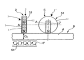
- FIG. 1 shows a schematic representation of EMUS transducers having a permanent magnet and an eddy current coil with elliptically shaped strip conductor loops, attached to the circumferential edge of a rolling member;
- FIG. 2 shows a schematic representation of an EMUS transducer having a permanent magnet and an eddy current coil with a strip conductor windings at the circumferential edge of a rolling member;
- FIG. 3 shows a schematic representation of an EMUS transducer having a permanent magnet and two ferromagnetic return paths
- FIGS. 4 and 5 show a view of an EMUS transducer having two permanent magnets and an eddy current coil
- FIGS. 6 and 7 show a representation of an EMUS transducer having an electromagnet and a separate eddy current coil
- FIGS. 8 a and b show a prior art EMUS transducer.
- the left representation in FIG. 1 shows a front view and the right representation shows a lateral view, of the EMUS transducer according to the present invention, which due to its principle of construction is also referred to as an EMUS wheel.
- the EMUS transducer is provided with a rolling member 5 which in the preferred embodiment is designed to be a ring or reel which is hollow inside and has an outer circumferential edge 51 .
- the rolling member 5 has a center axis of rotation A about which the rolling member 5 rolls relative to the technical surface 6 of the test object 4 .
- An eddy current coil 2 is wound along the circumferential edge 51 of the rolling member 5 as shown in the left representation.
- the eddy current coil 2 comprises a through-going electrical conductor including elliptical strip conductor loops 52 which are wrapped along the circumferential edge 51 of the rolling member 5 in such a manner that the entire circumferential edge 51 of rolling member 5 is covered by the loops 52 . It is obvious that when the current is applied to the strip conductors 52 , two immediately adjacent strip conductor loops 52 have current flowing in opposite directions.
- the alternative strip conductors 52 ′ are wound on the circumferential so that two strip conductors wound immediately adjacent to each other extend in the same direction.
- the strip conductor 52 and 52 ′ are each suited for effectively coupling in ultrasonic waves into the test object 4 .
- Each EMUS transducer shown in FIG. 1 is provided with a permanent magnet 7 to introduce a temporally constant magnetic field into the test object.
- the permanent magnet 7 is attached to the axis of rotation A in such an asymmetrical manner that a magnetic pole, preferably the magnetic north pole N is disposed maximally close to the circumferential edge 51 of the rolling member 5 .
- the magnetic north pole N of the permanent magnet 7 is drawn to the ferromagnetic test object 4 and, due to its rotational mobility, about the axis of rotation A always stays facing the test object 4 , so that the magnetic north pole is always directed downward.
- the permanent magnet 7 generates a magnetic field whose magnetic field lines are always oriented perpendicular to the technical surface 6 of the test object 4 .
- eddy current coil 2 If the eddy current coil 2 is fed with pulsed current, eddy currents are induced in the test object which interact with the magnetic flow oriented normally to the technical surface 6 .
- Ultrasonic waves with circular polarization are generated in test object 4 by developing Lorenz forces. The ultrasonic waves propagate essentially perpendicular to the technical surface 6 inside the test object 4 .
- the eddy current coil 2 also functions as a reception coil for the ultrasonic waves reflected back inside the test object 4 .
- FIG. 2 shows a variant of the EMUS transducer in which the eddy current coil 2 has electrical windings 53 which are each disposed around the circumferential edge 51 of the rolling member 5 .
- the design of the strip conductors 53 of the current coil 2 is shown in the left representation of FIG. 2 . Due to the alternative embodiment of the strip conductors 53 according to the preferred embodiment in FIG. 2 , ultrasonic waves with linear polarization are generated in the test object 4 . The ultrasonic waves however are due to the same excitation principle by Lorenz forces occurring as in the preferred embodiment according to FIG. 1 .
- the rolling member 5 is preferably not a metallic material.
- the rolling member 5 can, of course, also be made of a ferromagnetic and electrically conductive material. In this case, however, care must be taken that the strip conductors 52 or 53 of the eddy current coil 2 are electrically insulated from the rolling member 5 . It is also expedient, for further reduction of the rolling friction occurring between the rolling member 5 and the technical surface 6 , to provide a protective coat (not depicted) to protect the eddy current coils 52 or 53 .
- FIG. 3 shows again in the left representation, a front view and in the right representation, a lateral view of the EMUS transducer 3 .
- the strip conductors of the eddy current coil 2 are wound around the surface of a cylindrical or rod-shaped permanent magnet 7 .
- the disk rolling members 5 Attached at the opposite N and S magnetic poles of the permanent magnet 7 are two disk rolling members 5 composed of ferromagnetic material, which is preferably a ferrosteel and which project radially outward from the axis of rotation of the permanent magnet 7 including the eddy current 2 .
- the disk rolling members 5 each act as a yoke which conducts the magnetic field lines so that a magnetic circuit including the ferromagnetic rolling members 5 and the test object is closed. Due to the magnetic return path, a magnetic field is coupled tangentially to the technical surface 6 inside test object 4 .
- the eddy currents excited by the eddy current coils 2 generate inside the test object 4 a secondary alternating magnetic field which overlaps with the constant magnetic field of the permanent magnet 7 .
- the ultrasonic waves are excited by the developing magnetostrictive effect and, like in the case of the embodiment according to FIG. 2 , have a linear polarization.
- the disk rolling members 5 which enclose the permanent magnet 7 on both sides, have two functions. On the one hand the rolling members 5 act as a magnetic yoke and on the other hand they permit the ultrasonic transducers to roll over the technical surface 6 of the test object 4 , with the eddy current coils 2 always assume a constant distance from the technical surface 6 , due to which the strip conductors are subject to no mechanical wear from rolling friction.
- FIGS. 4 and 5 show two further preferred embodiments of an EMUS transducer 3 according to the invention. These embodiments are provided with two permanent magnets 7 and 7 ′ and an eddy current coil 2 . The only difference in the designs of the two embodiments is in the eddy current coils 2 .
- the permanent magnets 7 and 7 ′ are attached with their opposing magnetic north poles N to the ferromagnetic rolling member 5 , which preferably is a ring or a wheel. Due to the opposite magnetic north poles N, a displacement of the magnetic field lines occurs in such a manner that they are coupled, via the ferromagnetic ring unit rolling member 5 , perpendicular to the technical surface 6 of the test object 4 .
- the ferromagnetic rolling member 5 acts simultaneously as a concentrator of the magnetic field by which the magnetic field at the contact points between the rolling member 5 and the technical surface 6 is coupled into the test object 4 in a concentrated manner.
- the ultrasonic-wave excitation principle is the same as in the preferred embodiments in FIGS. 1 and 2 .
- a ferromagnetic end piece may be provided on the front magnetic south poles, which like the rolling member 5 comes into contact with the technical surface 6 of the test object 4 .
- both the electromagnet array 7 and the rolling member 5 are located on a common technical surface 6 of the test object 4 .
- the excitation principle of the ultrasonic waves inside the test object 4 is identical to that according to the preferred embodiment in FIG. 3 .
- the tangentially running magnetic field which is fed by the electromagnet 7 into the test object 4 interacts with the eddy currents and the alternating magnetic field in such a manner that, due to the occurrence of magnetostrictive effects, linear polarized ultrasonic waves are generated.
- eddy current coils 2 designed as rolling members 5 , can be provided in the area of the tangential magnetic field.
- wear of the EMUS transducer is minimal.
- the invention also referred to as EMUS wheel, is fundamentally suitable for an application to different fields such as for measuring the wall thickness and fault inspection of sheet metals, rails, pipes and pipelines as well as railroad wheels, oil containers or the outer walls of ships and other security containers.
- the EMUS transducer can also be combined with transport systems, for example so-called pig systems used in long-distant pipelines and the like to perform inspection.
Landscapes
- Chemical & Material Sciences (AREA)
- Physics & Mathematics (AREA)
- Biochemistry (AREA)
- Life Sciences & Earth Sciences (AREA)
- Health & Medical Sciences (AREA)
- Analytical Chemistry (AREA)
- General Health & Medical Sciences (AREA)
- General Physics & Mathematics (AREA)
- Immunology (AREA)
- Pathology (AREA)
- Electromagnetism (AREA)
- Chemical Kinetics & Catalysis (AREA)
- Electrochemistry (AREA)
- Investigating Or Analyzing Materials By The Use Of Ultrasonic Waves (AREA)
- Investigating Or Analyzing Materials By The Use Of Magnetic Means (AREA)
Applications Claiming Priority (4)
| Application Number | Priority Date | Filing Date | Title |
|---|---|---|---|
| DE102004054423.9 | 2004-11-10 | ||
| DE102004054423 | 2004-11-10 | ||
| DE102004054423A DE102004054423B3 (de) | 2004-11-10 | 2004-11-10 | Vorrichtung zur Materialprüfung und/oder Dickenmessung an einem wenigstens elektrisch leitende und ferromagnetische Materialanteile aufweisenden Prüfobjekt |
| PCT/EP2005/011949 WO2006050914A1 (fr) | 2004-11-10 | 2005-11-08 | Dispositif d'essai de matiere acoustique electromagnetique et/ou de mesure d'epaisseur sur un objet a tester presentant au moins une partie de matiere electroconductrice et ferromagnetique au moyen d'une roue de test |
Publications (2)
| Publication Number | Publication Date |
|---|---|
| US20080276711A1 US20080276711A1 (en) | 2008-11-13 |
| US8079266B2 true US8079266B2 (en) | 2011-12-20 |
Family
ID=35559437
Family Applications (1)
| Application Number | Title | Priority Date | Filing Date |
|---|---|---|---|
| US11/718,911 Expired - Fee Related US8079266B2 (en) | 2004-11-10 | 2005-11-08 | Device for testing material and measuring thickness on a test object having at least electrically conducting and ferromagnetic material parts |
Country Status (6)
| Country | Link |
|---|---|
| US (1) | US8079266B2 (fr) |
| EP (1) | EP1810018A1 (fr) |
| CA (1) | CA2584471C (fr) |
| DE (1) | DE102004054423B3 (fr) |
| NO (1) | NO20071885L (fr) |
| WO (1) | WO2006050914A1 (fr) |
Cited By (3)
| Publication number | Priority date | Publication date | Assignee | Title |
|---|---|---|---|---|
| US20110259108A1 (en) * | 2008-10-24 | 2011-10-27 | Institut Dr. Foerster Gmbh & Co. Kg | Electromagnetic-acoustic transducer and ultrasonic test system having the same |
| US20120055251A1 (en) * | 2010-09-02 | 2012-03-08 | Hitachi, Ltd. | Ultrasonic Testing Method |
| US20180164256A1 (en) * | 2016-12-12 | 2018-06-14 | Southwest Research Institute | Non Destructive Magnetostrictive Testing With Unidirectional Guided Waves Generated By Ferromagnetic Strip Sensor |
Families Citing this family (13)
| Publication number | Priority date | Publication date | Assignee | Title |
|---|---|---|---|---|
| ES2339386T3 (es) * | 2005-08-10 | 2010-05-19 | De La Rue International Limited | Sistema de inspeccion de documentos ultrasonico. |
| WO2008003972A1 (fr) * | 2006-07-05 | 2008-01-10 | University Of Warwick | Dispositif de génération de courant de foucault, appareil et procédé |
| PL2100072T3 (pl) * | 2006-12-21 | 2019-07-31 | Athena Industrial Technologies Inc. | Przyrząd i sposób kontroli liniowej struktury |
| FR2950434B1 (fr) * | 2009-09-24 | 2011-11-25 | Electricite De France | Perfectionnements a la detection de depots comportant au moins un materiau ferromagnetique sur ou a proximite de la paroi externe d'un tube |
| JP5293719B2 (ja) * | 2010-10-01 | 2013-09-18 | 東京エレクトロン株式会社 | 基板処理装置のデータ取得方法及びセンサ用基板 |
| DE102011015677A1 (de) * | 2011-03-31 | 2012-10-04 | Rosen Swiss Ag | Akustischer Durchflussmesser |
| RU2465574C1 (ru) * | 2011-06-17 | 2012-10-27 | Государственное образовательное учреждение высшего профессионального образования "Южно-Российский государственный университет экономики и сервиса" (ГОУ ВПО "ЮРГУЭС") | Способ электромагнитного контроля механической прочности муфтовых соединений труб в скважинах |
| DE102012019217B4 (de) | 2012-10-01 | 2014-08-07 | Rosen Swiss Ag | Akustischer Durchflussmesser und Verfahren zur Bestimmung des Flusses in einem Objekt |
| BR112018003658B1 (pt) * | 2015-08-31 | 2022-03-15 | Jrb Engineering Pty Ltd | Método e sistema para detectar uma descontinuidade de material em um artigo magnetizável |
| CN112212900A (zh) * | 2020-09-29 | 2021-01-12 | 刘翡琼 | 一种低成本高灵敏度超声波探测器 |
| CN114653569A (zh) * | 2022-02-28 | 2022-06-24 | 零声科技(苏州)有限公司 | 交替永磁阵列式换能器封装装置 |
| CN115235390B (zh) * | 2022-05-26 | 2023-07-25 | 国网安徽省电力有限公司亳州供电公司 | 耐候钢锈层厚度检测方法及系统 |
| CN118328829B (zh) * | 2024-06-12 | 2024-08-13 | 兴化市万达电力工具有限公司 | 一种高压电缆绝缘层厚度检测装置 |
Citations (9)
| Publication number | Priority date | Publication date | Assignee | Title |
|---|---|---|---|---|
| US3668517A (en) * | 1970-07-30 | 1972-06-06 | United States Steel Corp | Magnetic particle inspection apparatus wherein the accumulated particles close the indicator circuit |
| US3697867A (en) | 1969-06-19 | 1972-10-10 | Cavitron Corp | Vibration sensor utilizing eddy currents induced in member vibrating in the field of a magnet |
| US3771354A (en) | 1971-12-06 | 1973-11-13 | Rockwell International Corp | Rapid ultrasonic inspection apparatus |
| US4164873A (en) * | 1976-09-28 | 1979-08-21 | Hoesch Werke Aktiengesellschaft | Method of and device for material checking by ultra sound while employing an electrodynamic sound converter |
| GB1561811A (en) | 1975-10-08 | 1980-03-05 | Lamb W C | Method and apparatus for ultrasonic inspection |
| US4898034A (en) | 1988-08-23 | 1990-02-06 | The United States Of America As Represented By The Department Of Energy | High temperature ultrasonic testing of materials for internal flaws |
| EP0722085A1 (fr) * | 1995-01-14 | 1996-07-17 | Fraunhofer-Gesellschaft Zur Förderung Der Angewandten Forschung E.V. | Dispositif de contrÔle ultrasonique |
| JPH11133003A (ja) | 1997-10-28 | 1999-05-21 | Osaka Gas Co Ltd | Ppm電磁超音波トランスジューサとppm電磁超音波トランスジューサを用いた探傷装置及び探傷方法 |
| US7024935B2 (en) * | 2002-02-05 | 2006-04-11 | Pii Limited | Electromagnetic acoustic transducers |
Family Cites Families (1)
| Publication number | Priority date | Publication date | Assignee | Title |
|---|---|---|---|---|
| DE3511076A1 (de) * | 1985-03-27 | 1986-10-09 | Kopp AG International Pipeline Services, 4450 Lingen | Molch fuer elektromagnetische pruefungen an rohrleitungswandungen aus stahl sowie verfahren hierzu |
-
2004
- 2004-11-10 DE DE102004054423A patent/DE102004054423B3/de not_active Expired - Fee Related
-
2005
- 2005-11-08 US US11/718,911 patent/US8079266B2/en not_active Expired - Fee Related
- 2005-11-08 WO PCT/EP2005/011949 patent/WO2006050914A1/fr not_active Ceased
- 2005-11-08 EP EP05810918A patent/EP1810018A1/fr not_active Withdrawn
- 2005-11-08 CA CA2584471A patent/CA2584471C/fr not_active Expired - Fee Related
-
2007
- 2007-04-12 NO NO20071885A patent/NO20071885L/no not_active Application Discontinuation
Patent Citations (9)
| Publication number | Priority date | Publication date | Assignee | Title |
|---|---|---|---|---|
| US3697867A (en) | 1969-06-19 | 1972-10-10 | Cavitron Corp | Vibration sensor utilizing eddy currents induced in member vibrating in the field of a magnet |
| US3668517A (en) * | 1970-07-30 | 1972-06-06 | United States Steel Corp | Magnetic particle inspection apparatus wherein the accumulated particles close the indicator circuit |
| US3771354A (en) | 1971-12-06 | 1973-11-13 | Rockwell International Corp | Rapid ultrasonic inspection apparatus |
| GB1561811A (en) | 1975-10-08 | 1980-03-05 | Lamb W C | Method and apparatus for ultrasonic inspection |
| US4164873A (en) * | 1976-09-28 | 1979-08-21 | Hoesch Werke Aktiengesellschaft | Method of and device for material checking by ultra sound while employing an electrodynamic sound converter |
| US4898034A (en) | 1988-08-23 | 1990-02-06 | The United States Of America As Represented By The Department Of Energy | High temperature ultrasonic testing of materials for internal flaws |
| EP0722085A1 (fr) * | 1995-01-14 | 1996-07-17 | Fraunhofer-Gesellschaft Zur Förderung Der Angewandten Forschung E.V. | Dispositif de contrÔle ultrasonique |
| JPH11133003A (ja) | 1997-10-28 | 1999-05-21 | Osaka Gas Co Ltd | Ppm電磁超音波トランスジューサとppm電磁超音波トランスジューサを用いた探傷装置及び探傷方法 |
| US7024935B2 (en) * | 2002-02-05 | 2006-04-11 | Pii Limited | Electromagnetic acoustic transducers |
Non-Patent Citations (1)
| Title |
|---|
| Clark, R.: "Rail Flaw Detection: Overview and Needs for Future Developments", NDT & E International, Butterworth-Heinemann, Oxford, GB, vol. 37, No. 2, Mar. 2004, pp. 111-118, XP004481709, ISSN: 0963-8695. |
Cited By (6)
| Publication number | Priority date | Publication date | Assignee | Title |
|---|---|---|---|---|
| US20110259108A1 (en) * | 2008-10-24 | 2011-10-27 | Institut Dr. Foerster Gmbh & Co. Kg | Electromagnetic-acoustic transducer and ultrasonic test system having the same |
| US8789422B2 (en) * | 2008-10-24 | 2014-07-29 | Institut Dr. Foerster Gmbh & Co. Kg | Electromagnetic-acoustic transducer and ultrasonic test system having the same |
| US20120055251A1 (en) * | 2010-09-02 | 2012-03-08 | Hitachi, Ltd. | Ultrasonic Testing Method |
| US9046469B2 (en) * | 2010-09-02 | 2015-06-02 | Mitsubishi Hitachi Power Systems, Ltd. | Ultrasonic testing method |
| US20180164256A1 (en) * | 2016-12-12 | 2018-06-14 | Southwest Research Institute | Non Destructive Magnetostrictive Testing With Unidirectional Guided Waves Generated By Ferromagnetic Strip Sensor |
| US10466206B2 (en) * | 2016-12-12 | 2019-11-05 | Southwest Research Institute | Non destructive magnetostrictive testing with unidirectional guided waves generated by ferromagnetic strip sensor |
Also Published As
| Publication number | Publication date |
|---|---|
| CA2584471C (fr) | 2014-07-08 |
| NO20071885L (no) | 2007-06-01 |
| EP1810018A1 (fr) | 2007-07-25 |
| US20080276711A1 (en) | 2008-11-13 |
| DE102004054423B3 (de) | 2006-05-04 |
| CA2584471A1 (fr) | 2006-05-18 |
| WO2006050914A1 (fr) | 2006-05-18 |
Similar Documents
| Publication | Publication Date | Title |
|---|---|---|
| US8079266B2 (en) | Device for testing material and measuring thickness on a test object having at least electrically conducting and ferromagnetic material parts | |
| US5461313A (en) | Method of detecting cracks by measuring eddy current decay rate | |
| US5532587A (en) | Magnetic field analysis method and apparatus for determining stress characteristics in a pipeline | |
| US6424150B2 (en) | Magnetostrictive sensor rail inspection system | |
| CA2585823C (fr) | Procede et dispositif de controle electromagnetique et acoustique de materiaux et/ou de mesure d'epaisseur de materiaux sur un objet de controle comportant des elements de materiaux au moins electriquement conducteurs et ferromagnetiques | |
| US6294912B1 (en) | Method and apparatus for nondestructive inspection of plate type ferromagnetic structures using magnetostrictive techniques | |
| JP2681673B2 (ja) | 平面探傷用交流漏洩磁束探傷装置 | |
| US20040221652A1 (en) | Transducer guided wave electromagnetic acoustic | |
| CN101261246A (zh) | 管道裂纹远场涡流检测方法 | |
| CN108226277A (zh) | 一种漏磁、电磁超声和涡流复合式管道外检测探头 | |
| JPH11502020A (ja) | 磁気歪センサーを用いたパイプ及びチューブの非破壊評価 | |
| WO2002033398A1 (fr) | Capteur de fuites magnetiques d"un appareil de penetration magnetique | |
| US6707296B2 (en) | Method for detecting cracks in electrically conducting material | |
| Park et al. | Enhanced detection of defects using GMR sensor based remote field eddy current technique | |
| US20030034776A1 (en) | Method and facility for storing and indexing web browsing data | |
| FR3013844A1 (fr) | Dispositif pour le controle non destructif d'un objet a controler | |
| RU2661312C1 (ru) | Способ бесконтактного неразрушающего контроля и устройство для его осуществления | |
| RU2680103C2 (ru) | Магнитная система сканера-дефектоскопа | |
| Nestleroth | Implementing current in-line inspection technologies on crawler systems | |
| JP2591188B2 (ja) | 電磁気特性検出方法及び装置 | |
| JPS5935807Y2 (ja) | 渦流探傷装置 | |
| JPH0342629B2 (fr) | ||
| JP2018054301A (ja) | 漏洩磁束探傷装置 | |
| JPH08278289A (ja) | 強磁性管の探傷装置および探傷方法 | |
| JP2004028638A (ja) | 鋼帯の耳割れ検出方法及び装置 |
Legal Events
| Date | Code | Title | Description |
|---|---|---|---|
| AS | Assignment |
Owner name: FRAUNHOFER-GESELLSCHAFT ZUR FORDERRUNG DER ANGEWAN Free format text: ASSIGNMENT OF ASSIGNORS INTEREST;ASSIGNORS:NICHIFORENCO, JORJ;BULAVINOV, ANDREI;KRONING, MICHAEL;REEL/FRAME:020629/0747;SIGNING DATES FROM 20070424 TO 20070525 Owner name: FRAUNHOFER-GESELLSCHAFT ZUR FORDERRUNG DER ANGEWAN Free format text: ASSIGNMENT OF ASSIGNORS INTEREST;ASSIGNORS:NICHIFORENCO, JORJ;BULAVINOV, ANDREI;KRONING, MICHAEL;SIGNING DATES FROM 20070424 TO 20070525;REEL/FRAME:020629/0747 |
|
| AS | Assignment |
Owner name: FRAUNHOFER-GESELLSCHAFT ZUR FORDERUNG DER ANGEWAND Free format text: CORRECTIVE ASSIGNMENT TO CORRECT ASSIGNOR AND ASSIGNEE, PREVIOUSLY RECORDED AT REEL 020269, FRAME 0747;ASSIGNORS:NICHIFORENCO, JORJ;BULAVINOV, ANDREY;KRONING, MICHAEL;REEL/FRAME:021048/0389;SIGNING DATES FROM 20070424 TO 20070525 Owner name: FRAUNHOFER-GESELLSCHAFT ZUR FORDERUNG DER ANGEWAND Free format text: CORRECTIVE ASSIGNMENT TO CORRECT ASSIGNOR AND ASSIGNEE, PREVIOUSLY RECORDED AT REEL 020269, FRAME 0747;ASSIGNORS:NICHIFORENCO, JORJ;BULAVINOV, ANDREY;KRONING, MICHAEL;SIGNING DATES FROM 20070424 TO 20070525;REEL/FRAME:021048/0389 |
|
| AS | Assignment |
Owner name: FRAUNHOFER-GESELLSCHAFT ZUR FORDERUNG DER ANGEWAND Free format text: CORRECTIVE ASSIGNMENT TO CORRECT THE ORIGINAL COVER SHEET, THE 2ND ASSIGNOR'S NAME IS INCORRECT, PREVIOUSLY RECORDED ON REEL 021048 FRAME 0389. ASSIGNOR(S) HEREBY CONFIRMS THE ASSIGNMENT;ASSIGNORS:NICHIFORENCO, JORJ;BULAVINOV, ANDREI;KRONING, MICHAEL;SIGNING DATES FROM 20070424 TO 20070525;REEL/FRAME:026806/0207 |
|
| FEPP | Fee payment procedure |
Free format text: PAYOR NUMBER ASSIGNED (ORIGINAL EVENT CODE: ASPN); ENTITY STATUS OF PATENT OWNER: LARGE ENTITY |
|
| REMI | Maintenance fee reminder mailed | ||
| LAPS | Lapse for failure to pay maintenance fees | ||
| STCH | Information on status: patent discontinuation |
Free format text: PATENT EXPIRED DUE TO NONPAYMENT OF MAINTENANCE FEES UNDER 37 CFR 1.362 |
|
| STCH | Information on status: patent discontinuation |
Free format text: PATENT EXPIRED DUE TO NONPAYMENT OF MAINTENANCE FEES UNDER 37 CFR 1.362 |
|
| FP | Lapsed due to failure to pay maintenance fee |
Effective date: 20151220 |