US8416751B2 - Method and apparatus used for airlink communications - Google Patents
Method and apparatus used for airlink communications Download PDFInfo
- Publication number
- US8416751B2 US8416751B2 US11/759,887 US75988707A US8416751B2 US 8416751 B2 US8416751 B2 US 8416751B2 US 75988707 A US75988707 A US 75988707A US 8416751 B2 US8416751 B2 US 8416751B2
- Authority
- US
- United States
- Prior art keywords
- address
- airlink
- access terminal
- network device
- packet
- Prior art date
- Legal status (The legal status is an assumption and is not a legal conclusion. Google has not performed a legal analysis and makes no representation as to the accuracy of the status listed.)
- Expired - Fee Related, expires
Links
Images




Classifications
-
- H—ELECTRICITY
- H04—ELECTRIC COMMUNICATION TECHNIQUE
- H04L—TRANSMISSION OF DIGITAL INFORMATION, e.g. TELEGRAPHIC COMMUNICATION
- H04L9/00—Cryptographic mechanisms or cryptographic arrangements for secret or secure communications; Network security protocols
- H04L9/40—Network security protocols
-
- H—ELECTRICITY
- H04—ELECTRIC COMMUNICATION TECHNIQUE
- H04L—TRANSMISSION OF DIGITAL INFORMATION, e.g. TELEGRAPHIC COMMUNICATION
- H04L61/00—Network arrangements, protocols or services for addressing or naming
- H04L61/09—Mapping addresses
- H04L61/10—Mapping addresses of different types
- H04L61/103—Mapping addresses of different types across network layers, e.g. resolution of network layer into physical layer addresses or address resolution protocol [ARP]
-
- H—ELECTRICITY
- H04—ELECTRIC COMMUNICATION TECHNIQUE
- H04L—TRANSMISSION OF DIGITAL INFORMATION, e.g. TELEGRAPHIC COMMUNICATION
- H04L45/00—Routing or path finding of packets in data switching networks
- H04L45/54—Organization of routing tables
-
- H—ELECTRICITY
- H04—ELECTRIC COMMUNICATION TECHNIQUE
- H04L—TRANSMISSION OF DIGITAL INFORMATION, e.g. TELEGRAPHIC COMMUNICATION
- H04L2101/00—Indexing scheme associated with group H04L61/00
- H04L2101/60—Types of network addresses
- H04L2101/604—Address structures or formats
-
- H—ELECTRICITY
- H04—ELECTRIC COMMUNICATION TECHNIQUE
- H04L—TRANSMISSION OF DIGITAL INFORMATION, e.g. TELEGRAPHIC COMMUNICATION
- H04L2101/00—Indexing scheme associated with group H04L61/00
- H04L2101/60—Types of network addresses
- H04L2101/672—Short addresses
-
- H—ELECTRICITY
- H04—ELECTRIC COMMUNICATION TECHNIQUE
- H04W—WIRELESS COMMUNICATION NETWORKS
- H04W88/00—Devices specially adapted for wireless communication networks, e.g. terminals, base stations or access point devices
- H04W88/08—Access point devices
Definitions
- the present invention is directed to methods and apparatus for communications, and more particularly to methods and apparatus related to routing of packets.
- Wireless communications systems often include a plurality of access points (APs) and/or other network elements in addition to access terminals, e.g., mobile or other end node devices.
- access terminals normally communicate with access points via wireless communications links while other elements in the network, e.g., APs, generally communicate via non-air links, e.g., fiber, cable or wire links.
- non-air links e.g., fiber, cable or wire links.
- bandwidth is a valuable constrained resource. Accordingly, it is desirable that communication over the airlink be performed in an efficient manner without excessive overhead.
- Communications links between access points and/or other network devices are often less constrained from a bandwidth perspective than are air links between access terminals and access points. Accordingly, more overhead in terms of address length and/or other information may be acceptable over backhaul links than over an airlink.
- IP Internet Protocol
- serving devices may be assigned specific addresses which are interpreted based on the source of the communication, e.g., MAC (Media Access Control) packet, in which the address is used.
- addresses may be interpreted as being of a different type than other addresses which can be interpreted and/or used without taking into account the identity of the sender.
- IAPs Internet Attachment Points
- airlink IAP address an address value, referred to as an airlink IAP address. This value is the same for one or more ATs but is interpreted at an AP receiving such IAP address based on information corresponding to the AT which sent the packet including the IAP address.
- the IAP address may be implemented as a special address type that can be used by an AT to identify an AP which is the Internet attachment point for the AT sending the packet including the IAP address.
- the IAP address is very short, e.g., 3 or fewer bits.
- the IAP address is implemented as an address type indicator where the Address type indicator indicates that the address is of an IAP type. In such a case, no bits are needed beyond that used to indicate the type of address.
- an IAP address of the type described By using an IAP address of the type described, a relatively short address can be sent over the airlink when a mobile device is attempting to communicate with its IAP as opposed to embodiments where a full IP address of the IAP is sent over the airlink.
- the AP receiving a packet e.g., mac packet
- the short IAP address may be mapped to the long, e.g., full IP address, of the IAP serving the AT which sent the packet.
- the determined address of the IAP server is then combined with the payload of the received packet and sent to the IAP corresponding to the AT.
- the mapping may be different since the set of information corresponding to the different ATs may indicate different IAP addresses.
- the IAP address information corresponding to different ATs may be updated based on information communicated from one or more devices in the network to the APs. For example, the information may be communicated as part of a set of active AP information maintained for each AT and which is communicated to, or accessible by, APs serving an AT. Alternatively, IAPs may provide APs information about which ATs they are serving at a given time. In addition or as an alternative, an AT may indicate to a current serving AP via a message sent over an airlink, the full address of the IAP which is serving the AP at a particular point in time. The IAP address is then stored and used for the AT until a new IAP address is supplied or the AT ceases to use the AP.
- an AT and AP can communicate over the airlink using fewer bits to identify an IAP corresponding to the AT than would be required if a long address, e.g., the full IP address of the destination device, was used for communications over an airlink between a serving AP and an AT.
- a long address e.g., the full IP address of the destination device
- An exemplary method of operating an access point comprises: receiving from an airlink, a first packet communicated from an access terminal, the first packet including information to be communicated to a network device and a predefined airlink address corresponding to said network device, said network device having an IP address which is longer than said predetermined airlink address; and determining an IP address corresponding to said predefined airlink address from information mapping between predefined airlink addresses and IP addresses.
- Another exemplary method of operating an access point comprises: receiving from a communications link with a network device, a first packet including information to be communicated to an access terminal and a network device IP address indicating the source of the information; and determining a predefined airlink address corresponding to said network device address from information mapping between predefined airlink addresses and IP addresses, said predefined airlink address being shorter than said IP address.
- An exemplary access point includes: a wireless receiver for receiving from an airlink, a first packet communicated from an access terminal, the first packet including information to be communicated to a network device and a predefined airlink address corresponding to said network device, said network device having an IP address which is longer than said predetermined airlink address; and an IP address determination module for determining an IP address corresponding to said predefined airlink address from information mapping between predefined airlink addresses and IP addresses.
- An exemplary method of operating an access terminal to communicate information comprises: generating a packet, said packet including a predetermined airlink address corresponding to a network device, said network device having an IP address which is longer than said predetermined airlink address and information to be communicated to said network device; and transmitting said generated packet over an airlink to an access point.
- Another exemplary method of operating an access terminal comprises: receiving a packet, said packet including a predetermined airlink address corresponding to a network device, said network device having an IP address which is longer than said predetermined airlink address and information to be communicated to said access terminal; and determining from stored address information and said predetermined airlink address included in said received packet, the network device which is the source of information included in said received packet.
- An exemplary access terminal comprises: a packet generation module for generating packets, said packets including information to be communicated to a network device and a predetermined airlink address corresponding to said network device, said network device having an IP address which is longer than said predetermined airlink address; and a wireless transmitter for transmitting said generated packets over an airlink to an access point.
- FIG. 1 illustrates a multiple access wireless communication system according to one embodiment.
- FIG. 2 is a block diagram of an exemplary communication system.
- FIG. 3 illustrates an exemplary network including a distributed access network (AN) architecture and an access terminal (AT).
- AN distributed access network
- AT access terminal
- FIG. 4 illustrates an exemplary network including a centralized AN architecture and an AT.
- FIG. 5 is a flowchart of an exemplary method of operating an access point in accordance with various embodiments.
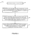
- FIG. 6 is a flowchart of an exemplary method of operating an access point in accordance with various embodiments.
- FIG. 7 is a drawing of an exemplary access point in accordance with various embodiments.
- FIG. 8 is a flowchart of an exemplary method of operating an access terminal to communicate information.
- FIG. 9 is a flowchart of an exemplary method of operating an access terminal in accordance with various embodiments.
- FIG. 10 is a drawing of an exemplary access terminal in accordance with various embodiments.
- Wireless communication systems are widely deployed to provide various types of communication content such as voice, data, and so on. These systems may be multiple-access systems capable of supporting communication with multiple users by sharing the available system resources (e.g., bandwidth and transmit power). Examples of such multiple-access systems include World Interoperability for Microwave Access (WiMAX), infrared protocols such as Infrared Data Association (IrDA), short-range wireless protocols/technologies, Bluetooth® technology, ZigBee® protocol, ultra wide band (UWB) protocol, home radio frequency (HomeRF), shared wireless access protocol (SWAP), wideband technology such as a wireless Ethernet compatibility alliance (WECA), wireless fidelity alliance (Wi-Fi Alliance), 802.11 network technology, public switched telephone network technology, public heterogeneous communications network technology such as the Internet, private wireless communications network, land mobile radio network, code division multiple access (CDMA), wideband code division multiple access (WCDMA), universal mobile telecommunications system (UMTS), advanced mobile phone service (AMPS), time division multiple access (TDMA), frequency division multiple access (
- a wireless multiple-access communication system can simultaneously support communication for multiple wireless terminals.
- Each terminal communicates with one or more base stations via transmissions on the forward and reverse links.
- the forward link (or downlink) refers to the communication link from the base stations to the terminals
- the reverse link (or uplink) refers to the communication link from the terminals to the base stations.
- This communication link may be established via a single-in-single-out, multiple-in-signal-out or a multiple-in-multiple-out (MIMO) system.
- MIMO multiple-in-multiple-out
- An access point 100 includes multiple antenna groups, one including 104 and 106 , another including 108 and 110 , and an additional including 112 and 114 . In FIG. 1 , only two antennas are shown for each antenna group, however, more or fewer antennas may be utilized for each antenna group.
- Access terminal 116 is in communication with antennas 112 and 114 , where antennas 112 and 114 transmit information to access terminal 116 over forward link 120 and receive information from access terminal 116 over reverse link 118 .
- Access terminal 122 is in communication with antennas 106 and 108 , where antennas 106 and 108 transmit information to access terminal 122 over forward link 126 and receive information from access terminal 122 over reverse link 124 .
- communication links 118 , 120 , 124 and 126 may use different frequencies for communication.
- forward link 120 may use a different frequency then that used by reverse link 118 .
- antenna groups each are designed to communicate to access terminals in a sector of the areas covered by access point 100 .
- the transmitting antennas of access point 100 utilize beamforming in order to improve the signal-to-noise ratio of forward links for the different access terminals 116 and 122 . Also, an access point using beamforming to transmit to access terminals scattered randomly through its coverage causes less interference to access terminals in neighboring cells than an access point transmitting through a single antenna to all its access terminals.
- An access point may be a fixed station used for communicating with the terminals and may also be referred to as an access node, a Node B, a base station or some other terminology.
- An access terminal may also be called an access device, user equipment (UE), a wireless communication device, terminal, wireless terminal, mobile terminal, mobile node, end node or some other terminology.
- UE user equipment
- FIG. 2 is a block diagram of an embodiment of an exemplary access point 210 and an exemplary access terminal 250 in a MIMO system 200 .
- traffic data for a number of data streams is provided from a data source 212 to a transmit (TX) data processor 214 .
- TX transmit
- the coded data for each data stream may be multiplexed with pilot data using OFDM techniques.
- the pilot data is typically a known data pattern that is processed in a known manner and may be used at the receiver system to estimate the channel response.
- the multiplexed pilot and coded data for each data stream is then modulated (i.e., symbol mapped) based on a particular modulation scheme (e.g., BPSK, QSPK, M-PSK, or M-QAM) selected for that data stream to provide modulation symbols.
- the data rate, coding, and modulation for each data stream may be determined by instructions performed by processor 230 .
- TX MIMO processor 220 The modulation symbols for each of the data streams are then provided to a TX MIMO processor 220 , which may further process the modulation symbols (e.g., for OFDM). TX MIMO processor 220 then provides N T modulation symbol streams to N T transmitters (TMTR) 222 a through 222 t . In certain embodiments, TX MIMO processor 220 applies beamforming weights to the symbols of the data streams and to the antenna from which the symbol is being transmitted.
- Each transmitter receives and processes a respective symbol stream to provide one or more analog signals, and further conditions (e.g., amplifies, filters, and upconverts) the analog signals to provide a modulated signal suitable for transmission over the MIMO channel.
- N T modulated signals from transmitters 222 a through 222 t are then transmitted from N T antennas 224 a through 224 t , respectively.
- the transmitted modulated signals are received by N R antennas 252 a through 252 r and the received signal from each antenna 252 is provided to a respective receiver (RCVR) 254 a through 254 r .
- Each receiver ( 254 a , . . . , 254 r ) conditions (e.g., filters, amplifies, and downconverts) a respective received signal, digitizes the conditioned signal to provide samples, and further processes the samples to provide a corresponding “received” symbol stream.
- An RX data processor 260 then receives and processes the N R received symbol streams from N R receivers ( 254 a , . . . , 254 r ) based on a particular receiver processing technique to provide N T “detected” symbol streams.
- the RX data processor 260 then demodulates, deinterleaves, and decodes each detected symbol stream to recover the traffic data for the data stream.
- the processing by RX data processor 260 is complementary to that performed by TX MIMO processor 220 and TX data processor 214 at transmitter system 210 .
- a processor 270 periodically determines which pre-coding matrix to use (discussed below). Processor 270 formulates a reverse link message comprising a matrix index portion and a rank value portion.
- the reverse link message may comprise various types of information regarding the communication link and/or the received data stream.
- the reverse link message is then processed by a TX data processor 238 , which also receives traffic data for a number of data streams from a data source 236 , modulated by a modulator 280 , conditioned by transmitters 254 a through 254 r , and transmitted, via antennas ( 252 a , 252 r ), respectively, back to access point 210 .
- the modulated signals from access terminal 250 are received by antennas 224 , conditioned by receivers 222 , demodulated by a demodulator 240 , and processed by a RX data processor 242 to extract the reverse link message transmitted by the receiver system 250 .
- Processor 230 determines which pre-coding matrix to use for determining the beamforming weights, then processes the extracted message.
- Memory 232 includes routines and data/information.
- Processors 230 , 220 and/or 242 execute the routines and uses the data/information in memory 232 to control the operation of the access point 210 and implement methods.
- Memory 272 includes routines and data/information.
- Processors 270 , 260 , and/or 238 execute the routines and uses the data/information in memory 272 to control the operation of the access terminal 250 and implement methods.
- SimpleRAN is designed to significantly simplify the communications protocols between the backhaul access network elements in a wireless radio access network, while providing fast handoff to accommodate the demands of low latency applications, such as VOIP, in fast changing radio conditions.
- the network comprises access terminals (AT) and an access network (AN).
- AT access terminals
- AN access network
- the AN supports both a centralized and distributed deployment.
- the network architectures for the centralized and distributed deployments are shown in FIG. 3 and FIG. 4 respectively.
- FIG. 3 illustrates an exemplary network 300 including a distributed AN 302 and an AT 303 .
- the AN 302 comprises access points (AP) and home agents (HA).
- AN 302 includes a plurality of access points (APa 304 , APb 306 , APc 308 ) and home agent 310 .
- AN 302 includes an IP cloud 312 .
- the APs ( 304 , 306 , 308 ) are coupled to the IP cloud via links ( 314 , 316 , 318 ), respectively.
- the IP cloud 312 is coupled to the HA 310 via link 320 .
- An AP includes a:
- AN 302 APa 304 includes NF 324 , TF 326 and TF 328 .
- AN 302 APb 306 includes NF 330 , TF 332 and TF 334 .
- AN 302 APc 308 includes NF 336 , TF 338 and TF 340 .
- An AT includes a:
- Exemplary AT 303 includes a plurality of Interfaces (I_a 342 , I_b 344 , I_c 346 ) and MN 348 .
- AT 303 can be, and sometimes is, coupled to AP_a 304 via wireless link 350 .
- AT 303 can be, and sometimes is, coupled to AP_b 306 via wireless link 352 .
- AT 303 can be, and sometimes is, coupled to AP_c 308 via wireless link 354 .
- FIG. 4 illustrates an exemplary network 400 including a distributed AN 402 and an AT 403 .
- NF is no longer logically associated with a single TF, so the AN comprises network functions, access points and home agents.
- Exemplary AN 402 includes a plurality of NFs ( 404 , 406 , 408 ), a plurality of APs (AP_a 410 , AP_b 412 , AP_c 414 ), HA 416 and IP cloud 418 .
- NF 404 is coupled to IP cloud 418 via link 420 .
- NF 406 is coupled to IP cloud 418 via link 422 .
- NF 408 is coupled to IP cloud 418 via link 424 .
- IP cloud 418 is coupled to HA 416 via link 426 .
- NF 404 is coupled to (AP_a 410 , AP_b 412 , AP_c 414 ) via links ( 428 , 430 , 432 ), respectively.
- NF 406 is coupled to (AP_a 410 , AP_b 412 , AP_c 414 ) via links ( 434 , 436 , 438 ), respectively.
- NF 408 is coupled to (AP_a 410 , AP_b 412 , AP_c 414 ) via links ( 440 , 442 , 444 ), respectively.
- AP_a 410 includes TF 462 and TF 464 .
- AP_b 412 includes TF 466 and TF 468 .
- AP_c 414 includes TF 470 and TF 472 .
- NF controller for an AT i.e., the NF communicating with an AT as a part of the active set, performs the functions of allocating, managing and tearing down resources for the TF at that AT. Therefore, multiple NFs may control resources at a single TF, although these resources are managed independently.
- NF 408 is acting as an IAP for AT 403 , as shown by the line 460 .
- Exemplary AT 403 includes a plurality of Interfaces (I_a 446 , I_b 448 , I_c 450 ) and MN 452 .
- AT 403 can be, and sometimes is, coupled to AP_a 410 via wireless link 454 .
- AT 403 can be, and sometimes is, coupled to AP_b 412 via wireless link 456 .
- AT 403 can be, and sometimes is, coupled to AP_c 414 via wireless link 458 .
- an AT obtains service from an AP by making an access attempt on an access channel of a particular sector (TF).
- the NF associated with the TF receiving the access attempt contacts the IAP that is the session master for the AT and retrieves a copy of the AT's session.
- the AT indicates the identity of the IAP by including an UATI in the access payload.
- the UATI may be used as an IP address to directly address the IAP, or may be used to look up the address of the IAP.
- the AT is assigned air interface resources such as a MAC ID and data channels to communicate with that sector.
- the AT may send a report indicating the other sectors it can hear and their signal strengths.
- the TF receives the report and forwards it to a network based controller in the NF which in turn provides the AT with an active set.
- a network based controller for DO and 802.20 as they are implemented today, there is exactly one NF that the AT can communicate with (except during an NF handoff when there are temporarily two).
- Each of the TFs in communication with the AT will forward the received data and signaling to this single NF.
- This NF also acts as a network-based controller for the AT and is responsible for negotiating and managing the allocation and tear down of resources for the AT to use with the sectors in the active set.
- the active set is therefore the set of sectors in which the AT is assigned air interface resources.
- the AT will continue to send periodic reports and the network based controller may add or remove sectors from the active set as the AT moves around in the network.
- NFs in the active set will also fetch a local copy of the session for the AT when they join the active set.
- the session is needed to communicate properly with the AT.
- each of the sectors in the active set may try to decode an AT's transmission.
- each of the sectors in the active set may transmit to the AT simultaneously, and the AT combines the received transmissions to decode the packet.
- a function of the active set is to allow the AT to switch quickly between sectors in the active set and maintain service without having to make a new access attempt.
- An access attempt is generally much slower than a switch between members of the active set, since the active set member already has the session and the air interface resources assigned to the AT. Therefore, an active set is useful to do handoff without affecting the QoS service of active applications.
- the new values for the attributes or the new state need to be distributed to each of the sectors in the active set in a timely manner to ensure optimal service from each sector.
- an AT may not be able to communicate at all with a sector until these changes are propagated to that sector.
- every member of the active set should be updated when the session changes.
- Data state is the state in the network on the data path between the AT and the IAP or an NF during a connection.
- Data state includes things such as header compressor state or RLP flow states which are very dynamic and difficult to transfer.
- Session state is the state in the network on the control path between the AT and the IAP that is preserved when a connection is closed. Session state includes the value of the attributes that are negotiated between the AT and the IAP. These attributes affect the characteristics of the connection and the service received by the AT. For example, an AT may negotiate the QoS configuration for a new application and supply new filter and flow specifications to the network indicating the QoS service requirements for the application. As another example the AT may negotiate the size and type of the headers used in communication with the AN. The negotiation of a new set of attributes is defined as a session change.
- Connection state is the state in the network on the control path between the AT and the IAP or an NF that is not preserved when a connection closes and the AT is idle. Connection state may include such information as power control loop values, soft handoff timing, and active set information.
- the three types of state may need to be transferred between the old IAP and the new IAP. If only an idle AT can make an L3 handoff, then only the session state needs to be transferred. To support L3 handoff for an active AT, the data and connection state may also need to be transferred.
- the next logical step to support L3 handoff for an active AT is to move the control of the connection state from the IAP and make it local to each NF in the active set. This is done by defining multiple control routes (or control stacks) and defining the air interface so that the control stacks are independent and local to each NF. This may require that some of the negotiating and managing the allocation and tear down of resources of the connection state is transferred to the AT since there is no longer a single NF to manage all the members of the active set. It may also make some additional requirements on the air interface design to avoid a tight coupling between TFs—since different TFs may not share the same NF—in the active set. For instance, to operate in an optimal way, it is preferable to eliminate all tight synchronization between TFs that do not have the same NF, such as power control loops, soft handoff, etc.
- Pushing the data and connection state down to the NFs eliminates the need to transfer this state on a L3 handoff, and also should make the NF-to-NF interface simpler.
- the system therefore defines multiple independent data and control stacks (called interfaces in FIG. 3 and FIG. 4 ), in the AT to communicate with different NFs as needed, as well as the addressing mechanisms for the AT and TFs to logically distinguish between these stacks.
- session state (QoS profile, security keys, attribute values, etc.) cannot be made local to an NF (or IAP) because it is too expensive to negotiate every time there is a NF (or a L3) handoff.
- session state is relatively static and easy to transfer. What is needed are mechanisms to manage and update the session state as it changes and during IAP handoff where the session master moves.
- Optimizing the session state transfer for L3 handoff is a useful feature for every system regardless of the network architecture since it simplifies network interfaces and should also improve the seamlessness of handoff.
- the network needs either to be able to make the handoff or have a mechanism to signal to the AT to do a handoff.
- the network still needs a mechanism to indicate when it should occur.
- AT based mobility management has some obvious advantages, such as allowing for a single mechanism for inter and intra technology, or global and local mobility. It also simplifies the network interfaces further by not requiring the network elements to determine when to do handoff.
- the primary reason systems like DO and 802.20 use network based mobility is that AT based mobility is not optimized to work fast enough to support voice.
- a secondary reason is the tunneling overhead introduced by terminating the mobile IP tunnels (for MJPv6) in the AT.
- the mobility latency can be solved by forwarding data using tunnels between the current and previous forward link serving sector, as well as possibly using bicasting, where the data is sent to multiple NFs in the active set simultaneously.
- Layer 2 or L2 handoff refers to changing of the forward link or reverse link serving sector (TF) and L3 handoff refers to changing of the IAP.
- L2 handoff should be as fast as possible in response to changing radio conditions.
- Systems like DO and 802.20 use PHY layer signaling to make L2 handoff fast.
- L2 handoff is transfer of the serving sector TF for the forward (FL) or reverse (RL) links.
- a handoff occurs when the AT selects a new serving sector in the active set based on the RF conditions seen at the AT for that sector.
- the AT performs filtered measurements on the RF conditions for the forward and reverse links for all sectors in the active set. For instance, in 802.20 for the forward link the AT can measure the SINR on the acquisition pilots, the common pilot channel (if present), and the pilots on the shared signaling channel, to select its desired FL serving sector.
- the AT estimates the CQI erasure rate for each sector in the active set based on the up/down power control commands to the AT from the sector.
- L2 handoff is initiated when the AT requests a different FL or RL serving sector via a reverse link control channel.
- Dedicated resources are assigned at a TF when it is included in the active set for an AT.
- the TF is already configured to support the AT before the handoff request.
- the target serving sector detects the handoff request and completes the handoff with the assignment of traffic resources to the AT.
- the forward link TF handoff requires a round trip of messaging between the source TF or IAP and target TF in order to receive data for the target TF to transmit.
- the target TF may immediately assign resources to the AT.
- L3 handoff is the transfer of the IAP.
- L3 handoff involves a HA binding update with the new IAP and requires a session transfer to the new IAP for the control-plane.
- L3 handoff is asynchronous to L2 handoff in the system so that L2 handoff is not limited by MJPv6 handoff signaling speed.
- L3 handoff is supported over the air in the system by defining an independent route to each NF.
- Each flow provides multiple routes for transmission and reception of higher layer packets.
- the route indicates which NF processed the packet. For example, one NF may be associated at the TF and over the air as Route A, while another NF may be associated with Route B.
- a serving TF can simultaneously send packets to an AT from both Route A and Route B. i.e., from both NFs, using a separate and independent sequence space for each.
- the system is designed to separate L2 and L3 handoff in order to allow the system to support EF traffic during high rates of L2 handoff.
- L3 handoff requires a binding update, which is limited to a rate of 2 to 3 per second.
- L2 and L3 handoff are designed to be independent and asynchronous.
- the active set management allows all the TFs in the active set to be configured and dedicated resources assigned in order to be ready to serve the AT in the event of an L2 handoff.
- APs can exchange data over an L2TP (layer two tunneling protocol) tunnel. If AP 1 has to send a message or data to the AT, while AP 2 is the serving AP, then AP 1 first uses the L2TP tunnel to deliver the packet to AP 2 , and AP 2 delivers this packet to the AT using a mechanism including the use of an identifier bit, e.g., a reprocess bit. Similarly, if the AT has to send a message or data to AP 1 , while AP 2 is serving, it sends the message to AP 2 with a remote bit set, and AP 2 sends this packet to AP 1 via the L2TP tunnel.
- the L2TP header includes the following fields
- the packet also includes an address field to identify which AP this packet should be delivered to (target AP).
- the receiving AP maps the address field to the IP address of the AP. This mapping may be established by
- the AP sending the L2TP packet may also insert security related fields if needed, and as determined by the security design.
- an AP receives a reverse link L2TP packet, it does the following steps
- FIG. 5 is a flowchart 500 of an exemplary method of operating an access point in accordance with various embodiments. Operation starts in step 502 where the access point is powered on and initialized and proceeds to step 504 .
- step 504 the access point receives from an airlink a first packet communicated from an access terminal, the first packet including information to be communicated to a network device and a predefined airlink address corresponding to said network device, said network device having an IP address which is longer than said predetermined airlink address. Operation proceeds from step 504 to step 506 .
- the access terminal determines an IP address corresponding to said predetermined airlink address from information mapping between predetermined airlink addresses and IP addresses.
- determining an IP address corresponding to said predefined airlink address includes accessing a database including information mapping predefined airlink addresses to IP addresses of network devices.
- the step of determining an IP address corresponding to said predefined airlink address is performed as a function of information identifying the access terminal from which the first packet was received, said information mapping predefined airlink addresses to IP addresses including information mapping a predefined airlink address to different IP addresses depending on the source of the packet which included the predefined mapping.
- the predefined address is an Internet Attachment Point (IAP) address. In some embodiments, the predefined address is a session controller address. In some embodiments, the predefined airlink addresses are reserved addresses and at least one of said predefined airlink addresses in said database is short or shorter than any other address used by said access terminal over an airlink. In one exemplary embodiment at least one of the predefined addresses includes at most two bits. Operation proceeds from step 506 to step 508 .
- IAP Internet Attachment Point
- the predefined address is a session controller address.
- the predefined airlink addresses are reserved addresses and at least one of said predefined airlink addresses in said database is short or shorter than any other address used by said access terminal over an airlink. In one exemplary embodiment at least one of the predefined addresses includes at most two bits. Operation proceeds from step 506 to step 508 .
- step 508 the access terminal transmits a second packet directed to said network device, said transmitted second packet including said determined IP address and the information to be communicated to said network device.
- FIG. 6 is a flowchart 600 of an exemplary method of operating an access point in accordance with various embodiments. Operation starts in step 602 , where the access terminal is powered on and initialized and proceeds to step 604 . In step 604 , the access point receives from a communications link with a network device, a first packet including information to be communicated to an access terminal and a network device IP address indicating the source of the information. Operation proceeds from step 604 to step 606 .
- the access terminal determines a predefined airlink address corresponding to said network device address from information mapping between predefined airlink addresses and IP addresses, said predefined airlink addresses being shorter than said IP addresses.
- said step of determining an IP address corresponding to said predefined airlink address includes accessing stored information including information mapping IP addresses of network devices to predetermined airlink addresses.
- the stored information indicates a mapping of multiple network devices of the same type by having different IP addresses to the same predetermined airlink address.
- the predefined address is an Internet Attachment Point address.
- the predefined address is a session controller address.
- the predefined airlink addresses are reserved addresses, at least one of the predefined addresses being as short or shorter than any other address used by said access terminal over an airlink. In one exemplary embodiment, at least one of the predefined addresses includes at most two bits. Operation proceeds from step 606 to step 608 .
- step 608 the access point transmits over an airlink, a second packet to said access terminal, said transmitted second packet including said determined predefined airlink address and the information to be communicated to said access terminal.
- FIG. 7 is a drawing of an exemplary access point 700 in accordance with various embodiments.
- Exemplary access point 700 includes a wireless receiver module 702 , a wireless transmitter module 704 , a processor 706 , a network interface module 708 and memory 710 coupled together via a bus 712 over which the various elements may interchange data and information.
- Memory 710 includes routines 718 and data/information 720 .
- the processor 706 e.g., a CPU, executes the routines 718 and uses the data/information 720 in memory 710 to control the operation of the access point and implement methods, e.g., a method in accordance with flowchart 500 of FIG. 5 and/or flowchart 600 of FIG. 6 .
- Wireless receiver module 702 e.g., an OFDM and/or CDMA receiver, is coupled to receiver antenna 714 via which the access point receives uplink signals from access terminals.
- Wireless receiver module 702 receives a packet from an access terminal, said received packet including information to be communicated to a network device and a predefined airlink address corresponding to the network device, said network device having an IP address which is longer than said predefined airlink address.
- Received packet from AT 734 is an example of a received packet received by wireless receiver module 702 .
- Wireless transmitter module 704 e.g., an OFDM and/or CDMA transmitter, is coupled to transmit antenna 716 via which the access point transmits downlink signals to access terminals.
- Wireless transmitter module 704 transmits, over a wireless communications link, downlink packets directed to ATs.
- Exemplary generated packet directed to an AT 740 is a packet transmitted by wireless transmitter module 704 .
- multiple antennas and/or multiple antenna elements are used for reception. In some embodiments multiple antenna and/or multiple antenna elements are used for transmission. In some embodiments at least some of the same antennas or antenna elements are used for both transmission and reception. In some embodiments, the access point uses MIMO techniques.
- Network interface module 708 couples the access point 700 to other network nodes, e.g., other access points, AAA nodes, home agent nodes, etc., and/or the Internet via network link 709 .
- Network interface module 708 includes a transmitter module 711 and a receiver module 713 .
- Transmitter module 711 e.g., a backhaul network transmitter, transmits a packet directed to a network device, said transmitted packet including a determined IP address and information to be communicated to the network device. For example, transmitter module 711 transmits generated packet directed to network device 736 .
- Receiver module 713 e.g., a backhaul network receiver, receives from a communications link with a network device, a packet including information to be communicated to an access terminal and a network device IP address indicating the source of the information. Received packet from network device 738 is such an exemplary packet received via receiver module 713 .
- Routines 718 include an IP address determination module 722 , an access terminal identification module 724 and a network packet generation module 726 , an airlink address determination module 727 , and an airlink packet generation module 728 .
- Data/information 720 includes an address information database 730 , access terminal state information 732 , a received packet from an access terminal 734 , a generated packet directed to a network device 736 , a received packet form a network device 738 and a generated packet directed to an access terminal 740 .
- Address information database 730 includes address information corresponding to a plurality of different types of network devices (network device 1 information 742 , . . . , network device n information 744 ).
- Address information database 730 which is coupled to the IP address determination module 722 , includes information mapping between predefined airlink addresses and IP addresses of network devices.
- Address information database 730 is also coupled to airlink address determination module 727 .
- Network device 1 information 742 e.g., Internet Attachment Point (IAP) information, includes a predefined airlink address 746 , access terminal identification information (AT 1 ID info 748 , . . . , AT N ID information 752 ) and IP address information (IP address 750 , . . . , IP address 754 ).
- IAP Internet Attachment Point
- each of the ATs identified by (AT 1 ID 748 , . . . , AT N ID 752 ) use the same predefined airlink address 746 .
- the predefined airlink address 746 can, and sometimes does, correspond to different IP addresses.
- predefined airlink address 746 corresponds to IP address 750
- IP address 754 IP addresses 750 and 754 can be and sometimes are different.
- Network device n information 744 e.g., Session Controller information
- Network device n information 744 includes a predefined airlink address 756 , access terminal identification information (AT 1 ID info 758 , . . . , AT N ID information 762 ) and IP address information (IP address 760 , . . . , IP address 764 ).
- AT 1 ID info 758 e.g., AT 1 ID info 758
- AT N ID information 762 e.g., AT N ID information 762
- IP address information IP address 760 , . . . , IP address 764
- each of the ATs identified by (AT 1 ID 758 , . . . , AT N ID 762 ) use the same predefined airlink address 756 .
- the predefined airlink address 756 can, and sometimes does, correspond to different IP addresses.
- predefined airlink address 756 corresponds to IP address 760
- the predefined airlink address 756 corresponds to IP address 764 .
- IP addresses 760 and 764 can be and sometimes are different.
- the predefined airlink addresses are reserved addresses. In some such embodiments, at least one of the predefined airlink addresses in said database 730 is short or shorter than any other address used by the access terminal over an airlink.
- Access terminal state information 732 includes state information corresponding to a plurality of different access terminals (access terminal 1 state information 766 , . . . , access terminal N state information 768 ).
- Received packet from an access terminal 734 includes a predefined airlink address 770 and information to be communicated to a network device 772 .
- Generated packet directed to a network device 736 includes an IP address 774 and information to the network device 776 .
- Received packet from a network device 738 includes an IP address 778 and information to an access terminal 780 .
- Generated packet directed to an access terminal 740 includes a predefined airlink address 782 and information directed to an access terminal 784 .
- IP address determination module 722 determines an IP address corresponding to a predefined airlink address from information mapping between predefined airlink addresses and IP addresses. For example, the IP address determination module 722 determines IP address 774 from received predefined airlink address 770 and address information database 730 .
- Access terminal identification module 724 provides information identifying the access terminal from which a packet was received, to said IP address determination module 722 , said IP address determination module determining an IP address corresponding to said predefined airlink address as a function of the information identifying the access terminal.
- the information mapping predefined airlink addresses to IP addresses includes information mapping a predefined airlink address to different IP addresses depending on the source of the packet which included the predefined address and the information.
- the IP address is IP address 750 ; however, if the source of received packet from AT 734 was the access terminal identified by AT ID N 752 and the predefined airlink address was predefined airlink address 746 , then the IP address is IP address 754 .
- Airlink address determination module 727 determines a predefined airlink address corresponding to a network device from said information mapping between predefined airlink addresses and IP addresses, said predefined airlink address being shorter than said IP address. For example, airlink address determination module 727 determines predefined airlink address 782 to be used in generated packet directed to AT 740 from IP address 778 of received packet from network device 738 and mapping information in address information database 730 corresponding to the AT to which the packet is directed.
- Airlink packet generation module 728 generates packets to be transmitted over an airlink, said generated packets including a predetermined airlink address corresponding to a network device, e.g., the network device which is the source of the information being conveyed by the packet.
- Generated packet directed to AT 740 is an exemplary packet generated by airlink packet generation module 728 .
- Network packet generation module 726 generates packets directed to a network device, e.g., an access terminal serving as an IAP for an access terminal or a session controller for an AT.
- Generated packet directed to network device 736 is an exemplary packet generated by network packet generation module 726 .
- Network packet generation module 726 uses an IP address determined by IP address determination module 722 in generating a packet, e.g., packet 736 .
- FIG. 8 is a flowchart 800 of an exemplary method of operating an access terminal to communicate information. Operation starts in step 802 , where the access terminal is powered on and initialized and proceeds to step 804 .
- the access terminal generates a packet, said packet including a predefined airlink address corresponding to a network device, said network device having an IP address which is longer than said predetermined airlink address and information to be communicated to said network device.
- the generated packet is a MAC packet.
- Step 804 includes sub-steps 806 and 808 .
- the access terminal selects from a set of stored predefined airlink addresses, the address corresponding to said network device to which the information is to be communicated.
- the access terminal puts the selected predefined airlink address into a destination field of a packet header.
- the predefined airlink addresses are reserved addresses and at least one of the predefined airlink addresses in said stored set is shorter than any other addresses used by said access terminal over an airlink.
- the network device can be and sometime is an Internet Attachment Point used by the access terminal to obtain access to the network.
- the network device is a session controller used to control communications session in which the access terminal is a participant.
- the predefined airlink address used by said access terminal to communicate with the network device is the same as the predefined airlink address used by other access terminals to communicate with other network devices
- the generated packet includes an access terminal identifier used by a receiving device in combination with said predefined airlink address to determine the IP address of said network device to which the information in the packet is being communicated.
- the network device is a session controller used to control communications session in which the access terminal is a participant.
- the network devices which are accessed by different access terminals using the same predefined address are the same type of network device.
- step 810 the access terminal transmits the generated packet over an airlink to an access point.
- the network device is an Internet Attachment Point (IAP) and when the IAP for the access terminal changes due to a change in location or a network consideration, the reserved address used by the access terminal to access the AT's current Internet Attachment Point remains the same but the mapping between the reserved address and the IP of the current IAP for AT changes when the access terminal changes Internet Attachment Points.
- a reserved airlink address e.g., a reserved airlink address for IAP functionality, used by an AT may be viewed from the AT's perspective as a virtual address which can be and sometimes is, associated with different physical devices at different times, e.g., different physical devices serving the same function for the AT.
- the AT need not be, and is not, aware of the IP address of the current IAP for the AT at a given time.
- FIG. 9 is a flowchart 900 of an exemplary method of operating an access terminal in accordance with various embodiments. Operation starts in step 902 where the access terminal is powered on and initialized and proceeds to step 904 .
- the access terminal receives a packet, e.g., a MAC packet, said packet including a predetermined airlink address corresponding to a network device, said network device having an IP address which is longer than said predetermined airlink address and information to be communicated to said access terminal.
- a packet e.g., a MAC packet
- the access terminal determines from the stored address information and said predetermined airlink address included in said received packet, the network device which the source of the information included in the received packet.
- step 908 the access terminal processes the received packet in a manner which depends on which network device is determined to be the source of the information included in the received packet, said processing including directing the information to a software module within the access terminal that processes messages received from the determined network device.
- the received packet includes the predetermined airlink address in a source field of a packet header included in said received packet.
- the predefined airlink address is a reserved address, said predefined airlink address being as short or shorter than any other addresses used by said access terminal over an airlink.
- the predefined address includes at most two bits.
- the network device is an Internet Attachment Point used by said access terminal to obtain access to the network.
- the predefined airlink address used by the access terminal to communicate with the network device is the same as the predefined airlink address used by other access terminals to access other network devices.
- the network device and the other network devices are Internet Attachment Points.
- the network device is a session controller used to control communications sessions in which the access terminal is a participant.
- FIG. 10 is a drawing of an exemplary access terminal 1000 in accordance with various embodiments.
- Exemplary access terminal 1000 can, and sometimes does, communicate information to a remote device through an access point.
- Exemplary access terminal 1000 includes a wireless receiver module 1002 , a wireless transmitter module 1004 , a processor 1006 , user I/O devices 1008 and memory 1010 coupled together via a bus 1012 over which the various elements may interchange data and information.
- Memory 1010 includes routines 1018 and data/information 1020 .
- the processor 1006 e.g., a CPU, executes the routines 1018 and uses the data/information 1020 in memory 1010 to control the operation of the access terminal and implement methods, e.g., the methods of flowchart 800 of FIG. 8 and flowchart 900 of FIG. 9 .
- Wireless receiver module 1002 e.g., a CDMA or OFDM receiver, is coupled to receive antenna 1014 via which the access terminal 1000 receives downlink signals from access points.
- Receiver module 1002 receives a packet including a received predetermined airlink address corresponding to a communicating network device, e.g., received packet 1050 .
- Wireless transmitter module 1004 e.g., a CDMA or OFDM transmitter, is coupled to transmit antenna 1016 via which the access terminal 1000 transmits uplink signals to access points.
- Wireless transmitter module 1004 transmits generated packets, e.g., generated packet 1034 , over an airlink to an access point.
- the same antenna is used for transmission and reception. In some embodiments multiple antennas and/or multiple antenna elements are used for reception. In some embodiments multiple antenna and/or multiple antenna elements are used for transmission. In some embodiments at least some of the same antennas or antenna elements are used for both transmission and reception. In some embodiments, the access terminal uses MIMO techniques.
- User I/O devices 1008 include, e.g., microphone, keyboard, keypad, switches, camera, speaker, display, etc. User I/O devices 1008 allow a user of access terminal 1000 to input data/information, access output data/information, and control at least some functions of the access terminal 1000 , e.g., initiate a communications session with a peer node, e.g., another access terminal.
- a peer node e.g., another access terminal.
- Routines 1018 include a packet generation module 1022 , an address determination module 1024 , a device identification module 1026 , a plurality of software modules corresponding to different network devices (software module for network device 1 1028 , e.g., AT's IAP, . . . , software module for network device N 1030 , e.g., AT's session controller), and a packet processing module 1032 .
- Data/information 1020 includes a generated packet directed to a network device 1034 , a set of predefined airlink addresses corresponding to network devices 1040 , and a received packet including information from a network device 1050 .
- the generated packet directed to a network device 1034 includes a predetermined airlink address corresponding to the network device 1036 and information to be communicated to the network device 1038 .
- the set of predefined airlink addresses corresponding to network devices 1040 includes a plurality of different predefined airlink addresses associated with different network devices (network device 1 , e.g., AT's IAP, information 1042 , . . . , network device n, e.g., AT's session controller, information 1046 ).
- Network device 1 e.g., AT's IAP information 1042 includes predefined airlink address 1 1044
- network device n e.g., AT's session controller, information 1046 includes predefined airlink address n 1048 .
- the predefined airlink addresses are reserved addresses, and at least one of the predefined airlink addresses in said stored set of airlink addresses 1040 is as short or shorter than any other addresses used by said access terminal over an airlink.
- a predefined airlink address used by access terminal 1000 to communicate with a network device is the same as the predefined airlink address used by other access terminals to communicate with other network devices.
- a generated packet including an access terminal identifier is used by a receiving device in combination with said predefined airlink address to determine the IP address of said network device to which the packet is to be communicated.
- the other network devices are the same type of network device as the network device to which the packet from access terminal 1000 is directed.
- the network device to which the packet from access terminal 1000 is directed is, e.g., AT's 1000 IAP, while the other network devices may be IAP's corresponding to different AT's in the system.
- the IAPs may be of the same type, e.g., the IAPs are access points; however IAP's corresponding to different ATs may and sometimes do correspond to different physical devices.
- the network device is an Internet Attachment Point
- the IAP for the AT 1000 changes due to a change in access terminal location
- the reserved address used by the access terminal to communicate with the IAP remains the same but mapping between the reserved address and the IP addresses, e.g., in an access point in the system, changes when the access terminal changes Internet Attachment Points.
- the network device is an Internet Attachment Point
- the IAP for the AT 1000 changes due to a change in network considerations, e.g., loading issues, device fault issues, routing considerations, etc.
- the reserved address used by the access terminal to communicate with the AT's IAP remains the same but mapping between the reserved address and the IP addresses, e.g., in an access point in the system changes, when the access terminal's Internet Attachment Point is changed.
- the access terminal 1000 is unaware of the IP address corresponding to its IAP and/or unaware of network based changes in IAP, e.g., the access terminal 1000 uses the same predefined airlink address to communicate with its currently assigned IAP, whichever physical device in the system that may correspond to.
- Received packet including information from network device 1050 includes a packet header source field 1052 and information to be communicated to the AT 1054 .
- the received packet 1050 is a MAC packet.
- the packet header source field 1052 includes a predetermined airlink address corresponding to a network device 1056 , e.g., one of the set of predefined airlink addresses (predefined airlink address 1 1044 , . . . , predefined airlink address n 1048 ).
- the packet generation module 1022 generates packets including information to be communicated to a network device and a predetermined airlink address corresponding to the network device, said network device having an IP address which is longer than the predetermined airlink address.
- Generated packet directed to network device 1034 is an exemplary packet generated by packet generation module 1022 .
- the generated packets are MAC packets.
- Address determination module 1024 selects the predetermined airlink address corresponding to the network device to which the access terminal seeks to communicate information from the set of stored predefined airlink addresses included in information 1040 and supplies the selected address to the packet generation module 1022 . For example, if the AT desires to communicate information to the AT's IAP, the address determination module selects predefined airlink address 1 1044 and sends that selected address to packet generation module 1022 , wherein the packet generation module includes the address in a generated packet, e.g., sets predetermined airlink address corresponding to network device 1036 to the predefined airlink address 1 1044 for generated packet 1034 .
- Device identification module 1026 determines from the set of predetermined airlink addresses ( 1044 , . . . , 1048 ) and the predetermined airlink address included in a received packet, e.g., predetermined airlink address 1056 in received packet 1050 , the network device which is the source of the information included in the received packet. For example, device identification module 1026 determines that the source of information 1054 in packet 1050 is the network device which is the AT's current IAP or is the network device which is the AT's current session controller.
- Software module 1028 processes messages from network device 1 , e.g., messages from the AT's IAP.
- Software module 1030 processes messages from network device n, e.g., messages from the AT's session controller.
- Packet processing module 1032 processes a received packet in a manner that depends on which network device is determined to be the source of the information included in the received packet, said processing including directing the information to one of the software modules ( 1028 , . . . , 1030 ) within the access terminal 1000 that processes messages received from the determined network device.
- nodes described herein are implemented using one or more modules to perform the steps corresponding to one or more methods of the aspect, for example, signal processing, message generation and/or transmission steps.
- modules may be implemented using software, hardware or a combination of software and hardware.
- Many of the above described methods or method steps can be implemented using machine executable instructions, such as software, included in a machine readable medium such as a memory device, e.g., RAM, floppy disk, compact disc, DVD, etc. to control a machine, e.g., general purpose computer with or without additional hardware, to implement all or portions of the above described methods, e.g., in one or more nodes.
- the aspect is directed to a machine-readable medium including machine executable instructions for causing a machine, e.g., processor and associated hardware, to perform one or more of the steps of the above-described method(s).
- nodes described herein are implemented using one or more modules to perform the steps corresponding to one or more methods, for example, signal processing, message generation and/or transmission steps.
- Some exemplary steps include transmitting a connection request, receiving a connection response, updating a set of information indicating an access point with which an access terminal has an active connection, forwarding a connection request, forwarding a connection response, determining resource assignment, requesting resources, updating resources, etc.
- various features are implemented using modules. Such modules may be implemented using software, hardware or a combination of software and hardware.
- machine executable instructions such as software
- a machine readable medium such as a memory device, e.g., RAM, floppy disk, compact disc, DVD, etc.
- a machine e.g., general purpose computer with or without additional hardware
- various embodiments are directed to a machine-readable medium including machine executable instructions for causing a machine, e.g., processor and associated hardware, to perform one or more of the steps of the above-described method(s).
- the processor or processors e.g., CPUs, of one or more devices, e.g., communications devices such as access terminals and/or access points, are configured to perform the steps of the methods described as being performed by the communications device.
- the configuration of the processor may be achieved by using one or more modules, e.g., software modules, to control processor configuration and/or by including hardware in the processor, e.g., hardware modules, to perform the recited steps and/or control processor configuration.
- some but not all embodiments are directed to a device, e.g., communications device, with a processor which includes a module corresponding to each of the steps of the various described methods performed by the device in which the processor is included.
- a device, e.g., communications device includes a module corresponding to each of the steps of the various described methods performed by the device in which the processor is included.
- the modules may be implemented using software and/or hardware.
- the methods and apparatus of various embodiments may be, and in various embodiments are, used with CDMA, orthogonal frequency division multiplexing (OFDM), and/or various other types of communications techniques which may be used to provide wireless communications links between access nodes and mobile nodes.
- the access nodes are implemented as base stations which establish communications links with mobile nodes using OFDM and/or CDMA.
- the mobile nodes are implemented as notebook computers, personal data assistants (PDAs), or other portable devices including receiver/transmitter circuits and logic and/or routines, for implementing the methods of various embodiments.
Landscapes
- Engineering & Computer Science (AREA)
- Computer Networks & Wireless Communication (AREA)
- Signal Processing (AREA)
- Computer Security & Cryptography (AREA)
- Mobile Radio Communication Systems (AREA)
- Small-Scale Networks (AREA)
- Data Exchanges In Wide-Area Networks (AREA)
Priority Applications (1)
| Application Number | Priority Date | Filing Date | Title |
|---|---|---|---|
| US11/759,887 US8416751B2 (en) | 2006-06-07 | 2007-06-07 | Method and apparatus used for airlink communications |
Applications Claiming Priority (3)
| Application Number | Priority Date | Filing Date | Title |
|---|---|---|---|
| US81201206P | 2006-06-07 | 2006-06-07 | |
| US81201106P | 2006-06-07 | 2006-06-07 | |
| US11/759,887 US8416751B2 (en) | 2006-06-07 | 2007-06-07 | Method and apparatus used for airlink communications |
Publications (2)
| Publication Number | Publication Date |
|---|---|
| US20070286151A1 US20070286151A1 (en) | 2007-12-13 |
| US8416751B2 true US8416751B2 (en) | 2013-04-09 |
Family
ID=38668715
Family Applications (4)
| Application Number | Title | Priority Date | Filing Date |
|---|---|---|---|
| US11/759,887 Expired - Fee Related US8416751B2 (en) | 2006-06-07 | 2007-06-07 | Method and apparatus used for airlink communications |
| US11/759,858 Active 2029-12-15 US8098662B2 (en) | 2006-06-07 | 2007-06-07 | Method and apparatus for using short addresses in a communication system |
| US11/759,910 Active 2028-05-24 US8259702B2 (en) | 2006-06-07 | 2007-06-07 | Efficient over the air address methods and apparatus |
| US11/759,883 Active 2029-06-25 US8134952B2 (en) | 2006-06-07 | 2007-06-07 | PN code based addressing methods and apparatus for airlink communications |
Family Applications After (3)
| Application Number | Title | Priority Date | Filing Date |
|---|---|---|---|
| US11/759,858 Active 2029-12-15 US8098662B2 (en) | 2006-06-07 | 2007-06-07 | Method and apparatus for using short addresses in a communication system |
| US11/759,910 Active 2028-05-24 US8259702B2 (en) | 2006-06-07 | 2007-06-07 | Efficient over the air address methods and apparatus |
| US11/759,883 Active 2029-06-25 US8134952B2 (en) | 2006-06-07 | 2007-06-07 | PN code based addressing methods and apparatus for airlink communications |
Country Status (13)
| Country | Link |
|---|---|
| US (4) | US8416751B2 (es) |
| EP (4) | EP2030419B1 (es) |
| JP (5) | JP4847583B2 (es) |
| KR (4) | KR101031125B1 (es) |
| CN (3) | CN101461214B (es) |
| AR (1) | AR061285A1 (es) |
| BR (2) | BRPI0711905B1 (es) |
| CA (4) | CA2651551C (es) |
| CL (1) | CL2007001652A1 (es) |
| ES (1) | ES2398384T3 (es) |
| RU (4) | RU2413376C2 (es) |
| TW (4) | TWI375430B (es) |
| WO (4) | WO2007143679A2 (es) |
Cited By (2)
| Publication number | Priority date | Publication date | Assignee | Title |
|---|---|---|---|---|
| US20160135082A1 (en) * | 2014-08-21 | 2016-05-12 | Telefonaktiebolaget L M Ericsson (Publ) | Terminal-aided backhaul compression |
| US10097458B2 (en) | 2014-02-19 | 2018-10-09 | Nec Corporation | Network control method, network system, apparatus, and program |
Families Citing this family (44)
| Publication number | Priority date | Publication date | Assignee | Title |
|---|---|---|---|---|
| US8565217B2 (en) * | 2006-06-07 | 2013-10-22 | Qualcomm Incorporated | Methods and apparatus for supporting tunneling related to wireless downlink signaling flows |
| EP2030419B1 (en) | 2006-06-07 | 2017-07-19 | QUALCOMM Incorporated | Efficient over the air address methods and apparatus |
| US8565216B2 (en) * | 2006-06-07 | 2013-10-22 | Qualcomm Incorporated | Methods and apparatus for supporting tunneling related to wireless uplink signaling flows |
| TW200814641A (en) * | 2006-06-07 | 2008-03-16 | Qualcomm Inc | Methods and apparatus for using control values to control communications processing |
| US8661162B2 (en) * | 2006-10-26 | 2014-02-25 | Hewlett-Packard Development Company, L.P. | Address handling |
| US7778622B2 (en) * | 2006-11-22 | 2010-08-17 | Hsin-Chi Su | Positioning and recording information system for rescue at sea implemented with a multi-hopping technique and without using GPS |
| BRPI0813126B1 (pt) * | 2007-06-19 | 2020-02-04 | Panasonic Corp | estação base, método para transmitir dados, estação móvel e método para receber dados |
| KR101397480B1 (ko) * | 2007-10-10 | 2014-05-21 | 삼성전자주식회사 | 전자장치 및 그의 암호화방법 |
| US20090239550A1 (en) | 2008-03-18 | 2009-09-24 | Myers Theodore J | Random phase multiple access system with location tracking |
| US7733945B2 (en) | 2008-03-18 | 2010-06-08 | On-Ramp Wireless, Inc. | Spread spectrum with doppler optimization |
| US7773664B2 (en) | 2008-03-18 | 2010-08-10 | On-Ramp Wireless, Inc. | Random phase multiple access system with meshing |
| US7782926B2 (en) | 2008-03-18 | 2010-08-24 | On-Ramp Wireless, Inc. | Random phase multiple access communication interface system and method |
| ES2386164T3 (es) * | 2008-03-27 | 2012-08-10 | Motorola Mobility, Inc. | Método y aparato para la selección automática de una aplicación de comunicación de campo cercano en un dispositivo electrónico |
| EP2272229B1 (en) * | 2008-04-17 | 2017-10-11 | Apple Inc. | Performing processing with respect to an overhead message for a mobile station in tunnel mode |
| US8856387B2 (en) | 2008-04-24 | 2014-10-07 | Qualcomm Incorporated | Local IP access scheme |
| US8165080B2 (en) * | 2008-08-22 | 2012-04-24 | Qualcomm Incorporated | Addressing schemes for wireless communication |
| US8782746B2 (en) | 2008-10-17 | 2014-07-15 | Comcast Cable Communications, Llc | System and method for supporting multiple identities for a secure identity device |
| US7639726B1 (en) | 2009-03-20 | 2009-12-29 | On-Ramp Wireless, Inc. | Downlink communication |
| US7702290B1 (en) | 2009-04-08 | 2010-04-20 | On-Ramp Wirless, Inc. | Dynamic energy control |
| US20110002298A1 (en) * | 2009-07-06 | 2011-01-06 | Muthaiah Venkatachalam | Reducing Overhead in Wireless Communications |
| US20120011229A1 (en) * | 2010-06-04 | 2012-01-12 | Peter Heller | Enhanced network/domain name hashing techniques |
| ES2704461T3 (es) * | 2010-09-13 | 2019-03-18 | Nokia Technologies Oy | Método y aparato para asociación y provisión de dirección conjuntas |
| CA2773337C (en) | 2011-04-05 | 2015-06-16 | Research In Motion Limited | System and method for applying authentication and security policies in a sip environment |
| US9301266B2 (en) | 2011-08-19 | 2016-03-29 | Qualcomm Incorporated | Beacons for wireless communication |
| US8990341B2 (en) * | 2012-02-29 | 2015-03-24 | Yahoo! Inc. | System for tracking diffusion |
| CN103167022B (zh) * | 2013-02-04 | 2017-04-05 | 北京蓝汛通信技术有限责任公司 | 一种数据包传输方法、相关设备及系统 |
| US9107215B2 (en) | 2013-07-18 | 2015-08-11 | Motorola Solutions, Inc. | Systems, devices, and methods for improving data capacity in a communications system by managing short addresses |
| KR101491433B1 (ko) * | 2013-07-25 | 2015-02-06 | 주식회사 제이투엔 | 코드 기반의 장치 액세스 방법 및 코드 기반의 장치 액세스를 위한 사용자 장치 |
| US9655036B2 (en) * | 2014-05-12 | 2017-05-16 | Futurewei Technologies, Inc. | System and method for utilizing stored higher layer information |
| US9572119B2 (en) * | 2014-07-10 | 2017-02-14 | Nokia Solutions And Networks Oy | Unique connection identifier |
| WO2016111526A1 (ko) * | 2015-01-06 | 2016-07-14 | 엘지전자 주식회사 | 방송 신호 송신 장치, 방송 신호 수신 장치, 방송 신호 송신 방법, 및 방송 신호 수신 방법 |
| KR102271871B1 (ko) | 2015-03-17 | 2021-07-01 | 삼성전자주식회사 | 이동 통신 시스템에서 패킷 생성 방법 및 장치 |
| EP3282728B1 (en) * | 2015-04-29 | 2021-01-20 | Huawei Technologies Co., Ltd. | Methods for receiving and sending downlink information, user equipment, and network device |
| US20160330759A1 (en) * | 2015-05-07 | 2016-11-10 | Qualcomm Incorporated | Modified cts or block acknowledgement for coexistence |
| CN104936133B (zh) * | 2015-05-29 | 2019-01-25 | Oppo广东移动通信有限公司 | 机器类型通信的方法、基站以及终端 |
| KR101714184B1 (ko) | 2015-08-05 | 2017-03-08 | 현대자동차주식회사 | 연료전지 스택 활성화 공법 |
| WO2018023338A1 (zh) * | 2016-08-01 | 2018-02-08 | 华为技术有限公司 | 一种网络功能nf管理方法及nf管理设备 |
| CN106647778A (zh) * | 2016-12-01 | 2017-05-10 | 国网四川省电力公司电力应急中心 | 基于uwb指引的无人直升机自动着陆方法 |
| WO2019095141A1 (zh) * | 2017-11-15 | 2019-05-23 | 北京小米移动软件有限公司 | 用户设备接入控制方法和装置 |
| CN110120985B (zh) * | 2018-02-05 | 2021-06-29 | 华为技术有限公司 | 通信的方法和设备 |
| RU2696621C1 (ru) * | 2018-11-26 | 2019-08-05 | Хуавей Текнолоджиз Ко., Лтд. | Способ приема и способ отправки информации по каналу нисходящей линии связи, устройство пользователя и сетевое устройство |
| US11392527B2 (en) * | 2020-08-31 | 2022-07-19 | Micron Technology, Inc. | Ordered delivery of data packets based on type of path information in each packet |
| US11658922B2 (en) | 2020-08-31 | 2023-05-23 | Micron Technology, Inc. | Optional path ordering in packet-based network |
| KR20220161044A (ko) | 2021-05-28 | 2022-12-06 | 삼성전자주식회사 | Uwb 통신을 위한 mac 주소를 설정하기 위한 방법 및 장치 |
Citations (54)
| Publication number | Priority date | Publication date | Assignee | Title |
|---|---|---|---|---|
| WO1992005556A1 (en) | 1990-09-19 | 1992-04-02 | N.V. Philips' Gloeilampenfabrieken | Record carrier on which a main data file and a control file have been recorded, method of and device for recording the main data file and the control file, and device for reading the record carrier |
| WO1993007691A1 (en) | 1991-10-01 | 1993-04-15 | Norand Corporation | A radio frequency local area network |
| EP0594196A1 (en) | 1992-10-22 | 1994-04-27 | Digital Equipment Corporation | Address lookup in packet data communications link, using hashing and content-addressable memory |
| WO1999012364A2 (en) | 1997-09-01 | 1999-03-11 | Nokia Networks Oy | E-mail traffic in a mobile communications system |
| WO1999045678A1 (en) | 1998-03-04 | 1999-09-10 | Ericsson, Inc. | Reduced packet header in wireless communications network |
| US6038233A (en) | 1996-07-04 | 2000-03-14 | Hitachi, Ltd. | Translator for IP networks, network system using the translator, and IP network coupling method therefor |
| WO2000041376A1 (en) | 1998-12-30 | 2000-07-13 | Telefonaktiebolaget Lm Ericsson (Publ) | Use of lower ip-address bits |
| US6122671A (en) | 1995-12-08 | 2000-09-19 | Amsc Subsidiary Corporation | Mobile communications from computer aided dispatch system via a customer premises gateway for satellite communication system |
| JP2001244937A (ja) | 2000-02-28 | 2001-09-07 | Nec Corp | イーサネットを用いた通信における電文量を削減する方法 |
| WO2001067676A2 (en) | 2000-03-03 | 2001-09-13 | Luminous Networks, Inc. | Dual-mode virtual network addressing |
| US20020058480A1 (en) | 2000-11-13 | 2002-05-16 | Matsushita Electri Industrial Co., Ltd. | Base station apparatus, mobile terminal apparatus and wireless access system using the apparatuses |
| JP2002534922A (ja) | 1999-01-06 | 2002-10-15 | コーニンクレッカ フィリップス エレクトロニクス エヌ ヴィ | マルチメディア信号を伝送する伝送システム |
| US6480527B1 (en) | 1999-07-13 | 2002-11-12 | Samsung Electronics Co., Ltd. | CDMA demodulating method and demodulator |
| US6487602B1 (en) | 1999-08-17 | 2002-11-26 | Ericsson Inc. | System and method for accessing the internet in an internet protocol-based cellular network |
| US20020191567A1 (en) | 2001-06-18 | 2002-12-19 | David Famolari | Method and system for soft handoff |
| US20030009561A1 (en) * | 2001-06-14 | 2003-01-09 | Sollee Patrick N. | Providing telephony services to terminals behind a firewall and /or network address translator |
| WO2003041341A1 (en) | 2001-11-05 | 2003-05-15 | Matsushita Electric Industrial Co., Ltd. | Server apparatus and terminal apparatus used in video transmission system |
| US20030161319A1 (en) * | 2002-02-28 | 2003-08-28 | Ntt Docomo, Inc. | Packet communications system and transfer device |
| WO2003081860A1 (en) | 2002-03-20 | 2003-10-02 | Intellprop Limited | Telecommunications apparatus and methods |
| US20040005894A1 (en) | 2002-04-26 | 2004-01-08 | Dirk Trossen | Optimized information transfer associated with relocation of an IP session in a mobile communications system |
| US6697354B1 (en) | 1998-03-05 | 2004-02-24 | 3Com Corporation | Method and system for distributed network address translation for mobile network devices |
| US6738366B1 (en) | 1999-04-29 | 2004-05-18 | Hughes Electronics Corporation | System and method for using inhibit sense multiple access (isma) protocol and a capture message to optimize random access control and data packet communication between access terminals and a base station over a wireless reverse common channel |
| US20040097232A1 (en) | 2002-09-12 | 2004-05-20 | Haverinen Henry Petteri | Handover |
| US20040167988A1 (en) * | 2002-12-23 | 2004-08-26 | Johan Rune | Bridging between a Bluetooth scatternet and an Ethernet LAN |
| US20040213274A1 (en) * | 2000-03-03 | 2004-10-28 | Fan Jason C. | Routing switch detecting change in session identifier before reconfiguring routing table |
| US20050010686A1 (en) * | 2003-05-01 | 2005-01-13 | Ntt Docomo, Inc. | Router and address indentification information management server |
| US20050084079A1 (en) | 2001-11-01 | 2005-04-21 | Lang Alexander C. | Toll-free call origination using an alphanumeric call initiator |
| US20050141515A1 (en) | 2003-12-19 | 2005-06-30 | Christophe Mangin | Method and device address management |
| US20050190818A1 (en) | 2002-10-11 | 2005-09-01 | Sumimasa Sunaga | PN code generator, GOLD code generator, PN code despreader, method for generating PN code, method for generating GOLD code, method for despreading PN code and computer program |
| WO2005101731A2 (en) | 2004-04-08 | 2005-10-27 | Starkey Laboratories, Inc | Wireless communication protocol |
| US20050259654A1 (en) * | 2004-04-08 | 2005-11-24 | Faulk Robert L Jr | Dynamic access control lists |
| GB2415855A (en) | 2004-07-02 | 2006-01-04 | Toshiba Res Europ Ltd | Variable network address lengths |
| US20060029081A1 (en) * | 2004-08-05 | 2006-02-09 | Alcatel | Network address translation method and apparatus thereof |
| US7016328B2 (en) * | 2003-06-24 | 2006-03-21 | Tropos Networks, Inc. | Method for allowing a client to access a wireless system |
| US20060098644A1 (en) * | 2004-11-09 | 2006-05-11 | Cisco Technology, Inc., A California Corporation | Translating native medium access control (MAC) addresses to hierarchical MAC addresses and their use |
| US20060209759A1 (en) | 2005-02-24 | 2006-09-21 | Seppo Vesterinen | Local mobility management in mobile Internet protocol network |
| US20060234636A1 (en) * | 2003-12-30 | 2006-10-19 | Comunication Machinery Comporation | Wireless network virtual station address translation with external data source |
| US20060270437A1 (en) * | 2005-04-20 | 2006-11-30 | Sony Corporation | Wireless communication apparatus, wireless network system, communication method and program |
| US7170871B2 (en) | 2001-06-25 | 2007-01-30 | Airvana, Inc. | Radio network control |
| US20070047583A1 (en) * | 2005-08-29 | 2007-03-01 | Siemens Aktiengesellschaft | Method for using a short address in a packet header |
| US7221651B2 (en) * | 2000-01-19 | 2007-05-22 | Sony Corporation | Radio station and data packet transmitting/receiving method |
| US20070189309A1 (en) * | 2006-02-14 | 2007-08-16 | Lucent Technologies, Inc. | Route optimization at a packet data switch node |
| CA2648119A1 (en) | 2006-06-07 | 2007-12-13 | Qualcomm Incorporated | Pn code based addressing methods, computer readable medium and apparatus for airlink communications |
| US7385957B2 (en) | 2002-11-14 | 2008-06-10 | Qualcomm Incorporated | Methods and apparatus for extending mobile IP |
| US20080267186A1 (en) | 2004-12-01 | 2008-10-30 | Konstantinos Boukis | Method to Transfer Data Packets From First Portable Source Endpoint Belonging to Moving Network to Second Destination Endpoint Belonging to Second, Preferably Packet Oriented Network |
| US7453852B2 (en) | 2003-07-14 | 2008-11-18 | Lucent Technologies Inc. | Method and system for mobility across heterogeneous address spaces |
| US7505432B2 (en) * | 2003-04-28 | 2009-03-17 | Cisco Technology, Inc. | Methods and apparatus for securing proxy Mobile IP |
| JP2009514508A (ja) | 2005-10-24 | 2009-04-09 | セントカー・インコーポレーテツド | Glp−2ミメティボディ、ポリペプチド、組成物、方法および用途 |
| JP2009514531A (ja) | 2005-11-02 | 2009-04-09 | ザ・アイムス・カンパニー | 規定された緩和特性を有するペットフード組成物 |
| JP2009514536A (ja) | 2005-11-07 | 2009-04-09 | シドニー キンメル キャンサー センター | Cd40リガンド融合蛋白質ワクチン |
| US7609701B2 (en) | 2006-02-22 | 2009-10-27 | Zheng Yang | Communication using private IP addresses of local networks |
| US7639686B2 (en) | 2005-04-07 | 2009-12-29 | Cisco Technology, Inc. | Access network clusterhead for providing local mobility management of a roaming IPv4 node |
| US7715413B2 (en) | 2003-10-23 | 2010-05-11 | Emerj, Inc. | Multi-network exchange system for telephony applications |
| US7944947B2 (en) * | 2003-09-05 | 2011-05-17 | Nokia Corporation | Providing address information for reaching a wireless terminal |
Family Cites Families (7)
| Publication number | Priority date | Publication date | Assignee | Title |
|---|---|---|---|---|
| US4009A (en) * | 1845-04-22 | Sawmill-carriage | ||
| JPH07297817A (ja) * | 1994-04-27 | 1995-11-10 | Sekisui Chem Co Ltd | データ伝送方式 |
| WO2002028056A2 (en) * | 2000-09-27 | 2002-04-04 | Motorola Inc | Internet protocol header for telecommunications networks |
| CA2426299A1 (en) * | 2000-10-26 | 2002-05-02 | British Telecommunications Public Limited Company | Telecommunications routing |
| US7099629B1 (en) * | 2000-11-06 | 2006-08-29 | Qualcomm, Incorporated | Method and apparatus for adaptive transmission control in a high data rate communication system |
| US20030104814A1 (en) * | 2001-11-30 | 2003-06-05 | Docomo Communications Laboratories Usa | Low latency mobile initiated tunneling handoff |
| CN100556027C (zh) * | 2004-11-01 | 2009-10-28 | 华为技术有限公司 | 一种基于网络密钥交换协议的地址更新方法 |
-
2007
- 2007-06-06 EP EP07784339.9A patent/EP2030419B1/en not_active Not-in-force
- 2007-06-06 WO PCT/US2007/070486 patent/WO2007143679A2/en not_active Ceased
- 2007-06-06 KR KR1020097000200A patent/KR101031125B1/ko not_active Expired - Fee Related
- 2007-06-06 JP JP2009514508A patent/JP4847583B2/ja active Active
- 2007-06-06 CA CA2651551A patent/CA2651551C/en not_active Expired - Fee Related
- 2007-06-06 RU RU2008152288/09A patent/RU2413376C2/ru active
- 2007-06-06 CN CN2007800208898A patent/CN101461214B/zh active Active
- 2007-06-07 KR KR1020087032240A patent/KR101164466B1/ko active Active
- 2007-06-07 AR ARP070102464A patent/AR061285A1/es unknown
- 2007-06-07 EP EP07798246A patent/EP2025134A2/en not_active Withdrawn
- 2007-06-07 EP EP07798228A patent/EP2027703A2/en not_active Withdrawn
- 2007-06-07 CA CA2646082A patent/CA2646082C/en active Active
- 2007-06-07 US US11/759,887 patent/US8416751B2/en not_active Expired - Fee Related
- 2007-06-07 JP JP2009514536A patent/JP2009540697A/ja active Pending
- 2007-06-07 JP JP2009514531A patent/JP2009540693A/ja not_active Withdrawn
- 2007-06-07 WO PCT/US2007/070614 patent/WO2007143717A2/en not_active Ceased
- 2007-06-07 US US11/759,858 patent/US8098662B2/en active Active
- 2007-06-07 WO PCT/US2007/070636 patent/WO2007143728A2/en not_active Ceased
- 2007-06-07 TW TW096120627A patent/TWI375430B/zh not_active IP Right Cessation
- 2007-06-07 CL CL200701652A patent/CL2007001652A1/es unknown
- 2007-06-07 RU RU2008148130/09A patent/RU2420008C2/ru active
- 2007-06-07 BR BRPI0711905-4A patent/BRPI0711905B1/pt active IP Right Grant
- 2007-06-07 EP EP07798241A patent/EP2033414B1/en active Active
- 2007-06-07 RU RU2008151140/09A patent/RU2413377C2/ru active
- 2007-06-07 CA CA002648122A patent/CA2648122A1/en not_active Abandoned
- 2007-06-07 KR KR1020087032239A patent/KR101028976B1/ko active Active
- 2007-06-07 KR KR1020087032257A patent/KR101164037B1/ko not_active Expired - Fee Related
- 2007-06-07 ES ES07798241T patent/ES2398384T3/es active Active
- 2007-06-07 TW TW096120613A patent/TWI389508B/zh not_active IP Right Cessation
- 2007-06-07 JP JP2009514535A patent/JP4955762B2/ja not_active Expired - Fee Related
- 2007-06-07 US US11/759,910 patent/US8259702B2/en active Active
- 2007-06-07 WO PCT/US2007/070645 patent/WO2007143731A2/en not_active Ceased
- 2007-06-07 US US11/759,883 patent/US8134952B2/en active Active
- 2007-06-07 RU RU2008148128/09A patent/RU2420009C2/ru not_active IP Right Cessation
- 2007-06-07 CA CA2648119A patent/CA2648119C/en active Active
- 2007-06-07 CN CN201510158274.8A patent/CN104702716B/zh active Active
- 2007-06-07 BR BRPI0712319-1A patent/BRPI0712319B1/pt active IP Right Grant
- 2007-06-07 CN CN201510315832.7A patent/CN105049544A/zh active Pending
- 2007-06-07 TW TW096120614A patent/TWI340574B/zh not_active IP Right Cessation
- 2007-06-07 TW TW096120570A patent/TWI389512B/zh not_active IP Right Cessation
-
2012
- 2012-08-03 JP JP2012173169A patent/JP5657616B2/ja not_active Expired - Fee Related
Patent Citations (75)
| Publication number | Priority date | Publication date | Assignee | Title |
|---|---|---|---|---|
| RU2073913C1 (ru) | 1990-09-19 | 1997-02-20 | Н.В.Филипс Глоэлампенфабрикен | Носитель записи, способ и устройство для записи информационных файлов и устройство для воспроизведения информации с такого носителя записи |
| WO1992005556A1 (en) | 1990-09-19 | 1992-04-02 | N.V. Philips' Gloeilampenfabrieken | Record carrier on which a main data file and a control file have been recorded, method of and device for recording the main data file and the control file, and device for reading the record carrier |
| WO1993007691A1 (en) | 1991-10-01 | 1993-04-15 | Norand Corporation | A radio frequency local area network |
| EP0594196A1 (en) | 1992-10-22 | 1994-04-27 | Digital Equipment Corporation | Address lookup in packet data communications link, using hashing and content-addressable memory |
| US6122671A (en) | 1995-12-08 | 2000-09-19 | Amsc Subsidiary Corporation | Mobile communications from computer aided dispatch system via a customer premises gateway for satellite communication system |
| US6038233A (en) | 1996-07-04 | 2000-03-14 | Hitachi, Ltd. | Translator for IP networks, network system using the translator, and IP network coupling method therefor |
| WO1999012364A2 (en) | 1997-09-01 | 1999-03-11 | Nokia Networks Oy | E-mail traffic in a mobile communications system |
| US6115394A (en) | 1998-03-04 | 2000-09-05 | Ericsson Inc. | Methods, apparatus and computer program products for packet transport over wireless communication links |
| WO1999045678A1 (en) | 1998-03-04 | 1999-09-10 | Ericsson, Inc. | Reduced packet header in wireless communications network |
| US6697354B1 (en) | 1998-03-05 | 2004-02-24 | 3Com Corporation | Method and system for distributed network address translation for mobile network devices |
| US6822957B1 (en) | 1998-03-05 | 2004-11-23 | 3Com Corporation | Distributed network address translation for a network telephony system |
| WO2000041376A1 (en) | 1998-12-30 | 2000-07-13 | Telefonaktiebolaget Lm Ericsson (Publ) | Use of lower ip-address bits |
| JP2002534911A (ja) | 1998-12-30 | 2002-10-15 | テレフオンアクチーボラゲット エル エム エリクソン(パブル) | 下位ipアドレス・ビットの使用 |
| US6625145B1 (en) * | 1998-12-30 | 2003-09-23 | Telefonaktiebolaget Lm Ericsson (Publ) | Use of lower IP-address bits |
| JP2002534922A (ja) | 1999-01-06 | 2002-10-15 | コーニンクレッカ フィリップス エレクトロニクス エヌ ヴィ | マルチメディア信号を伝送する伝送システム |
| US6738366B1 (en) | 1999-04-29 | 2004-05-18 | Hughes Electronics Corporation | System and method for using inhibit sense multiple access (isma) protocol and a capture message to optimize random access control and data packet communication between access terminals and a base station over a wireless reverse common channel |
| US6480527B1 (en) | 1999-07-13 | 2002-11-12 | Samsung Electronics Co., Ltd. | CDMA demodulating method and demodulator |
| US6487602B1 (en) | 1999-08-17 | 2002-11-26 | Ericsson Inc. | System and method for accessing the internet in an internet protocol-based cellular network |
| US7221651B2 (en) * | 2000-01-19 | 2007-05-22 | Sony Corporation | Radio station and data packet transmitting/receiving method |
| JP2001244937A (ja) | 2000-02-28 | 2001-09-07 | Nec Corp | イーサネットを用いた通信における電文量を削減する方法 |
| CN1437809A (zh) | 2000-03-03 | 2003-08-20 | 明亮网络公司 | 双重方式虚拟网络寻址 |
| US20040213274A1 (en) * | 2000-03-03 | 2004-10-28 | Fan Jason C. | Routing switch detecting change in session identifier before reconfiguring routing table |
| JP2003526277A (ja) | 2000-03-03 | 2003-09-02 | ルミナス ネットワークス インコーポレイテッド | デュアル・モードによる仮想ネットワーク・アドレス指定方式 |
| WO2001067676A2 (en) | 2000-03-03 | 2001-09-13 | Luminous Networks, Inc. | Dual-mode virtual network addressing |
| US6717956B1 (en) | 2000-03-03 | 2004-04-06 | Luminous Networks, Inc. | Dual-mode virtual network addressing |
| EP1445919A2 (en) | 2000-03-03 | 2004-08-11 | Luminous Networks, Inc. | Dual-mode virtual network addressing |
| US20020058480A1 (en) | 2000-11-13 | 2002-05-16 | Matsushita Electri Industrial Co., Ltd. | Base station apparatus, mobile terminal apparatus and wireless access system using the apparatuses |
| US20030009561A1 (en) * | 2001-06-14 | 2003-01-09 | Sollee Patrick N. | Providing telephony services to terminals behind a firewall and /or network address translator |
| US20020191567A1 (en) | 2001-06-18 | 2002-12-19 | David Famolari | Method and system for soft handoff |
| US7170871B2 (en) | 2001-06-25 | 2007-01-30 | Airvana, Inc. | Radio network control |
| US20050084079A1 (en) | 2001-11-01 | 2005-04-21 | Lang Alexander C. | Toll-free call origination using an alphanumeric call initiator |
| WO2003041341A1 (en) | 2001-11-05 | 2003-05-15 | Matsushita Electric Industrial Co., Ltd. | Server apparatus and terminal apparatus used in video transmission system |
| US20040255331A1 (en) | 2001-11-05 | 2004-12-16 | Akino Inoue | Server apparatus and terminal apparatus used in video transmission system |
| US20030161319A1 (en) * | 2002-02-28 | 2003-08-28 | Ntt Docomo, Inc. | Packet communications system and transfer device |
| WO2003081860A1 (en) | 2002-03-20 | 2003-10-02 | Intellprop Limited | Telecommunications apparatus and methods |
| US20040005894A1 (en) | 2002-04-26 | 2004-01-08 | Dirk Trossen | Optimized information transfer associated with relocation of an IP session in a mobile communications system |
| US20040097232A1 (en) | 2002-09-12 | 2004-05-20 | Haverinen Henry Petteri | Handover |
| US20050190818A1 (en) | 2002-10-11 | 2005-09-01 | Sumimasa Sunaga | PN code generator, GOLD code generator, PN code despreader, method for generating PN code, method for generating GOLD code, method for despreading PN code and computer program |
| US7385957B2 (en) | 2002-11-14 | 2008-06-10 | Qualcomm Incorporated | Methods and apparatus for extending mobile IP |
| US20040167988A1 (en) * | 2002-12-23 | 2004-08-26 | Johan Rune | Bridging between a Bluetooth scatternet and an Ethernet LAN |
| US7505432B2 (en) * | 2003-04-28 | 2009-03-17 | Cisco Technology, Inc. | Methods and apparatus for securing proxy Mobile IP |
| US20050010686A1 (en) * | 2003-05-01 | 2005-01-13 | Ntt Docomo, Inc. | Router and address indentification information management server |
| US7016328B2 (en) * | 2003-06-24 | 2006-03-21 | Tropos Networks, Inc. | Method for allowing a client to access a wireless system |
| US7453852B2 (en) | 2003-07-14 | 2008-11-18 | Lucent Technologies Inc. | Method and system for mobility across heterogeneous address spaces |
| US7944947B2 (en) * | 2003-09-05 | 2011-05-17 | Nokia Corporation | Providing address information for reaching a wireless terminal |
| US7715413B2 (en) | 2003-10-23 | 2010-05-11 | Emerj, Inc. | Multi-network exchange system for telephony applications |
| US20050141515A1 (en) | 2003-12-19 | 2005-06-30 | Christophe Mangin | Method and device address management |
| US20060234636A1 (en) * | 2003-12-30 | 2006-10-19 | Comunication Machinery Comporation | Wireless network virtual station address translation with external data source |
| WO2005101731A2 (en) | 2004-04-08 | 2005-10-27 | Starkey Laboratories, Inc | Wireless communication protocol |
| US20050259654A1 (en) * | 2004-04-08 | 2005-11-24 | Faulk Robert L Jr | Dynamic access control lists |
| GB2415855A (en) | 2004-07-02 | 2006-01-04 | Toshiba Res Europ Ltd | Variable network address lengths |
| US20060029081A1 (en) * | 2004-08-05 | 2006-02-09 | Alcatel | Network address translation method and apparatus thereof |
| US20060098644A1 (en) * | 2004-11-09 | 2006-05-11 | Cisco Technology, Inc., A California Corporation | Translating native medium access control (MAC) addresses to hierarchical MAC addresses and their use |
| US20080267186A1 (en) | 2004-12-01 | 2008-10-30 | Konstantinos Boukis | Method to Transfer Data Packets From First Portable Source Endpoint Belonging to Moving Network to Second Destination Endpoint Belonging to Second, Preferably Packet Oriented Network |
| US20060209759A1 (en) | 2005-02-24 | 2006-09-21 | Seppo Vesterinen | Local mobility management in mobile Internet protocol network |
| US7639686B2 (en) | 2005-04-07 | 2009-12-29 | Cisco Technology, Inc. | Access network clusterhead for providing local mobility management of a roaming IPv4 node |
| US20060270437A1 (en) * | 2005-04-20 | 2006-11-30 | Sony Corporation | Wireless communication apparatus, wireless network system, communication method and program |
| US20070047583A1 (en) * | 2005-08-29 | 2007-03-01 | Siemens Aktiengesellschaft | Method for using a short address in a packet header |
| JP2009514508A (ja) | 2005-10-24 | 2009-04-09 | セントカー・インコーポレーテツド | Glp−2ミメティボディ、ポリペプチド、組成物、方法および用途 |
| JP2009514531A (ja) | 2005-11-02 | 2009-04-09 | ザ・アイムス・カンパニー | 規定された緩和特性を有するペットフード組成物 |
| JP2009514536A (ja) | 2005-11-07 | 2009-04-09 | シドニー キンメル キャンサー センター | Cd40リガンド融合蛋白質ワクチン |
| US20070189309A1 (en) * | 2006-02-14 | 2007-08-16 | Lucent Technologies, Inc. | Route optimization at a packet data switch node |
| US7609701B2 (en) | 2006-02-22 | 2009-10-27 | Zheng Yang | Communication using private IP addresses of local networks |
| EP2027703A2 (en) | 2006-06-07 | 2009-02-25 | QUALCOMM Incorporated | Methods and apparatus for using short addresses in a communication system |
| CA2651551A1 (en) | 2006-06-07 | 2007-12-13 | Qualcomm Incorporated | Efficient address methods, computer readable medium and apparatus for wireless communication |
| CA2648122A1 (en) | 2006-06-07 | 2007-12-13 | Qualcomm Incorporated | Methods, computer readable medium and apparatus for airlink communication |
| WO2007143717A2 (en) | 2006-06-07 | 2007-12-13 | Qualcomm Incorporated | Methods, computer readable medium and apparatus for using short addresses in a communication system |
| JP2009540693A (ja) | 2006-06-07 | 2009-11-19 | クゥアルコム・インコーポレイテッド | 通信システムにおいて短アドレスを使用するための方法および装置 |
| WO2007143679A2 (en) | 2006-06-07 | 2007-12-13 | Qualcomm Incorporated | Efficient address methods, computer readable medium and apparatus for wireless communication |
| CA2646082A1 (en) | 2006-06-07 | 2007-12-13 | Qualcomm Incorporated | Methods, computer readable medium and apparatus for using short addresses in a communication system |
| CA2648119A1 (en) | 2006-06-07 | 2007-12-13 | Qualcomm Incorporated | Pn code based addressing methods, computer readable medium and apparatus for airlink communications |
| JP4847583B2 (ja) | 2006-06-07 | 2011-12-28 | クゥアルコム・インコーポレイテッド | 効率的なオーバ・ザ・エア・アドレス方法および装置 |
| US8098662B2 (en) | 2006-06-07 | 2012-01-17 | Qualcomm Incorporated | Method and apparatus for using short addresses in a communication system |
| US8134952B2 (en) | 2006-06-07 | 2012-03-13 | Qualcomm Incorporated | PN code based addressing methods and apparatus for airlink communications |
| US8259702B2 (en) | 2006-06-07 | 2012-09-04 | Qualcomm Incorporated | Efficient over the air address methods and apparatus |
Non-Patent Citations (4)
| Title |
|---|
| International Search Report-PCT/US07/070645, International Search Authority-European Patent Office-Dec. 3, 2007. |
| R. Hinden and S. Deering, RFC 4291, IP Version 6 Addressing Architecture, Feb. 2006, the Internet Society, pp. 13-15. |
| Taiwanese Search report-096120627-TIPO-Sep. 3, 2010. |
| Written Opinion-PCT/US2007/070645, International Search Authority, European Patent Office, Mar. 12, 2007. |
Cited By (4)
| Publication number | Priority date | Publication date | Assignee | Title |
|---|---|---|---|---|
| US10097458B2 (en) | 2014-02-19 | 2018-10-09 | Nec Corporation | Network control method, network system, apparatus, and program |
| US20160135082A1 (en) * | 2014-08-21 | 2016-05-12 | Telefonaktiebolaget L M Ericsson (Publ) | Terminal-aided backhaul compression |
| US10560868B2 (en) * | 2014-08-21 | 2020-02-11 | Guangdong Oppo Mobile Telecommunications Corp., Ltd. | Terminal-aided backhaul compression |
| US11146989B2 (en) * | 2014-08-21 | 2021-10-12 | Guangdong Oppo Mobile Telecommunications Corp., Ltd. | Terminal-aided backhaul compression |
Also Published As
Similar Documents
| Publication | Publication Date | Title |
|---|---|---|
| US8416751B2 (en) | Method and apparatus used for airlink communications | |
| US8099096B2 (en) | Method and apparatus for managing a set of communications connection related information | |
| US7978677B2 (en) | Methods and apparatus for using control values to control communications processing |
Legal Events
| Date | Code | Title | Description |
|---|---|---|---|
| AS | Assignment |
Owner name: QUALCOMM INCORPORATED, CALIFORNIA Free format text: ASSIGNMENT OF ASSIGNORS INTEREST;ASSIGNORS:PRAKASH, RAJAT;ULUPINAR, FATIH;HORN, GAVIN;AND OTHERS;REEL/FRAME:020490/0239 Effective date: 20070607 |
|
| REMI | Maintenance fee reminder mailed | ||
| LAPS | Lapse for failure to pay maintenance fees | ||
| STCH | Information on status: patent discontinuation |
Free format text: PATENT EXPIRED DUE TO NONPAYMENT OF MAINTENANCE FEES UNDER 37 CFR 1.362 |
|
| STCH | Information on status: patent discontinuation |
Free format text: PATENT EXPIRED DUE TO NONPAYMENT OF MAINTENANCE FEES UNDER 37 CFR 1.362 |
|
| FP | Lapsed due to failure to pay maintenance fee |
Effective date: 20170409 |