US8424860B2 - Stitcher for variable thickness products - Google Patents
Stitcher for variable thickness products Download PDFInfo
- Publication number
- US8424860B2 US8424860B2 US13/029,927 US201113029927A US8424860B2 US 8424860 B2 US8424860 B2 US 8424860B2 US 201113029927 A US201113029927 A US 201113029927A US 8424860 B2 US8424860 B2 US 8424860B2
- Authority
- US
- United States
- Prior art keywords
- bending device
- stitching
- printed product
- product
- printed
- Prior art date
- Legal status (The legal status is an assumption and is not a legal conclusion. Google has not performed a legal analysis and makes no representation as to the accuracy of the status listed.)
- Expired - Fee Related
Links
Images



Classifications
-
- B—PERFORMING OPERATIONS; TRANSPORTING
- B42—BOOKBINDING; ALBUMS; FILES; SPECIAL PRINTED MATTER
- B42B—PERMANENTLY ATTACHING TOGETHER SHEETS, QUIRES OR SIGNATURES OR PERMANENTLY ATTACHING OBJECTS THERETO
- B42B4/00—Permanently attaching together sheets, quires or signatures by discontinuous stitching with filamentary material, e.g. wire
Definitions
- the invention pertains to a method for stitching printed products with a stitching machine, which comprises at least one stitcher head traveling concomitantly with a printed product being conveyed in a product travel direction and at least one concomitantly traveling bending device, and to a stitching machine.
- EP 1 629 992 A discloses a method in which individual printed sheets are assembled on the saddle chain of a saddle stitcher and conveyed in the form of a saddle to a stitching machine.
- the wire stitch used for stitching is formed in the stitcher head of the stitching machine, which comprises a driver and a bender in the usual manner.
- the wire stitch driven through the printed product is then closed by a bending device. Between the stitcher head and the bending device there is an intermediate space, through which the printed products to be stitched are conveyed and in which they are stitched.
- the stitcher head is shifted vertically either by hand or by a motor.
- a wire stitching machine which can be adapted to printed products of different thicknesses even during the course of a processing order.
- the bending device is supported from underneath in such a way that it can move downward and out of the way as needed when the thickness of the printed products to be stitched changes.
- a hand wheel is provided, which operates by way of a cam to adjust a bending support element to the thickness of the thinnest printed product to be processed.
- the bending support element moves downward under the opposing force of a spring.
- the control cams of the stitching machine must be replaced.
- a stitching device with adjusting means arranged above the stitcher head is known from EP 1 769 937 A.
- the stitcher head is designed so that it can be shifted vertically by these adjusting means.
- the printed products to be stitched can comprise a thickness of more than 20 mm. It is difficult, however, to stitch such bulky printed products properly. Although a longer stroke is necessary to stitch bulky printed products, the time available for this is not usually any longer than that available for stitching less bulky printed products. So that stitching can be carried out in a functionally reliable and proper manner, bulky printed products must be precompressed before they are introduced into the stitching machine. The printed products are highly deformed by this, however; in particular, they are flattened out. This can cause the formation of marks, tears, and folded-over sheets. Defective printed products of this type must be discarded.
- a device for producing printed products is known from EP 1 419 898 A, by means of which printed products of different thicknesses arriving in succession can be stitched without manual interventions on the adjusting means of the machine.
- the machine has for this purpose a setting means, designed as a rotational angle-controlled electric motor, which is also connected to the control unit, and by means of which a bending device can be set to handle printed products to be stitched of a certain thickness; in addition, the height of the bending device can also be adjusted appropriately when the thickness of the succeeding printed product is greater than that of the product preceding it.
- the invention is based on the goal of proposing a low-cost stitching method and a corresponding stitching machine, by means of which even bulky printed products can be stitched easily and properly without reducing output and also in a functionally reliable manner.
- the goal is achieved with respect to a method of the general type in question in that, before the printed product is introduced, its thickness is determined; the value thus found is compared with a predetermined limit value; and, if this limit value is exceeded, the bending device is moved out of a first position appropriate to the thickness of the printed products to be stitched into a predetermined second position, which is farther away than the first position, i.e., the position assumed during the stitching operation, from the stitcher head in the direction transverse to the product travel direction. After the printed product has been introduced between the stitcher head and the bending device, the latter is moved transversely to the product travel direction back into its first position again, in which the wire stitch is driven into the printed product.
- This ability to shift the bending device from its first position into its second position and vice versa makes it possible to stitch even bulky printed products easily and properly without reducing output and also in a functionally reliable manner.
- a preliminary check is made each time a printed product is fed into the stitching machine to determine whether the distance between the stitcher head and the bending device is large enough to allow the product to be introduced unhindered. If this is not the case, that is, if a bulky printed product which exceeds a certain predetermined limit value is being introduced, the bending device is shifted away from the stitcher head into the predetermined second position, so that the printed product can be introduced without hindrance. After the printed product has been introduced, the bending device executes a movement toward the stitcher head before and in addition to the movement which it executes to close the wire stitches; that is, it is brought back from its second position into the first position again.
- the stitcher head executes a movement which holds and/or compresses the printed product. After the stitching operation, the bending device remains in this first position, whereas the stitcher head travels back away from the bending device, i.e., away from the printed product.
- the introduction of the printed product to be stitched is restricted only by the distance between the stitcher head and the saddle chain.
- the bending device therefore no longer restricts the available space, for which reason there is no longer any need to precompress the printed products before they are introduced into the stitching machine as was required in the past.
- the bending device executes its movement toward the stitcher head, and the stitcher head begins to press the printed product together.
- the printed product can be held and simultaneously compressed in a comparatively short time.
- the first position of the bending device the printed product is held in place between this device and the stitcher head, so that the wire stitch can now be pushed in and closed on the side facing the bending device.
- the stitcher head is moved away from the printed product and the bending device, as a result of which the printed product which has just been stitched is now released and can be conveyed away, leaving the stitching machine ready for the introduction of the next printed product.
- the distance between the bending device and the stitcher head which exists when an unstitched printed product is being introduced can be increased in correspondence with the thickness of the printed product to be stitched, in contrast to the known solutions of the prior art. Therefore, even previously uncompressed, comparatively bulky printed products can be stitched. Because of the large pass-through opening, the individual printed sheets of the as yet unstitched printed product will not collide with the stitcher head as they are being fed into the stitching machine and therefore will not slide across each other or be lifted away from each other and be damaged.
- the bending device is moved toward the stitcher head and away from the stitcher head in the vertical direction.
- Such vertical movements can be realized with great functional reliability and with comparatively simple mechanical means.
- the stitcher head is preferably arranged above the bending device. In principle, however, a design is also conceivable in which the bending device is arranged above the stitcher head. In the preferred embodiment, the bending device is moved downward from its first position into the second position before the printed product is introduced between the stitcher head and the bending device and then moved back again into the first position after the printed product has been introduced. After the printed product has been stitched and the wire stitch has been closed, the bending device remains in its first position until another bulky product is delivered and detected.
- the bending device is moved only so far into its second position transversely to the product travel direction that the upper edge of the bending device projects essentially not at all above the saddle chain.
- the vertical distance available for the transport of the unstitched printed product is then determined only by the distance between the saddle chain and the stitcher head. This means that it is possible to stitch even bulky printed products properly without the danger of loss of quality.
- the stroke of the bending device as it moves transversely to the product travel direction from the first into the second position is preferably at least 5 mm, more preferably 5-10 mm, and especially about 8 mm. According to this method, it is preferable to stitch printed products which comprise a thickness of greater than about 10 mm. Of course, printed products of lesser thickness can also be stitched according to the inventive method. In the case of printed products with a thickness below the predetermined limit value, however, the bending device is not moved from the first into the second position.
- the vertical movement of the bending device into its second position can also be used, of course, to adapt the stitching machine to a new processing order with a printed product with a thickness different from that of the current one.
- the stitching machine does not have to be set in this way for each stitching operation but rather only once, before the stitching of the first printed product of a series of printed products of the same thickness.
- the inventive stitching machine is characterized in that a thickness-measuring device in working connection with the machine control unit is arranged upstream of the bending device with respect to the product travel direction, wherein, when the thickness of the printed product to be stitched, as determined by the thickness-measuring device, exceeds a predetermined limit value, the bending device can, before the printed product is introduced between the stitcher head and the bending device, be brought by a drive connected to it into a second predetermined position, which, in the direction transverse to the product travel direction, is farther away than the first position from the stitcher head; and wherein the bending device, after the printed product has been introduced, can be moved by the drive transversely to the product travel direction back into the first position again, in which the wire stitch is driven into the printed product.
- the drive is formed by the main drive of the stitching machine or by a separate drive, especially a servo drive.
- the drive is advantageously adjustable to a predetermined pressing force for the bending device.
- the bending device is arranged on a stitching slide, which comprises in particular a stitching slide bottom part and a stitching slide upper part.
- the stitching slide and thus also the bending device can be moved vertically by means of at least one cylinder, wedge bar, or control cam connected to the drive.
- the wedge bar moves, the stitcher slide and thus the bending device are moved accordingly, either vertically upward or vertically downward.
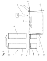
- FIG. 1 shows a schematic view of an inventive stitching machine
- FIG. 2 shows another view of the stitching machine according to FIG. 1 ;
- FIG. 3 shows a schematic view of a variant of the stitching machine
- FIG. 4 shows another view of the stitching machine according to FIG. 3 ;
- FIG. 5 shows a diagram, similar to that of FIGS. 2 and 4 , of another exemplary embodiment of a stitching machine
- FIG. 6 a shows a schematic cross section of a stitching machine in illustration of the movements of the stitcher head and the bending device
- FIG. 6 b shows a schematic diagram of the first position of the bending device during the introduction of a printed product
- FIG. 6 c shows a schematic diagram of the second position of the bending device during the introduction of a printed product
- FIG. 7 shows a schematic diagram of the introduction of a printed product into a stitching machine with two stitcher heads and two bending devices.
- FIG. 8 shows a schematic diagram of the stitching of the printed product which has been introduced into the stitching machine according to FIG. 7 .
- FIGS. 1 and 2 show a stitching machine 1 , which is arranged on a saddle chain 2 of a saddle stitcher 3 known in and of itself.
- the saddle chain 2 has guide plates 4 , which are designed in the form of saddles and on which the printed products 6 can be transported by pusher dogs 5 ( FIGS. 7 and 8 ). Each of the printed products has a fold 6 a .
- the guide plates 4 are designed so that a gap 7 is present between them, which extends in the longitudinal direction of the saddle chain 2 .
- the printed products 6 to be stitched consist of individual printed sheets (not shown here) which have been assembled upstream of the stitching machine 1 on passage through an assembly section (not shown) of the saddle chain 2 .
- the thickness of the printed product 6 at its fold 6 a can be considerably greater than 10 mm, for example.
- the thickness of the printed product 6 at its fold 6 a is reduced to, for example, only 9.5 mm, and the total thickness of the printed product 6 is therefore 19 mm.
- the stitching machine 1 has a stitching slide 8 with a stitching slide upper part 9 and a stitching slide lower part 10 . So that the stitching slide 8 can travel along with each one of the printed products 6 being conveyed on the saddle chain 2 , it is supported on an upper guide 11 and a lower guide 12 , along which it is free to move.
- the upper guide 11 is designed here, for example, as a stationary guide rod, on which the upper part 9 of the stitching slide is supported.
- the sliding movement is accomplished here in the known manner by means of a drive 14 .
- the lower part 10 of the stitching slide is supported on the upper part 9 in such a way that the latter can move transversely to a product travel direction 13 ( FIGS. 7 and 8 ), that is, vertically downward and vertically upward.
- two cylinders 15 are provided, which are operated by the drive 14 of the stitching machine 1 , forming the main drive, and which are connected at the top end to the upper part 9 of the stitching slide and at the bottom end to the lower part 10 of the stitching slide.
- the cylinders 15 are designed as pneumatic actuating cylinders, for example, and are controlled by a machine control unit 16 .
- the vertical movements of the lower part 10 of the stitching slide are limited by stops (not shown here). These stops can be adjustable. The corresponding stroke is therefore preferably adjustable.
- the lower guide 12 is designed so that it allows the previously mentioned vertical movements.
- a separate drive 17 ( FIG. 4 ), such as a servo motor, which is in working connection with the machine control unit 16 , and which is advantageously settable to a predetermined pressing force.
- At least one bending device 18 is connected to the lower part 10 of the stitching slide. This bending device moves jointly with the lower part 10 .
- a stitcher head 19 is arranged, which is attached to the upper part 9 of the stitching slide and moves along with it.
- a wire stitch 20 ( FIG. 8 ) is formed from wire and driven from above through the printed product 6 in the area of the fold 6 a by the stitcher head 19 and then closed on the underside of the product by active or passive bending elements (not shown) of the bending device 18 .
- the bending device 18 has an upper end 18 a , which is located preferably somewhat below the gap 7 between the guide plates 4 , but it can also project into the area of the gap 7 .
- the stitcher head 19 and the bending device 18 can also be offset from each other differently in the direction transverse to the product travel direction 13 .
- the stitcher head 19 can, for example, be arranged underneath the bending device 18 .
- FIGS. 3 and 4 show a stitching machine 1 ′, which differs from the stitching machine 1 described above in that the vertical movements of the lower part 10 of the stitching slide, i.e., of the bending device 18 connected to it, are brought about by a wedge bar 21 , on which the lower part 10 of the stitching slide rests by two rollers 22 spaced a certain distance apart.
- Each end of the wedge bar 21 has a control cam 23 , which rests on a correspondingly designed wedge surface 24 of a spindle nut 25 , which can be shifted horizontally by a spindle 26 .
- the spindle 26 is operated by the separate drive 17 , designed, for example, as a servo motor, which is advantageously mounted directly on the spindle 26 .
- the stitcher head 19 would be mounted on the lower part 10 of the stitching slide, and the cylinders 15 , the wedge bar 21 , or the control cam 28 would be arranged on the upper part 9 of the stitching slide.
- the previously mentioned vertical movements of the lower part 10 of the stitching slide are movements which are executed in addition to, and in synchrony with, the associated stitching operation, that is, with the formation, driving-in, and closing of a wire stitch 20 . This is explained in greater detail below on the basis of FIGS. 6 a - 6 c , 7 , and 8 .
- FIG. 6 a shows a schematic diagram of the stitching machine 1 with a bulky printed product 6 , which has been introduced by the saddle chain 2 and onto which the stitcher head 19 has been lowered in a vertical direction 29 transversely to the product travel direction 13 .
- the bending device 18 has also been brought up from underneath in the vertical direction 30 , thus compressing the printed product 6 .
- the bending device 18 is thus positioned in correspondence with the thickness of the printed products 6 to be stitched, that is, with the thickness of the already precompressed printed products.
- the top end 18 a of the device projects beyond an upper edge 2 a of the saddle chain 2 . It is also in this first position of the bending device 18 , with the stitcher head 19 in the lowered position, that the printed product 6 will be stitched at a later point.
- FIG. 6 b shows the introduction of a thick, that is, bulky, printed product 6 into the stitching machine 1 .
- the stitcher head 19 is located in an upper position, and the bending device 18 is in its first position, which has already been preset in correspondence with the thickness of the printed products 6 to be stitched, the top end 18 a projecting beyond the upper edge 2 a of the saddle chain 2 .
- the thickness of the printed product 6 to be stitched is determined before it is introduced; the value thus found is compared with a predetermined limit value; and, if this limit value is exceeded, the bending device 18 is brought into a predetermined second position, this second position being farther away than the first position from the stitcher head 19 in the direction transverse to the product travel direction 13 , as shown in FIG. 6 c .
- the top end 18 a of the bending device 18 does not project here beyond the upper edge 2 a of the saddle chain 2 .
- the bending device 18 does not interfere with the gap A between the saddle chain 2 and the stitcher head 19 , this being the gap which is available for the introduction of the printed product 6 to be stitched; that is, the space available for the introduction of the printed product 6 to be stitched is greater than that of the known solutions of the prior art.
- the limit value to be applied is predetermined by the machine operator in correspondence with the current processing order; it can depend, for example, on the safety distance between the printed products and the stitcher head required in the individual case and on the production speed.
- a thickness-measuring device 31 designed as a sensor aimed at the saddle chain 2 , is arranged upstream, in the product travel direction 13 , of the stitcher head 19 and of the bending device 18 ( FIG. 7 ).
- the thickness of the printed product 6 can also be determined by some other means, such as by counting in advance the number of printed sheets forming the printed product 6 and by multiplying the known thickness of a printed sheet by this number.
- a thickness-measuring device 31 can also be arranged downstream, in the product travel direction 13 , from the stitcher head 19 and the bending device 18 , wherein the determined thickness can be used in this case only to set the bending device 18 for the printed products 6 following along afterwards.
- FIG. 6 a shows the first position of the bending device 18 , in which the stitching of the printed product 6 also takes place.
- the bending device 18 here is already in its first, preset position for the stitching of the printed product 6 or has been brought into the first position in the vertical direction 30 from the second, lowered position. Only after that is the stitcher head 19 lowered in the vertical direction 29 , resulting in the fixation and compression of the printed product 6 in the area of its fold 6 a . After that, the stitcher head 19 drives the wire stitch 20 into the printed product 6 .
- FIG. 7 shows the product travel direction 13 , in which the printed product 6 is conveyed into a stitching machine 1 equipped with two stitcher heads 19 and two bending devices 18 .
- the stitching slide 8 carrying the stitcher heads 19 and the bending devices 18 is simultaneously moved in a first horizontal direction 32 toward the right, opposite the product travel direction 13 .
- the stitcher heads 19 are located in their upper position, and the two bending devices 18 are in their second, lowered position.
- the space available for the introduction of a printed product 6 between the saddle chain 2 and the stitcher heads 19 is thus larger than that according to the previous solutions of the prior art.
- the machine control unit 16 finds that the predetermined limit value is not exceeded, the bending devices 18 are not lowered into their second position; that is, they remain in their first, elevated position.
- FIG. 8 shows a printed product 6 after it has been introduced into the stitching machine 1 .
- the two bending devices 18 are located in their first, elevated position, in which the printed product 6 is being securely held.
- the two stitcher heads 19 which are in their lowered position, work together with the two bending devices 18 .
- the stitching slide 8 equipped with the stitcher heads 19 and the bending devices 18 , is moved in a second horizontal direction 33 , corresponding to the product travel direction 13 , at the same speed as the printed product 6 .
- the printed product 6 can thus be stitched by the concomitantly traveling stitching slide 8 .
- the stitching device of this exemplary embodiment comprises two bending devices 18 and two stitcher heads 19 , stitching can be conducted with two wire stitches 20 simultaneously. It is obvious that it is also possible to use stitching machines 1 with only one bending device 18 and one stitcher head 19 or a machine with more than two bending devices 18 and stitcher heads 19 .
- the bending devices 18 remain at least initially in their first position, and the stitcher heads 19 are moved upward into the position shown in FIG. 7 , as a result of which the stitched printed product 6 is released again and conveyed away by the saddle chain 2 .
- the stitching slide 8 travels toward the right in its first horizontal direction 32 according to FIG. 7 so that it can accept the following printed product 6 from the saddle chain 2 .
- the stroke which the bending devices 18 execute during the movements cited above can differ for each type of printed product 6 . This stroke is, for example, approximately 8 mm. The stroke is preferably in the range of 5-10 mm.
Landscapes
- Engineering & Computer Science (AREA)
- Textile Engineering (AREA)
- Folding Of Thin Sheet-Like Materials, Special Discharging Devices, And Others (AREA)
- Feeding Of Articles By Means Other Than Belts Or Rollers (AREA)
Applications Claiming Priority (3)
| Application Number | Priority Date | Filing Date | Title |
|---|---|---|---|
| CH1972010 | 2010-02-18 | ||
| CH0197/10 | 2010-02-18 | ||
| CH00197/10 | 2010-02-18 |
Publications (2)
| Publication Number | Publication Date |
|---|---|
| US20110198795A1 US20110198795A1 (en) | 2011-08-18 |
| US8424860B2 true US8424860B2 (en) | 2013-04-23 |
Family
ID=42062530
Family Applications (1)
| Application Number | Title | Priority Date | Filing Date |
|---|---|---|---|
| US13/029,927 Expired - Fee Related US8424860B2 (en) | 2010-02-18 | 2011-02-17 | Stitcher for variable thickness products |
Country Status (4)
| Country | Link |
|---|---|
| US (1) | US8424860B2 (fr) |
| EP (1) | EP2361785B1 (fr) |
| JP (1) | JP5759743B2 (fr) |
| CN (1) | CN102166902B (fr) |
Families Citing this family (6)
| Publication number | Priority date | Publication date | Assignee | Title |
|---|---|---|---|---|
| JP2013184254A (ja) * | 2012-03-08 | 2013-09-19 | Osako Seisakusho:Kk | 中綴製本用ステッチャー装置 |
| DE102014006250A1 (de) * | 2014-04-28 | 2015-10-29 | Müller Martini Holding AG | Hefteinrichtung zum in Bewegung Heften einer Falzbogenanordnung und Verfahren dazu |
| JP6394266B2 (ja) * | 2014-10-15 | 2018-09-26 | コニカミノルタ株式会社 | 用紙処理装置及び画像形成システム |
| JP6582525B2 (ja) * | 2015-05-07 | 2019-10-02 | コニカミノルタ株式会社 | 後処理装置、画像形成システム及び後処理方法 |
| EP3599103B1 (fr) * | 2018-07-25 | 2020-10-14 | Müller Martini Holding AG | Assembleuse et brocheuse pour produits imprimés |
| EP3599104A1 (fr) * | 2018-07-25 | 2020-01-29 | Müller Martini Holding AG | Installation de transport de produits imprimés d'une épaisseur similaire ou différente et leur procédé de transfert vers une réception |
Citations (9)
| Publication number | Priority date | Publication date | Assignee | Title |
|---|---|---|---|---|
| US3899165A (en) | 1972-10-02 | 1975-08-12 | Donnelley & Sons Co | Signature collating and binding system |
| EP0958942A1 (fr) | 1998-05-18 | 1999-11-24 | Grapha-Holding Ag | Agrafeuse pour une brocheuse assembleuse avec chaine collectrice |
| EP1419898A1 (fr) | 2002-11-18 | 2004-05-19 | Müller Martini Holding AG | Dispositif d'agrafage pour la fabrication de produits imprimés à partir d'articles imprimés liees par agrafage |
| EP1629992A1 (fr) | 2004-08-24 | 2006-03-01 | Müller Martini Holding AG | Procédé d'agrafage de produits imprimés et machine d'agrafage |
| US20070069443A1 (en) * | 2005-09-28 | 2007-03-29 | Heidelberger Druckmaschinen Ag | Stitching apparatus and gathering and stitching machine having the stitching apparatus |
| US20090160115A1 (en) * | 2007-12-19 | 2009-06-25 | Kabushiki Kaisha Toshiba | Image forming apparatus, sheet finisher, and method for driving stacking tray |
| US7775509B2 (en) * | 2005-09-14 | 2010-08-17 | Mueller Martini Holdings Ag | Method and arrangement for producing digitally printed newspapers |
| US7780157B2 (en) * | 2007-10-01 | 2010-08-24 | Heidelberger Druckmaschinen Ag | Stitching device and saddle stitcher having the stitching device |
| US20120139177A1 (en) * | 2009-08-05 | 2012-06-07 | Goss International Americas, Inc. | Spring Loaded Corrugated Stitcher Head and Method of Stitching |
Family Cites Families (7)
| Publication number | Priority date | Publication date | Assignee | Title |
|---|---|---|---|---|
| JPH0435994A (ja) * | 1990-05-31 | 1992-02-06 | Toshiba Corp | 紙葉類綴込み装置および紙葉類綴込み装置を有する画像形成装置 |
| JPH04119896A (ja) * | 1990-09-11 | 1992-04-21 | Canon Inc | シート綴じ装置及びシート綴じ装置を有するシート後処理装置 |
| JP3713393B2 (ja) * | 1998-10-27 | 2005-11-09 | 株式会社リコー | 用紙処理装置 |
| JP4124069B2 (ja) * | 2003-09-12 | 2008-07-23 | コニカミノルタビジネステクノロジーズ株式会社 | 用紙処理装置および画像形成装置 |
| DE102004021958A1 (de) * | 2004-05-04 | 2005-12-01 | Heidelberger Druckmaschinen Ag | Sammelhefter für Broschuren |
| JP4719637B2 (ja) * | 2005-08-11 | 2011-07-06 | キヤノン株式会社 | シート処理装置及び画像形成装置 |
| JP5310381B2 (ja) * | 2009-08-24 | 2013-10-09 | マックス株式会社 | 上下分離型電動ステープラ |
-
2011
- 2011-02-08 EP EP11153648.8A patent/EP2361785B1/fr not_active Not-in-force
- 2011-02-17 US US13/029,927 patent/US8424860B2/en not_active Expired - Fee Related
- 2011-02-18 JP JP2011034032A patent/JP5759743B2/ja not_active Expired - Fee Related
- 2011-02-18 CN CN201110041767.5A patent/CN102166902B/zh not_active Expired - Fee Related
Patent Citations (15)
| Publication number | Priority date | Publication date | Assignee | Title |
|---|---|---|---|---|
| US3899165A (en) | 1972-10-02 | 1975-08-12 | Donnelley & Sons Co | Signature collating and binding system |
| EP0958942A1 (fr) | 1998-05-18 | 1999-11-24 | Grapha-Holding Ag | Agrafeuse pour une brocheuse assembleuse avec chaine collectrice |
| US6142353A (en) * | 1998-05-18 | 2000-11-07 | Graph-Holding Ag | Stapling arrangement for a gathering and stapling machine having a gathering chain |
| EP1419898A1 (fr) | 2002-11-18 | 2004-05-19 | Müller Martini Holding AG | Dispositif d'agrafage pour la fabrication de produits imprimés à partir d'articles imprimés liees par agrafage |
| US20040094883A1 (en) * | 2002-11-18 | 2004-05-20 | Muller Martini Holding Ag | Wire-stitching apparatus for producing wire stitched print items |
| US7032898B2 (en) * | 2002-11-18 | 2006-04-25 | Muller Martini Holding Ag | Wire-stitching apparatus for producing wire stitched print items |
| US20060043663A1 (en) * | 2004-08-24 | 2006-03-02 | Muller Martini Holding Ag | Method for stitching print products and stitching machine for realizing said method |
| EP1629992A1 (fr) | 2004-08-24 | 2006-03-01 | Müller Martini Holding AG | Procédé d'agrafage de produits imprimés et machine d'agrafage |
| US7775509B2 (en) * | 2005-09-14 | 2010-08-17 | Mueller Martini Holdings Ag | Method and arrangement for producing digitally printed newspapers |
| US20070069443A1 (en) * | 2005-09-28 | 2007-03-29 | Heidelberger Druckmaschinen Ag | Stitching apparatus and gathering and stitching machine having the stitching apparatus |
| US7637489B2 (en) * | 2005-09-28 | 2009-12-29 | Heidelberger Druckmaschinen Ag | Stitching apparatus and gathering and stitching machine having the stitching apparatus |
| EP1769937A1 (fr) | 2005-09-29 | 2007-04-04 | Heidelberger Druckmaschinen Aktiengesellschaft | Agrafeuse avec tête réglable en hauteur |
| US7780157B2 (en) * | 2007-10-01 | 2010-08-24 | Heidelberger Druckmaschinen Ag | Stitching device and saddle stitcher having the stitching device |
| US20090160115A1 (en) * | 2007-12-19 | 2009-06-25 | Kabushiki Kaisha Toshiba | Image forming apparatus, sheet finisher, and method for driving stacking tray |
| US20120139177A1 (en) * | 2009-08-05 | 2012-06-07 | Goss International Americas, Inc. | Spring Loaded Corrugated Stitcher Head and Method of Stitching |
Also Published As
| Publication number | Publication date |
|---|---|
| CN102166902A (zh) | 2011-08-31 |
| CN102166902B (zh) | 2015-06-17 |
| JP2011168051A (ja) | 2011-09-01 |
| EP2361785B1 (fr) | 2015-11-11 |
| EP2361785A1 (fr) | 2011-08-31 |
| JP5759743B2 (ja) | 2015-08-05 |
| US20110198795A1 (en) | 2011-08-18 |
Similar Documents
| Publication | Publication Date | Title |
|---|---|---|
| US20110198795A1 (en) | Method for stitching printed products with a stitching machine and a stitching machine for implementing the method | |
| US7621708B2 (en) | Apparatus and method for pressing a cover onto a moving printing material block | |
| EP2392530B1 (fr) | Plieuse de feuilles | |
| US20090155022A1 (en) | Device for feeding book blocks | |
| EP3023240B1 (fr) | Machine de fabrication de boîte avec un dispositif d'équerrage dans un éjecteur à compteur | |
| CN106005539A (zh) | 一种医用手套内衬纸包装折纸机 | |
| JP3642413B2 (ja) | 空気圧式矯正フィンガーを備える矯正キャリッジ | |
| EP1419898B1 (fr) | Dispositif d'agrafage pour la fabrication de produits imprimés à partir d'articles imprimés liees par agrafage | |
| US8376346B2 (en) | Device and method for producing stacks composed of printed sheets | |
| ITMI20011482A1 (it) | Procedimento e dispositivi per la cucitura a macchina di prodotti di tipografia in piu' pezzi per mezzo di graffe di filo metallico | |
| US1608838A (en) | Book-stitching machine | |
| US6607070B2 (en) | Method and device for transferring book blocks into a transport device belonging to a bookbinding machine | |
| EP2020305B1 (fr) | Dispositif et procédé destiné à la pression d'une enveloppe ou d'un renfort sur un dos encollé | |
| CN109070379A (zh) | 排出器构件和板材式元件加工机 | |
| US20090289411A1 (en) | Apparatus for stacking sheet-like products, in particular printed products | |
| US9180720B2 (en) | Method for operating a book forming and pressing machine | |
| US20130154177A1 (en) | Method for controlling a feeder of a gathering-stitching machine | |
| US10974533B2 (en) | Device and method for the alignment of a book block consisting of single sheets and/or signatures | |
| CN209668173U (zh) | 陶瓷制品输送带过渡衔接机构 | |
| US7988138B2 (en) | Gatherer stitcher with variable chain pitch | |
| CN104029515B (zh) | 用于装订的方法和仅使用一个装订头的装订方法 | |
| CN107546406A (zh) | 蓄电池包板机 | |
| US20250001636A1 (en) | Apparatus and method for carrying out cutting operations on format edges of at least one printed product configured with a jaw fold or cover | |
| US5695596A (en) | Apparatus for laying up veneer panels | |
| CN212529092U (zh) | 一种纸制品自动打订装置 |
Legal Events
| Date | Code | Title | Description |
|---|---|---|---|
| AS | Assignment |
Owner name: MULLER MARTINI HOLDING AG, SWITZERLAND Free format text: ASSIGNMENT OF ASSIGNORS INTEREST;ASSIGNORS:FLUCK, ANDREAS;GRABER, DANIEL;DYSLI, LUKAS;SIGNING DATES FROM 20110228 TO 20110301;REEL/FRAME:025969/0200 |
|
| STCF | Information on status: patent grant |
Free format text: PATENTED CASE |
|
| FPAY | Fee payment |
Year of fee payment: 4 |
|
| FEPP | Fee payment procedure |
Free format text: MAINTENANCE FEE REMINDER MAILED (ORIGINAL EVENT CODE: REM.); ENTITY STATUS OF PATENT OWNER: LARGE ENTITY |
|
| LAPS | Lapse for failure to pay maintenance fees |
Free format text: PATENT EXPIRED FOR FAILURE TO PAY MAINTENANCE FEES (ORIGINAL EVENT CODE: EXP.); ENTITY STATUS OF PATENT OWNER: LARGE ENTITY |
|
| STCH | Information on status: patent discontinuation |
Free format text: PATENT EXPIRED DUE TO NONPAYMENT OF MAINTENANCE FEES UNDER 37 CFR 1.362 |
|
| FP | Lapsed due to failure to pay maintenance fee |
Effective date: 20210423 |