US9291300B2 - Rotary actuator driven vibration isolation - Google Patents
Rotary actuator driven vibration isolation Download PDFInfo
- Publication number
- US9291300B2 US9291300B2 US13/843,266 US201313843266A US9291300B2 US 9291300 B2 US9291300 B2 US 9291300B2 US 201313843266 A US201313843266 A US 201313843266A US 9291300 B2 US9291300 B2 US 9291300B2
- Authority
- US
- United States
- Prior art keywords
- vibration isolation
- isolation system
- link
- suspended platform
- base
- Prior art date
- Legal status (The legal status is an assumption and is not a legal conclusion. Google has not performed a legal analysis and makes no representation as to the accuracy of the status listed.)
- Active
Links
Images




Classifications
-
- F—MECHANICAL ENGINEERING; LIGHTING; HEATING; WEAPONS; BLASTING
- F16—ENGINEERING ELEMENTS AND UNITS; GENERAL MEASURES FOR PRODUCING AND MAINTAINING EFFECTIVE FUNCTIONING OF MACHINES OR INSTALLATIONS; THERMAL INSULATION IN GENERAL
- F16M—FRAMES, CASINGS OR BEDS OF ENGINES, MACHINES OR APPARATUS, NOT SPECIFIC TO ENGINES, MACHINES OR APPARATUS PROVIDED FOR ELSEWHERE; STANDS; SUPPORTS
- F16M13/00—Other supports for positioning apparatus or articles; Means for steadying hand-held apparatus or articles
- F16M13/02—Other supports for positioning apparatus or articles; Means for steadying hand-held apparatus or articles for supporting on, or attaching to, an object, e.g. tree, gate, window-frame, cycle
-
- B—PERFORMING OPERATIONS; TRANSPORTING
- B60—VEHICLES IN GENERAL
- B60N—SEATS SPECIALLY ADAPTED FOR VEHICLES; VEHICLE PASSENGER ACCOMMODATION NOT OTHERWISE PROVIDED FOR
- B60N2/00—Seats specially adapted for vehicles; Arrangement or mounting of seats in vehicles
- B60N2/50—Seat suspension devices
- B60N2/501—Seat suspension devices actively controlled suspension, e.g. electronic control
-
- B—PERFORMING OPERATIONS; TRANSPORTING
- B60—VEHICLES IN GENERAL
- B60N—SEATS SPECIALLY ADAPTED FOR VEHICLES; VEHICLE PASSENGER ACCOMMODATION NOT OTHERWISE PROVIDED FOR
- B60N2/00—Seats specially adapted for vehicles; Arrangement or mounting of seats in vehicles
- B60N2/50—Seat suspension devices
- B60N2/502—Seat suspension devices attached to the base of the seat
-
- B—PERFORMING OPERATIONS; TRANSPORTING
- B60—VEHICLES IN GENERAL
- B60N—SEATS SPECIALLY ADAPTED FOR VEHICLES; VEHICLE PASSENGER ACCOMMODATION NOT OTHERWISE PROVIDED FOR
- B60N2/00—Seats specially adapted for vehicles; Arrangement or mounting of seats in vehicles
- B60N2/50—Seat suspension devices
- B60N2/506—Seat guided by rods
-
- B—PERFORMING OPERATIONS; TRANSPORTING
- B60—VEHICLES IN GENERAL
- B60N—SEATS SPECIALLY ADAPTED FOR VEHICLES; VEHICLE PASSENGER ACCOMMODATION NOT OTHERWISE PROVIDED FOR
- B60N2/00—Seats specially adapted for vehicles; Arrangement or mounting of seats in vehicles
- B60N2/50—Seat suspension devices
- B60N2/506—Seat guided by rods
- B60N2/508—Scissors-like structure
-
- B—PERFORMING OPERATIONS; TRANSPORTING
- B60—VEHICLES IN GENERAL
- B60N—SEATS SPECIALLY ADAPTED FOR VEHICLES; VEHICLE PASSENGER ACCOMMODATION NOT OTHERWISE PROVIDED FOR
- B60N2/00—Seats specially adapted for vehicles; Arrangement or mounting of seats in vehicles
- B60N2/50—Seat suspension devices
- B60N2/52—Seat suspension devices using fluid means
- B60N2/525—Seat suspension devices using fluid means using gas
-
- F—MECHANICAL ENGINEERING; LIGHTING; HEATING; WEAPONS; BLASTING
- F16—ENGINEERING ELEMENTS AND UNITS; GENERAL MEASURES FOR PRODUCING AND MAINTAINING EFFECTIVE FUNCTIONING OF MACHINES OR INSTALLATIONS; THERMAL INSULATION IN GENERAL
- F16F—SPRINGS; SHOCK-ABSORBERS; MEANS FOR DAMPING VIBRATION
- F16F15/00—Suppression of vibrations in systems; Means or arrangements for avoiding or reducing out-of-balance forces, e.g. due to motion
- F16F15/02—Suppression of vibrations of non-rotating, e.g. reciprocating systems; Suppression of vibrations of rotating systems by use of members not moving with the rotating systems
Definitions
- Vibration isolation systems attempt to isolate a payload from a vibration disturbance. Vibration isolation systems may be passive, semi active, or fully active. A fully active vibration isolation system employs a source capable of exerting a force of arbitrary magnitude and phase, absent any disturbance, as part of the isolation system.
- Some applications for vibration isolations systems are ground vehicles, watercraft or air craft. Vehicles such as passenger cars, long haul trucks, construction equipment and the like typically employ some type of suspension system as a vibration isolation system in order to isolate the vehicle occupant(s) from vibration induced by disturbances encountered by the vehicle as it travels along a path (where the path may be on and/or off road). In some vehicles, however, the vehicle suspension may not be adequate to effectively isolate vehicle occupant(s) from the road induced disturbances.
- Vehicles such as these may have a “harsher” suspension than a passenger vehicle and which drivers may occupy for long periods of time.
- Vehicles such as these may have a second suspension, to control relative motion between the occupant's seat and the vehicle cabin.
- the seat suspension may be passive, semi-active, or may be fully active.
- a vibration isolation system has a suspended platform, a base and an exoskeleton, where the exoskeleton includes a first scissors mechanism comprising first and second main links of unequal length and first and second secondary links where the first and second main links are pivotably coupled to each other at an intermediate point, a second scissors mechanism comprising third and fourth main links of unequal length and third and fourth secondary links where the third and fourth main links are pivotably coupled to each other at an intermediate point, wherein the first and second scissors mechanism support the suspended platform relative to the base over an intended range of travel, wherein the first and second main links pass through parallel as the vibration isolation system is displaced over the intended range of travel and the third and fourth main links pass through parallel as the vibration isolation system is displaced over the intended range of travel.
- Embodiments may include one or more of the following features.
- the first, second, third and fourth secondary links are oriented in the same direction.
- the first, second, third and fourth secondary links are parallel to each other.
- the first, second, third, and fourth secondary links are of equal length.
- a rotary actuator for outputting a force to displace the suspended platform relative to the base over a range of travel the rotary actuator comprising first and second rotors, wherein the rotary actuator is free to translate relative to the suspended platform and the vibration isolation system base.
- the relative rotation of the first and second rotors with respect to each other is less than one full revolution, for displacement of the suspended platform relative to the base over the entire range of travel.
- a rotary actuator comprising first and second rotors wherein the relative rotation of the first and second rotors with respect to each other is less than one full revolution for the full range of travel of the suspended platform relative to the base, and a drive mechanism separate from the exoskeleton for applying output force from the rotary actuator to at least one of the suspended platform and the base.
- a rotary actuator comprising first and second rotors wherein both the first and second rotors are free to rotate relative to the exoskeleton, wherein the rotary actuator is inertially coupled to one of the suspended platform and the base, and a drive mechanism, separate from the exoskeleton, for coupling output force from both the first and second rotors of the rotary actuator to the one of the suspended platform and the base to which the rotary actuator is not inertially coupled.
- a rotary actuator comprising first and second rotors wherein both the first and second rotors are free to rotate relative to the exoskeleton wherein the rotary actuator is free to translate relative to the suspended platform and the vibration isolation system base.
- FIG. 1 is a schematic view of a vehicle with a passive vehicle suspension and an active vibration isolation seat system.
- FIG. 2 a is a schematic view of one embodiment of an active vibration isolation system.
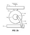
- FIG. 2 b is a schematic view of one embodiment of another active vibration isolation system.
- FIG. 2 c is a schematic view of one embodiment of another active vibration isolation system.
- FIG. 2 d is a schematic view of one embodiment of another active vibration isolation system.
- FIG. 2 e is a schematic view of one embodiment of another active vibration isolation system.
- FIG. 2 f is a schematic view of one embodiment of another active vibration isolation system.
- FIG. 3 a is a schematic view of one embodiment of another active vibration isolation system.
- FIG. 3 b is a schematic view of one embodiment of another active vibration isolation system.
- FIG. 4 a is a perspective view of a scissors exoskeleton mechanism with some portions of the exoskeleton frame omitted.
- FIG. 4 b is a perspective view of a scissors exoskeleton mechanism that includes the omitted portions of the exoskeleton frame of FIG. 4 a.
- FIG. 5 a is perspective view of a scissors exoskeleton in collapsed position.
- FIG. 5 b is perspective view of a scissors exoskeleton in extended position.
- FIG. 6 is a perspective view of a doubly acting flying actuator showing the actuator, drive links, central shaft, and pneumatic springs.
- FIG. 7 is a (rotated) perspective view of the system of FIG. 6 incorporated into the exoskeleton assembly of FIG. 5 b.
- FIG. 8 is a cutaway view of one end of a drive link.
- FIG. 9 a is a perspective view of select portions of a vibration isolation system showing an embodiment having a spring support and link arrangement for preload of drive links.
- FIG. 9 b is another perspective view of select portions of a vibration isolation system of FIG. 9 a showing the orientation of the system drive links.
- FIG. 10 is a perspective view of an embodiment of an active vibration isolation system using cams and cam followers as the direct drive mechanism.
- the present disclosure is directed to active vibration isolation systems.
- the active vibration isolation systems will be described in terms of providing isolation to a plant (which will encompass a suspended platform on which a payload resides, but may encompass other elements also) from a vibration input applied to a base which the vibration isolation system is coupled.
- the active vibration system applies controlled forces between the base and suspended platform in order to provide vibration isolation to the suspended platform on which the payload resides.
- Many of the embodiments disclosed herein will discuss active vibration systems as applied to a vehicle seat. However, it should be understood that the vibration isolation systems described are not limited to application in a vehicle seat. Any application in which it is desired to isolate a payload from some vibration input is contemplated herein.
- the isolated plant encompasses the entire structure that is isolated from the input vibration.
- the seat top frame, cushions, armrests, etc. are all part of the suspended plant.
- an occupant of the actively suspended seat will also become part of the plant (since it is the occupant we are most interested in isolating, in this example the occupant would be the payload).
- the embodiments to be further described are related to the arrangements of components of the active suspension system which are located between the structure that is vibrating and the payload which it is desired to isolate from the vibration.
- suspension 12 is an active seat suspension including a force source 20 , a sensor 22 , and a controller 24 . Some active suspensions may have multiple sensors, and possibly even multiple force sources.
- the suspension 12 may also have a spring 26 to support the static weight of the seat 28 .
- Spring 26 may be a variable spring with a controllable spring constant or be a spring with provision to apply a controllable pre-load.
- the force source 20 is inertially coupled to the vehicle floor 25 .
- vehicle wheel 15 traverses disturbances as it traverses path 16 .
- the disturbances along the path cause forces to be applied to the vehicle wheel, which are in turn communicated to the vehicle floor 25 through vehicle suspension spring 18 and damper 19 .
- the vehicle body which rests upon vehicle suspension elements 18 and 19 (note that only one wheel of a vehicle is shown) is typically referred to as the sprung mass, and the mass of the wheel assembly is typically referred to as the unsprung mass.
- Motion of the unsprung mass imparts forces into the suspension elements which in turn imparts forces into the sprung mass.
- Seat suspension 12 is used to isolate seat 28 from motion of the sprung vehicle mass.
- Sensor 22 detects a quantity related to vertical motion of the seat 28 (such as vertical acceleration, vertical displacement, or vertical velocity).
- the output of sensor 22 (and other sensors if present) is/are provided as input data to the controller 24 .
- the controller 24 determines what output force should be exerted by the force source 20 in order to control motion of the seat 28 , and controller 24 issues commands that cause force source 20 to exert the needed force.
- An active, closed loop vibration control system suitable for use as seat suspension 12 is described in detail in U.S. Pat. No. 7,983,813, “Active Suspending”, to Umethala et al., which is herein incorporated by reference in its entirety.
- the force source disclosed was a linear actuator with a moving magnet armature.
- a linear actuator may not be the optimal choice.
- a rotary actuator may be a better choice.
- portions of the linear actuator armature that extend outside of the stator envelope do not contribute significantly to the force output of the actuator.
- Embodiments described herein benefit from particular arrangements of the elements of the vibration control system, as will be described in more detail.
- Embodiments disclosed herein employ a rotary actuator.
- Use of conventional transmission mechanisms such as ball nuts and ball screws, planetary gear heads, etc. has been avoided.
- Such conventional transmissions can provide the useful benefit of allowing the size of a motor for a particular application to be reduced by introducing a motion ratio where multiple revolutions of the motor are translated into a different number of revolutions of the transmission output (generally more revolutions of the motor are transformed into fewer rotations of the transmission output to provide a force amplification factor allowing the motor size to be reduced for a desired output force).
- a motion sensor near the point at which the force is applied to the controlled element (i.e. the suspended platform which is part of the suspended plant).
- the presence of a transmission separates the point of application of the force output of the force source from the suspended platform to be controlled (the transmission is disposed between the force source and the suspended platform portion of the plant).
- Any irregularities in the transmission such as backlash, slippage, friction, stiction and the like, may introduce the possibility of instabilities in the control loop.
- it is very difficult to avoid lash, noise, and wear in a transmission mechanism especially over long periods of operation as components wear, lubrication degrades, etc. By avoiding the use of a conventional transmission mechanism within the closed control loop, these difficulties are avoided.
- the direct drive mechanism employs pivoting links to transmit force from the force source to plant (and/or between the force source and the vibration isolation system base).
- the angular displacement of the pivoting link relative to the location on the force source where it couples will be relatively large. Coupling the link to the force source will preferably be accomplished using a rotary bearing that does not constrain relative rotation of the link end relative to its connection location to the force source, but does constrain translation of the link relative to its connection location to the force source.
- the angular displacement of the link end that connects to the suspended plant and/or to the vibration isolation system base sees less angular displacement relative to its respective connection location to the plant (and/or to the mechanical ground) than the first link connection point sees relative to the force source connection location (as described above).
- this connection of the pivoting link to the plant (and/or the vibration isolation system base) is accomplished with a rotary bearing also, as the first connection point to the force source is accomplished.
- the rotary bearing can be replaced by a rotationally compliant elastomeric bushing or a flexure.
- the bushing or flexure should be rotationally compliant to allow the required angular displacement of the link end relative to the plant (and/or the vibration isolation system base) connection point, while substantially constraining translation of the link end relative to its connection point location to the plant (and/or to the vibration isolation system base).
- the direct drive mechanisms described above employ elements to connect the link ends to the force source and to the plant and/or vibration isolation system base as needed that allow the required relative rotation of the link ends to their respective connection points to the force source, plant and/or vibration isolation system base, while constraining translation motion of the link ends relative to their respective connection points.
- Rotary bearings, rotationally compliant bushings, flexures, or any other known mechanism that can accommodate the necessary relative rotation while substantially constraining relative translation motion can be used as part of the direct drive mechanism, and the disclosure herein is not limited to the use of any particular connection mechanism.
- both a drive mechanism and a separate support mechanism are used.
- the drive mechanism is configured such that it directly couples the force output from the rotary actuator to the suspended platform (in the general case, the coupling is from the rotary actuator to the plant.
- the coupling is between the rotary actuator and the frame of the seat top, or to a platform to which the seat top frame is mounted).
- a motion sensor can be located on the suspended platform at or near the location the force output of the force source is coupled to the suspended platform.
- locating a motion sensor at or near the force application point on the plant is advantageous, as the effects of bending modes and other extraneous vibrations of other plant structures can be minimized. Such an arrangement improves stability of the closed loop control system. Additional sensors may be located elsewhere as needed.
- the exoskeleton is configured to resist extraneous forces (other than in the controlled motion degree of freedom), so the drive mechanism is relieved of the need to resist such forces. This simplifies the design of the force source and drive linkage, and increases reliability of the system. Additionally, the control loop is not closed through the exoskeleton (support structure), which enhances isolation system stability.
- a scissors mechanism is one embodiment of an exoskeleton suitable for use with the various embodiments described herein.
- a scissors mechanism can provide rectilinear, or close to rectilinear motion.
- Conventional scissors mechanisms typically use a sliding surface or linear bearing, which can introduce problems such as increased friction, rattling, wear, backlash controllability problems, etc.
- Some useful exoskeleton mechanisms constrain motion to be curvilinear.
- Various pivoting link mechanisms known in the art such as four bar links, may be used. If an exoskeleton that constrains motion to be curvilinear is used, the drive mechanism must also be configured to accommodate motion in one or more other degrees of freedom, in addition to the controlled motion axis degree of freedom.
- the drive mechanism In a 4 bar link exoskeleton no sliding surfaces or linear bearings are needed, which provides a cost and reliability benefit.
- Rotary bearings generally are less expensive, more reliable, and suffer less from lash, stiction, and other non-linearities as compared to linear bearings or sliding surfaces.
- rotary actuators are typically described as having a rotor component and a stator component, where the rotor rotates relative to the stator.
- the stator is fixed relative to a mechanical reference (both inertially and rotationally) and the rotor rotates relative to the fixed stator.
- this is a somewhat arbitrary and limiting description of rotary actuators.
- inner and outer rotors For purposes of this disclosure, rather than specifically identifying a rotor and stator, we will describe inner and outer rotors.
- the rotary actuator allows there to be relative rotation between the inner and outer rotors.
- Various embodiments will be described that couple one or both of the inner and outer rotors in various manners to various portions of the vibration isolation system.
- one of the rotors may be rotationally fixed relative to a mechanical ground reference (such as the vibration isolation system base or the suspended platform). In some embodiments, both rotors will be free to rotate relative to the mechanical ground reference. In some embodiments, the relative rotation of the inner rotor with respect to the outer rotor of the rotary actuator is limited to be less than one complete revolution, for the entire range of travel of the suspended platform relative to the vibration isolation system base. In some embodiments the relative rotation of the inner rotor with respect to the mechanical ground reference and the relative rotation of the outer rotor with respect to the mechanical ground reference are each limited to be less than one complete revolution, for the entire range of travel of the suspended platform relative to the vibration isolation system base.
- Rotary actuators can be DC rotating machines or AC rotating machines. They may use permanent magnets or may be induction or switched reluctance machines that do not rely on permanent magnets. Rotary actuators may use rare earth permanent magnets such as NdFeB, or may use less expensive ceramic magnets, or no magnets. Rotary actuators may be hydraulic or pneumatic. The embodiments disclosed herein are not limited in any way as regards the physical principles employed to create relative motion between the inner and outer rotors, and any known rotary actuator may be used.
- FIGS. 2 a - 2 f , and 3 a - 3 c schematically show various embodiments of an active vibration isolation system using a rotary actuator. These figures describe arrangement of the rotary actuator, direct drive mechanism, vibration isolation system base and suspended platform (plant). The exoskeleton and details of the control system have been omitted for clarity.
- the rotary actuator 100 is inertially fixed to a mechanical ground reference.
- the mechanical ground reference refers to a selected arbitrary mechanical reference point.
- the mechanical ground reference can be selected to be virtually any point within the system (or even a point external to the system such as the earth).
- the mechanical ground reference will typically be chosen to be either the vibration isolation system base or the suspended platform.
- the mechanical ground reference is chosen to be the vibration isolation system base 101 .
- the mechanical ground reference is chosen to be the suspended platform 102 .
- inertially fixed to the mechanical ground
- the rotary actuator 100 moves with the base 101 .
- the rotary actuator 100 moves with the suspended platform 102 and the mass of rotary actuator 100 becomes part of the moving mass of the suspended platform 102 .
- the rotary actuator 100 is inertially coupled to some part of the active suspension system other than the base 101 or the suspended platform 102 . In this configuration, the rotary actuator 100 translates with respect to both the base 101 and the suspended platform 102 .
- This configuration we refer to this configuration as a flying actuator. These configurations are shown in FIGS. 3 a - 3 b , and will be described in more detail below.
- one of the inner rotor and outer rotor of the rotary actuator is fixed rotationally relative to a mechanical ground reference, and the other of the inner rotor and outer rotor can rotate relative to the mechanical ground.
- outer rotor 103 of the rotary actuator 100 is rotationally fixed (as well as inertially fixed) with respect to the mechanical ground (base 101 ).
- the inner rotor 104 can rotate relative to the mechanical ground, and relative to the suspended platform 102 .
- a direct drive mechanism 105 couples the inner rotor 104 to the suspended platform 102 .
- the direct drive mechanism shown is a pivoting link mechanism, where rigid link 106 is coupled to the inner rotor 104 through rotary bearing 110 and is also coupled to the suspended platform 102 via a second rotary bearing 111 .
- Other direct drive mechanisms such as a cam and cam follower, may also be used here in place of the rotary link direct drive mechanism
- the rotary actuator is inertially fixed to the suspended platform 102 .
- the outer rotor 103 is rotationally fixed relative to the suspended platform 102 , which in this embodiment has been chosen to be the mechanical ground reference.
- the inner rotor 104 can rotate relative to the mechanical ground, and relative to the base 101 .
- a direct drive mechanism 105 couples the inner rotor 104 to the base 101 .
- Direct drive mechanism 105 incorporates rigid link 106 which is coupled to the inner rotor 104 through rotary bearing 110 and is also coupled to the vibration isolation system base 101 through rotary bearing 112 .
- the rotary actuator inner rotor 104 is inertially and rotationally fixed relative to the mechanical ground which is chosen to be the base 101 and the outer rotor 103 is allowed to rotate with respect to the mechanical ground.
- the outer rotor 103 is coupled to the suspended platform 102 via direct drive mechanism 105 .
- Direct drive mechanism 105 incorporates a rigid link 106 .
- the rigid link 106 is coupled to the outer rotor 103 via a first rotary bearing 113 and is coupled to the suspended platform 102 via a second rotary bearing 111 .
- Direct drive mechanism 105 couples the outer rotor 103 to the vibration isolation system base 101 .
- Direct drive mechanism 105 incorporates rigid link 106 , which is rotationally coupled to the outer rotor 103 through rotary bearing 113 and is rotationally coupled to the vibration isolation system base 101 through rotary bearing 112 .
- both the inner rotor 104 and the outer rotor 103 it is possible to allow both the inner rotor 104 and the outer rotor 103 to rotate relative to both the base 101 and the suspended platform 102 .
- the rotary actuator 100 is inertially coupled to the mechanical ground, which in this embodiment is the base 101 .
- Both the inner rotor 104 and outer rotor 103 are free to rotate relative to both the base 101 and the suspended platform 102 .
- neither the inner rotor 104 nor outer rotor 103 are rotationally fixed relative to the mechanical ground.
- Embodiments where both the inner rotor and outer rotor are free to rotate relative to the mechanical ground are referred to herein as doubly acting.
- the inner and outer rotors rotate in opposite directions relative to each other.
- a first rigid link 123 is coupled to the inner rotor 104 through a first rotary bearing 124 and is coupled to the suspended platform 102 via a second rotary bearing 125 .
- a second rigid link 130 is coupled to the outer rotor 103 via a 3 rd rotary bearing 113 and is coupled to the suspended platform 102 via a 4 th rotary bearing 111 .
- a central shaft 140 extending through the rotary actuator is fixed to the inner rotor 104 and is coupled to an actuator mount 150 through a 5 th rotary bearing 141 .
- Actuator mount 150 is fixed to (and therefore also inertially fixed to) the vibration isolation system base, which has been chosen to be the mechanical ground.
- the central shaft extends through the motor and couples to actuator mounts located on either side of the motor.
- the central shaft is fixed to the inner rotor and is rotationally coupled to the actuator mount(s).
- a practical benefit of fixing the central shaft to the inner rotor is that the central shaft can then be used as a mounting point for a crank arm for coupling the direct drive link to the inner rotor, which provides packaging flexibility.
- the central shaft could have been fixed to the actuator mounts and rotationally coupled to the inner rotor through bearings.
- FIG. 2 f shows another embodiment which is substantially similar to the embodiment of FIG. 2 e . It will not be described in detail, other than to mention that the mechanical ground is chosen to be the suspended platform, rather than the base as in FIG. 2 e.
- FIG. 3 b actually depicts a connection of links used in a configuration where the motor is not inertially coupled to either the isolation system base or the suspended platform. This arrangement will be described shortly.
- the same configuration used in FIG. 3 b to alter the effective radius of the inner rotor crank arm is also applicable to other embodiments such as the doubly acting inertially fixed embodiments of FIGS. 2 e and 2 f , as well as the other embodiments shown in this disclosure.)
- the effective inner rotor diameter is made equal to the diameter of the connection of the outer rotor rigid link with respect to the rotation center of the actuator
- a flying actuator embodiment is also possible.
- the rotary actuator need not be inertially coupled to either the vibration isolation system base or the suspended platform.
- the actuator is allowed to translate with respect to both the vibration isolation base and the suspended platform.
- the actuator is constrained in a manner that allows for application of force between the suspended platform and the base in the controlled motion degree of freedom, from the rotary actuator through the direct drive mechanism.
- a doubly acting, flying actuator embodiment is shown in FIGS. 3 a - b and will be described in more detail in a subsequent section.
- FIG. 10 An example direct drive mechanism using a cam and cam follower in a doubly acting flying actuator embodiment is shown in FIG. 10 .
- Cam 1030 is connected to the outer rotor of actuator 1000 and drives cam follower 1050 .
- Cam follower 1050 is connected to the suspended platform (the suspended platform has been omitted in this view to allow the structures underneath to be visible).
- Cam 1031 is fixed to central shaft 1040 which is fixed to the inner rotor of actuator 100 .
- Cam 1031 drives cam follower 1051 , and cam follower 1051 is fixed to the vibration isolation system base.
- Cam 1030 and cam follower 1050 are analogous to pivoting link 330 of FIG.
- cam 1031 and cam follower 1051 are analogous to link 331 and crank arm 341 of FIG. 3 b . It should be noted here that cams and cam followers could be used as direct drive links in other embodiments described herein, and are not limited to use with doubly acting flying actuator embodiments.
- FIGS. 4 a and 4 b depict an exoskeleton for a vibration isolation system using a scissors mechanism requiring only pivoting links. No sliding contacts or linear bearings are required.
- FIGS. 4 a and 4 b provide a perspective view of the scissors exoskeleton support structure 400 , where FIG. 4 a has some portions of the vibration isolation system frame removed to better show elements of the scissors structure.
- Structure 400 has two scissors mechanisms mounted on opposite sides of the vibration isolation system.
- First scissors mechanism 430 includes a pair of main support links 432 and 433 pivotably connected to each other through a centrally mounted bearing 440 forming a first main scissors mechanism on one side of structure 400 .
- a second scissors mechanism 431 is partially visible behind scissors mechanism 430 .
- Second scissors mechanism 431 is identical in structure to scissors mechanism 430 and will not be described further.
- Main link 432 is pivotably connected to isolated platform 402 via bearing 442 .
- Main link 432 is also pivotably connected to secondary link 434 via bearing 435 .
- Main link 433 is pivotably connected to vibration isolation base 401 via bearing 441 .
- Main link 433 is also pivotably connected to secondary link 437 via bearing 438 .
- Secondary link 434 is connected to main link 432 as described earlier, and is also pivotably connected to vibration isolation base 401 via bearing 436 .
- Secondary link 437 is coupled to main link 433 as described earlier, and is also pivotably connected to isolated platform 402 via bearing 439 . It can be seen that scissors mechanism 430 (and also scissors mechanism 431 ) do not use any sliding surfaces or linear bearings. Introduction of the secondary links allows the scissors mechanism to function using only rotary bearings. This is beneficial as rotary bearings can be lower cost and more reliable than linear bearings, and have lower friction and freedom from stiction compared to use of sliding surfaces.
- main links 432 and 433 are of unequal length. Use of unequal length main links in a scissors mechanism allows the main links to pass by each other as the suspended platform 102 moves relative to the vibration isolation system base 401 . That is, the main links can cross over through the point where the main links are parallel to each other. Allowing a scissors mechanism to move through this crossover point improves overall linearity of motion of the scissors exoskeleton. Moving the crossover point to be close to the midpoint of exoskeleton suspension travel further improves linearity.
- both of the added secondary links are oriented in the same direction away from the main link member to which they are attached. They can either point up or down from the main link connection points, as long as each secondary link is orientated in the same direction.
- the secondary links are aligned in the same direction (i.e. are parallel) and are of the same length, the error in motion of one secondary link end from linear is compensated for by the second added secondary link.
- FIG. 3 a shows a schematic representation of a doubly acting flying actuator force source embodiment for a vibration isolation system. Details of the exoskeleton and inertial connection of the actuator to the isolation system are omitted in this view.
- Actuator 300 includes inner rotor 304 and outer rotor 303 .
- Actuator 300 is coupled to direct drive mechanism 305 which includes direct drive links 330 , 331 , central shaft 340 , crank arm 341 , and associated bearings, as will be described.
- Outer rotor 303 is pivotably connected to a first direct drive link 330 via bearing 313 .
- the other end of direct drive link 330 is pivotably connected to suspended platform 302 via bearing 311 .
- Inner rotor 304 is fixed to central shaft 340 .
- central shaft 340 extends through the actuator along an axis oriented perpendicular to the plane of the paper.
- Crank arm 341 is fixed to central shaft 340 .
- Crank arm 341 is pivotably connected to a second direct drive link 331 .
- Second direct drive link 331 is also pivotably connected to vibration isolation system base 301 .
- the inner rotor 304 rotates in a clockwise manner to exert a downward force through link 331 to the vibration isolation system base 301 .
- the outer rotor 303 rotates in a counter clockwise manner to exert an upward force through link 330 to suspended platform 302 .
- FIG. 3 b shows a physical implementation of the system shown schematically in FIG. 3 a , with like elements numbered identically in each figure.
- FIG. 3 b only the actuator and direct drive mechanism are shown.
- central shaft 340 extends out from actuator 300 . Not shown is the portion of the central shaft 340 that extends out the back side of actuator 300 and the central shaft 340 supports on both ends, as discussed below.
- On each end of central shaft 340 is a pair of bearings 350 (only one pair of bearing is visible in FIG. 3 b ).
- central shaft 340 is rotationally coupled through the bearings 350 to the main scissors pivot points where the main links of each scissors mechanism are coupled to each other.
- One of the pair of bearings 350 couples the central connecting shaft to a first main scissors link and the second of the pair of bearings couples the central shaft to the second main scissors link.
- FIGS. 5 a and 5 b Extended and collapsed views of a scissors exoskeleton with a central shaft, but without the force source, direct drive mechanism and the isolated platform, are shown in FIGS. 5 a and 5 b .
- the central shaft will translate in space in the same manner the main scissors pivot points translate in space.
- the inertia of the actuator is effectively coupled to the scissors pivot points.
- the central shaft is rotationally coupled to the pivot points through bearings, none of the torque produced by the actuator is coupled through the pivot points into the exoskeleton structure.
- the actuator need not be inertially coupled to the central connecting shaft.
- connection to the central shaft is convenient but not required.
- the actuator could be inertially coupled to other portions of the exoskeleton that translate relative to the suspended platform and the vibration isolation system base.
- a separate support mechanism could be used to support the actuator, apart from the exoskeleton, while allowing the actuator to translate relative to the vibration isolation system base and the suspended platform.
- the central shaft which the actuator is coupled to may be concentric or eccentric to reduce the fore-aft inertial influence of the mass of the actuator.
- an active vibration isolation system may include a spring mechanism which may have a static spring constant or a controllable spring constant that can be varied under system control in some manner.
- the spring mechanism is used to support the vibration isolation platform and its payload to offset static and slowly varying loads. This spring assists the active vibration actuator and thus can reduce the average power consumption and/or reduce the size of the actuator required in an active vibration isolating system, where the active actuator is an electro-actuator as opposed to a hydraulic actuator.
- a variable spring such as an air spring is available, the actuator does not need to support the static load.
- an air spring can be coupled between the suspended platform and the vibration isolation system base.
- FIG. 6 depicts the same structures as shown in FIG. 3 b , with the addition of yoke 660 , pneumatic springs 661 and 662 , a portion of the air control line 663 .
- a rotary bearing which rotationally couples the yoke 660 to the central shaft 340 .
- a pair of pneumatic springs is used in part because twice the force is needed when connecting the spring to the central shaft where displacement of the central shaft is 1 ⁇ 2 the displacement of the suspended platform. Additionally, using a pair of air springs improves symmetry and helps keep the system from rocking as it operates over its travel range.
- FIG. 7 shows the structure of FIG. 6 integrated into the exoskeleton and central shaft of FIG. 5 .
- the only added element not shown in FIGS. 5 a - b , or FIG. 6 are electronics modules 710 . These modules contain the active vibration isolation system electronics such as the system controller, the motor controller and power amplifier, the system power supply, etc. It can be seen that actuator 600 is offset to the side to the vibration isolation base. This allows room for electronics modules 710 to be packaged within the envelope of the vibration isolation base. Additionally, by offsetting the position of the rotary actuator, the drive mechanism can be arranged to drive the suspended platform at or near the center of gravity of the suspended plant.
- flexible ribbon cables 720 and 721 for providing electrical signals to and accepting electrical signals from actuator 600 . These cables provide power to actuator 600 and receive signals from sensors located within actuator 600 .
- a flexible cable is required embodiments where the actuator translates in space relative to the location of the system electronics module (typically in the vibration isolation system base) to accommodate the relative motion. Additionally, for embodiments where the outer rotor rotates relative to the location of the system electronics, the cable must accommodate this relative rotation also. In a doubly acting flying motor embodiment (such is shown in FIG.
- the outer rotor rotates clockwise as it translates upward from the isolation system base thus unwinding the ribbon cables and rotates counter clockwise as it translates downward towards the isolation system base, thus winding and unwinding the flexible ribbon cables around the outside of the actuator housing.
- FIG. 8 shows a portion of a single direct drive link 800 that includes elements to provide pre-load for the rotary bearings. If more than one drive link is used in a system, each bearing assembly in each drive link would use a similar construction to what will be described for link 800 . Additionally, a similar bearing construction can be used for the various system bearings as needed.
- a pair of angular contact bearings 801 , 811 is located at each end of link 800 (only one end is shown in FIG. 8 ).
- Bearing 801 is comprised of inner race 802 , outer race 803 , and balls 804 that are captured between inner race 802 and outer race 803 .
- Bearing 811 is comprised of inner race 812 , outer race 813 , and balls 814 that are captured between inner race 812 and outer race 813 .
- Link shaft 820 is fit into the ID of the inner bearing races 802 and 812 .
- Shaft 820 has shoulder 821 that rests up against inner race 812 .
- retaining clip 822 is fit around shaft 820 and pressed up against the outer diameter of inner race 802 , to hold shaft 820 in place.
- Bearings 801 and 811 are pressed into a bore in which the inner races 802 and 812 oppose one another. As outer races 803 and 813 are pressed into the bore, they impose a load on the balls 804 and 814 that in turn load the inner races that oppose one another. This press fit operates to pre-load the balls against the inner races. In some embodiments, the inner races are pressed together directly.
- a compliant element, spring element 825 (which in one non limiting example is an elastomer, in another non limiting example is a wave spring) is positioned between inner races 802 and 812 . As the outer races 803 and 813 are seated to a set depth of bore, the spring 825 is preloaded. This preload can accommodate a significant amount of bearing wear and thermal change while maintaining a preloaded state.
- a shallow contact angle is advantageous, typically designated as “C” type angular contact or about 15 degrees of contact angle on each bearing set in opposition to the other.
- C linkage transverse or radial loading capability
- FIGS. 9 a - b show an alternative arrangement of drive links and an alternative way to package a spring for offloading the static load seen by the actuator.
- One benefit of the arrangement of elements disclosed in FIGS. 9 a - b is that gravity can be used to provide preload of the drive links.
- a second benefit allows the force vs. displacement characteristic of the air spring to be altered by arranging drive links in a particular manner.
- FIG. 9 a a number of elements of a vibration isolation system have been omitted to better show the relevant parts of the system. Wall sections of the isolation system base 901 and the suspended platform 902 have been omitted and portions of the exoskeleton are not shown so that the drive linkage and spring coupling structure are visible.
- Actuator 900 incorporates inner rotor 904 and outer rotor 903 .
- Fixed to inner rotor 904 is central shaft 940 .
- Central shaft 940 is rotationally coupled to the central pivot points of scissors mechanisms 930 and 931 .
- Central pivot point 935 of scissors mechanism 930 is visible while the central pivot point for scissors mechanism 931 is obscured by actuator 900 in this view.
- Scissors mechanism 930 incorporates main scissors links 932 and 933 .
- Scissors mechanism 931 incorporates main scissors links 938 and 939 . Secondary links for scissors mechanisms 930 and 931 are not shown. While a scissors mechanism is used as the exoskeleton in the embodiment of FIGS.
- a spring element (not shown) resides within a spring support structure consisting of upper spring support 954 and lower spring support 955 .
- the spring element is a pneumatic (air) spring.
- Upper spring support 954 is rotationally coupled to drive link 951 .
- Drive link 951 is rotationally coupled to crank arm 941 .
- Crank arm 941 is fixed to central shaft 940 , and central shaft 940 is fixed to inner rotor 904 .
- Upper spring support 954 is also rotationally coupled to suspended platform 902 via pivot pin 960 (which may also be a rotary bearing, a rotationally compliant bushing, a flexure, or other elements that allows rotation but constrains other relative motion), so that upper spring support 954 can tilt with respect to suspended platform 902 .
- pivot pin 960 which may also be a rotary bearing, a rotationally compliant bushing, a flexure, or other elements that allows rotation but constrains other relative motion
- Inner rotor 904 also connects to central shaft 940 , crank arm 941 , and drive link 950 .
- Drive link 950 is rotationally coupled to crank arm 941 via a rotary bearing, and in one non limiting example is also rotationally coupled to suspended platform 902 via a rotary bearing.
- Lower spring support 955 is rotationally coupled to drive link 953 .
- Drive link 953 is rotationally coupled to outer rotor 903 via a crank pin.
- Lower spring support 955 is also rotationally coupled to vibration isolation system base 901 via pivot pin 961 (which may also be a rotary bearing, a rotationally compliant bushing, a flexure, or other elements that allows rotation but constrains other relative motion), so that lower spring support 955 can tilt with respect to vibration isolation system base 901 .
- Outer rotor 903 is also rotationally coupled to drive link 952 , and drive link 952 is rotationally coupled to vibration isolation system base 901 .
- Operation of the arrangement of drive links depicted in FIGS. 9 a - b can be understood as follows. Assume initially that no spring element is present, a weight is applied to the suspended platform, and the actuator is commanded to produce an output force to try to hold the suspended platform is a fixed position. When the weight is applied, a force is produced that attempts to reduce the spacing between the suspended platform and the vibration isolation system base. The applied weight produces a force that pushes on drive link 950 causing it to apply a counterclockwise torque to the inner rotor 904 . Additionally, the weight also produces a force that pushes (upward) on drive link 952 causing it to apply a clockwise torque to outer rotor 903 .
- the actuator In order to resist displacement of the suspended platform, the actuator needs to output forces (torques) to counter those generated by the applied weight.
- the actuator is commanded to simultaneously output a clockwise torque to inner rotor 904 and a counterclockwise torque to outer rotor 903 .
- the result is that both links 950 and 952 are loaded in compression. Drive links 950 and 952 are effectively pre-loaded by the added weight.
- a pair of air springs are coupled between the central shaft via yoke mechanism 660 and the vibration isolation system base (not shown in FIG. 6 ). These springs offset the static load l(weight), and as a result remove the preload on the links which removes the preload on the rotational coupling mechanism (typically rotary bearings but may be other mechanism as described earlier).
- One method to compensate for this removal of preload is to add the extra elements of FIG. 8 to the bearing structures, as was described earlier.
- An alternative is to employ the spring support mechanism and extra pair of drive links 951 and 953 shown in FIG. 9 a - b , to apply a preload to the bearing systems while allowing the spring to offset the static loads.
- drive links 950 and 952 are “pushed” on, as they were when no spring was present.
- Link 950 is pushed down, which causes counterclockwise rotation of crank arm 941 , as before.
- drive link 951 is also attached to crank arm 941 , and as crank arm 941 rotates counterclockwise, drive link 951 is “pulled” down.
- Drive link 951 since it is connected to upper spring support 954 pulls on upper spring support 954 and acts to tilt it down.
- drive link 952 is “pushed” up which causes outer rotor 903 to rotate clockwise.
- Drive link 953 is connected to outer rotor 903 , and when outer rotor 903 rotates clockwise, drive link 953 is “pulled” up. Since drive link 953 is connected to lower spring support 955 , lower spring support 955 will be tilted up. The result is that the upper and lower spring supports are tilted towards each other compressing the spring located between them. When the spring is displaced it exerts a force proportional to the displacement, which results in the application of preload to the links and rotational coupling mechanisms, while the static load is offset from the motor and is supported by the spring. Links 950 and 952 are held in compression and links 951 and 953 are held in tension as long as there is some static load present. If for some reason the suspended platform experienced 0 g, then the preload would not be present, but this will generally not be a problem in typical applications when gravity is present.
- FIG. 9 b provides the desired modification in force vs. displacement applied to a spring element placed between upper spring support 954 and lower spring support 955 .
- drive links 950 and 951 are non-parallel, and drive links 952 and 953 are non parallel. Additionally, drive links 950 and 951 may be of different length, and drive links 952 and 953 may be of different length. Adjusting the offset angle between the pairs of drive links and/or adjusting relative lengths of links are used to alter the force vs. displacement characteristic, and adjustment of link geometry can be used to compensate for non ideal behavior of the spring element.
- axis A-A passes through the rotation center of link 951 at its connection to crank arm 941 , and the center of rotation of the connection of link 951 to upper spring support 954 .
- Axis A-B passes through the rotation center of link 950 at its connection to crank arm 941 (which is coincident with the rotation center of link 951 's connection to crank arm 941 ), and the center of rotation of the connection of link 950 to suspended platform 950 .
- Axis C-C passes through the rotation center of link 953 at its connection to outer rotor 903 and through the rotation center of the connection of link 953 with lower spring support 955 .
- Axis C-D passes through the rotation center of link 952 at its connection to outer rotor 903 (which is concentric with the connection of link 953 to outer rotor 903 ) and through the rotation center of the connection of link 952 with vibration isolation base 901 . It can be seen that axes A-A and A-B are non-parallel, and axes C-C and C-D are non-parallel.
Landscapes
- Engineering & Computer Science (AREA)
- Mechanical Engineering (AREA)
- Aviation & Aerospace Engineering (AREA)
- Transportation (AREA)
- General Engineering & Computer Science (AREA)
- Physics & Mathematics (AREA)
- Acoustics & Sound (AREA)
- Vibration Prevention Devices (AREA)
Priority Applications (5)
| Application Number | Priority Date | Filing Date | Title |
|---|---|---|---|
| US13/843,266 US9291300B2 (en) | 2013-03-15 | 2013-03-15 | Rotary actuator driven vibration isolation |
| PCT/US2014/027209 WO2014143651A1 (fr) | 2013-03-15 | 2014-03-14 | Système d'isolation contre les vibrations entraîné par un actionneur rotatif |
| CA2900980A CA2900980C (fr) | 2013-03-15 | 2014-03-14 | Systeme d'isolation contre les vibrations entraine par un actionneur rotatif |
| CN201480015256.8A CN105074267B (zh) | 2013-03-15 | 2014-03-14 | 旋转致动器驱动的振动隔离 |
| EP14715195.5A EP2971848B1 (fr) | 2013-03-15 | 2014-03-14 | Système d'isolation contre les vibrations entraîné par un actionneur rotatif |
Applications Claiming Priority (1)
| Application Number | Priority Date | Filing Date | Title |
|---|---|---|---|
| US13/843,266 US9291300B2 (en) | 2013-03-15 | 2013-03-15 | Rotary actuator driven vibration isolation |
Publications (2)
| Publication Number | Publication Date |
|---|---|
| US20140263911A1 US20140263911A1 (en) | 2014-09-18 |
| US9291300B2 true US9291300B2 (en) | 2016-03-22 |
Family
ID=50434308
Family Applications (1)
| Application Number | Title | Priority Date | Filing Date |
|---|---|---|---|
| US13/843,266 Active US9291300B2 (en) | 2013-03-15 | 2013-03-15 | Rotary actuator driven vibration isolation |
Country Status (5)
| Country | Link |
|---|---|
| US (1) | US9291300B2 (fr) |
| EP (1) | EP2971848B1 (fr) |
| CN (1) | CN105074267B (fr) |
| CA (1) | CA2900980C (fr) |
| WO (1) | WO2014143651A1 (fr) |
Cited By (29)
| Publication number | Priority date | Publication date | Assignee | Title |
|---|---|---|---|---|
| US20140263932A1 (en) * | 2013-03-15 | 2014-09-18 | Thomas C. Schroeder | Rotary Actuator Driven Vibration Isolation |
| US20160176326A1 (en) * | 2014-12-22 | 2016-06-23 | Caterpillar Inc. | Seat Suspension System |
| US20160214658A1 (en) * | 2013-10-01 | 2016-07-28 | Grammer Ag | Vehicle seat or vehicle cab with a suspension system, and utility vehicle |
| US20160291574A1 (en) * | 2015-03-31 | 2016-10-06 | Bose Corporation | Retrieving Pre-determined Controller Parameters to Isolate Vibrations in an Authorized Payload |
| US20180072189A1 (en) * | 2015-05-26 | 2018-03-15 | Exonetik Inc. | Dynamic motion control system using magnetorheological fluid clutch apparatuses |
| US20180105082A1 (en) * | 2016-10-17 | 2018-04-19 | Bose Corporation | Active Vibration Isolation System |
| US10476360B2 (en) | 2016-09-13 | 2019-11-12 | Indigo Technologies, Inc. | Axial flux motor having rotatably coupled coil stator assemblies and methods of using same |
| US10814690B1 (en) | 2017-04-18 | 2020-10-27 | Apple Inc. | Active suspension system with energy storage device |
| US10899340B1 (en) | 2017-06-21 | 2021-01-26 | Apple Inc. | Vehicle with automated subsystems |
| US10906370B1 (en) | 2017-09-15 | 2021-02-02 | Apple Inc. | Active suspension system |
| US10960723B1 (en) | 2017-09-26 | 2021-03-30 | Apple Inc. | Wheel-mounted suspension actuators |
| US11021033B2 (en) | 2013-03-15 | 2021-06-01 | ClearMotion, Inc. | Active vehicle suspension system |
| US11046143B1 (en) | 2015-03-18 | 2021-06-29 | Apple Inc. | Fully-actuated suspension system |
| US11124035B1 (en) | 2017-09-25 | 2021-09-21 | Apple Inc. | Multi-stage active suspension actuator |
| US11124272B2 (en) * | 2019-11-11 | 2021-09-21 | Steering Solutions Ip Holding Corporation | System and method for vibration cancellation |
| US11173766B1 (en) | 2017-09-07 | 2021-11-16 | Apple Inc. | Suspension system with locking structure |
| US11179991B1 (en) | 2019-09-23 | 2021-11-23 | Apple Inc. | Suspension systems |
| US11285773B1 (en) | 2018-09-12 | 2022-03-29 | Apple Inc. | Control system |
| US11345209B1 (en) | 2019-06-03 | 2022-05-31 | Apple Inc. | Suspension systems |
| US11358431B2 (en) | 2017-05-08 | 2022-06-14 | Apple Inc. | Active suspension system |
| US11634167B1 (en) | 2018-09-14 | 2023-04-25 | Apple Inc. | Transmitting axial and rotational movement to a hub |
| US11707961B1 (en) | 2020-04-28 | 2023-07-25 | Apple Inc. | Actuator with reinforcing structure for torsion resistance |
| US11828339B1 (en) | 2020-07-07 | 2023-11-28 | Apple Inc. | Vibration control system |
| US20240051442A1 (en) * | 2020-04-21 | 2024-02-15 | Grammer Aktiengesellschaft | Vehicle seat |
| US11938922B1 (en) | 2019-09-23 | 2024-03-26 | Apple Inc. | Motion control system |
| US12017498B2 (en) | 2021-06-07 | 2024-06-25 | Apple Inc. | Mass damper system |
| US12168375B1 (en) | 2023-01-26 | 2024-12-17 | Apple Inc. | Motion control system |
| US12179539B2 (en) | 2013-03-15 | 2024-12-31 | ClearMotion, Inc. | Active vehicle suspension system |
| US12251973B2 (en) | 2022-06-10 | 2025-03-18 | Apple Inc. | Vibration absorber |
Families Citing this family (4)
| Publication number | Priority date | Publication date | Assignee | Title |
|---|---|---|---|---|
| DE102015118442B4 (de) * | 2015-10-28 | 2020-06-04 | Grammer Aktiengesellschaft | Fahrzeugsitz mit einer Vorrichtung zur Sitzstabilisierung |
| US10870062B2 (en) | 2016-02-17 | 2020-12-22 | Kyneprox S.R.L. | Inertial platform |
| US10980698B2 (en) * | 2016-04-15 | 2021-04-20 | Rewalk Robotics Ltd. | Apparatus and systems for controlled collapse of an exoskeleton |
| US12539796B2 (en) * | 2018-05-15 | 2026-02-03 | Clearmotion Acquisition I Llc | Active seat suspension with high frequency input cancellation |
Citations (78)
| Publication number | Priority date | Publication date | Assignee | Title |
|---|---|---|---|---|
| US2206901A (en) | 1937-01-18 | 1940-07-09 | Briggs Mfg Co | Motor vehicle |
| GB562338A (en) | 1942-12-22 | 1944-06-28 | Frederick George James Butler | New straight line motion linkage |
| US2483668A (en) | 1943-03-24 | 1949-10-04 | Taylor Taylor & Hobson Ltd | Apparatus for measuring or indicating roughness or undulations of a surface |
| US2506151A (en) | 1947-11-05 | 1950-05-02 | American Seating Co | Mechanical linkage |
| US2527910A (en) | 1946-11-12 | 1950-10-31 | Rca Corp | Balanced microwave detector and mixer |
| US2590711A (en) | 1946-12-31 | 1952-03-25 | Goodrich Co B F | Variable rate spring assembly |
| US2681686A (en) | 1950-03-06 | 1954-06-22 | George W Sheron | Universal seat |
| US3291431A (en) | 1965-07-02 | 1966-12-13 | Jr James A Daniel | Straight line carrier device |
| US3501120A (en) | 1965-07-02 | 1970-03-17 | James A Daniel Jr | Supporting linkage for straight line movement |
| US3600925A (en) | 1968-05-21 | 1971-08-24 | Dominion Eng Works Ltd | Edger for steel mill |
| GB1246392A (en) | 1969-09-10 | 1971-09-15 | Inst Chernoi Metallurgii | Supporting apparatus for the work rolls of a tube cold-rolling mill |
| US3680401A (en) | 1969-05-13 | 1972-08-01 | Int Standard Electric Corp | Coordinate table |
| US3684243A (en) | 1970-08-03 | 1972-08-15 | Ryersen S Haynes Inc | Scissors jack |
| US4030208A (en) | 1976-01-15 | 1977-06-21 | The Singer Company | Seat vibration system for simulating aircraft buffeting |
| US4545266A (en) | 1982-07-19 | 1985-10-08 | Brems John Henry | Straight line linkage |
| WO1990011841A1 (fr) | 1989-04-13 | 1990-10-18 | Rosdon Engineering And Manufacturing Pty. Ltd. | Unite de suspension pour siege de vehicule |
| US4989161A (en) | 1987-02-27 | 1991-01-29 | Kabushiki Kaisha Toshiba | Control unit for a multi-degree-of freedom manipulator |
| US5315890A (en) | 1990-03-19 | 1994-05-31 | Eastman Kodak Company | Device for guiding a translation movement |
| US5327856A (en) | 1992-12-22 | 1994-07-12 | General Motors Corporation | Method and apparatus for electrically driving engine valves |
| JPH06193676A (ja) | 1992-12-24 | 1994-07-15 | Hitachi Zosen Corp | 構造物の制振装置 |
| US5536059A (en) | 1994-11-04 | 1996-07-16 | University Of Illinois | Seat suspension system using human body responses |
| US5580027A (en) | 1995-06-07 | 1996-12-03 | Sears Manufacturing Company | Cable drive mechanical seat suspension |
| US5797469A (en) | 1995-03-08 | 1998-08-25 | Trw Fahrwerksystems Gmbh & Co. Kg | Steering valve |
| FR2761643A1 (fr) | 1997-04-08 | 1998-10-09 | Faure Bertrand Equipements Sa | Siege a amortissement variable |
| US5873335A (en) | 1998-01-09 | 1999-02-23 | Siemens Automotive Corporation | Engine valve actuation control system |
| GB2333340A (en) | 1997-12-02 | 1999-07-21 | Bicc Plc | Piston-actuated lever mechanism |
| US5954400A (en) | 1995-06-07 | 1999-09-21 | Sears Manufacturing Company | Cable drive mechanical seat suspension |
| US5975508A (en) | 1995-09-06 | 1999-11-02 | Applied Power Inc. | Active vehicle seat suspension system |
| US6059253A (en) | 1996-05-14 | 2000-05-09 | Sears Manufacturing Company | Active suspension system for vehicle seats |
| US6082715A (en) | 1999-03-09 | 2000-07-04 | Navistar International Transportation Corp | Integrated semi-active seat suspension and seat lockup system |
| US6095011A (en) | 1996-03-14 | 2000-08-01 | Abb Ab | Device for relative movement of two elements |
| US6120082A (en) | 1999-03-09 | 2000-09-19 | Navistar International Transportation Corp. | Integrated active seat suspension and seat lockup device |
| US6199820B1 (en) | 1999-02-04 | 2001-03-13 | Freightliner Llc | Seat suspension system controller |
| JP2001142386A (ja) | 1999-11-16 | 2001-05-25 | Sony Corp | 揺動装置及び体感シミュレーション装置 |
| US20010030400A1 (en) | 1998-12-29 | 2001-10-18 | Sigvard Zetterstrom | Vehicle wheel suspension arrangement |
| US20020006984A1 (en) | 2000-01-25 | 2002-01-17 | Khaled Mahmud | Polymers containing modified pigments and methods of preparing the same |
| EP1184215A2 (fr) | 2000-09-04 | 2002-03-06 | Sachsenring Fahrzeugtechnik GmbH | Actionneur pour le contrôle actif du chassis |
| US6371459B1 (en) | 2000-09-05 | 2002-04-16 | Deere & Company | Active suspension with offload adjustment |
| CN1367744A (zh) | 1999-07-05 | 2002-09-04 | 动力发展有限公司 | 车辆悬架的电磁减振器 |
| US6467748B1 (en) | 2000-09-05 | 2002-10-22 | Deere & Company | Hydraulic circuit for active suspension system |
| CN1396393A (zh) | 2000-07-11 | 2003-02-12 | 株式会社三角工具加工 | 使用磁路的减振装置 |
| DE10140461A1 (de) | 2001-08-17 | 2003-02-27 | Bayerische Motoren Werke Ag | Drehaktor-Vorrichtung zur Hubsteuerung eines Gaswechselventils im Zylinderkopf einer Brennkraftmaschine |
| EP1354731A1 (fr) | 2002-04-17 | 2003-10-22 | Ford Global Technologies, Inc. | Agencement de suspension |
| US20030201660A1 (en) * | 2002-03-22 | 2003-10-30 | Milsco Manufacturing, A Unit Of Jason Incorporated | Seat suspension |
| WO2003098073A2 (fr) | 2002-05-17 | 2003-11-27 | 42 Inc. | Mecanisme de va-et-vient a entrainement rotatif et procede |
| EP1426567A1 (fr) | 2002-12-05 | 2004-06-09 | Toyota Jidosha Kabushiki Kaisha | Système électrique de commande de soupapes pour un moteur à combustion interne |
| US20040144906A1 (en) * | 2002-11-15 | 2004-07-29 | Milsco Manufacturing, A Unit Of Jason Inc. | Vehicle seat suspension and method |
| US6786896B1 (en) | 1997-09-19 | 2004-09-07 | Massachusetts Institute Of Technology | Robotic apparatus |
| US6840200B2 (en) | 2000-12-07 | 2005-01-11 | Ford Global Technologies, Inc. | Electromechanical valve assembly for an internal combustion engine |
| US6866236B2 (en) | 2003-02-18 | 2005-03-15 | National Seating Company, Inc. | Vehicle seating system with improved vibration isolation |
| US6886650B2 (en) | 2002-11-13 | 2005-05-03 | Deere & Company | Active seat suspension control system |
| EP1457645B1 (fr) | 2003-03-14 | 2005-08-17 | Bayerische Motoren Werke Aktiengesellschaft | Mécanisme de commande de soupapes pour moteur à combustion interne |
| EP1582383A1 (fr) | 2004-03-31 | 2005-10-05 | CALZOLARI, Emanuele | Amortisseur de chocs à effet d'amortissement variable, notamment pour véhicules |
| US20060016408A1 (en) | 2002-11-14 | 2006-01-26 | Bayerische Motoren Werke Ag | Pivoting actuator system for controlling the stroke of a gas exchange valve in the cylinder head of an internal combustion engine |
| WO2006094213A1 (fr) | 2005-03-03 | 2006-09-08 | Timken Us Corporation | Ensemble poussoir |
| US20060237885A1 (en) | 2003-03-04 | 2006-10-26 | Baultar I.D Inc. | Active seat suspension |
| US20060261647A1 (en) | 2002-12-12 | 2006-11-23 | Daimlerchrysler Ag | Vehicle seat provided with an active suspension with two degrees of freedom of motion |
| US7213563B2 (en) | 2004-01-22 | 2007-05-08 | Toyota Jidosha Kabushiki Kaisha | Piston engine having approximate straight-line mechanism |
| US20070278025A1 (en) | 2006-06-06 | 2007-12-06 | Deere & Company, A Delaware Corporation. | Suspension system having active compensation for vibration |
| EP1864854A2 (fr) | 2006-06-06 | 2007-12-12 | Deere & Company | Système de suspension ayant une compensation active des vibrations |
| JP2008286642A (ja) | 2007-05-17 | 2008-11-27 | Toyota Motor Corp | 車両挙動規制装置 |
| US20090001679A1 (en) | 2007-06-27 | 2009-01-01 | Toyota Jidosha Kabushiki Kaisha | Vehicle suspension system |
| EP1818518B1 (fr) | 2006-02-09 | 2009-01-21 | Bayerische Motoren Werke Aktiengesellschaft | Moteur à combustion interne avec une méchanisme électroméchanique de commande de soupape |
| US20090064808A1 (en) | 2007-09-06 | 2009-03-12 | Bose Corporation | Flexure pivots |
| EP2098390A1 (fr) | 2008-03-04 | 2009-09-09 | Honda Motor Co., Ltd. | Amortisseur électrique |
| US20090256293A1 (en) | 2008-04-11 | 2009-10-15 | Agco Corporation | Adjustable suspension system for a seat |
| US20090283944A1 (en) | 2008-05-19 | 2009-11-19 | Adam Schordine | Shock-mitigating apparatus for seats and other objects |
| WO2010007795A1 (fr) | 2008-07-17 | 2010-01-21 | 川崎重工業株式会社 | Main de robot |
| EP1618292B1 (fr) | 2003-04-26 | 2010-02-17 | Camcon Ltd. | Actionneur electromagnetique |
| US20100066142A1 (en) | 2008-09-12 | 2010-03-18 | Ussc Group, Llc | Seat assembly with cushion tilt |
| US20100320357A1 (en) | 2004-10-29 | 2010-12-23 | Ummethala Upendra V | Active suspending |
| US7887033B2 (en) | 2006-06-06 | 2011-02-15 | Deere & Company | Suspension system having active compensation for vibration |
| US7950727B2 (en) | 2005-06-29 | 2011-05-31 | Zf Friedrichshafen Ag | Suspension means with scissor pantograph |
| US20110233364A1 (en) | 2010-03-26 | 2011-09-29 | Breen John J | Actuator including mechanism for converting rotary motion to linear motion |
| EP2390133A1 (fr) | 2010-05-25 | 2011-11-30 | Deere & Company | Système de suspension de siège actif |
| US8095268B2 (en) | 2004-10-29 | 2012-01-10 | Bose Corporation | Active suspending |
| US8342541B2 (en) | 2007-12-04 | 2013-01-01 | Grammer, AG | Apparatus and method for active spring suspension of a vehicle component |
| US8690114B2 (en) * | 2012-04-12 | 2014-04-08 | Seats, Inc. | Adjustable suspension system for off-road vehicle |
-
2013
- 2013-03-15 US US13/843,266 patent/US9291300B2/en active Active
-
2014
- 2014-03-14 WO PCT/US2014/027209 patent/WO2014143651A1/fr not_active Ceased
- 2014-03-14 CA CA2900980A patent/CA2900980C/fr active Active
- 2014-03-14 EP EP14715195.5A patent/EP2971848B1/fr active Active
- 2014-03-14 CN CN201480015256.8A patent/CN105074267B/zh active Active
Patent Citations (92)
| Publication number | Priority date | Publication date | Assignee | Title |
|---|---|---|---|---|
| US2206901A (en) | 1937-01-18 | 1940-07-09 | Briggs Mfg Co | Motor vehicle |
| GB562338A (en) | 1942-12-22 | 1944-06-28 | Frederick George James Butler | New straight line motion linkage |
| US2483668A (en) | 1943-03-24 | 1949-10-04 | Taylor Taylor & Hobson Ltd | Apparatus for measuring or indicating roughness or undulations of a surface |
| US2527910A (en) | 1946-11-12 | 1950-10-31 | Rca Corp | Balanced microwave detector and mixer |
| US2590711A (en) | 1946-12-31 | 1952-03-25 | Goodrich Co B F | Variable rate spring assembly |
| US2506151A (en) | 1947-11-05 | 1950-05-02 | American Seating Co | Mechanical linkage |
| US2681686A (en) | 1950-03-06 | 1954-06-22 | George W Sheron | Universal seat |
| US3291431A (en) | 1965-07-02 | 1966-12-13 | Jr James A Daniel | Straight line carrier device |
| US3501120A (en) | 1965-07-02 | 1970-03-17 | James A Daniel Jr | Supporting linkage for straight line movement |
| US3600925A (en) | 1968-05-21 | 1971-08-24 | Dominion Eng Works Ltd | Edger for steel mill |
| US3680401A (en) | 1969-05-13 | 1972-08-01 | Int Standard Electric Corp | Coordinate table |
| GB1246392A (en) | 1969-09-10 | 1971-09-15 | Inst Chernoi Metallurgii | Supporting apparatus for the work rolls of a tube cold-rolling mill |
| US3684243A (en) | 1970-08-03 | 1972-08-15 | Ryersen S Haynes Inc | Scissors jack |
| US4030208A (en) | 1976-01-15 | 1977-06-21 | The Singer Company | Seat vibration system for simulating aircraft buffeting |
| US4545266A (en) | 1982-07-19 | 1985-10-08 | Brems John Henry | Straight line linkage |
| US4989161A (en) | 1987-02-27 | 1991-01-29 | Kabushiki Kaisha Toshiba | Control unit for a multi-degree-of freedom manipulator |
| WO1990011841A1 (fr) | 1989-04-13 | 1990-10-18 | Rosdon Engineering And Manufacturing Pty. Ltd. | Unite de suspension pour siege de vehicule |
| US5315890A (en) | 1990-03-19 | 1994-05-31 | Eastman Kodak Company | Device for guiding a translation movement |
| US5327856A (en) | 1992-12-22 | 1994-07-12 | General Motors Corporation | Method and apparatus for electrically driving engine valves |
| JPH06193676A (ja) | 1992-12-24 | 1994-07-15 | Hitachi Zosen Corp | 構造物の制振装置 |
| US5536059A (en) | 1994-11-04 | 1996-07-16 | University Of Illinois | Seat suspension system using human body responses |
| US5797469A (en) | 1995-03-08 | 1998-08-25 | Trw Fahrwerksystems Gmbh & Co. Kg | Steering valve |
| US5580027A (en) | 1995-06-07 | 1996-12-03 | Sears Manufacturing Company | Cable drive mechanical seat suspension |
| US5954400A (en) | 1995-06-07 | 1999-09-21 | Sears Manufacturing Company | Cable drive mechanical seat suspension |
| US5975508A (en) | 1995-09-06 | 1999-11-02 | Applied Power Inc. | Active vehicle seat suspension system |
| US6095011A (en) | 1996-03-14 | 2000-08-01 | Abb Ab | Device for relative movement of two elements |
| US6059253A (en) | 1996-05-14 | 2000-05-09 | Sears Manufacturing Company | Active suspension system for vehicle seats |
| FR2761643A1 (fr) | 1997-04-08 | 1998-10-09 | Faure Bertrand Equipements Sa | Siege a amortissement variable |
| US20050043718A1 (en) | 1997-09-19 | 2005-02-24 | Intuitive Surgical, Inc. | Robotic apparatus |
| US6786896B1 (en) | 1997-09-19 | 2004-09-07 | Massachusetts Institute Of Technology | Robotic apparatus |
| GB2333340A (en) | 1997-12-02 | 1999-07-21 | Bicc Plc | Piston-actuated lever mechanism |
| US5873335A (en) | 1998-01-09 | 1999-02-23 | Siemens Automotive Corporation | Engine valve actuation control system |
| US20010030400A1 (en) | 1998-12-29 | 2001-10-18 | Sigvard Zetterstrom | Vehicle wheel suspension arrangement |
| US6199820B1 (en) | 1999-02-04 | 2001-03-13 | Freightliner Llc | Seat suspension system controller |
| US6082715A (en) | 1999-03-09 | 2000-07-04 | Navistar International Transportation Corp | Integrated semi-active seat suspension and seat lockup system |
| US6120082A (en) | 1999-03-09 | 2000-09-19 | Navistar International Transportation Corp. | Integrated active seat suspension and seat lockup device |
| US6193297B1 (en) | 1999-03-09 | 2001-02-27 | Navistar International Transportation Corp. | Integrated active seat suspension and seat lockup device |
| CN1367744A (zh) | 1999-07-05 | 2002-09-04 | 动力发展有限公司 | 车辆悬架的电磁减振器 |
| JP4406979B2 (ja) | 1999-11-16 | 2010-02-03 | ソニー株式会社 | 揺動装置及び体感シミュレーション装置 |
| JP2001142386A (ja) | 1999-11-16 | 2001-05-25 | Sony Corp | 揺動装置及び体感シミュレーション装置 |
| US20020006984A1 (en) | 2000-01-25 | 2002-01-17 | Khaled Mahmud | Polymers containing modified pigments and methods of preparing the same |
| CN1396393A (zh) | 2000-07-11 | 2003-02-12 | 株式会社三角工具加工 | 使用磁路的减振装置 |
| EP1184215A2 (fr) | 2000-09-04 | 2002-03-06 | Sachsenring Fahrzeugtechnik GmbH | Actionneur pour le contrôle actif du chassis |
| US6371459B1 (en) | 2000-09-05 | 2002-04-16 | Deere & Company | Active suspension with offload adjustment |
| US6467748B1 (en) | 2000-09-05 | 2002-10-22 | Deere & Company | Hydraulic circuit for active suspension system |
| US6840200B2 (en) | 2000-12-07 | 2005-01-11 | Ford Global Technologies, Inc. | Electromechanical valve assembly for an internal combustion engine |
| DE10140461A1 (de) | 2001-08-17 | 2003-02-27 | Bayerische Motoren Werke Ag | Drehaktor-Vorrichtung zur Hubsteuerung eines Gaswechselventils im Zylinderkopf einer Brennkraftmaschine |
| US20030201660A1 (en) * | 2002-03-22 | 2003-10-30 | Milsco Manufacturing, A Unit Of Jason Incorporated | Seat suspension |
| US6935693B2 (en) * | 2002-03-22 | 2005-08-30 | Milsco Manufacturing, A Unit Of Jason Incorporated | Seat suspension |
| EP1354731A1 (fr) | 2002-04-17 | 2003-10-22 | Ford Global Technologies, Inc. | Agencement de suspension |
| WO2003098073A2 (fr) | 2002-05-17 | 2003-11-27 | 42 Inc. | Mecanisme de va-et-vient a entrainement rotatif et procede |
| US6886650B2 (en) | 2002-11-13 | 2005-05-03 | Deere & Company | Active seat suspension control system |
| US20060016408A1 (en) | 2002-11-14 | 2006-01-26 | Bayerische Motoren Werke Ag | Pivoting actuator system for controlling the stroke of a gas exchange valve in the cylinder head of an internal combustion engine |
| US20040144906A1 (en) * | 2002-11-15 | 2004-07-29 | Milsco Manufacturing, A Unit Of Jason Inc. | Vehicle seat suspension and method |
| EP1426567A1 (fr) | 2002-12-05 | 2004-06-09 | Toyota Jidosha Kabushiki Kaisha | Système électrique de commande de soupapes pour un moteur à combustion interne |
| US20060261647A1 (en) | 2002-12-12 | 2006-11-23 | Daimlerchrysler Ag | Vehicle seat provided with an active suspension with two degrees of freedom of motion |
| US6866236B2 (en) | 2003-02-18 | 2005-03-15 | National Seating Company, Inc. | Vehicle seating system with improved vibration isolation |
| US20060237885A1 (en) | 2003-03-04 | 2006-10-26 | Baultar I.D Inc. | Active seat suspension |
| EP1457645B1 (fr) | 2003-03-14 | 2005-08-17 | Bayerische Motoren Werke Aktiengesellschaft | Mécanisme de commande de soupapes pour moteur à combustion interne |
| EP1618292B1 (fr) | 2003-04-26 | 2010-02-17 | Camcon Ltd. | Actionneur electromagnetique |
| US7213563B2 (en) | 2004-01-22 | 2007-05-08 | Toyota Jidosha Kabushiki Kaisha | Piston engine having approximate straight-line mechanism |
| EP1582383A1 (fr) | 2004-03-31 | 2005-10-05 | CALZOLARI, Emanuele | Amortisseur de chocs à effet d'amortissement variable, notamment pour véhicules |
| US7983813B2 (en) | 2004-10-29 | 2011-07-19 | Bose Corporation | Active suspending |
| US20100320357A1 (en) | 2004-10-29 | 2010-12-23 | Ummethala Upendra V | Active suspending |
| US8095268B2 (en) | 2004-10-29 | 2012-01-10 | Bose Corporation | Active suspending |
| WO2006094213A1 (fr) | 2005-03-03 | 2006-09-08 | Timken Us Corporation | Ensemble poussoir |
| US7950727B2 (en) | 2005-06-29 | 2011-05-31 | Zf Friedrichshafen Ag | Suspension means with scissor pantograph |
| EP1818518B1 (fr) | 2006-02-09 | 2009-01-21 | Bayerische Motoren Werke Aktiengesellschaft | Moteur à combustion interne avec une méchanisme électroméchanique de commande de soupape |
| US7694946B2 (en) | 2006-06-06 | 2010-04-13 | Deere & Company | Suspension system having active compensation for vibration |
| US7887033B2 (en) | 2006-06-06 | 2011-02-15 | Deere & Company | Suspension system having active compensation for vibration |
| EP1864854A2 (fr) | 2006-06-06 | 2007-12-12 | Deere & Company | Système de suspension ayant une compensation active des vibrations |
| US20070278025A1 (en) | 2006-06-06 | 2007-12-06 | Deere & Company, A Delaware Corporation. | Suspension system having active compensation for vibration |
| US8444123B2 (en) | 2006-08-10 | 2013-05-21 | Deere & Company | Suspension system having active compensation for vibration |
| JP2008286642A (ja) | 2007-05-17 | 2008-11-27 | Toyota Motor Corp | 車両挙動規制装置 |
| JP2009006798A (ja) | 2007-06-27 | 2009-01-15 | Toyota Motor Corp | 車両用サスペンションシステム |
| US20090001679A1 (en) | 2007-06-27 | 2009-01-01 | Toyota Jidosha Kabushiki Kaisha | Vehicle suspension system |
| US20090064808A1 (en) | 2007-09-06 | 2009-03-12 | Bose Corporation | Flexure pivots |
| US8342541B2 (en) | 2007-12-04 | 2013-01-01 | Grammer, AG | Apparatus and method for active spring suspension of a vehicle component |
| JP2009208589A (ja) | 2008-03-04 | 2009-09-17 | Honda Motor Co Ltd | 電動ダンパ装置 |
| EP2098390A1 (fr) | 2008-03-04 | 2009-09-09 | Honda Motor Co., Ltd. | Amortisseur électrique |
| US20090256293A1 (en) | 2008-04-11 | 2009-10-15 | Agco Corporation | Adjustable suspension system for a seat |
| US8413942B2 (en) | 2008-04-11 | 2013-04-09 | Agco Corporation | Adjustable suspension system for a seat |
| US20090283944A1 (en) | 2008-05-19 | 2009-11-19 | Adam Schordine | Shock-mitigating apparatus for seats and other objects |
| US8118287B2 (en) * | 2008-05-19 | 2012-02-21 | Stidd Systems, Inc. | Shock-mitigating apparatus for seats and other objects |
| WO2010007795A1 (fr) | 2008-07-17 | 2010-01-21 | 川崎重工業株式会社 | Main de robot |
| US20100066142A1 (en) | 2008-09-12 | 2010-03-18 | Ussc Group, Llc | Seat assembly with cushion tilt |
| US8360387B2 (en) | 2010-03-26 | 2013-01-29 | Bose Corporation | Actuator including mechanism for converting rotary motion to linear motion |
| US20110233364A1 (en) | 2010-03-26 | 2011-09-29 | Breen John J | Actuator including mechanism for converting rotary motion to linear motion |
| US20130092814A1 (en) | 2010-03-26 | 2013-04-18 | John J. Breen | Actuator including mechanism for converting rotary motion to linear motion |
| US20110290978A1 (en) | 2010-05-25 | 2011-12-01 | Keen Eric A | Suspension System |
| EP2390133A1 (fr) | 2010-05-25 | 2011-11-30 | Deere & Company | Système de suspension de siège actif |
| US8690114B2 (en) * | 2012-04-12 | 2014-04-08 | Seats, Inc. | Adjustable suspension system for off-road vehicle |
Non-Patent Citations (21)
| Title |
|---|
| Caterpillar Comfort Seats; 2003 Caterpillar. |
| CN Office Action dated Jul. 31, 2014 for 201180016106.5. |
| First Chinese Office Action dated Dec. 18, 2013 for Chinese Patent Application No. 201180016106.5. |
| Hattori, Toshio; Applied Mechanics, Japan, Gihodo, Sep. 15, 1972, first edition, fourth printing, p. 138, 5D driving, (Figure 323) [No English version available] . |
| http://common.wikimedia.org/wiki/Linkage-(mechanical), downloaded Mar. 30, 2010. |
| http://en.wikipedia.org/wiki/Chebyshev-linkage., Downloaded Mar. 30, 2010. |
| http://en.wikipedia.org/wiki/Hoekens-linkage., Downloaded Mar. 30, 2010. |
| http://en.wikipedia.org/wiki/Linkage-(mechanical), Downloaded Mar. 30, 2010. |
| http://en.wikipedia.org/wiki/Peaucellier%E2%80%93Lipkin-linkage, Downloaded Mar. 30, 2010. |
| http://en.wikipedia.org/wiki/Watt%27s-linkage, Downloaded Mar. 30, 2010. |
| International Search Report and Written Opinion dated Jul. 24, 2014 for International application No. PCT/US2014/026992. |
| International Search Report and Written Opinion dated Jun. 23, 2014 for International application No. PCT/US2014/027209. |
| International Search Report and Written Opinion dated Jun. 27, 2011 for PCT/US2011/028451. |
| JP Office Action date Apr. 1, 2014 for JP2012-555214. |
| JP Office Action date Apr. 14, 2015 for JP2012-555214. |
| JP Office Action date Aug. 25, 2015 for JP2014-156577. |
| JP Office Action dated Oct. 8, 2013 for JP2012-555214. |
| Moon, Francis C. The Reuleaux Collection of Kiinennatic Mechanisms at Cornell University, American Society of Mechanical Engineers 2004, pp. 1-14. |
| Nobukazu Hoshi & Atsuo Kawamura, Experimental Discussion on the Permanent Magnet Type Anti-Directional; Twin Rotary Motor Drive for Electric Vehicle, pp. 425-429. |
| Noguchi, Shoichi; Transmission Device and Experimental Technique, Japan, Joint-stock company Kyoritsusya, May 28, 1937, p. 21, figure 28(a). [No English version available] . |
| Saha, Use of Hoeken's and Pantograph Mechnisms for Carpet Scrapping Operations, Published int he Proc. of the 11th Nat. Conf. on Machines and Mechanisms, Dec. 18-19, IIT Delhi, pp. 732-738. |
Cited By (55)
| Publication number | Priority date | Publication date | Assignee | Title |
|---|---|---|---|---|
| US11021033B2 (en) | 2013-03-15 | 2021-06-01 | ClearMotion, Inc. | Active vehicle suspension system |
| US11850905B2 (en) | 2013-03-15 | 2023-12-26 | ClearMotion, Inc. | Active vehicle suspension system |
| US12179539B2 (en) | 2013-03-15 | 2024-12-31 | ClearMotion, Inc. | Active vehicle suspension system |
| US11353084B2 (en) * | 2013-03-15 | 2022-06-07 | Clearmotion Acquisition I Llc | Rotary actuator driven vibration isolation |
| US20140263932A1 (en) * | 2013-03-15 | 2014-09-18 | Thomas C. Schroeder | Rotary Actuator Driven Vibration Isolation |
| US12558935B2 (en) | 2013-03-15 | 2026-02-24 | ClearMotion, Inc. | Active vehicle suspension system |
| US20160214658A1 (en) * | 2013-10-01 | 2016-07-28 | Grammer Ag | Vehicle seat or vehicle cab with a suspension system, and utility vehicle |
| US9580115B2 (en) * | 2013-10-01 | 2017-02-28 | Grammer Ag | Vehicle seat or vehicle cab with a suspension system, and utility vehicle |
| US20160176326A1 (en) * | 2014-12-22 | 2016-06-23 | Caterpillar Inc. | Seat Suspension System |
| US11046143B1 (en) | 2015-03-18 | 2021-06-29 | Apple Inc. | Fully-actuated suspension system |
| US11945279B1 (en) | 2015-03-18 | 2024-04-02 | Apple Inc. | Motion control system |
| US10496073B2 (en) | 2015-03-31 | 2019-12-03 | Clearmotion Acquisition I Llc | Retrieving pre-determined controller parameters to isolate vibrations in an authorized payload |
| US9846425B2 (en) * | 2015-03-31 | 2017-12-19 | Bose Corporation | Retrieving pre-determined controller parameters to isolate vibrations in an authorized payload |
| US20160291574A1 (en) * | 2015-03-31 | 2016-10-06 | Bose Corporation | Retrieving Pre-determined Controller Parameters to Isolate Vibrations in an Authorized Payload |
| US10752139B2 (en) * | 2015-05-26 | 2020-08-25 | Exonetik Inc. | Dynamic motion control system using magnetorheological fluid clutch apparatuses |
| US20180072189A1 (en) * | 2015-05-26 | 2018-03-15 | Exonetik Inc. | Dynamic motion control system using magnetorheological fluid clutch apparatuses |
| US12170468B2 (en) | 2016-09-13 | 2024-12-17 | Indigo Technologies, Inc. | Multi-bar linkage electric drive system |
| US10938285B2 (en) | 2016-09-13 | 2021-03-02 | Indigo Technologies, Inc. | Multi-bar linkage electric drive system |
| US10644578B2 (en) | 2016-09-13 | 2020-05-05 | Indigo Technologies, Inc. | Guided multi-bar linkage electric drive system |
| US10483832B2 (en) * | 2016-09-13 | 2019-11-19 | Indigo Technologies, Inc. | Multi-bar linkage electric drive system |
| US11368076B2 (en) | 2016-09-13 | 2022-06-21 | Indigo Technologies, Inc. | Multi-bar linkage electric drive system |
| US10476360B2 (en) | 2016-09-13 | 2019-11-12 | Indigo Technologies, Inc. | Axial flux motor having rotatably coupled coil stator assemblies and methods of using same |
| US12489350B2 (en) | 2016-09-13 | 2025-12-02 | Indigo Technologies, Inc. | Multi-bar linkage electric drive system |
| US20180105082A1 (en) * | 2016-10-17 | 2018-04-19 | Bose Corporation | Active Vibration Isolation System |
| US10675999B2 (en) * | 2016-10-17 | 2020-06-09 | Clearmotion Acquisition I Llc | Active vibration isolation system |
| US10814690B1 (en) | 2017-04-18 | 2020-10-27 | Apple Inc. | Active suspension system with energy storage device |
| US11701942B2 (en) | 2017-05-08 | 2023-07-18 | Apple Inc. | Motion control system |
| US11358431B2 (en) | 2017-05-08 | 2022-06-14 | Apple Inc. | Active suspension system |
| US12115827B2 (en) | 2017-05-08 | 2024-10-15 | Apple Inc. | Motion control system |
| US11702065B1 (en) | 2017-06-21 | 2023-07-18 | Apple Inc. | Thermal management system control |
| US10899340B1 (en) | 2017-06-21 | 2021-01-26 | Apple Inc. | Vehicle with automated subsystems |
| US11173766B1 (en) | 2017-09-07 | 2021-11-16 | Apple Inc. | Suspension system with locking structure |
| US11065931B1 (en) | 2017-09-15 | 2021-07-20 | Apple Inc. | Active suspension system |
| US10906370B1 (en) | 2017-09-15 | 2021-02-02 | Apple Inc. | Active suspension system |
| US11124035B1 (en) | 2017-09-25 | 2021-09-21 | Apple Inc. | Multi-stage active suspension actuator |
| US12043073B1 (en) | 2017-09-25 | 2024-07-23 | Apple Inc. | Multi-stage active suspension actuator |
| US10960723B1 (en) | 2017-09-26 | 2021-03-30 | Apple Inc. | Wheel-mounted suspension actuators |
| US11285773B1 (en) | 2018-09-12 | 2022-03-29 | Apple Inc. | Control system |
| US12097740B1 (en) | 2018-09-12 | 2024-09-24 | Apple Inc. | Control system |
| US11634167B1 (en) | 2018-09-14 | 2023-04-25 | Apple Inc. | Transmitting axial and rotational movement to a hub |
| US11345209B1 (en) | 2019-06-03 | 2022-05-31 | Apple Inc. | Suspension systems |
| US12054028B1 (en) | 2019-06-03 | 2024-08-06 | Apple Inc. | Motion control systems |
| US11731476B1 (en) | 2019-09-23 | 2023-08-22 | Apple Inc. | Motion control systems |
| US11938922B1 (en) | 2019-09-23 | 2024-03-26 | Apple Inc. | Motion control system |
| US11179991B1 (en) | 2019-09-23 | 2021-11-23 | Apple Inc. | Suspension systems |
| US12134292B1 (en) | 2019-09-23 | 2024-11-05 | Apple Inc. | Motion control systems |
| US11124272B2 (en) * | 2019-11-11 | 2021-09-21 | Steering Solutions Ip Holding Corporation | System and method for vibration cancellation |
| US12151599B2 (en) * | 2020-04-21 | 2024-11-26 | Grammer Aktiengesellschaft | Vehicle seat |
| US20240051442A1 (en) * | 2020-04-21 | 2024-02-15 | Grammer Aktiengesellschaft | Vehicle seat |
| US11707961B1 (en) | 2020-04-28 | 2023-07-25 | Apple Inc. | Actuator with reinforcing structure for torsion resistance |
| US12215747B1 (en) | 2020-07-07 | 2025-02-04 | Apple Inc. | Vibration control system |
| US11828339B1 (en) | 2020-07-07 | 2023-11-28 | Apple Inc. | Vibration control system |
| US12017498B2 (en) | 2021-06-07 | 2024-06-25 | Apple Inc. | Mass damper system |
| US12251973B2 (en) | 2022-06-10 | 2025-03-18 | Apple Inc. | Vibration absorber |
| US12168375B1 (en) | 2023-01-26 | 2024-12-17 | Apple Inc. | Motion control system |
Also Published As
| Publication number | Publication date |
|---|---|
| CA2900980C (fr) | 2017-11-14 |
| WO2014143651A1 (fr) | 2014-09-18 |
| CN105074267B (zh) | 2017-05-31 |
| EP2971848B1 (fr) | 2019-05-15 |
| CN105074267A (zh) | 2015-11-18 |
| CA2900980A1 (fr) | 2014-09-18 |
| US20140263911A1 (en) | 2014-09-18 |
| EP2971848A1 (fr) | 2016-01-20 |
Similar Documents
| Publication | Publication Date | Title |
|---|---|---|
| US9291300B2 (en) | Rotary actuator driven vibration isolation | |
| US11353084B2 (en) | Rotary actuator driven vibration isolation | |
| CN102822560B (zh) | 包括用于将旋转运动转换成线性运动的机构的致动器 | |
| JP4396611B2 (ja) | 車両用懸架シリンダ装置 | |
| JP4500786B2 (ja) | 緩衝器 | |
| WO2014175291A1 (fr) | Suspension de siège | |
| JP2012500375A (ja) | 直線出力を伴った対向回転モータを備えたアクチュエータ | |
| US20210283970A1 (en) | Multi-input, multi-output actuator and assemblies using same | |
| CN106457948A (zh) | 旋转减振器 | |
| JP4750617B2 (ja) | 緩衝器 | |
| JP4205002B2 (ja) | 電磁緩衝器 | |
| CN121246468A (zh) | 一种自适应恒力减振机构底座及机器人 | |
| JP2009208714A (ja) | 車両駆動用アクチュエータ | |
| JP4868929B2 (ja) | 緩衝器 | |
| JP2772410B2 (ja) | ヘリコプタの能動防振装置 | |
| JP2025093346A (ja) | サスペンション装置 |
Legal Events
| Date | Code | Title | Description |
|---|---|---|---|
| AS | Assignment |
Owner name: BOSE CORPORATION, MASSACHUSETTS Free format text: ASSIGNMENT OF ASSIGNORS INTEREST;ASSIGNORS:PARKER, ROBERT PRESTON;SCHROEDER, THOMAS C.;BUSHKO, DARIUSZ ANTONI;AND OTHERS;SIGNING DATES FROM 20130509 TO 20130510;REEL/FRAME:030611/0240 |
|
| STCF | Information on status: patent grant |
Free format text: PATENTED CASE |
|
| AS | Assignment |
Owner name: CLEARMOTION ACQUISITION I LLC, MASSACHUSETTS Free format text: NUNC PRO TUNC ASSIGNMENT;ASSIGNOR:BOSE CORPORATION;REEL/FRAME:044979/0920 Effective date: 20171214 |
|
| MAFP | Maintenance fee payment |
Free format text: PAYMENT OF MAINTENANCE FEE, 4TH YEAR, LARGE ENTITY (ORIGINAL EVENT CODE: M1551); ENTITY STATUS OF PATENT OWNER: LARGE ENTITY Year of fee payment: 4 |
|
| AS | Assignment |
Owner name: FRANKLIN STRATEGIC SERIES - FRANKLIN SMALL CAP GROWTH FUND, CALIFORNIA Free format text: PATENT SECURITY AGREEMENT;ASSIGNOR:CLEARMOTION, INC.;REEL/FRAME:058644/0007 Effective date: 20211221 Owner name: FRANKLIN TEMPLETON INVESTMENT FUNDS - FRANKLIN U.S. OPPORTUNITIES FUND, CALIFORNIA Free format text: PATENT SECURITY AGREEMENT;ASSIGNOR:CLEARMOTION, INC.;REEL/FRAME:058644/0007 Effective date: 20211221 Owner name: FRANKLIN STRATEGIC SERIES - FRANKLIN GROWTH OPPORTUNITIES FUND, CALIFORNIA Free format text: PATENT SECURITY AGREEMENT;ASSIGNOR:CLEARMOTION, INC.;REEL/FRAME:058644/0007 Effective date: 20211221 Owner name: WIL FUND I, L.P., CALIFORNIA Free format text: PATENT SECURITY AGREEMENT;ASSIGNOR:CLEARMOTION, INC.;REEL/FRAME:058644/0007 Effective date: 20211221 Owner name: ACADIA WOODS PARTNERS, LLC, NEW YORK Free format text: PATENT SECURITY AGREEMENT;ASSIGNOR:CLEARMOTION, INC.;REEL/FRAME:058644/0007 Effective date: 20211221 Owner name: NEWVIEW CAPITAL FUND I, L.P., CALIFORNIA Free format text: PATENT SECURITY AGREEMENT;ASSIGNOR:CLEARMOTION, INC.;REEL/FRAME:058644/0007 Effective date: 20211221 |
|
| AS | Assignment |
Owner name: ACADIA WOODS PARTNERS, LLC, NEW YORK Free format text: AMENDED & RESTATED PATENT SECURITY AGREEMENT;ASSIGNORS:CLEARMOTION, INC.;CLEARMOTION ACQUISITION I LLC;REEL/FRAME:059361/0433 Effective date: 20220310 |
|
| AS | Assignment |
Owner name: BRILLIANCE JOURNEY LIMITED, VIRGIN ISLANDS, BRITISH Free format text: CORRECTIVE ASSIGNMENT TO CORRECT THE ADDING ASSIGNEE PREVIOUSLY RECORDED AT REEL: 059361 FRAME: 0433. ASSIGNOR(S) HEREBY CONFIRMS THE SECURITY AGREEMENT;ASSIGNORS:CLEARMOTION, INC.;CLEARMOTION ACQUISITION I LLC;REEL/FRAME:060130/0001 Effective date: 20220310 Owner name: THE PRIVATE SHARES FUND, CALIFORNIA Free format text: CORRECTIVE ASSIGNMENT TO CORRECT THE ADDING ASSIGNEE PREVIOUSLY RECORDED AT REEL: 059361 FRAME: 0433. ASSIGNOR(S) HEREBY CONFIRMS THE SECURITY AGREEMENT;ASSIGNORS:CLEARMOTION, INC.;CLEARMOTION ACQUISITION I LLC;REEL/FRAME:060130/0001 Effective date: 20220310 Owner name: TEW LIMITED PARTNERSHIP, MARYLAND Free format text: CORRECTIVE ASSIGNMENT TO CORRECT THE ADDING ASSIGNEE PREVIOUSLY RECORDED AT REEL: 059361 FRAME: 0433. ASSIGNOR(S) HEREBY CONFIRMS THE SECURITY AGREEMENT;ASSIGNORS:CLEARMOTION, INC.;CLEARMOTION ACQUISITION I LLC;REEL/FRAME:060130/0001 Effective date: 20220310 Owner name: FHW LIMITED PARTNERSHIP, MARYLAND Free format text: CORRECTIVE ASSIGNMENT TO CORRECT THE ADDING ASSIGNEE PREVIOUSLY RECORDED AT REEL: 059361 FRAME: 0433. ASSIGNOR(S) HEREBY CONFIRMS THE SECURITY AGREEMENT;ASSIGNORS:CLEARMOTION, INC.;CLEARMOTION ACQUISITION I LLC;REEL/FRAME:060130/0001 Effective date: 20220310 Owner name: MICROSOFT GLOBAL FINANCE, WASHINGTON Free format text: CORRECTIVE ASSIGNMENT TO CORRECT THE ADDING ASSIGNEE PREVIOUSLY RECORDED AT REEL: 059361 FRAME: 0433. ASSIGNOR(S) HEREBY CONFIRMS THE SECURITY AGREEMENT;ASSIGNORS:CLEARMOTION, INC.;CLEARMOTION ACQUISITION I LLC;REEL/FRAME:060130/0001 Effective date: 20220310 Owner name: BRIDGESTONE AMERICAS, INC., TENNESSEE Free format text: CORRECTIVE ASSIGNMENT TO CORRECT THE ADDING ASSIGNEE PREVIOUSLY RECORDED AT REEL: 059361 FRAME: 0433. ASSIGNOR(S) HEREBY CONFIRMS THE SECURITY AGREEMENT;ASSIGNORS:CLEARMOTION, INC.;CLEARMOTION ACQUISITION I LLC;REEL/FRAME:060130/0001 Effective date: 20220310 Owner name: WIL FUND I, L.P., CALIFORNIA Free format text: CORRECTIVE ASSIGNMENT TO CORRECT THE ADDING ASSIGNEE PREVIOUSLY RECORDED AT REEL: 059361 FRAME: 0433. ASSIGNOR(S) HEREBY CONFIRMS THE SECURITY AGREEMENT;ASSIGNORS:CLEARMOTION, INC.;CLEARMOTION ACQUISITION I LLC;REEL/FRAME:060130/0001 Effective date: 20220310 Owner name: NEWVIEW CAPITAL FUND I, LP, CALIFORNIA Free format text: CORRECTIVE ASSIGNMENT TO CORRECT THE ADDING ASSIGNEE PREVIOUSLY RECORDED AT REEL: 059361 FRAME: 0433. ASSIGNOR(S) HEREBY CONFIRMS THE SECURITY AGREEMENT;ASSIGNORS:CLEARMOTION, INC.;CLEARMOTION ACQUISITION I LLC;REEL/FRAME:060130/0001 Effective date: 20220310 Owner name: FRANKLIN STRATEGIC SERIES - FRANKLIN SMALL CAP GROWTH FUND, CALIFORNIA Free format text: CORRECTIVE ASSIGNMENT TO CORRECT THE ADDING ASSIGNEE PREVIOUSLY RECORDED AT REEL: 059361 FRAME: 0433. ASSIGNOR(S) HEREBY CONFIRMS THE SECURITY AGREEMENT;ASSIGNORS:CLEARMOTION, INC.;CLEARMOTION ACQUISITION I LLC;REEL/FRAME:060130/0001 Effective date: 20220310 Owner name: FRANKLIN TEMPLETON INVESTMENT FUNDS - FRANKLIN U.S. OPPORTUNITIES FUND, CALIFORNIA Free format text: CORRECTIVE ASSIGNMENT TO CORRECT THE ADDING ASSIGNEE PREVIOUSLY RECORDED AT REEL: 059361 FRAME: 0433. ASSIGNOR(S) HEREBY CONFIRMS THE SECURITY AGREEMENT;ASSIGNORS:CLEARMOTION, INC.;CLEARMOTION ACQUISITION I LLC;REEL/FRAME:060130/0001 Effective date: 20220310 Owner name: FRANKLIN STRATEGIC SERIES - FRANKLIN GROWTH OPPORTUNITIES FUND, CALIFORNIA Free format text: CORRECTIVE ASSIGNMENT TO CORRECT THE ADDING ASSIGNEE PREVIOUSLY RECORDED AT REEL: 059361 FRAME: 0433. ASSIGNOR(S) HEREBY CONFIRMS THE SECURITY AGREEMENT;ASSIGNORS:CLEARMOTION, INC.;CLEARMOTION ACQUISITION I LLC;REEL/FRAME:060130/0001 Effective date: 20220310 Owner name: ACADIA WOODS PARTNERS, LLC, NEW YORK Free format text: CORRECTIVE ASSIGNMENT TO CORRECT THE ADDING ASSIGNEE PREVIOUSLY RECORDED AT REEL: 059361 FRAME: 0433. ASSIGNOR(S) HEREBY CONFIRMS THE SECURITY AGREEMENT;ASSIGNORS:CLEARMOTION, INC.;CLEARMOTION ACQUISITION I LLC;REEL/FRAME:060130/0001 Effective date: 20220310 |
|
| AS | Assignment |
Owner name: CLEARMOTION ACQUISITION I LLC, MASSACHUSETTS Free format text: TERMINATION OF AMENDED & RESTATED PATENT SECURITY AGREEMENT;ASSIGNOR:ACADIA WOODS PARTNERS, LLC;REEL/FRAME:062687/0713 Effective date: 20220906 Owner name: CLEARMOTION, INC., MASSACHUSETTS Free format text: TERMINATION OF AMENDED & RESTATED PATENT SECURITY AGREEMENT;ASSIGNOR:ACADIA WOODS PARTNERS, LLC;REEL/FRAME:062687/0713 Effective date: 20220906 |
|
| AS | Assignment |
Owner name: CLEARMOTION ACQUISITION I LLC, MASSACHUSETTS Free format text: TERMINATION OF AMENDED & RESTATED PATENT SECURITY AGREEMENT;ASSIGNORS:FRANKLIN STRATEGIC SERIES - FRANKLIN GROWTH OPPORTUNITIES FUND ;FRANKLIN STRATEGIC SERIES - FRANKLIN SMALL CAP GROWTH FUND ;FRANKLIN TEMPLETON INVESTMENT FUNDS - FRANKLIN U.S. OPPORTUNITIES FUND ;AND OTHERS;REEL/FRAME:062705/0684 Effective date: 20220906 Owner name: CLEARMOTION, INC., MASSACHUSETTS Free format text: TERMINATION OF AMENDED & RESTATED PATENT SECURITY AGREEMENT;ASSIGNORS:FRANKLIN STRATEGIC SERIES - FRANKLIN GROWTH OPPORTUNITIES FUND ;FRANKLIN STRATEGIC SERIES - FRANKLIN SMALL CAP GROWTH FUND ;FRANKLIN TEMPLETON INVESTMENT FUNDS - FRANKLIN U.S. OPPORTUNITIES FUND ;AND OTHERS;REEL/FRAME:062705/0684 Effective date: 20220906 |
|
| FEPP | Fee payment procedure |
Free format text: MAINTENANCE FEE REMINDER MAILED (ORIGINAL EVENT CODE: REM.); ENTITY STATUS OF PATENT OWNER: LARGE ENTITY |
|
| FEPP | Fee payment procedure |
Free format text: ENTITY STATUS SET TO SMALL (ORIGINAL EVENT CODE: SMAL); ENTITY STATUS OF PATENT OWNER: SMALL ENTITY Free format text: 7.5 YR SURCHARGE - LATE PMT W/IN 6 MO, SMALL ENTITY (ORIGINAL EVENT CODE: M2555); ENTITY STATUS OF PATENT OWNER: SMALL ENTITY |
|
| MAFP | Maintenance fee payment |
Free format text: PAYMENT OF MAINTENANCE FEE, 8TH YR, SMALL ENTITY (ORIGINAL EVENT CODE: M2552); ENTITY STATUS OF PATENT OWNER: SMALL ENTITY Year of fee payment: 8 |