US9320158B2 - Vehicle control device - Google Patents
Vehicle control device Download PDFInfo
- Publication number
- US9320158B2 US9320158B2 US13/985,720 US201113985720A US9320158B2 US 9320158 B2 US9320158 B2 US 9320158B2 US 201113985720 A US201113985720 A US 201113985720A US 9320158 B2 US9320158 B2 US 9320158B2
- Authority
- US
- United States
- Prior art keywords
- casing
- chamber
- air
- hole
- machine installing
- Prior art date
- Legal status (The legal status is an assumption and is not a legal conclusion. Google has not performed a legal analysis and makes no representation as to the accuracy of the status listed.)
- Active, expires
Links
Images


Classifications
-
- H—ELECTRICITY
- H05—ELECTRIC TECHNIQUES NOT OTHERWISE PROVIDED FOR
- H05K—PRINTED CIRCUITS; CASINGS OR CONSTRUCTIONAL DETAILS OF ELECTRIC APPARATUS; MANUFACTURE OF ASSEMBLAGES OF ELECTRICAL COMPONENTS
- H05K5/00—Casings, cabinets or drawers for electric apparatus
- H05K5/02—Details
- H05K5/0213—Venting apertures; Constructional details thereof
-
- B—PERFORMING OPERATIONS; TRANSPORTING
- B61—RAILWAYS
- B61C—LOCOMOTIVES; MOTOR RAILCARS
- B61C17/00—Arrangement or disposition of parts; Details or accessories not otherwise provided for; Use of control gear and control systems
-
- H—ELECTRICITY
- H05—ELECTRIC TECHNIQUES NOT OTHERWISE PROVIDED FOR
- H05K—PRINTED CIRCUITS; CASINGS OR CONSTRUCTIONAL DETAILS OF ELECTRIC APPARATUS; MANUFACTURE OF ASSEMBLAGES OF ELECTRICAL COMPONENTS
- H05K7/00—Constructional details common to different types of electric apparatus
- H05K7/20—Modifications to facilitate cooling, ventilating, or heating
- H05K7/20009—Modifications to facilitate cooling, ventilating, or heating using a gaseous coolant in electronic enclosures
- H05K7/20127—Natural convection
-
- H—ELECTRICITY
- H05—ELECTRIC TECHNIQUES NOT OTHERWISE PROVIDED FOR
- H05K—PRINTED CIRCUITS; CASINGS OR CONSTRUCTIONAL DETAILS OF ELECTRIC APPARATUS; MANUFACTURE OF ASSEMBLAGES OF ELECTRICAL COMPONENTS
- H05K7/00—Constructional details common to different types of electric apparatus
- H05K7/20—Modifications to facilitate cooling, ventilating, or heating
- H05K7/2089—Modifications to facilitate cooling, ventilating, or heating for power electronics, e.g. for inverters for controlling motor
- H05K7/20909—Forced ventilation, e.g. on heat dissipaters coupled to components
Definitions
- the present invention relates to a vehicle control device that is mounted under a floor of an electric vehicle.
- a conventional vehicle control device is configured by various machines including a power conversion device such as a so-called inverter that uses an electric-power semiconductor device and the like, a fin for effectively radiating heat generated from each machine, and the like.
- a switching element based on silicon carbide (SiC) that has a high voltage resistance and a low loss and that can operate at a high current, a high temperature, and a high frequency has attracted attention.
- SiC silicon carbide
- Patent Literature 1 According to a conventional technique represented by Patent Literature 1 mentioned below, there have been employed methods such as that of releasing heat generated from a power conversion device to outside thereof by using a radiation fin, and that of reducing the temperature in a casing by using an air circulating fan and the like arranged in the device.
- Patent Literature 1 does not disclose any machine arrangement with a consideration of natural convection in a casing (a phenomenon that a high temperature air is moved to the top of a heat generator, while a low temperature air is guided to a heat generator). Accordingly, for example, heat generated from the power conversion device remains in a part thereof, so that a part where a temperature increase is large is generated. Therefore, there is a problem that, for example, the lifetime of a filter capacitor and the like used for the power conversion device is reduced.
- the present invention has been achieved in view of the above problems, and an object of the present invention is to provide a vehicle control device that can suppress a decrease in the lifetime of a machine without using any fan.
- a vehicle control device of the present invention includes: a casing that is mounted on a vehicle of an electric vehicle; a machine installing chamber that is provided on a side of a vehicle side in the casing and in which a machine that controls the electric vehicle is installed; an air circulating chamber that is provided on a vehicle center side in the casing; a partition plate that is provided between the machine installing chamber and the air circulating chamber and in which a first through hole that is formed on a side of a top surface of the casing and allows an air in the machine installing chamber to flow in the air circulating chamber and a second through hole that is formed on a side of a bottom surface of the casing and allows an air in the air circulating chamber to flow in the machine installing chamber are formed; and a radiator that is provided on a top of the air circulating chamber and radiates heat of an air that flows via the first through hole in the air circulating chamber by a traveling wind of the electric vehicle.
- FIG. 1 is a schematic diagram of a vehicle having a vehicle control device according to a first embodiment of the present invention incorporated therein.
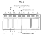
- FIG. 2 depicts a configuration of the vehicle control device shown in FIG. 1 .
- FIG. 3 is a cross-sectional diagram along a line A-A of FIG. 2 .
- FIG. 4 is another cross-sectional diagram along the line A-A of FIG. 2 .
- FIG. 5 is a schematic diagram of a vehicle having a vehicle control device according to a second embodiment of the present invention incorporated therein.
- FIG. 6 depicts a configuration of the vehicle control device shown in FIG. 5 .
- FIG. 7 is a cross-sectional diagram along a line B-B of FIG. 6 .
- FIG. 1 is a schematic diagram of a vehicle 100 having a vehicle control device according to a first embodiment of the present invention incorporated therein
- FIG. 2 depicts a configuration of the vehicle control device shown in FIG. 1
- FIG. 3 is a cross-sectional diagram along a line A-A of FIG. 2
- FIG. 4 is another cross-sectional diagram along the line A-A of FIG. 2 .
- FIG. 1 depicts the vehicle 100 that constitutes a formation of an electric vehicle (for example, a train) and a casing 1 A of the vehicle control device (hereinafter, simply “casing”) that is mounted under a floor of the vehicle 100 .
- This casing 1 A is formed in a rectangular shape that is long in a traveling direction of the electric vehicle and short on a side of a vehicle side, and is, for example, respectively arranged on a side of one vehicle side and a side of the other vehicle side under the floor of the vehicle 100 .
- FIG. 2 depicts the casing 1 A as viewed from a side of the vehicle 100 toward a railroad track side and an internal configuration of the vehicle control device.
- a first casing side-surface 22 of the casing 1 A is on a side of a vehicle side of the vehicle 100 and a second casing side-surface 23 of the casing 1 A is on a central side of the vehicle 100 .
- a machine installing chamber 9 that is formed on the side of the vehicle side, an in-casing air-circulating chamber (hereinafter, “circulating chamber”) 7 that is a space formed on the vehicle center side, and a plate-shaped partition plate 10 that is provided between the machine installing chamber 9 and the circulating chamber 7 are provided in the casing 1 A.
- a first through hole 30 and a second through hole 31 are formed in the partition plate 10 .
- the first through hole 30 is formed on a top surface side of the casing 1 A and allows an air in the machine installing chamber 9 to flow in the circulating chamber 7 .
- the second through hole 31 is formed on a bottom surface side of the casing 1 A and allows an air in the circulating chamber 7 to flow in the machine installing chamber 9 .
- a radiation fin 8 A is provided on a top surface of the circulating chamber 7 along the traveling direction of the electric vehicle.
- a radiation fin 8 B is provided on the second casing side-surface 23 on the vehicle center side along the traveling direction of the electric vehicle.
- the radiation fins 8 A and 8 B are a radiation fin for cooling an air B immediately after flowing in the circulating chamber 7 .
- a plurality of the radiation fins 8 A and 8 B are respectively provided in the traveling direction of the electric vehicle at a predetermined distance therebetween.
- the circulating chamber 7 is a space used when a machine such as a power conversion device 2 is assembled. For example, wires connected to various machines including the power conversion device 2 shown in FIG. 2 and the like are laid in the circulating chamber 7 . The power conversion device 2 and the like are checked by opening a checking door (not shown) provided on the first casing side-surface 22 .
- a sensor 5 monitors a voltage and a current that are input and output to and from the vehicle control device.
- the switchgear 3 performs electric connection and disconnection to and from an overhead line (not shown).
- the overvoltage suppression unit 4 includes a switching unit and a resistor (both not shown) to suppress an overvoltage.
- the power conversion device 2 is configured by a switching element (not shown) that is formed by silicon (Si), for example.
- the control unit 6 controls the entire vehicle control device.
- a switching element that configures the power conversion device 2 is not limited to a switching element formed by silicon (Si) and can be formed by a wide bandgap semiconductor having a larger bandgap than silicon.
- Examples of such semiconductors referred to as “wide bandgap semiconductor” include silicon carbide (SiC), gallium nitride (GaN), and diamond. Because a switching element formed by such a wide bandgap semiconductor has a high voltage resistance and a high allowable current density, the switching element can be downsized. By using a downsized switching element, a semiconductor module having the switching element incorporated therein can be downsized. Furthermore, because the wide bandgap semiconductor also has a high heat resistance, the semiconductor module can be further downsized. Further, because the wide bandgap semiconductor has a lower power loss, the efficiency of the switching element can be increased and the efficiency of the semiconductor module can be increased.
- the switching element formed by the wide bandgap semiconductor When the switching element formed by the wide bandgap semiconductor is used for the power conversion device 2 , a high temperature air generated from the switching element remains in a part of the machine installing chamber 9 , so that the lifetime of a filter capacitor and the like used for the power conversion device 2 may be reduced.
- the radiation fins 8 A and 8 B are arranged on a side of the circulating chamber 7 , that is, on the vehicle center side with respect to an extended line of ends of the partition plate 10 . This configuration is explained below in detail with reference to FIGS. 3 and 4 .
- a casing 1 A- 1 shown in FIG. 3 is an example of the casing 1 A shown in FIG. 2 , and only the radiation fin 8 A is arranged in the casing 1 A- 1 as an example.
- FIG. 3 depicts the power conversion device 2 , an air A heated by the power conversion device 2 , the air B that flows from the machine installing chamber 9 in the circulating chamber 7 and then flows down toward a side of a casing bottom surface 21 , an air C that flows from the circulating chamber 7 in the machine installing chamber 9 , and an air D that flows from the circulating chamber 7 in the machine installing chamber 9 .
- FIG. 3 depicts the power conversion device 2 that generates the largest amount of heat among various machines for convenience of explanation, a flow of the airs A to D in a case where the power conversion device 2 is used is the same as that in a case where the power conversion device 2 is replaced by a machine other than the power conversion device 2 .
- the partition plate 10 is interposed between the machine installing chamber 9 and the circulating chamber 7 .
- the first through hole 30 is formed on a side of a casing top surface 20 of the partition plate 10
- the second through hole 31 is formed on a side of the casing bottom surface 21 of the partition plate 10 .
- a relationship between the first through hole 30 , the second through hole 31 , the radiation fin 8 A, and the flow of the airs A to D is specifically explained below.
- the air A heated by the power conversion device 2 rises to the casing top surface 20 and flows along an inner side of the casing top surface 20 (an inner circumferential surface of the casing 1 A- 1 ) toward the side of the circulating chamber 7 .
- the first through hole 30 is formed near the center of the partition plate 10 , a flow of the air B from the machine installing chamber 9 to the circulating chamber 7 is blocked. Therefore, according to the vehicle control device of the first embodiment, the first through hole 30 is formed on the side of the casing top surface 20 (that is, between an inner circumferential surface of the casing top surface 20 and the partition plate 10 ) so as not to block the flow of the air B to the circulating chamber 7 .
- the air B that flows in the circulating chamber 7 flows down toward the side of the casing bottom surface 21 while being cooled in the circulating chamber 7 .
- the air C cooled in the circulating chamber 7 is not guided to a bottom surface side of the power conversion device 2 but flows in a side surface side of the power conversion device 2 (between the power conversion device 2 and the partition plate 10 ).
- heat may remain between the power conversion device 2 and the casing bottom surface 21 or between the power conversion device 2 and the first casing side-surface 22 .
- the second through hole 31 is formed on the side of the casing bottom surface 21 (between the casing bottom surface 21 and the partition plate 10 ).
- the vehicle control device is configured so as to positively utilize a natural convection effect based on a temperature difference for effectively cooling a machine that generates heat.
- the temperature of the air A having absorbed heat of the power conversion device 2 is 80° C., for example, this air A flows along the casing top surface 20 on the side of the machine installing chamber 9 into the circulating chamber 7 .
- the radiation fin 8 A is arranged on a top surface of the circulating chamber 7 , heat of the air B having flown in the circulating chamber 7 is absorbed by the radiation fin 8 A and the air B is cooled to approximately 60° C., for example.
- the temperature difference between the air B immediately after flowing in the circulating chamber 7 and the air C immediately before flowing in the machine installing chamber 9 is approximately 20° C.
- the air C cooled in the circulating chamber 7 then flows via the second through hole 31 in the machine installing chamber 9 .
- the air D having flown in the machine installing chamber 9 is transported to an upper side of the power conversion device 2 while absorbing heat of the power conversion device 2 , and guided again to the first through hole 30 as the air A.
- any radiation fin is not provided on the side of the machine installing chamber 9 , the air A is hardly cooled in the machine installing chamber 9 , but the air B having flown in the circulating chamber 7 is cooled by the radiation fin 8 A and thus the temperature difference between the air B and the air C is approximately 20° C. Accordingly, an air in the casing 1 A- 1 circulates by the natural convection effect based on the temperature difference through the machine installing chamber 9 , the first through hole 30 , the circulating chamber 7 , and the second through hole 31 in this order. As a result, heat-remaining in the machine installing chamber 9 is suppressed.
- this air A is cooled to approximately 70° C., for example, by a radiation fin (not shown) that is provided on a top surface of the machine installing chamber 9 and then flows in the circulating chamber 7 .
- a radiation fin (not shown) that is provided on a top surface of the machine installing chamber 9 and then flows in the circulating chamber 7 .
- heat of the air B having flown in the circulating chamber 7 is absorbed by the radiation fin 8 A and cooled to approximately 60° C., for example. Accordingly, the temperature difference between the air B immediately after flowing in the circulating chamber 7 and the air C is approximately 10° C.
- the temperature difference between the air B and the air C becomes smaller as compared to a case where the radiation fin 8 A is provided on a top side of the circulating chamber 7 , and thus the natural convection effect is reduced.
- a casing 1 A- 2 shown in FIG. 4 is an example of the casing 1 A shown in FIG. 2 .
- the radiation fin 8 A is provided on the top surface of the circulating chamber 7 and the radiation fin 8 B is provided on the second casing side-surface 23 on the vehicle center side.
- elements of the casing 1 A- 2 that are identical to those of the casing 1 A- 1 shown in FIG. 3 are denoted by like reference signs and explanations thereof will be omitted, and only elements of the casing 1 A- 2 that are different from those of the casing 1 A- 1 are described.
- an air in the casing 1 A- 2 circulates by the natural convection effect based on the temperature difference (approximately 25° C.) between the air B immediately after flowing in the circulating chamber 7 and the air C.
- the natural convection effect can be increased as compared to a case where only the radiation fin 8 A is arranged.
- the radiation fin 8 B is arranged on the entire second casing side-surface 23 as an example.
- the radiation fin 8 B is provided only on an upper side of the second casing side-surface 23 (an upper side with respect to a line that horizontally extends from near the center of the casing 1 A- 2 )
- the air B having flown in the circulating chamber 7 can be further cooled and as compared to a case where the radiation fin 8 B is provided on the entire second casing side-surface 23 , the number of radiation fins is reduced, so that the weight and the cost of the vehicle control device can be reduced.
- the vehicle control device includes the casing 1 A that is mounted on the vehicle 100 of an electric vehicle, the machine installing chamber 9 that is provided on a side of a vehicle side in the casing 1 A and in which a machine that controls the electric vehicle is installed, the circulating chamber 7 that is provided on a vehicle center side in the casing 1 A, the partition plate 10 that is provided between the machine installing chamber 9 and the circulating chamber 7 and in which the first through hole 30 that is formed on a top surface side of the casing 1 A and allows the air A in the machine installing chamber 9 to flow in the circulating chamber 7 and the second through hole 31 that is formed on a bottom surface side of the casing 1 A and allows the air C in the circulating chamber 7 to flow in the machine installing chamber 9 are formed, and the radiators 8 A and 8 B that are provided on a top of the circulating chamber 7 and radiate heat of the air B that flows via the first through hole 30 in the circulating chamber 7 by a traveling wind of the electric vehicle.
- the temperature difference between the air B immediately after flowing in the circulating chamber 7 and the air C can be increased and the airs A to D in the casing 1 A circulate by a natural convection effect based on the temperature difference. Therefore, heat generated from a machine such as the power conversion device 2 does not remain in a part thereof. As a result, it is possible to suppress a decrease in the lifetime of a filter capacitor and the like used for the power conversion device 2 .
- the vehicle control device of the first embodiment even when a fan and the like are not installed in the casing 1 A, the airs A to D in the casing 1 A can be circulated. Accordingly, an empty space in the vehicle control device is not reduced and an increase in the temperature in a casing due to heat generated from a fan can be prevented. As a result, it is possible to suppress a decrease in the lifetime of the filter capacitor described above and the like and the casing 1 A can be downsized.
- FIG. 5 is a schematic diagram of the vehicle 100 having a vehicle control device according to a second embodiment of the present invention incorporated therein.
- FIG. 6 depicts a configuration of the vehicle control device shown in FIG. 5 .
- FIG. 7 is a cross-sectional diagram along a line B-B of FIG. 6 .
- the vehicle control device according to the second embodiment is different from the vehicle control device according to the first embodiment in the shape of casing and the position to which a radiation fin is mounted.
- FIG. 5 depicts a casing 1 B of the vehicle control device that is mounted under the floor of the vehicle 100 .
- the casing 1 B is formed in a rectangular shape that is long in a transverse width direction and short in a traveling direction of the vehicle 100 .
- FIG. 6 depicts the casing 1 B as viewed from a side of the vehicle 100 toward a railroad track side and an internal configuration of the vehicle control device.
- a first casing side-surface 30 A of the casing 1 B is on a side of one vehicle side of the vehicle 100 and a second casing side-surface 30 B is on a side of the other vehicle side of the vehicle 100 .
- a first machine installing chamber 9 A that is formed on a side of the first casing side-surface 30 A, a second machine installing chamber 9 B that is formed on a side of the second casing side-surface 30 B, and a circulating chamber 70 that is provided between the first machine installing chamber 9 A and the second machine installing chamber 9 B are provided in the casing 1 B.
- a first partition plate 10 A is provided between the first machine installing chamber 9 A and the circulating chamber 70 .
- a first through hole 30 a and a second through hole 31 a are formed in the first partition plate 10 A.
- the first through hole 30 a is formed on a top surface side of the casing 1 B and allows the air A in the first machine installing chamber 9 A to flow in the circulating chamber 70 .
- the second through hole 31 a is formed on a bottom surface side of the casing 1 B and allows the air C in the circulating chamber 70 to flow in the first machine installing chamber 9 A.
- a second partition plate 10 B is provided between the second machine installing chamber 9 B and the circulating chamber 70 .
- a third through hole 30 b and a fourth through hole 31 B are formed in the second partition plate 10 B.
- the third through hole 30 b is formed on the top surface side of the casing 1 B and allows the air A in the second machine installing chamber 9 B to flow in the circulating chamber 70 .
- a fourth through hole 31 b is formed on the bottom surface side of the casing 1 B and allows the air C in the circulating chamber 70 to flow in the second machine installing chamber 9 B.
- control unit 6 the power conversion device 2 , the overvoltage suppression unit 4 , the switchgear 3 , and the sensor 5 are installed in the casing 1 B.
- the control unit 6 and the power conversion device 2 are installed in the first machine installing chamber 9 A shown in FIG. 6 .
- the overvoltage suppression unit 4 , the switchgear 3 , and the sensor 5 are installed in the second machine installing chamber 9 B.
- the power conversion device 2 that is configured by a switching element (not shown) formed by, for example, silicon (Si) is provided in either the first machine installing chamber 9 A or the second machine installing chamber 9 B.
- a switching element that configures the power conversion device 2 is not limited to the switching element formed by silicon (Si) and can be formed by a wide bandgap semiconductor having a larger bandgap than silicon.
- the circulating chamber 70 is a space used at the time of an operation of assembling the power conversion device 2 and the like.
- the power conversion device 2 and the control unit 6 are arranged in the first machine installing chamber 9 A.
- the sensor 5 , the switchgear 3 , and the overvoltage suppression unit 4 are arranged in the second machine installing chamber 9 B.
- a radiation fin 80 is provided on a top of the circulating chamber 70 along a traveling direction of an electric vehicle.
- the radiation fin 80 is a radiation fin for cooling the air B immediately after flowing in the circulating chamber 70 .
- a plurality of the radiation fins 80 are provided in the traveling direction of the electric vehicle at a predetermined distance therebetween.
- the radiation fin 80 is arranged on a side of the circulating chamber 70 , that is, between an extended line of the first partition plate 10 A and an extended line of the second partition plate 10 B (on a vehicle center side). This configuration is explained below in detail with reference to FIG. 7 .
- FIG. 7 depicts the air A heated by, for example, the power conversion device 2 and the switchgear 3 , the air B that flows from the first and second machine installing chambers 9 A and 9 B in the circulating chamber 70 , the air C guided from the circulating chamber 70 to the first and second machine installing chambers 9 A and 9 B, and the air D that flows from the circulating chamber 70 in the first and second machine installing chambers 9 A and 9 B.
- the first partition plate 10 A is interposed between the first machine installing chamber 9 A and the circulating chamber 70
- the second partition plate 10 B is interposed between the second machine installing chamber 9 B and the circulating chamber 70 .
- the first through hole 30 a is formed on a side of the casing top surface 20 of the first partition plate 10 A, and the third through hole 30 h is formed on the side of the casing top surface 20 of the second partition plate 10 B.
- the second through hole 31 a is formed on a side of the casing bottom surface 21 of the first partition plate 10 A, and the fourth through hole 31 b is formed on the side of the casing bottom surface 21 of the second partition plate 10 B.
- a relationship between the first and second through holes 30 a and 31 a , the radiation fin 80 , and a flow of the airs A to D is specifically explained below.
- a mode in which the airs A to D circulate between the first machine installing chamber 9 A and the circulating chamber 70 is explained, and explanations of a mode in which the airs A to D circulate between the second machine installing chamber 9 B and the circulating chamber 70 will be omitted.
- the air A heated by the power conversion device 2 rises to the casing top surface 20 and flows along an inner side of the casing top surface 20 (an inner circumferential surface of the casing 1 B) toward a side of the circulating chamber 70 .
- the first through hole 30 a and the third through hole 30 b are formed near the respective centers of the first partition plate 10 A and the second partition plate 10 B, a flow of the air B from the first machine installing chamber 9 A to the circulating chamber 70 is blocked.
- the first through hole 30 a and the third through hole 30 b are formed on a side of the casing top surface 20 (that is, between an inner circumferential surface of the casing top surface 20 and the first partition plate 10 A and the second partition plate 10 B) so as not to block the flow of the air B flowing in the circulating chamber 70 .
- the air B that flows in the circulating chamber 70 is cooled in the circulating chamber 70 and flows down toward a side of the casing bottom surface 21 .
- the air C cooled in the circulating chamber 70 is not guided to a bottom surface side of the power conversion device 2 but flows in a side surface side of the power conversion device 2 (between the power conversion device 2 and the partition plate 10 ).
- heat may remain between the power conversion device 2 and the casing bottom surface 21 or between the power conversion device 2 and the first casing side-surface 30 A.
- the second through hole 31 a and the fourth through hole 31 b are formed on the side of the casing bottom surface 21 (between the casing bottom surface 21 and the partition plate 10 A). Similarly, the fourth through hole 31 b is formed between the casing bottom surface 21 and the partition plate 10 B.
- the vehicle control device is configured so as to positively utilize a natural convection effect based on the temperature difference between the air B and the air C for effectively cooling a machine that generates heat.
- the temperature of the air A having absorbed heat of the power conversion device 2 is 80° C., for example, this air A flows along the casing top surface 20 on the side of the first machine installing chamber 9 A into the circulating chamber 70 .
- FIG. 7 when the radiation fin 80 is arranged on a top surface of the circulating chamber 70 , heat of the air B having flown in the circulating chamber 70 is absorbed by the radiation fin 80 and cooled to approximately 60° C., for example.
- the temperature difference between the air B immediately after flowing in the circulating chamber 70 and the air C immediately before flowing in the first machine installing chamber 9 A is approximately 20° C.
- the air C cooled in the circulating chamber 70 flows via the second through hole 31 a in the first machine installing chamber 9 A.
- the air D having flown in the first machine installing chamber 9 A absorbs heat of the power conversion device 2 when passing outside or inside the power conversion device 2 , and the air D is transported to an upper side of the power conversion device 2 , and guided again to the first through hole 30 a.
- any radiation fin is not provided on the side of the first machine installing chamber 9 A, the air A is hardly cooled in the first machine installing chamber 9 A, but the air B having flown in the circulating chamber 7 is cooled by the radiation fin 80 and thus the temperature difference between the air B and the air C is approximately 20° C. Accordingly, an air in the casing 1 B circulates by the natural convection effect based on the temperature difference through the first machine installing chamber 9 A, the first through hole 30 a , the circulating chamber 70 , and the second through hole 31 a in this order. As a result, heat-remaining in the first machine installing chamber 9 A is suppressed.
- this air A is cooled to approximately 70° C., for example, by a radiation fin (not shown) that is provided on a top surface of the first machine installing chamber 9 A and then flows in the circulating chamber 70 .
- a radiation fin (not shown) that is provided on a top surface of the first machine installing chamber 9 A and then flows in the circulating chamber 70 .
- heat of the air B having flown in the circulating chamber 70 is absorbed by the radiation fin 80 to be cooled to approximately 60° C., for example. Accordingly, the temperature difference between the air B immediately after flowing in the circulating chamber 70 and the air C is approximately 10° C.
- the vehicle control device includes the casing 1 B that is mounted on a vehicle of an electric vehicle, the first machine installing chamber 9 A that is provided on a side of one vehicle side in the casing 1 B (on a side of the first casing side-surface 30 A) and in which a machine that controls the electric vehicle is installed, the second machine installing chamber 9 B that is provided on a side of the other vehicle side in the casing 1 B (on a side of the second casing side-surface 30 B) and in which a machine that controls the electric vehicle is installed, the circulating chamber 70 that is provided between the first machine installing chamber 9 A and the second machine installing chamber 9 B, the first partition plate 10 A that is provided between the first machine installing chamber 9 A and the circulating chamber 70 and in which the first through hole 30 a that is formed on a top surface side of the casing 1 B and allows the air A in the first machine installing chamber 9 A to flow in the circulating chamber 70 and the second through hole 31 a that is formed on a bottom surface side of the casing
- the temperature difference between the air B and the air C can be increased and the airs A to D in the casing 1 B circulate by a natural convection effect based on the temperature difference.
- Heat generated from a machine such as the power conversion device 2 does not remain in a part of the first machine installing chamber 9 A or the second machine installing chamber 9 B.
- the vehicle control device of the second embodiment even when a fan and the like are not installed in the casing 1 B, the airs A to D can be circulated.
- a fin-shaped radiator (the radiation fin 8 A, the radiation fin 8 B, and the radiation fin 80 ) is used for cooling the air B having flown in the circulating chambers 7 and 70 .
- these radiators are not limited to the fin-shaped radiator as long as they have heat conductivity and are cooled by a traveling wind of the vehicle 100 .
- the through hole ( 30 , 30 a , 30 b , 31 , 31 a , and 31 b ) is formed by machining a part of the partition plate ( 10 , 10 A, and 10 B) and the shape of the through hole ( 30 , 30 a , 30 b , 31 , 31 a , and 31 b ) is, for example, an ellipse or a rectangle that is long in a traveling direction of an electric vehicle.
- the position of the through hole ( 30 , 30 a , 30 b , 31 , 31 a , 31 b ) with respect to the traveling direction of the electric vehicle is a position that does not block natural convection of the airs A to D.
- the power conversion device 2 When the power conversion device 2 according to the first and second embodiments is configured by a switching element that uses a wide bandgap semiconductor, the temperature of the air A heated by the power conversion device 2 becomes higher, and thus the temperature difference between the air B and the air C becomes large and a natural convection effect can be further improved.
- the present invention can be applied to a vehicle control device that is mounted under a floor of an electric vehicle, and is particularly useful as an invention that can suppress a decrease in the lifetime of a machine without using any fan.
Landscapes
- Engineering & Computer Science (AREA)
- Microelectronics & Electronic Packaging (AREA)
- Thermal Sciences (AREA)
- Physics & Mathematics (AREA)
- Mechanical Engineering (AREA)
- Transportation (AREA)
- Automation & Control Theory (AREA)
- Cooling Or The Like Of Electrical Apparatus (AREA)
- Arrangement Or Mounting Of Propulsion Units For Vehicles (AREA)
- Battery Mounting, Suspending (AREA)
- Secondary Cells (AREA)
- Electric Propulsion And Braking For Vehicles (AREA)
- Inverter Devices (AREA)
Applications Claiming Priority (1)
| Application Number | Priority Date | Filing Date | Title |
|---|---|---|---|
| PCT/JP2011/055208 WO2012120610A1 (fr) | 2011-03-07 | 2011-03-07 | Dispositif de commande pour véhicule |
Publications (2)
| Publication Number | Publication Date |
|---|---|
| US20130320826A1 US20130320826A1 (en) | 2013-12-05 |
| US9320158B2 true US9320158B2 (en) | 2016-04-19 |
Family
ID=45851209
Family Applications (1)
| Application Number | Title | Priority Date | Filing Date |
|---|---|---|---|
| US13/985,720 Active 2031-05-20 US9320158B2 (en) | 2011-03-07 | 2011-03-07 | Vehicle control device |
Country Status (4)
| Country | Link |
|---|---|
| US (1) | US9320158B2 (fr) |
| JP (1) | JP4879370B1 (fr) |
| CN (1) | CN103415431B (fr) |
| WO (1) | WO2012120610A1 (fr) |
Cited By (1)
| Publication number | Priority date | Publication date | Assignee | Title |
|---|---|---|---|---|
| DE112017007352B4 (de) | 2017-03-29 | 2021-12-23 | Mitsubishi Electric Corporation | Antriebssteuervorrichtung |
Families Citing this family (11)
| Publication number | Priority date | Publication date | Assignee | Title |
|---|---|---|---|---|
| CN103533810B (zh) * | 2013-09-27 | 2017-01-25 | 山东和顺电气有限公司 | 一种中低速悬浮列车悬浮控制器散热装置及其工作方法 |
| JP6213386B2 (ja) * | 2014-06-16 | 2017-10-18 | 株式会社デンソー | 電子制御装置 |
| FR3024420B1 (fr) * | 2014-08-04 | 2016-09-02 | Alstom Transp Tech | Coffre de traction d'un vehicule ferroviaire et vehicule ferroviaire associe |
| JP6258165B2 (ja) * | 2014-09-05 | 2018-01-10 | 株式会社東芝 | ゲート駆動回路、半導体装置、及び電力変換装置 |
| CN104340235A (zh) * | 2014-11-04 | 2015-02-11 | 株洲南车时代电气股份有限公司 | 整车控制装置 |
| US20170082124A1 (en) * | 2015-06-18 | 2017-03-23 | Kevin Kremeyer | Directed Energy Deposition to Facilitate High Speed Applications |
| JP2017024505A (ja) * | 2015-07-21 | 2017-02-02 | 東洋電機製造株式会社 | 車両用駆動制御装置 |
| DE112016006653B4 (de) * | 2016-03-25 | 2024-01-18 | Mitsubishi Electric Corporation | Fahrzeugsteuervorrichtung |
| JP6733285B2 (ja) * | 2016-04-27 | 2020-07-29 | 富士電機株式会社 | 鉄道車両用電力変換装置 |
| EP3439445A1 (fr) * | 2017-07-31 | 2019-02-06 | Siemens Aktiengesellschaft | Dissipation thermique des commutateurs de puissance semi-conducteurs à large bande dans un convertisseur électrique |
| CN112822895B (zh) * | 2020-12-31 | 2022-03-11 | 高特电驱动科技(徐州)有限公司 | 一种电动车控制器高温冷却装置 |
Citations (22)
| Publication number | Priority date | Publication date | Assignee | Title |
|---|---|---|---|---|
| DE2757282A1 (de) * | 1977-12-22 | 1979-07-05 | Licentia Gmbh | Thermische barrieren in elektrischen, elektronischen oder mechanischen geraeten, insbesondere kompaktgeraeten mit begrenzten flaechen |
| DE3717009A1 (de) * | 1987-05-21 | 1988-12-15 | Philips Patentverwaltung | Funkgeraet fuer eine mobilfunkanlage |
| US4976327A (en) * | 1989-02-14 | 1990-12-11 | Globe-Union Inc. | Battery module for the engine compartment of an automobile |
| JPH08192654A (ja) | 1995-01-17 | 1996-07-30 | Toshiba Transport Eng Kk | 車両用半導体制御装置 |
| US5542489A (en) * | 1995-05-31 | 1996-08-06 | Ford Motor Company | Battery thermal chamber |
| JPH10212949A (ja) | 1997-01-30 | 1998-08-11 | Toshiba Transport Eng Kk | 車両用半導体制御装置 |
| JP2001114100A (ja) | 1999-10-21 | 2001-04-24 | Toshiba Transport Eng Inc | 車両用制御装置 |
| US20030047366A1 (en) * | 2001-07-10 | 2003-03-13 | Johnson Controls Technology Company | Module for battery and/or other vehicle components |
| US20040094115A1 (en) * | 2002-08-30 | 2004-05-20 | Trw Automotive Electronics & Components Gmbh & Co. Kg | Assembly for cooling a control module and a battery |
| US20040169956A1 (en) * | 2001-12-27 | 2004-09-02 | Fujitsu Limited | Storage device unit including cooling device |
| US6828755B1 (en) * | 2001-10-15 | 2004-12-07 | Johnson Controls Technology Company | Battery system module |
| JP2005223277A (ja) | 2004-02-09 | 2005-08-18 | Toshiba Corp | 鉄道車両用電力変換装置 |
| DE102004030457A1 (de) * | 2004-06-24 | 2006-01-12 | Sma Technologie Ag | Wechselrichter mit einem Gehäuse mit einem Kühlaggregat |
| US7045236B1 (en) * | 2001-08-10 | 2006-05-16 | Johnson Controls Technology Company | Heat and gas exchange system for battery |
| JP2006304466A (ja) | 2005-04-19 | 2006-11-02 | Toshiba Corp | 電気車制御装置及びそれを用いた電気車 |
| JP2007095975A (ja) | 2005-09-29 | 2007-04-12 | National Institute Of Advanced Industrial & Technology | ダイヤモンドパワー半導体デバイス及びその製造方法 |
| US7231994B2 (en) * | 2003-11-24 | 2007-06-19 | Daimlerchrysler Corporation | Hybrid vehicle with integral generator for auxiliary loads |
| DE102008037372A1 (de) * | 2008-09-18 | 2010-04-01 | Lear Corporation Gmbh | Gehäuse für temperatursensible Komponenten |
| US20100254087A1 (en) | 2009-03-23 | 2010-10-07 | Converteam Technology Ltd. | Electric module |
| US8035964B2 (en) * | 2008-01-16 | 2011-10-11 | Intelligent Electronic Systems | Multi-position housing made of metal extruded section member for manufacturing a waterproof power electronic device |
| US8556017B2 (en) * | 2008-02-07 | 2013-10-15 | Honda Motor Co., Ltd. | Vehicular power supply system |
| US20150146380A1 (en) * | 2013-11-26 | 2015-05-28 | Delta Electronics (Shanghai) Co., Ltd. | Electronic device and method for assembling the same |
Family Cites Families (2)
| Publication number | Priority date | Publication date | Assignee | Title |
|---|---|---|---|---|
| JPS5820541A (ja) * | 1981-07-30 | 1983-02-07 | Toyoda Gosei Co Ltd | ゴム製トリム |
| WO2009011162A1 (fr) * | 2007-07-19 | 2009-01-22 | Mitsubishi Heavy Industries, Ltd. | Structure de montage de batterie pour tramway électrique |
-
2011
- 2011-03-07 WO PCT/JP2011/055208 patent/WO2012120610A1/fr not_active Ceased
- 2011-03-07 JP JP2011532392A patent/JP4879370B1/ja active Active
- 2011-03-07 US US13/985,720 patent/US9320158B2/en active Active
- 2011-03-07 CN CN201180069019.6A patent/CN103415431B/zh active Active
Patent Citations (22)
| Publication number | Priority date | Publication date | Assignee | Title |
|---|---|---|---|---|
| DE2757282A1 (de) * | 1977-12-22 | 1979-07-05 | Licentia Gmbh | Thermische barrieren in elektrischen, elektronischen oder mechanischen geraeten, insbesondere kompaktgeraeten mit begrenzten flaechen |
| DE3717009A1 (de) * | 1987-05-21 | 1988-12-15 | Philips Patentverwaltung | Funkgeraet fuer eine mobilfunkanlage |
| US4976327A (en) * | 1989-02-14 | 1990-12-11 | Globe-Union Inc. | Battery module for the engine compartment of an automobile |
| JPH08192654A (ja) | 1995-01-17 | 1996-07-30 | Toshiba Transport Eng Kk | 車両用半導体制御装置 |
| US5542489A (en) * | 1995-05-31 | 1996-08-06 | Ford Motor Company | Battery thermal chamber |
| JPH10212949A (ja) | 1997-01-30 | 1998-08-11 | Toshiba Transport Eng Kk | 車両用半導体制御装置 |
| JP2001114100A (ja) | 1999-10-21 | 2001-04-24 | Toshiba Transport Eng Inc | 車両用制御装置 |
| US20030047366A1 (en) * | 2001-07-10 | 2003-03-13 | Johnson Controls Technology Company | Module for battery and/or other vehicle components |
| US7045236B1 (en) * | 2001-08-10 | 2006-05-16 | Johnson Controls Technology Company | Heat and gas exchange system for battery |
| US6828755B1 (en) * | 2001-10-15 | 2004-12-07 | Johnson Controls Technology Company | Battery system module |
| US20040169956A1 (en) * | 2001-12-27 | 2004-09-02 | Fujitsu Limited | Storage device unit including cooling device |
| US20040094115A1 (en) * | 2002-08-30 | 2004-05-20 | Trw Automotive Electronics & Components Gmbh & Co. Kg | Assembly for cooling a control module and a battery |
| US7231994B2 (en) * | 2003-11-24 | 2007-06-19 | Daimlerchrysler Corporation | Hybrid vehicle with integral generator for auxiliary loads |
| JP2005223277A (ja) | 2004-02-09 | 2005-08-18 | Toshiba Corp | 鉄道車両用電力変換装置 |
| DE102004030457A1 (de) * | 2004-06-24 | 2006-01-12 | Sma Technologie Ag | Wechselrichter mit einem Gehäuse mit einem Kühlaggregat |
| JP2006304466A (ja) | 2005-04-19 | 2006-11-02 | Toshiba Corp | 電気車制御装置及びそれを用いた電気車 |
| JP2007095975A (ja) | 2005-09-29 | 2007-04-12 | National Institute Of Advanced Industrial & Technology | ダイヤモンドパワー半導体デバイス及びその製造方法 |
| US8035964B2 (en) * | 2008-01-16 | 2011-10-11 | Intelligent Electronic Systems | Multi-position housing made of metal extruded section member for manufacturing a waterproof power electronic device |
| US8556017B2 (en) * | 2008-02-07 | 2013-10-15 | Honda Motor Co., Ltd. | Vehicular power supply system |
| DE102008037372A1 (de) * | 2008-09-18 | 2010-04-01 | Lear Corporation Gmbh | Gehäuse für temperatursensible Komponenten |
| US20100254087A1 (en) | 2009-03-23 | 2010-10-07 | Converteam Technology Ltd. | Electric module |
| US20150146380A1 (en) * | 2013-11-26 | 2015-05-28 | Delta Electronics (Shanghai) Co., Ltd. | Electronic device and method for assembling the same |
Non-Patent Citations (3)
| Title |
|---|
| *International Search Report (PCT/ISA/210) issued on May 24, 2011, by the Japanese Patent Office as the International Searching Authority for International Application No. PCT/JP2011/055208. |
| *Written Opinion (PCT/ISA/237) issued on May 24, 2011, by the Japanese Patent Office as the International Searching Authority for International Application No. PCT/JP2011/055208. |
| Office Action (First) issued on Feb. 28, 2015, by the Chinese Patent Office in corresponding Chinese Patent Application No. 201180069019.6 with English translation thereof. (10 pgs). |
Cited By (2)
| Publication number | Priority date | Publication date | Assignee | Title |
|---|---|---|---|---|
| DE112017007352B4 (de) | 2017-03-29 | 2021-12-23 | Mitsubishi Electric Corporation | Antriebssteuervorrichtung |
| US11737235B2 (en) | 2017-03-29 | 2023-08-22 | Mitsubishi Electric Corporation | Propulsion control device |
Also Published As
| Publication number | Publication date |
|---|---|
| WO2012120610A1 (fr) | 2012-09-13 |
| JP4879370B1 (ja) | 2012-02-22 |
| JPWO2012120610A1 (ja) | 2014-07-07 |
| US20130320826A1 (en) | 2013-12-05 |
| CN103415431A (zh) | 2013-11-27 |
| CN103415431B (zh) | 2015-12-02 |
Similar Documents
| Publication | Publication Date | Title |
|---|---|---|
| US9320158B2 (en) | Vehicle control device | |
| CN101834560B (zh) | 用于电动机控制器的装置 | |
| KR102519046B1 (ko) | 수냉식 배터리 시스템의 냉각수 온도 조절 장치 및 방법 | |
| US9730365B2 (en) | Heat sink apparatus and method for power semiconductor device module | |
| KR101630496B1 (ko) | 냉동 사이클 장치 및 실외 열원 유닛 | |
| US10178814B2 (en) | Inverter and method for cooling an inverter | |
| US20130301328A1 (en) | Power conversion apparatus | |
| JP5827513B2 (ja) | スイッチング電源装置 | |
| KR101449828B1 (ko) | 철도 차량용 전력 변환 장치의 냉각기 | |
| JP6867432B2 (ja) | 電力変換装置 | |
| FI126026B (fi) | Tehoelektroniikkalaite ja sen jäähdytysjärjestely | |
| KR101606456B1 (ko) | 전지모듈 | |
| WO2015194259A1 (fr) | Refroidisseur et procédé de fixation de refroidisseur | |
| US20130292091A1 (en) | Cooler | |
| KR101541181B1 (ko) | 전기자동차용 전력 변환 장치 | |
| CN203279443U (zh) | 电控箱及具有该电控箱的空调器 | |
| JP2013230010A (ja) | 電力変換装置 | |
| JP6074346B2 (ja) | 配電盤装置 | |
| JP2014220334A (ja) | 電力変換装置 | |
| JP2010284033A (ja) | 鉄道車両の電源装置 | |
| KR20130106240A (ko) | 전기차 추진 제어장치 | |
| CN107294356B (zh) | 电力变换装置 | |
| CN101459375A (zh) | 牵引变流装置 | |
| US10939586B2 (en) | Heat exchanger structure for a rack assembly | |
| JP6764585B2 (ja) | 電力変換装置 |
Legal Events
| Date | Code | Title | Description |
|---|---|---|---|
| AS | Assignment |
Owner name: MITSUBISHI ELECTRIC CORPORATION, JAPAN Free format text: ASSIGNMENT OF ASSIGNORS INTEREST;ASSIGNOR:IKEMOTO, MINORU;REEL/FRAME:031018/0899 Effective date: 20130628 |
|
| STCF | Information on status: patent grant |
Free format text: PATENTED CASE |
|
| MAFP | Maintenance fee payment |
Free format text: PAYMENT OF MAINTENANCE FEE, 4TH YEAR, LARGE ENTITY (ORIGINAL EVENT CODE: M1551); ENTITY STATUS OF PATENT OWNER: LARGE ENTITY Year of fee payment: 4 |
|
| MAFP | Maintenance fee payment |
Free format text: PAYMENT OF MAINTENANCE FEE, 8TH YEAR, LARGE ENTITY (ORIGINAL EVENT CODE: M1552); ENTITY STATUS OF PATENT OWNER: LARGE ENTITY Year of fee payment: 8 |