WO2012120610A1 - Dispositif de commande pour véhicule - Google Patents
Dispositif de commande pour véhicule Download PDFInfo
- Publication number
- WO2012120610A1 WO2012120610A1 PCT/JP2011/055208 JP2011055208W WO2012120610A1 WO 2012120610 A1 WO2012120610 A1 WO 2012120610A1 JP 2011055208 W JP2011055208 W JP 2011055208W WO 2012120610 A1 WO2012120610 A1 WO 2012120610A1
- Authority
- WO
- WIPO (PCT)
- Prior art keywords
- housing
- air
- chamber
- hole
- circulation chamber
- Prior art date
- Legal status (The legal status is an assumption and is not a legal conclusion. Google has not performed a legal analysis and makes no representation as to the accuracy of the status listed.)
- Ceased
Links
Images


Classifications
-
- B—PERFORMING OPERATIONS; TRANSPORTING
- B61—RAILWAYS
- B61C—LOCOMOTIVES; MOTOR RAILCARS
- B61C17/00—Arrangement or disposition of parts; Details or accessories not otherwise provided for; Use of control gear and control systems
-
- H—ELECTRICITY
- H05—ELECTRIC TECHNIQUES NOT OTHERWISE PROVIDED FOR
- H05K—PRINTED CIRCUITS; CASINGS OR CONSTRUCTIONAL DETAILS OF ELECTRIC APPARATUS; MANUFACTURE OF ASSEMBLAGES OF ELECTRICAL COMPONENTS
- H05K7/00—Constructional details common to different types of electric apparatus
- H05K7/20—Modifications to facilitate cooling, ventilating, or heating
- H05K7/20009—Modifications to facilitate cooling, ventilating, or heating using a gaseous coolant in electronic enclosures
- H05K7/20127—Natural convection
-
- H—ELECTRICITY
- H05—ELECTRIC TECHNIQUES NOT OTHERWISE PROVIDED FOR
- H05K—PRINTED CIRCUITS; CASINGS OR CONSTRUCTIONAL DETAILS OF ELECTRIC APPARATUS; MANUFACTURE OF ASSEMBLAGES OF ELECTRICAL COMPONENTS
- H05K7/00—Constructional details common to different types of electric apparatus
- H05K7/20—Modifications to facilitate cooling, ventilating, or heating
- H05K7/2089—Modifications to facilitate cooling, ventilating, or heating for power electronics, e.g. for inverters for controlling motor
- H05K7/20909—Forced ventilation, e.g. on heat dissipaters coupled to components
Definitions
- the present invention relates to a vehicle control device that is attached to the bottom of an electric vehicle.
- a power conversion device such as a so-called inverter using a power semiconductor element
- fins for effectively radiating heat generated from each device.
- SiC silicon carbide
- the housing uses a method for releasing heat generated from the power converter using a heat radiating fin to the outside of the apparatus, or an air circulation fan disposed in the apparatus. Techniques such as reducing the temperature inside the body have been adopted.
- Patent Document 1 it is not a device arrangement that takes into account natural convection in the housing (high-temperature air moves to the top of the heating element while low-temperature air is guided to the heating element). For this reason, for example, a portion where the heat generated from the power conversion device stays in part causes a temperature increase to occur, and there is a problem that the life of a filter capacitor used in the power conversion device is shortened.
- the above-described method for reducing the temperature in the housing using the fan is used, not only the free space in the vehicle control device is reduced, but also the temperature inside the housing is increased by the heat generated from the fan itself. As the temperature rises, there is a problem that the lifetime of the fan self-confidence and the lifetime of the filter capacitor described above are shortened.
- the present invention has been made in view of the above, and an object of the present invention is to obtain a vehicle control device that can suppress a reduction in the life of an apparatus without using a fan.
- the present invention provides a housing attached to a vehicle of an electric vehicle, and a device that is provided on the vehicle side in the housing and controls the electric vehicle.
- a device installation chamber an air circulation chamber provided on the vehicle center side in the housing, and provided between the device installation chamber and the air circulation chamber and formed on the upper surface side of the housing.
- a first through hole that allows the air in the installation chamber to flow into the air circulation chamber
- a second through hole that is formed on the lower surface side of the housing and allows the air in the air circulation chamber to flow into the device installation chamber.
- a partition plate formed, and a heat dissipator that is provided at an upper portion of the air circulation chamber and that radiates heat of the air flowing into the air circulation chamber through the first through-hole by running wind of the electric vehicle, , Provided.
- the life of the equipment can be obtained without using a fan.
- the effect that the fall of can be suppressed is produced.
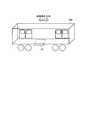
- FIG. 1 is a diagram schematically illustrating a vehicle equipped with the vehicle control device according to the first embodiment of the present invention.
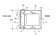
- FIG. 2 is a diagram showing a configuration of the vehicle control device shown in FIG.
- FIG. 3 is a cross-sectional view taken along line AA in FIG.
- FIG. 4 is another cross-sectional view taken along line AA in FIG.
- FIG. 5 is a diagram schematically illustrating a vehicle equipped with the vehicle control device according to the second embodiment of the present invention.
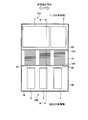
- FIG. 6 is a diagram showing a configuration of the vehicle control device shown in FIG.
- FIG. 7 is a cross-sectional view taken along line BB in FIG.
- FIG. 1 is a diagram schematically showing a vehicle 100 equipped with a vehicle control device according to a first embodiment of the present invention
- FIG. 2 is a diagram showing the configuration of the vehicle control device shown in FIG. 3 is a cross-sectional view taken along the line AA in FIG. 2
- FIG. 4 is another cross-sectional view taken along the line AA in FIG.
- FIG. 1 shows one vehicle 100 constituting an organization of an electric vehicle (for example, a train), and a housing (hereinafter simply referred to as “housing”) of a vehicle control device attached under the floor of the vehicle 100. 1A) is shown.
- the housing 1A is formed in a rectangular shape that is long in the traveling direction of the electric vehicle and short on the vehicle side (chastling). For example, under the floor of the vehicle 100, one vehicle side and the other Are arranged on the vehicle side.
- FIG. 2 shows the housing 1A when the track side is viewed from the vehicle 100 side and the internal configuration of the vehicle control device.
- the first housing side surface 22 of the housing 1 ⁇ / b> A is the vehicle side of the vehicle 100
- the second housing side surface 23 of the housing 1 ⁇ / b> A is the center side of the vehicle 100.
- an equipment installation chamber 9 formed on the vehicle side an air circulation chamber (hereinafter referred to as “circulation chamber”) 7 which is a space formed on the vehicle center side, and equipment installation A plate-like partition plate 10 provided between the chamber 9 and the circulation chamber 7 is provided.
- the partition plate 10 includes a first through hole 30 formed on the upper surface side of the housing 1 ⁇ / b> A and allowing air in the device installation chamber 9 to flow into the circulation chamber 7, and a lower surface of the housing 1 ⁇ / b> A.
- a second through hole 31 that is formed on the side and allows the air in the circulation chamber 7 to flow into the device installation chamber 9 is formed.
- heat radiation fins 8A are provided on the upper surface of the circulation chamber 7 along the traveling direction of the electric vehicle, and the heat radiation fins 8B are disposed on the second casing side surface 23 on the vehicle center side along the traveling direction of the electric vehicle. Is provided.
- the heat radiating fins 8A and the heat radiating fins 8B are heat radiating fins for cooling the air B immediately after flowing into the circulation chamber 7, and a plurality of the heat radiating fins 8A and 8B are provided at predetermined intervals in the traveling direction of the electric vehicle as shown in FIG.
- the circulation chamber 7 is a space used when assembling devices such as the power conversion device 2.
- the circulation chamber 7 has wirings connected to various devices such as the power conversion device 2 shown in FIG. 2. Is laid.
- it is performed by opening the inspection port (not shown) provided in the 1st housing
- the switching element which comprises the power converter device 2 is not limited to what was formed with silicon (Si), You may form with a wide band gap semiconductor with a large band gap compared with silicon.
- the semiconductor referred to as the wide band gap semiconductor include silicon carbide (SiC), gallium nitride (GaN), and diamond.
- a switching element formed of such a wide band gap semiconductor has a high voltage resistance and a high allowable current density. Therefore, the switching element can be miniaturized. By using the miniaturized switching element, switching can be performed.
- a semiconductor module incorporating an element can be miniaturized.
- the wide band gap semiconductor has high heat resistance, the semiconductor module can be further miniaturized.
- the switching element can be highly efficient, and the semiconductor module can be highly efficient.
- the vehicle control apparatus suppresses such heat stagnation, and therefore, as shown in FIGS. 3 and 4, as shown in FIGS.
- the radiation fins 8A and the radiation fins 8B are arranged.
- this will be described in detail with reference to FIGS.
- a case 1A-1 shown in FIG. 3 shows an example of the case 1A shown in FIG. 2, and only the heat radiating fins 8A are provided in the case 1A-1.
- FIG. 3 shows the power conversion device 2 that generates the most heat among various devices.
- the air A to A when the power conversion device 2 is replaced with a device other than the power conversion device 2 are shown. The same applies to the flow of D.
- a partition plate 10 is interposed between the equipment installation chamber 9 and the circulation chamber 7, and a first through hole 30 is formed on the housing upper surface 20 side of the partition plate 10.
- a second through hole 31 is formed on the lower surface 21 side of the housing 10.
- the air A warmed by the power conversion device 2 rises to the upper surface 20 of the casing, and flows toward the circulation chamber 7 along the inner side of the upper surface 20 of the casing (the inner peripheral surface of the casing 1A-1).
- the first through hole 30 is formed in the vicinity of the center of the partition plate 10
- the first through hole 30 is separated from the housing upper surface 20 side (that is, from the inner peripheral surface of the housing upper surface 20 so that the flow of the air B flowing into the circulation chamber 7 is not hindered. (Between the plates 10).
- the air B that has flowed into the circulation chamber 7 flows down to the housing lower surface 21 side while being cooled in the circulation chamber 7.
- the air C cooled in the circulation chamber 7 is not led to the lower surface side of the power converter 2, and the side surface of the power converter 2. It flows into the side (between the power converter 2 and the partition plate 10). In that case, heat may stay between the power conversion device 2 and the housing lower surface 21 or between the power conversion device 2 and the first housing side surface 22.
- the second through hole 31 is provided on the housing lower surface 21 side (between the housing lower surface 21 and the partition plate 10) in order to suppress such stagnation of air. Is formed.
- the vehicular control apparatus is configured to effectively cool a device that generates heat by actively using a natural convection action based on a temperature difference.
- the temperature of the air A that has absorbed the heat of the power conversion device 2 is, for example, 80 ° C.
- the air A flows into the circulation chamber 7 along the housing upper surface 20 on the device installation chamber 9 side.
- the radiation fins 8A are arranged on the upper surface of the circulation chamber 7, the heat of the air B flowing into the circulation chamber 7 is absorbed by the radiation fins 8A and cooled to about 60 ° C., for example. Is done.
- the temperature difference between the air B immediately after flowing into the circulation chamber 7 and the air C immediately before flowing into the equipment installation chamber 9 is about 20 ° C.
- the air C cooled in the circulation chamber 7 flows into the device installation chamber 9 through the second through hole 31, and the air D that flows into the device installation chamber 9 absorbs the heat of the power converter 2. However, it is transferred to the upper side of the power conversion device 2 and is led to the first through hole 30 as air A again.
- the air A is hardly cooled in the equipment installation chamber 9, but the air B flowing into the circulation chamber 7 is cooled by the radiation fins 8A.
- the temperature difference between the air B and the air C is about 20 ° C. Therefore, the air in the housing 1A-1 circulates in the order of the equipment installation chamber 9, the first through hole 30, the circulation chamber 7, and the second through hole 31 by natural convection action based on this temperature difference. It becomes. As a result, heat retention in the equipment installation chamber 9 is suppressed.
- the air A immediately after absorbing the heat of the power converter 2 is, for example, 80 ° C.
- the air A is, for example, 70 ° C. by a radiating fin (not shown) provided on the upper surface of the equipment installation chamber 9. It is cooled to the vicinity and then flows into the circulation chamber 7.
- the heat of the air B flowing into the circulation chamber 7 is absorbed by the heat radiating fins 8A as described above, and is cooled to about 60 ° C., for example. Therefore, the temperature difference between the air B and the air C immediately after flowing into the circulation chamber 7 is about 10 ° C.
- a case 1A-2 shown in FIG. 4 shows an example of the case 1A shown in FIG.
- heat radiation fins 8 ⁇ / b> A are provided on the upper surface of the circulation chamber 7
- heat radiation fins 8 ⁇ / b> B are provided on the second housing side surface 23 on the vehicle center side.
- the same parts as those of the housing 1A-1 shown in FIG. 3 are denoted by the same reference numerals, and the description thereof will be omitted. Only different parts will be described here.
- the air A flows into the circulation chamber 7 along the housing upper surface 20 on the equipment installation chamber 9 side.
- the heat of the air B flowing into the circulation chamber 7 is absorbed by the heat radiating fins 8 ⁇ / b> A and is absorbed by the second casing side surface 23 and the like until reaching the second through hole 31. Since the heat radiating fins 8 ⁇ / b> B are disposed on the second housing side surface 23, the heat of the air B is cooled to about 55 ° C., for example.
- the air in the housing 1A-2 circulates by natural convection action based on the temperature difference (about 25 ° C.) between the air B and the air C immediately after flowing into the circulation chamber 7.
- the radiation fins 8B and the radiation fins 8A that are formed to have a size substantially equal to the width W2 from the upper surface 20 of the housing to the lower surface 21 of the housing only the radiation fins 8A are disposed. It is possible to increase the natural convection effect compared to the case where
- the heat radiating fins 8B are disposed on the entire side surface 23 of the second housing.
- the upper side of the side surface 23 of the second housing the center of the housing 1A-2.
- the heat dissipating fins 8B are provided only on the upper side of the line extending in the horizontal direction from the vicinity, the air B flowing into the circulation chamber 7 can be further cooled as compared with the case of only the heat dissipating fins 8A. Since the heat radiation fins are reduced as compared with the case where the heat radiation fins 8B are provided on the entire second casing side surface 23, it is possible to reduce the weight and cost of the vehicle control device.
- the housing 1A attached to the vehicle 100 of the electric vehicle, the device installation room 9 provided on the vehicle side in the housing 1A and in which devices for controlling the electric vehicle are installed, the housing A circulation chamber 7 provided in the center of the vehicle in the body 1A, and between the device installation chamber 9 and the circulation chamber 7, is formed on the upper surface side of the housing 1A and circulates air a in the device installation chamber 9.
- a first through hole 30 that flows into the chamber 7 and a second through hole 31 that is formed on the lower surface side of the housing 1A and flows the air C in the circulation chamber 7 into the device installation chamber 9 are formed.
- the partition plate 10 and the radiators 8A and 8B which are provided on the upper part of the circulation chamber 7 and radiate the heat of the air B flowing into the circulation chamber 7 through the first through holes 30 by the traveling wind of the electric vehicle,
- the temperature difference between the air B and the air C immediately after flowing into the circulation chamber 7 is It is possible to hear the air A ⁇ D in the housing 1A is circulated by natural convection based on the temperature difference. Therefore, the heat generated from the equipment such as the power conversion device 2 is not partly retained, and as a result, it is possible to suppress a decrease in the lifetime of the filter capacitor used in the power conversion device 2. .
- the vehicle control apparatus of the first embodiment it is possible to circulate the air A to D in the housing 1A without installing a fan or the like in the housing 1A. Therefore, it is possible to prevent the temperature inside the casing from rising due to the heat generated from the fan without reducing the empty space in the vehicle control device. As a result, it is possible to suppress a reduction in the life of the filter capacitor and the like described above, and to reduce the size of the housing 1A.
- FIG. FIG. 5 is a diagram schematically showing a vehicle 100 equipped with the vehicle control device according to the second embodiment of the present invention
- FIG. 6 is a diagram showing a configuration of the vehicle control device shown in FIG.
- FIG. 7 is a sectional view taken along line BB in FIG.
- the main differences between the vehicle control device according to the first embodiment and the vehicle control device according to the second embodiment are the shape of the housing and the attachment position of the radiation fins.
- the same reference numerals are given to the same parts as those in the first embodiment, and the description thereof is omitted, and only different parts will be described here.
- FIG. 5 shows a housing 1 ⁇ / b> B of the vehicle control device attached under the floor of the vehicle 100.
- the casing 1 ⁇ / b> B is formed in a rectangular shape that is long in the lateral width direction of the vehicle 100 and short in the traveling direction of the vehicle 100.
- FIG. 6 shows the housing 1B when viewing the track side from the vehicle 100 side, and the internal configuration of the vehicle control device.
- the first housing side surface 30 ⁇ / b> A of the housing 1 ⁇ / b> B is one vehicle side of the vehicle 100
- the second housing side surface 30 ⁇ / b> B is the other vehicle side of the vehicle 100.
- a first through hole is formed on the upper surface side of the housing 1B and allows the air A in the first equipment installation chamber 9A to flow into the circulation chamber 70.
- a first partition plate 10A formed with 30a and a second through hole 31a formed on the lower surface side of the housing 1B and allowing the air C in the circulation chamber 70 to flow into the first device installation chamber 9A is formed. Is provided.
- a third space formed between the second device installation chamber 9B and the circulation chamber 70 is formed on the upper surface side of the housing 1B to allow the air A in the second device installation chamber 9B to flow into the circulation chamber 70.
- a second partition plate formed with a through hole 30b and a fourth through hole 31b formed on the lower surface side of the housing 1B and allowing the air C in the circulation chamber 70 to flow into the second device installation chamber 9B. 10B is provided.
- a control unit 6, a power conversion device 2, an overvoltage suppression unit 4, an opening / closing unit 3, and a sensor 5 are installed inside the housing 1B.
- the control unit 6 and the power conversion device 2 are installed in the first device installation room 9A shown in FIG. 6, and the overvoltage suppression unit 4, the open / close unit 3 and the sensor 5 are installed in the second device installation room 9B.
- a switching element formed of, for example, silicon (Si) in either one of the first device installation chamber 9A and the second device installation chamber 9B.
- a power conversion device 2 configured by (not shown) is provided.
- the switching element which comprises the power converter device 2 is not limited to what was formed of silicon (Si) similarly to the power converter device 2 concerning Embodiment 1, and is wide with a large band gap compared with silicon. You may form by a band gap semiconductor.
- the circulation chamber 70 is a space used during assembly work of the power conversion device 2 and the like, like the circulation chamber 7.
- the power conversion device 2 and the control unit 6 are disposed in the first device installation room 9A, and the sensor 5, the opening / closing unit 3, and the overvoltage suppressing unit 4 are provided in the second device installation room 9B. It is arranged.
- radiating fins 80 are provided along the traveling direction of the electric vehicle.
- the radiating fins 80 are radiating fins for cooling the air B immediately after flowing into the circulation chamber 70, and a plurality of radiating fins 80 are provided at predetermined intervals in the traveling direction of the electric vehicle as shown in FIG.
- the vehicle control apparatus suppresses the heat from the power conversion apparatus 2 from staying in a part of the housing 1B, as shown in FIG.
- Radiating fins 80 are disposed between the extension line of the first partition plate 10A and the extension line of the second partition plate 10B (vehicle center side).
- the air A warmed by the power conversion device 2 and the opening / closing unit 3, the air B flowing into the circulation chamber 70 from the first and second device installation chambers 9 ⁇ / b> A and 9 ⁇ / b> B, 1 shows air C guided to one device installation chamber 9A, 9B, and air D flowing from the circulation chamber 70 into the first and second device installation chambers 9A, 9B.
- a first partition plate 10A is interposed between the first device installation chamber 9A and the circulation chamber 70, and a second partition is installed between the second device installation chamber 9B and the circulation chamber 70.
- Two partition plates 10B are interposed.
- a first through hole 30a is formed on the housing upper surface 20 side of the first partition plate 10A, and a third through hole 30b is formed on the housing upper surface 20 side of the second partition plate 10B.
- a second through hole 31a is formed on the housing lower surface 21 side of the first partition plate 10A, and a fourth through hole 31b is formed on the housing lower surface 21 side of the second partition plate 10B. Yes.
- the air A warmed by the power conversion device 2 rises to the upper surface 20 of the housing, and flows toward the circulation chamber 70 along the inside of the upper surface 20 of the housing (the inner peripheral surface of the housing 1B).
- the circulation chamber is formed from the first device installation chamber 9A. Since the flow of the air B flowing into the 70 is hindered, in the vehicle control device according to the second embodiment, the first through hole is prevented so that the flow of the air B flowing into the circulation chamber 70 is not hindered.
- 30a and a third through hole 30b are formed on the housing upper surface 20 side (that is, between the inner peripheral surface of the housing upper surface 20 and the first partition plate 10A).
- the air B flowing into the circulation chamber 70 is cooled in the circulation chamber 70 and flows down to the housing lower surface 21 side.
- the air C cooled in the circulation chamber 70 is Instead of being led to the lower surface side of the power conversion device 2, it flows into the side surface side (between the power conversion device 2 and the partition plate 10) of the power conversion device 2. In that case, heat may stay between the power conversion device 2 and the housing lower surface 21 or between the power conversion device 2 and the first housing side surface 30A.
- the second through hole 31a and the fourth through hole 31b are provided on the housing lower surface 21 side (partition from the housing lower surface 21 in order to suppress such air retention. Between the plate 10A). The same applies to the partition plate 10B.
- the vehicle control apparatus effectively uses the natural convection action based on the temperature difference between the air B and the air C to effectively cool the device that generates heat. It is configured.
- the temperature of the air A that has absorbed the heat of the power converter 2 is, for example, 80 ° C.
- the air A flows into the circulation chamber 70 along the housing upper surface 20 on the first equipment installation chamber 9A side.
- the heat radiation fin 80 is disposed on the upper surface of the circulation chamber 70, the heat of the air B flowing into the circulation chamber 70 is absorbed by the heat radiation fin 80 and reaches, for example, about 60 ° C. To be cooled.
- the temperature difference between the air B immediately after flowing into the circulation chamber 70 and the air C immediately before flowing into the first equipment installation chamber 9A is about 20 ° C.
- the air C cooled by the circulation chamber 70 flows in into the 1st apparatus installation chamber 9A via the 2nd through-hole 31a, and the air D which flowed in into the 1st apparatus installation chamber 9A becomes a power converter device. 2
- the heat of the power conversion device 2 is absorbed when it passes through the inside or the outside, and is transferred to the upper side of the power conversion device 2 and again guided to the first through hole 30a.
- the air A is hardly cooled in the first device installation chamber 9A, but the air B flowing into the circulation chamber 7 is absorbed by the radiation fins 80. Since it is cooled, the temperature difference between the air B and the air C is about 20 ° C. Therefore, the air in the housing 1B circulates in the order of the first device installation chamber 9A, the first through hole 30a, the circulation chamber 70, and the second through hole 31a by natural convection action based on this temperature difference. It will be. As a result, heat retention in the first device installation chamber 9A is suppressed.
- the air A immediately after absorbing the heat of the power conversion device 2 is, for example, 80 ° C.
- the air A is radiated by a radiating fin (not shown) provided on the upper surface of the first equipment installation chamber 9A.
- a radiating fin not shown
- the air A is cooled to around 70 ° C. and then flows into the circulation chamber 70.
- the heat of the air B flowing into the circulation chamber 70 is absorbed by the radiation fins 80 and is cooled to about 60 ° C., for example, as described above. Therefore, the temperature difference between the air B and the air C immediately after flowing into the circulation chamber 70 is about 10 ° C.
- the heat radiating fin is provided on the first device installation chamber 9A side
- the temperature difference between the air B and the air C is smaller than when the heat radiating fin 80 is provided on the upper side of the circulation chamber 70. Therefore, the natural convection action is reduced.
- the vehicle control apparatus includes the housing 1B attached to the vehicle of the electric vehicle, and one vehicle side (the first housing side surface 30A in the housing 1B). Provided on the other vehicle side (second housing side face 30B side) in the housing 1B, and installed in the first equipment installation chamber 9A in which equipment for controlling the electric vehicle is installed.
- Second equipment installation room 9B in which equipment for controlling the vehicle is installed, circulation chamber 70 provided between first equipment installation room 9A and second equipment installation room 9B, and first equipment installation A first through hole 30a provided between the chamber 9A and the circulation chamber 70, formed on the upper surface side of the housing 1B and allowing the air A in the first device installation chamber 9A to flow into the circulation chamber 70;
- the second air formed on the lower surface side of the body 1B and causes the air C in the circulation chamber 70 to flow into the first device installation chamber 9A.
- the heat generated from the device such as the power conversion device 2 does not stay in a part of the first device installation chamber 9A or the second device installation chamber 9B, and as a result, is used for the power conversion device 2. It is possible to suppress a decrease in the lifetime of the filter capacitor or the like. Further, according to the vehicle control apparatus of the second embodiment, it is possible to circulate the air A to D without installing a fan or the like in the housing 1B. Therefore, it is possible to prevent the temperature inside the casing from rising due to the heat generated from the fan without reducing the empty space in the vehicle control device. As a result, it is possible to suppress a reduction in the life of the filter capacitor and the like described above, and it is possible to reduce the size of the housing 1B.
- fin-like heat radiators for cooling the air B flowing into the circulation chambers 7, 70 are used.
- the body is not limited to a fin shape as long as it has thermal conductivity and is cooled by the traveling wind of vehicle 100.
- the through holes (30, 30a, 30b, 31, 31a, 31b) are formed by processing a part of the partition plates (10, 10A, 10B), and the through holes (30, 30a, 30b, 31, The shape of 31a, 31b) shall be formed in the ellipse shape and rectangle which are long with respect to the advancing direction of an electric vehicle, for example.
- the positions of the through holes (30, 30a, 30b, 31, 31a, 31b) with respect to the traveling direction of the electric vehicle may be any positions that do not hinder the natural convection of the air A to D.
- the power converter device 2 concerning Embodiment 1, 2 is comprised by the switching element using a wide band gap semiconductor, since the air A heated by the power converter device 2 becomes higher temperature, The temperature difference with the air C is increased, and the natural convection action can be further enhanced.
- the present invention can be applied to a vehicle control device that is mounted under a vehicle floor of an electric vehicle, and is particularly useful as an invention that can suppress a reduction in the lifetime of a device without using a fan.
Landscapes
- Engineering & Computer Science (AREA)
- Microelectronics & Electronic Packaging (AREA)
- Thermal Sciences (AREA)
- Physics & Mathematics (AREA)
- Mechanical Engineering (AREA)
- Transportation (AREA)
- Automation & Control Theory (AREA)
- Cooling Or The Like Of Electrical Apparatus (AREA)
- Arrangement Or Mounting Of Propulsion Units For Vehicles (AREA)
- Battery Mounting, Suspending (AREA)
- Secondary Cells (AREA)
- Electric Propulsion And Braking For Vehicles (AREA)
- Inverter Devices (AREA)
Abstract
Priority Applications (4)
| Application Number | Priority Date | Filing Date | Title |
|---|---|---|---|
| PCT/JP2011/055208 WO2012120610A1 (fr) | 2011-03-07 | 2011-03-07 | Dispositif de commande pour véhicule |
| JP2011532392A JP4879370B1 (ja) | 2011-03-07 | 2011-03-07 | 車両用制御装置 |
| CN201180069019.6A CN103415431B (zh) | 2011-03-07 | 2011-03-07 | 车辆用控制装置 |
| US13/985,720 US9320158B2 (en) | 2011-03-07 | 2011-03-07 | Vehicle control device |
Applications Claiming Priority (1)
| Application Number | Priority Date | Filing Date | Title |
|---|---|---|---|
| PCT/JP2011/055208 WO2012120610A1 (fr) | 2011-03-07 | 2011-03-07 | Dispositif de commande pour véhicule |
Publications (1)
| Publication Number | Publication Date |
|---|---|
| WO2012120610A1 true WO2012120610A1 (fr) | 2012-09-13 |
Family
ID=45851209
Family Applications (1)
| Application Number | Title | Priority Date | Filing Date |
|---|---|---|---|
| PCT/JP2011/055208 Ceased WO2012120610A1 (fr) | 2011-03-07 | 2011-03-07 | Dispositif de commande pour véhicule |
Country Status (4)
| Country | Link |
|---|---|
| US (1) | US9320158B2 (fr) |
| JP (1) | JP4879370B1 (fr) |
| CN (1) | CN103415431B (fr) |
| WO (1) | WO2012120610A1 (fr) |
Cited By (4)
| Publication number | Priority date | Publication date | Assignee | Title |
|---|---|---|---|---|
| CN103533810A (zh) * | 2013-09-27 | 2014-01-22 | 山东和顺电气有限公司 | 一种中低速悬浮列车悬浮控制器散热装置及其工作方法 |
| JP2016004862A (ja) * | 2014-06-16 | 2016-01-12 | 株式会社デンソー | 電子制御装置 |
| JP2017024505A (ja) * | 2015-07-21 | 2017-02-02 | 東洋電機製造株式会社 | 車両用駆動制御装置 |
| WO2018179143A1 (fr) * | 2017-03-29 | 2018-10-04 | 三菱電機株式会社 | Dispositif de commande de propulsion |
Families Citing this family (8)
| Publication number | Priority date | Publication date | Assignee | Title |
|---|---|---|---|---|
| FR3024420B1 (fr) * | 2014-08-04 | 2016-09-02 | Alstom Transp Tech | Coffre de traction d'un vehicule ferroviaire et vehicule ferroviaire associe |
| JP6258165B2 (ja) * | 2014-09-05 | 2018-01-10 | 株式会社東芝 | ゲート駆動回路、半導体装置、及び電力変換装置 |
| CN104340235A (zh) * | 2014-11-04 | 2015-02-11 | 株洲南车时代电气股份有限公司 | 整车控制装置 |
| US20170082124A1 (en) * | 2015-06-18 | 2017-03-23 | Kevin Kremeyer | Directed Energy Deposition to Facilitate High Speed Applications |
| DE112016006653B4 (de) * | 2016-03-25 | 2024-01-18 | Mitsubishi Electric Corporation | Fahrzeugsteuervorrichtung |
| JP6733285B2 (ja) * | 2016-04-27 | 2020-07-29 | 富士電機株式会社 | 鉄道車両用電力変換装置 |
| EP3439445A1 (fr) * | 2017-07-31 | 2019-02-06 | Siemens Aktiengesellschaft | Dissipation thermique des commutateurs de puissance semi-conducteurs à large bande dans un convertisseur électrique |
| CN112822895B (zh) * | 2020-12-31 | 2022-03-11 | 高特电驱动科技(徐州)有限公司 | 一种电动车控制器高温冷却装置 |
Citations (4)
| Publication number | Priority date | Publication date | Assignee | Title |
|---|---|---|---|---|
| JPH08192654A (ja) * | 1995-01-17 | 1996-07-30 | Toshiba Transport Eng Kk | 車両用半導体制御装置 |
| JPH10212949A (ja) * | 1997-01-30 | 1998-08-11 | Toshiba Transport Eng Kk | 車両用半導体制御装置 |
| JP2006304466A (ja) * | 2005-04-19 | 2006-11-02 | Toshiba Corp | 電気車制御装置及びそれを用いた電気車 |
| JP2007095975A (ja) * | 2005-09-29 | 2007-04-12 | National Institute Of Advanced Industrial & Technology | ダイヤモンドパワー半導体デバイス及びその製造方法 |
Family Cites Families (20)
| Publication number | Priority date | Publication date | Assignee | Title |
|---|---|---|---|---|
| DE2757282A1 (de) * | 1977-12-22 | 1979-07-05 | Licentia Gmbh | Thermische barrieren in elektrischen, elektronischen oder mechanischen geraeten, insbesondere kompaktgeraeten mit begrenzten flaechen |
| JPS5820541A (ja) * | 1981-07-30 | 1983-02-07 | Toyoda Gosei Co Ltd | ゴム製トリム |
| DE3717009A1 (de) * | 1987-05-21 | 1988-12-15 | Philips Patentverwaltung | Funkgeraet fuer eine mobilfunkanlage |
| US4976327A (en) * | 1989-02-14 | 1990-12-11 | Globe-Union Inc. | Battery module for the engine compartment of an automobile |
| US5542489A (en) * | 1995-05-31 | 1996-08-06 | Ford Motor Company | Battery thermal chamber |
| JP2001114100A (ja) * | 1999-10-21 | 2001-04-24 | Toshiba Transport Eng Inc | 車両用制御装置 |
| WO2003007402A1 (fr) * | 2001-07-10 | 2003-01-23 | Johnson Controls Technology Company | Module pour batterie et autres elements de vehicule |
| US7045236B1 (en) * | 2001-08-10 | 2006-05-16 | Johnson Controls Technology Company | Heat and gas exchange system for battery |
| US6828755B1 (en) * | 2001-10-15 | 2004-12-07 | Johnson Controls Technology Company | Battery system module |
| WO2003060916A1 (fr) * | 2001-12-27 | 2003-07-24 | Fujitsu Limited | Dispositif a memoire et refroidisseur |
| DE20213397U1 (de) * | 2002-08-30 | 2003-01-09 | TRW Automotive Electronics & Components GmbH & Co.KG, 67677 Enkenbach-Alsenborn | Baugruppe zur Kühlung eines Steuermoduls und einer Batterie |
| US7231994B2 (en) * | 2003-11-24 | 2007-06-19 | Daimlerchrysler Corporation | Hybrid vehicle with integral generator for auxiliary loads |
| JP2005223277A (ja) * | 2004-02-09 | 2005-08-18 | Toshiba Corp | 鉄道車両用電力変換装置 |
| DE102004030457A1 (de) * | 2004-06-24 | 2006-01-12 | Sma Technologie Ag | Wechselrichter mit einem Gehäuse mit einem Kühlaggregat |
| WO2009011162A1 (fr) * | 2007-07-19 | 2009-01-22 | Mitsubishi Heavy Industries, Ltd. | Structure de montage de batterie pour tramway électrique |
| FR2926399B1 (fr) * | 2008-01-16 | 2010-02-05 | Intelligent Electronic Systems | Boitier en profiles extrudes metalliques multi-positions pour la fabrication d'un dispositif electronique de puissance etanche |
| TWI338642B (en) * | 2008-02-07 | 2011-03-11 | Honda Motor Co Ltd | Vehicular power supply system |
| DE102008037372A1 (de) * | 2008-09-18 | 2010-04-01 | Lear Corporation Gmbh | Gehäuse für temperatursensible Komponenten |
| FR2943488B1 (fr) | 2009-03-23 | 2011-04-22 | Converteam Technology Ltd | Module electrique destine a etre immerge dans de l'eau |
| CN104684337B (zh) * | 2013-11-26 | 2017-12-22 | 台达电子企业管理(上海)有限公司 | 电子装置及其组装方法 |
-
2011
- 2011-03-07 WO PCT/JP2011/055208 patent/WO2012120610A1/fr not_active Ceased
- 2011-03-07 JP JP2011532392A patent/JP4879370B1/ja active Active
- 2011-03-07 US US13/985,720 patent/US9320158B2/en active Active
- 2011-03-07 CN CN201180069019.6A patent/CN103415431B/zh active Active
Patent Citations (4)
| Publication number | Priority date | Publication date | Assignee | Title |
|---|---|---|---|---|
| JPH08192654A (ja) * | 1995-01-17 | 1996-07-30 | Toshiba Transport Eng Kk | 車両用半導体制御装置 |
| JPH10212949A (ja) * | 1997-01-30 | 1998-08-11 | Toshiba Transport Eng Kk | 車両用半導体制御装置 |
| JP2006304466A (ja) * | 2005-04-19 | 2006-11-02 | Toshiba Corp | 電気車制御装置及びそれを用いた電気車 |
| JP2007095975A (ja) * | 2005-09-29 | 2007-04-12 | National Institute Of Advanced Industrial & Technology | ダイヤモンドパワー半導体デバイス及びその製造方法 |
Cited By (6)
| Publication number | Priority date | Publication date | Assignee | Title |
|---|---|---|---|---|
| CN103533810A (zh) * | 2013-09-27 | 2014-01-22 | 山东和顺电气有限公司 | 一种中低速悬浮列车悬浮控制器散热装置及其工作方法 |
| CN103533810B (zh) * | 2013-09-27 | 2017-01-25 | 山东和顺电气有限公司 | 一种中低速悬浮列车悬浮控制器散热装置及其工作方法 |
| JP2016004862A (ja) * | 2014-06-16 | 2016-01-12 | 株式会社デンソー | 電子制御装置 |
| JP2017024505A (ja) * | 2015-07-21 | 2017-02-02 | 東洋電機製造株式会社 | 車両用駆動制御装置 |
| WO2018179143A1 (fr) * | 2017-03-29 | 2018-10-04 | 三菱電機株式会社 | Dispositif de commande de propulsion |
| JPWO2018179143A1 (ja) * | 2017-03-29 | 2019-11-07 | 三菱電機株式会社 | 推進制御装置 |
Also Published As
| Publication number | Publication date |
|---|---|
| JP4879370B1 (ja) | 2012-02-22 |
| US9320158B2 (en) | 2016-04-19 |
| JPWO2012120610A1 (ja) | 2014-07-07 |
| US20130320826A1 (en) | 2013-12-05 |
| CN103415431A (zh) | 2013-11-27 |
| CN103415431B (zh) | 2015-12-02 |
Similar Documents
| Publication | Publication Date | Title |
|---|---|---|
| JP4879370B1 (ja) | 車両用制御装置 | |
| US8780557B2 (en) | Power electronics inverter with capacitor cooling | |
| JP5206102B2 (ja) | 半導体装置 | |
| CN102007672B (zh) | 电机上的变频器 | |
| EP2469996A2 (fr) | Dispositif de refroidissement et dispositif de conversion de puissance l'incluant | |
| JP5827513B2 (ja) | スイッチング電源装置 | |
| WO2012108048A1 (fr) | Dispositif de conversion d'énergie électrique | |
| CN103219869B (zh) | 铁道车辆用电力转换装置的冷却器 | |
| JP2000092819A (ja) | 半導体冷却装置 | |
| WO2015194259A1 (fr) | Refroidisseur et procédé de fixation de refroidisseur | |
| WO2018097271A1 (fr) | Dispositif de conversion de puissance pour véhicule ferroviaire | |
| KR20090062139A (ko) | 아이지비티 모듈용 발열장치 | |
| JP2010284033A (ja) | 鉄道車両の電源装置 | |
| JP5070877B2 (ja) | 半導体電力変換装置 | |
| JP2005123459A (ja) | 半導体冷却装置 | |
| KR102445246B1 (ko) | 전력 변환 장치 | |
| JP6555177B2 (ja) | 半導体モジュール | |
| JP6432909B2 (ja) | 電力機器 | |
| JP5606494B2 (ja) | 鉄道車両用電力変換装置 | |
| JP2018037557A (ja) | 電力変換装置および電力変換装置を搭載した鉄道車両 | |
| CN215956228U (zh) | 电机总成及无人机 | |
| JP3936614B2 (ja) | 素子冷却器 | |
| JP7484765B2 (ja) | 電力変換装置 | |
| JP7835716B2 (ja) | 通電部材、及び電線 | |
| JP2005353880A (ja) | 電力変換装置 |
Legal Events
| Date | Code | Title | Description |
|---|---|---|---|
| ENP | Entry into the national phase |
Ref document number: 2011532392 Country of ref document: JP Kind code of ref document: A |
|
| 121 | Ep: the epo has been informed by wipo that ep was designated in this application |
Ref document number: 11860544 Country of ref document: EP Kind code of ref document: A1 |
|
| WWE | Wipo information: entry into national phase |
Ref document number: 13985720 Country of ref document: US |
|
| NENP | Non-entry into the national phase |
Ref country code: DE |
|
| 122 | Ep: pct application non-entry in european phase |
Ref document number: 11860544 Country of ref document: EP Kind code of ref document: A1 |