US9427505B2 - Negative pressure wound therapy apparatus - Google Patents
Negative pressure wound therapy apparatus Download PDFInfo
- Publication number
- US9427505B2 US9427505B2 US13/894,323 US201313894323A US9427505B2 US 9427505 B2 US9427505 B2 US 9427505B2 US 201313894323 A US201313894323 A US 201313894323A US 9427505 B2 US9427505 B2 US 9427505B2
- Authority
- US
- United States
- Prior art keywords
- pump assembly
- pump
- embodiments disclosed
- diaphragm
- wound
- Prior art date
- Legal status (The legal status is an assumption and is not a legal conclusion. Google has not performed a legal analysis and makes no representation as to the accuracy of the status listed.)
- Active, expires
Links
Images


Classifications
-
- A61M1/0072—
-
- A—HUMAN NECESSITIES
- A61—MEDICAL OR VETERINARY SCIENCE; HYGIENE
- A61M—DEVICES FOR INTRODUCING MEDIA INTO, OR ONTO, THE BODY; DEVICES FOR TRANSDUCING BODY MEDIA OR FOR TAKING MEDIA FROM THE BODY; DEVICES FOR PRODUCING OR ENDING SLEEP OR STUPOR
- A61M1/00—Suction or pumping devices for medical purposes; Devices for carrying-off, for treatment of, or for carrying-over, body-liquids; Drainage systems
- A61M1/80—Suction pumps
- A61M1/82—Membrane pumps, e.g. bulbs
-
- F—MECHANICAL ENGINEERING; LIGHTING; HEATING; WEAPONS; BLASTING
- F04—POSITIVE - DISPLACEMENT MACHINES FOR LIQUIDS; PUMPS FOR LIQUIDS OR ELASTIC FLUIDS
- F04B—POSITIVE-DISPLACEMENT MACHINES FOR LIQUIDS; PUMPS
- F04B45/00—Pumps or pumping installations having flexible working members and specially adapted for elastic fluids
- F04B45/04—Pumps or pumping installations having flexible working members and specially adapted for elastic fluids having plate-like flexible members, e.g. diaphragms
- F04B45/047—Pumps having electric drive
-
- A—HUMAN NECESSITIES
- A61—MEDICAL OR VETERINARY SCIENCE; HYGIENE
- A61F—FILTERS IMPLANTABLE INTO BLOOD VESSELS; PROSTHESES; DEVICES PROVIDING PATENCY TO, OR PREVENTING COLLAPSING OF, TUBULAR STRUCTURES OF THE BODY, e.g. STENTS; ORTHOPAEDIC, NURSING OR CONTRACEPTIVE DEVICES; FOMENTATION; TREATMENT OR PROTECTION OF EYES OR EARS; BANDAGES, DRESSINGS OR ABSORBENT PADS; FIRST-AID KITS
- A61F13/00—Bandages or dressings; Absorbent pads
- A61F13/05—Bandages or dressings; Absorbent pads specially adapted for use with sub-pressure or over-pressure therapy, wound drainage or wound irrigation, e.g. for use with negative-pressure wound therapy [NPWT]
-
- A61M1/0088—
-
- A61M1/009—
-
- A—HUMAN NECESSITIES
- A61—MEDICAL OR VETERINARY SCIENCE; HYGIENE
- A61M—DEVICES FOR INTRODUCING MEDIA INTO, OR ONTO, THE BODY; DEVICES FOR TRANSDUCING BODY MEDIA OR FOR TAKING MEDIA FROM THE BODY; DEVICES FOR PRODUCING OR ENDING SLEEP OR STUPOR
- A61M1/00—Suction or pumping devices for medical purposes; Devices for carrying-off, for treatment of, or for carrying-over, body-liquids; Drainage systems
- A61M1/71—Suction drainage systems
- A61M1/73—Suction drainage systems comprising sensors or indicators for physical values
- A61M1/732—Visual indicating means for vacuum pressure
-
- A—HUMAN NECESSITIES
- A61—MEDICAL OR VETERINARY SCIENCE; HYGIENE
- A61M—DEVICES FOR INTRODUCING MEDIA INTO, OR ONTO, THE BODY; DEVICES FOR TRANSDUCING BODY MEDIA OR FOR TAKING MEDIA FROM THE BODY; DEVICES FOR PRODUCING OR ENDING SLEEP OR STUPOR
- A61M1/00—Suction or pumping devices for medical purposes; Devices for carrying-off, for treatment of, or for carrying-over, body-liquids; Drainage systems
- A61M1/90—Negative pressure wound therapy devices, i.e. devices for applying suction to a wound to promote healing, e.g. including a vacuum dressing
- A61M1/96—Suction control thereof
-
- A—HUMAN NECESSITIES
- A61—MEDICAL OR VETERINARY SCIENCE; HYGIENE
- A61M—DEVICES FOR INTRODUCING MEDIA INTO, OR ONTO, THE BODY; DEVICES FOR TRANSDUCING BODY MEDIA OR FOR TAKING MEDIA FROM THE BODY; DEVICES FOR PRODUCING OR ENDING SLEEP OR STUPOR
- A61M1/00—Suction or pumping devices for medical purposes; Devices for carrying-off, for treatment of, or for carrying-over, body-liquids; Drainage systems
- A61M1/90—Negative pressure wound therapy devices, i.e. devices for applying suction to a wound to promote healing, e.g. including a vacuum dressing
- A61M1/98—Containers specifically adapted for negative pressure wound therapy
- A61M1/984—Containers specifically adapted for negative pressure wound therapy portable on the body
-
- A—HUMAN NECESSITIES
- A61—MEDICAL OR VETERINARY SCIENCE; HYGIENE
- A61M—DEVICES FOR INTRODUCING MEDIA INTO, OR ONTO, THE BODY; DEVICES FOR TRANSDUCING BODY MEDIA OR FOR TAKING MEDIA FROM THE BODY; DEVICES FOR PRODUCING OR ENDING SLEEP OR STUPOR
- A61M27/00—Drainage appliance for wounds or the like, i.e. wound drains, implanted drains
-
- F—MECHANICAL ENGINEERING; LIGHTING; HEATING; WEAPONS; BLASTING
- F04—POSITIVE - DISPLACEMENT MACHINES FOR LIQUIDS; PUMPS FOR LIQUIDS OR ELASTIC FLUIDS
- F04B—POSITIVE-DISPLACEMENT MACHINES FOR LIQUIDS; PUMPS
- F04B43/00—Machines, pumps, or pumping installations having flexible working members
- F04B43/0009—Special features
- F04B43/0054—Special features particularities of the flexible members
-
- F—MECHANICAL ENGINEERING; LIGHTING; HEATING; WEAPONS; BLASTING
- F04—POSITIVE - DISPLACEMENT MACHINES FOR LIQUIDS; PUMPS FOR LIQUIDS OR ELASTIC FLUIDS
- F04B—POSITIVE-DISPLACEMENT MACHINES FOR LIQUIDS; PUMPS
- F04B43/00—Machines, pumps, or pumping installations having flexible working members
- F04B43/02—Machines, pumps, or pumping installations having flexible working members having plate-like flexible members, e.g. diaphragms
- F04B43/04—Pumps having electric drive
-
- F—MECHANICAL ENGINEERING; LIGHTING; HEATING; WEAPONS; BLASTING
- F04—POSITIVE - DISPLACEMENT MACHINES FOR LIQUIDS; PUMPS FOR LIQUIDS OR ELASTIC FLUIDS
- F04B—POSITIVE-DISPLACEMENT MACHINES FOR LIQUIDS; PUMPS
- F04B49/00—Control, e.g. of pump delivery, or pump pressure of, or safety measures for, machines, pumps, or pumping installations, not otherwise provided for, or of interest apart from, groups F04B1/00 - F04B47/00
- F04B49/06—Control using electricity
-
- F—MECHANICAL ENGINEERING; LIGHTING; HEATING; WEAPONS; BLASTING
- F04—POSITIVE - DISPLACEMENT MACHINES FOR LIQUIDS; PUMPS FOR LIQUIDS OR ELASTIC FLUIDS
- F04B—POSITIVE-DISPLACEMENT MACHINES FOR LIQUIDS; PUMPS
- F04B53/00—Component parts, details or accessories not provided for in, or of interest apart from, groups F04B1/00 - F04B23/00 or F04B39/00 - F04B47/00
- F04B53/10—Valves; Arrangement of valves
-
- A61F13/00068—
-
- A—HUMAN NECESSITIES
- A61—MEDICAL OR VETERINARY SCIENCE; HYGIENE
- A61F—FILTERS IMPLANTABLE INTO BLOOD VESSELS; PROSTHESES; DEVICES PROVIDING PATENCY TO, OR PREVENTING COLLAPSING OF, TUBULAR STRUCTURES OF THE BODY, e.g. STENTS; ORTHOPAEDIC, NURSING OR CONTRACEPTIVE DEVICES; FOMENTATION; TREATMENT OR PROTECTION OF EYES OR EARS; BANDAGES, DRESSINGS OR ABSORBENT PADS; FIRST-AID KITS
- A61F13/00—Bandages or dressings; Absorbent pads
- A61F2013/00089—Wound bandages
- A61F2013/0017—Wound bandages possibility of applying fluid
- A61F2013/00174—Wound bandages possibility of applying fluid possibility of applying pressure
-
- A—HUMAN NECESSITIES
- A61—MEDICAL OR VETERINARY SCIENCE; HYGIENE
- A61M—DEVICES FOR INTRODUCING MEDIA INTO, OR ONTO, THE BODY; DEVICES FOR TRANSDUCING BODY MEDIA OR FOR TAKING MEDIA FROM THE BODY; DEVICES FOR PRODUCING OR ENDING SLEEP OR STUPOR
- A61M1/00—Suction or pumping devices for medical purposes; Devices for carrying-off, for treatment of, or for carrying-over, body-liquids; Drainage systems
- A61M1/90—Negative pressure wound therapy devices, i.e. devices for applying suction to a wound to promote healing, e.g. including a vacuum dressing
- A61M1/91—Suction aspects of the dressing
- A61M1/912—Connectors between dressing and drainage tube
-
- A—HUMAN NECESSITIES
- A61—MEDICAL OR VETERINARY SCIENCE; HYGIENE
- A61M—DEVICES FOR INTRODUCING MEDIA INTO, OR ONTO, THE BODY; DEVICES FOR TRANSDUCING BODY MEDIA OR FOR TAKING MEDIA FROM THE BODY; DEVICES FOR PRODUCING OR ENDING SLEEP OR STUPOR
- A61M1/00—Suction or pumping devices for medical purposes; Devices for carrying-off, for treatment of, or for carrying-over, body-liquids; Drainage systems
- A61M1/90—Negative pressure wound therapy devices, i.e. devices for applying suction to a wound to promote healing, e.g. including a vacuum dressing
- A61M1/94—Negative pressure wound therapy devices, i.e. devices for applying suction to a wound to promote healing, e.g. including a vacuum dressing with gas supply means
-
- A—HUMAN NECESSITIES
- A61—MEDICAL OR VETERINARY SCIENCE; HYGIENE
- A61M—DEVICES FOR INTRODUCING MEDIA INTO, OR ONTO, THE BODY; DEVICES FOR TRANSDUCING BODY MEDIA OR FOR TAKING MEDIA FROM THE BODY; DEVICES FOR PRODUCING OR ENDING SLEEP OR STUPOR
- A61M1/00—Suction or pumping devices for medical purposes; Devices for carrying-off, for treatment of, or for carrying-over, body-liquids; Drainage systems
- A61M1/90—Negative pressure wound therapy devices, i.e. devices for applying suction to a wound to promote healing, e.g. including a vacuum dressing
- A61M1/96—Suction control thereof
- A61M1/962—Suction control thereof having pumping means on the suction site, e.g. miniature pump on dressing or dressing capable of exerting suction
-
- A—HUMAN NECESSITIES
- A61—MEDICAL OR VETERINARY SCIENCE; HYGIENE
- A61M—DEVICES FOR INTRODUCING MEDIA INTO, OR ONTO, THE BODY; DEVICES FOR TRANSDUCING BODY MEDIA OR FOR TAKING MEDIA FROM THE BODY; DEVICES FOR PRODUCING OR ENDING SLEEP OR STUPOR
- A61M1/00—Suction or pumping devices for medical purposes; Devices for carrying-off, for treatment of, or for carrying-over, body-liquids; Drainage systems
- A61M1/90—Negative pressure wound therapy devices, i.e. devices for applying suction to a wound to promote healing, e.g. including a vacuum dressing
- A61M1/98—Containers specifically adapted for negative pressure wound therapy
- A61M1/984—Containers specifically adapted for negative pressure wound therapy portable on the body
- A61M1/985—Containers specifically adapted for negative pressure wound therapy portable on the body the dressing itself forming the collection container
-
- A—HUMAN NECESSITIES
- A61—MEDICAL OR VETERINARY SCIENCE; HYGIENE
- A61M—DEVICES FOR INTRODUCING MEDIA INTO, OR ONTO, THE BODY; DEVICES FOR TRANSDUCING BODY MEDIA OR FOR TAKING MEDIA FROM THE BODY; DEVICES FOR PRODUCING OR ENDING SLEEP OR STUPOR
- A61M2205/00—General characteristics of the apparatus
- A61M2205/42—Reducing noise
-
- A—HUMAN NECESSITIES
- A61—MEDICAL OR VETERINARY SCIENCE; HYGIENE
- A61M—DEVICES FOR INTRODUCING MEDIA INTO, OR ONTO, THE BODY; DEVICES FOR TRANSDUCING BODY MEDIA OR FOR TAKING MEDIA FROM THE BODY; DEVICES FOR PRODUCING OR ENDING SLEEP OR STUPOR
- A61M2205/00—General characteristics of the apparatus
- A61M2205/82—Internal energy supply devices
- A61M2205/8206—Internal energy supply devices battery-operated
-
- A—HUMAN NECESSITIES
- A61—MEDICAL OR VETERINARY SCIENCE; HYGIENE
- A61M—DEVICES FOR INTRODUCING MEDIA INTO, OR ONTO, THE BODY; DEVICES FOR TRANSDUCING BODY MEDIA OR FOR TAKING MEDIA FROM THE BODY; DEVICES FOR PRODUCING OR ENDING SLEEP OR STUPOR
- A61M2209/00—Ancillary equipment
- A61M2209/08—Supports for equipment
- A61M2209/088—Supports for equipment on the body
Definitions
- PCT Patent Application No. PCT/GB11/000,621 (WO/2011/144888), entitled WOUND PROTECTION, filed on Apr. 21, 2011,
- PCT Patent Application No. PCT/GB11/000,625 (WO/2011/135285), entitled WOUND DRESSING, filed on Apr. 21, 2011;
- PCT Patent Application No. PCT/GB11/051,745 (WO/2012/038724), entitled PRESSURE CONTROL APPARATUS, filed on Sep. 16, 2011;
- PCT Patent Application No. PCT/US2011/059016 (WO/2013/015827), entitled “SYSTEMS AND METHODS FOR CONTROLLING OPERATION OF A REDUCED PRESSURE THERAPY SYSTEM,” filed on Nov. 2, 2011;
- Embodiments or arrangements disclosed herein relate to methods and apparatuses for dressing and treating a wound with topical negative pressure (TNP) therapy.
- TNP topical negative pressure
- some embodiments disclosed herein relate to treating a wound with reduced pressure provided from a pump kit.
- some embodiments of the pump kit can be sterile.
- some embodiments disclosed herein relate to apparatuses and methods for controlling the operation of a TNP system.
- TNP Topical negative pressure
- Such therapy is widely recognized as a beneficial mechanism for improving the healing rate of a wound.
- Such therapy is applicable to a broad range of wounds such as incisional wounds, open wounds and abdominal wounds or the like.
- TNP therapy assists in the closure and healing of wounds by reducing tissue oedema; encouraging blood flow; stimulating the formation of granulation tissue; removing excess exudates and may reduce bacterial load and thus, infection to the wound. Furthermore, TNP therapy permits less outside disturbance of the wound and promotes more rapid healing.
- a pump assembly for reduced pressure wound therapy comprising a housing, a pump motor supported within or by the housing, and a flow pathway through the pump assembly.
- some embodiments may have a one-way flow valve in fluid communication with the pump motor and supported within or by the housing.
- Some embodiments of the one-way flow valve can be configured to substantially prevent a flow of gas through the flow pathway in a direction of flow away from the pump motor.
- the pump assembly can have a motor, an inlet and an outlet, a first valve supported by the pump motor or housing and configured to control a flow of a fluid through the inlet, and a second valve supported by the pump motor or housing and configured to control a flow of a fluid through the outlet.
- the pump assembly and/or dressing can have one or more sensors therein.
- the pump assembly and/or dressing can have a pressure monitor configured to monitor the pressure within the pump housing, dressing, or conduit or chambers within the pump assembly or between the pump assembly and the dressing, or in any combination of such.
- some pump embodiments disclosed herein can use orifices or other features or components to control a flow or rate of flow of fluid through the pump assembly.
- a negative pressure therapy kit for reduced pressure wound therapy comprising a pump assembly comprising a housing, a pump motor supported within the housing, and a controller supported within or by the housing, and at least one switch or button supported by the housing.
- a pump assembly comprising a housing, a pump motor supported within the housing, and a controller supported within or by the housing, and at least one switch or button supported by the housing.
- the at least one switch or button can be in communication with the controller and can be accessible to a user so as to permit a user to control one or more modes of operation of the pump assembly.
- the negative pressure therapy kit can comprise a dressing configured to form a substantially fluid tight seal over a wound, a conduit coupleable with the dressing and the pump assembly and configured to provide a substantially or completely enclosed fluid flow pathway from the pump assembly to the dressing, and a first packaging element for packaging the pump assembly, the one or more batteries, the dressing, and the conduit.
- the controller can be configured to control an operation of the pump motor, valve, and other components of the pump assembly.
- Some embodiments of the negative pressure therapy kit can be configured such that the negative pressure therapy kit has been sterilized.
- the negative pressure therapy kit can be sterilized such that at least an inside and an outside of the housing, the at least one valve, the pump motor, the controller, and the at least one switch or button have been sterilized.
- Some embodiments disclosed herein relate to reduced pressure treatment of wounds with a reduced pressure pump assembly.
- the pump assembly embodiments disclosed herein are not required to be sterilized. However, sterilizing the reduced pressure pump assembly before use and providing the pump assembly and/or dressing or pump kit components in a sterile condition can permit the use of the pump assembly in an operating room (also referred to as an operating theater) or any other location where sterility of the devices is required.
- some embodiments are directed to a sterile pump or dressing kit comprising a sterile pump assembly, a sterile dressing, and a sterile conduit connectable to the dressing and the pump assembly that can be used in an operating room.
- Some embodiments disclosed herein relate to a canisterless pump assembly for reduced pressure wound therapy, comprising a housing, a flow pathway through the housing or through the pump assembly, one or more valves in communication with the flow pathway, and a pump motor supported within or by the housing, wherein the pump assembly is canisterless.
- Some embodiments disclosed herein relate to a canisterless pump assembly for reduced pressure wound therapy, comprising a housing and a pump motor supported within or by the housing.
- the pump assembly can have a motor, an inlet and an outlet, a first valve supported by the pump assembly and configured to control a flow of a fluid through the inlet, and a second valve supported by the pump and configured to control a flow of a fluid through the outlet.
- the pump or pump assembly can be canisterless.
- the first and second valves can each have a leakage rate of from approximately 0.1 mL/min to approximately 10 mL/min at nominal working pressures and/or during nominal sterilization pressures, or from 0.1 mL/min or less to 5 mL/min or more, or from 1 mL/min or less to 3 mL/min or more, or between any two values in any of the foregoing ranges at nominal working pressures.
- the leakage rate can be from approximately 0.4 mL/min to 0.7 mL/min at nominal working pressures and/or during nominal sterilization pressures.
- a sterile pump kit comprising any of the pump embodiments disclosed herein, a dressing, a conduit coupleable with the dressing and the sterile pump and configured to provide a fluid pathway of reduced pressure to the dressing, one or more batteries, and a first packaging element and a second packaging element configured to be removably coupled with the first packaging element.
- at least one of the first and second packaging elements can have recesses for receiving the sterile pump, a dressing, a conduit coupleable with the dressing and the sterile pump and configured to provide a fluid pathway of reduced pressure to the dressing.
- the sterile pump kit can be been sterilized after the pump, the dressing, the conduit, and the one or more batteries have been supported inside at least one of the first packaging element and the second packaging element.
- Some embodiments provide the advantage that the wound dressing can be used to collect wound exudate generated during a negative pressure therapy process.
- a pump remote from the wound dressing or supported thereby can be connected to the wound dressing and reused (or can be disposable) whilst the wound dressing itself is used to collect wound exudate and may then be disposed of after use.
- the pump or other source of negative pressure can be connected to the wound dressing through a flexible tubing or conduit. In this arrangement, negative pressure can draw wound exudate and other fluids or secretions away from the wound site.
- any of the embodiments disclosed herein are suitable for use with and, hence, can be used with a negative pressure wound therapy system to aid in wound closure and healing in which wound exudate drawn from a wound site during the therapy is collected and stored in a wound dressing and/or in a collection canister.
- Some dressing embodiments disclosed herein are configured to have an increased capacity for absorbing wound exudate reducing the frequency with which the dressings must be changed, and to manage the movement of wound exudate through a dressing to avoid blockages occurring that lead to reduced life of the dressing. Some embodiments are configured to provide a wound dressing able to be used with topical negative pressure therapy which helps maintain an open flow path so that therapy can be continued unhindered by blockages caused by build-up of solid matter.
- any of the dressing embodiments disclosed herein can be used for absorbing and storing wound exudate in conjunction with a pump, such as any of the pump embodiments disclosed herein.
- Any of the wound dressing embodiments disclosed herein can further comprise a transmission layer configured to transmit wound exudates to an absorbent layer disposed in the wound dressing.
- any of the wound dressing embodiments disclosed herein can be adapted to provide for a port or other fluidic connector configured to retain wound exudate within the wound dressing while transmitting negative pressure to the wound dressing, though such a feature is not required.
- a wound treatment apparatus comprising: a wound dressing comprising:
- a wound dressing for providing protection at a wound site comprising any of the features or combination of features of any of the dressing embodiments disclosed herein, and/or:
- a method for providing protection at a wound site comprising:
- an apparatus for dressing a wound for the application of topical negative pressure at a wound site comprising a wound dressing comprising any of the components or features of any of the wound dressing embodiments disclosed herein, and/or:
- a method of applying TNP at a wound site comprising:
- apparatus for dressing a wound for the application of topical negative pressure at a wound site comprising a wound dressing comprising any of the components or features of any wound dressing embodiment disclosed herein, and/or:
- a method of applying TNP at a wound site comprising:
- an apparatus for dressing a wound for the application of topical negative pressure at a wound site comprising a wound dressing comprising any of the components or features of any wound dressing embodiment disclosed herein and/or:
- a method of applying TNP at a wound site comprising:
- a suction port for applying negative pressure to a wound dressing of any of the embodiments disclosed herein or having any of the components or features of any wound dressing embodiment disclosed herein for the application of topical negative pressure at a wound site comprising:
- a method of communicating negative pressure comprising a wound dressing of any of the embodiments disclosed herein or having any of the components or features of any wound dressing embodiment disclosed herein for the application of topical negative pressure at a wound site, comprising:
- a method of manufacturing a suction port for applying negative pressure to a wound dressing for the application of topical negative pressure at a wound site the suction port having a connector portion for connecting the suction port to a source of negative pressure and a sealing surface for sealing the suction port to a cover layer of a wound dressing of any of the embodiments disclosed herein or having any of the components or features of any wound dressing embodiment disclosed herein, the method comprising:
- an apparatus for the application of TNP therapy to a wound site comprising:
- a method of applying TNP therapy to a wound site comprising:
- Some embodiments provide a wound dressing of any of the embodiments disclosed herein or having any of the components or features of any wound dressing embodiment disclosed herein able to disconnect shear forces applied to the dressing from the wound site covered by the dressing. As a result damage to the wound can be wholly or at least partially avoided.
- Some embodiments provide the advantage that a wound site can be covered with a wound dressing of any of the embodiments disclosed herein or having any of the components or features of any wound dressing embodiment disclosed herein which is simultaneously able to deliver negative pressure wound therapy to a wound site, collect exudate and provide protection from forces operating on the dressing.
- Some embodiments provide the advantage that a wound dressing of any of the embodiments disclosed herein or having any of the components or features of any wound dressing embodiment disclosed herein can be used to collect wound exudate generated during a negative pressure therapy process, whilst extending the useful lifetime of the dressing by transpiring a water component of the wound exudate.
- a pump remote from the wound dressing or adjacent to or supported by the wound dressing can be connected to the wound dressing and reused whilst the wound dressing itself is used to collect wound exudate and may then be disposed of after use.
- Some embodiments provide a wound dressing and/or method of applying topical negative pressure in which a flowpath through a wound dressing of any of the embodiments disclosed herein or having any of the components or features of any wound dressing embodiment disclosed herein is kept open so that therapy can be continued for as long as desired by a care giver.
- Some embodiments prevent solid material, which may cause a blockage, from entering a flowpath region in a wound dressing of any of the embodiments disclosed herein or having any of the components or features of any wound dressing embodiment disclosed herein by using a layer of the dressing to act as a bar to such material.
- Some embodiments prevent build-up of solid material in a flowpath region of a wound dressing of any of the embodiments disclosed herein or having any of the components or features of any wound dressing embodiment disclosed herein by ensuring that any solid material that enters into that flowpath region can always escape into a further region of the dressing.
- Some embodiments provide the advantage that the build-up of solid material in a flowpath in a wound dressing of any of the embodiments disclosed herein or having any of the components or features of any wound dressing embodiment disclosed herein is avoided by having an absorbent layer close to the flowpath region store liquid over time. This helps keep the environment of the flowpath region moist which helps avoid crusting.
- Some embodiments provide the advantage that a wound dressing of any of the embodiments disclosed herein or having any of the components or features of any wound dressing embodiment disclosed herein can be used to collect wound exudate generated during a negative pressure therapy process, whilst extending the useful lifetime of the dressing by transpiring a water component of the wound exudate.
- a pump remote from the wound dressing can be connected to the wound dressing and reused whilst the wound dressing itself is used to collect wound exudate and may then be disposed of after use.
- Embodiments disclosed herein relate to methods and apparatuses for dressing and treating a wound with topical negative pressure (TNP) therapy.
- TNP topical negative pressure
- the embodiments disclosed herein relate to treating a wound with reduced pressure provided from a pump kit.
- any embodiments of the pump kit can be integral, wherein the pump is mounted to or otherwise supported by or adjacent to the dressing. Additionally, although not required, any embodiments of the pump kit can be sterile.
- some embodiments disclosed herein relate to apparatuses, features, and methods for controlling the operation of a TNP system and/or apparatuses, features, and methods for detecting one or more conditions or parameters of the dressing, such as pressure, temperature, or saturation level, and, although not required, controlling the operation of the pump or other components of the dressing kit accordingly.
- any embodiments disclosed herein can be configured to provide a visual indication one or more conditions or parameters of the dressing, such as pressure, temperature, or saturation level.
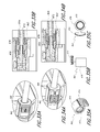
- FIG. 1 is a scaled photograph of an embodiment of a pump assembly that can be used to move fluids.
- FIG. 2 is an isometric view of the pump assembly embodiment illustrated in FIG. 1 , showing a top surface of the pump assembly.
- FIG. 3 is an isometric view of the pump assembly embodiment illustrated in FIG. 1 , showing a bottom surface of the pump assembly.
- FIG. 4 is an exploded view of the pump assembly embodiment illustrated in FIG. 1 .
- FIG. 5 is a section view of the pump assembly embodiment illustrated in FIG. 1 , taken through the axial centerline of the pump assembly embodiment.
- FIG. 6 is an isometric view of the valve support member and the valve plate of the pump assembly embodiment illustrated in FIG. 1 .
- FIG. 7 is an isometric view of a second half or portion of a valve housing that could be formed on the housing, to complete the valve chamber.
- FIG. 8A illustrates one arrangement of a magnetic circuit of the pump assembly embodiment illustrated in FIG. 1 .
- FIG. 8B is an enlarged view of a portion of the arrangement of the magnetic circuit illustrated in FIG. 8A .
- FIG. 9 is an isometric view of another embodiment of a pump assembly, showing a top surface of the pump assembly.
- FIG. 10 is an isometric view of the pump assembly embodiment illustrated in FIG. 9 , showing a bottom surface of the pump assembly.
- FIG. 11 is an exploded view of the pump assembly embodiment illustrated in FIG. 9 , showing the top of the pump assembly.
- FIG. 12 is an exploded view of the pump assembly embodiment illustrated in FIG. 9 , showing the bottom of the pump assembly.
- FIG. 13 is an exploded view of a valve assembly of the pump assembly embodiment illustrated in FIG. 9 , showing the top of the valve assembly.
- FIG. 14 is an exploded view of the valve assembly of the pump assembly embodiment illustrated in FIG. 9 , showing the bottom of the valve assembly.
- FIG. 15 is a section view of the pump assembly embodiment illustrated in FIG. 9 , the section being taken through the center of the pump assembly embodiment.
- FIG. 16 is an illustration of a first drum pump (also referred to herein as a thick pump) that was built for experimental purposes.
- FIG. 17 is a photograph of a second drum pump (also referred to herein as a thin pump) that was built for experimental purposes.
- FIG. 18 shows a an illustration of the experimental test setup used to test the first, thick, and the second, thin, experimental pump assemblies.
- FIGS. 19 and 20 show the measured drive signal and current draw for second thin drum pump for the two cases described in Table 2.
- FIG. 21 shows the instantaneous power draw of the second, thin pump.
- FIG. 22 illustrates the back EMF across the coil of the second, thin pump.
- FIGS. 23-26 illustrate waveforms of various signals for driving a diaphragm.
- FIGS. 27A-27G are an isometric view, a top view, a bottom view, a top end view, a bottom end view, a first side view, and a second side view, respectively, of an embodiment of a pump assembly.
- FIGS. 27H-27I are a side view and an isometric view of the pump assembly embodiment shown in FIG. 27A , respectively, showing a housing of the pump assembly in a partially open position.
- FIG. 28 is an exploded view of a portion of an embodiment of a pump assembly.
- FIG. 29A is an enlarged isometric view of a portion of the embodiment of a pump assembly shown in FIG. 28 , showing a slider member of an embodiment of a conduit connector in a first, open position.
- FIG. 29B is a section view of a portion of the embodiment of a pump assembly shown in FIG. 28 , showing a slider member in the first, open position.
- FIG. 30A is an enlarged isometric view of a portion of the embodiment of a pump assembly shown in FIG. 28 , showing a slider member in a second, closed position.
- FIG. 30B is a section view of a portion of the embodiment of a pump assembly shown in FIG. 28 , showing a slider member in the second, closed position.
- FIGS. 31A, 31B, and 31C are an isometric, side, and end view of an embodiment of a slide member.
- FIG. 32 is an exploded view of a portion of another embodiment of a pump assembly having another embodiment of a conduit connector.
- FIG. 33A is an enlarged isometric view of a portion of the embodiment of a pump assembly shown in FIG. 32 , showing a slider member of an embodiment of a conduit connector in a first, open position.
- FIG. 33B is a section view of a portion of the embodiment of a pump assembly shown in FIG. 32 , showing a slider member in the first, open position.
- FIG. 34A is an enlarged isometric view of a portion of the embodiment of a pump assembly shown in FIG. 32 , showing a slider member in a second, closed position.
- FIG. 34B is a section view of a portion of the embodiment of a pump assembly shown in FIG. 32 , showing a slider member in the second, closed position.
- FIGS. 35A, 35B, and 35C are an isometric, side, and end view of another embodiment of a slide member.
- FIG. 36 is an exploded view of a portion of another embodiment of a pump assembly having another embodiment of a conduit connector.
- FIG. 37A is an enlarged isometric view of a portion of the embodiment of a pump assembly shown in FIG. 36 , showing a slider member of an embodiment of a conduit connector in a first, open position.
- FIG. 37B is a section view of a portion of the embodiment of a pump assembly shown in FIG. 36 , showing a slider member in the first, open position.
- FIG. 38A is an enlarged isometric view of a portion of the embodiment of a pump assembly shown in FIG. 36 , showing a slider member in a second, closed position.
- FIG. 38B is a section view of a portion of the embodiment of a pump assembly shown in FIG. 36 , showing a slider member in the second, closed position.
- FIGS. 39A, 39B, and 39C are an isometric, side, and end view of another embodiment of a slide member.
- FIGS. 40A-40G are an isometric view, a top view, a bottom view, a top end view, a bottom end view, a first side view, and a second side view, respectively, of another embodiment of a pump assembly.
- FIG. 40H is a side view of the pump assembly embodiment shown in
- FIGS. 41A-41G are an isometric view, a top view, a bottom view, a top end view, a bottom end view, a first side view, and a second side view, respectively, of an embodiment of a pump assembly.
- FIGS. 42A-42G are an isometric view, a top view, a bottom view, a top end view, a bottom end view, a first side view, and a second side view, respectively, of another embodiment of a pump assembly.
- FIGS. 43A-43G are an isometric view, a top view, a bottom view, a top end view, a bottom end view, a first side view, and a second side view, respectively, of another embodiment of a pump assembly.
- FIGS. 44A-44G are an isometric view, a top view, a bottom view, a top end view, a bottom end view, a first side view, and a second side view, respectively, of another embodiment of a pump assembly.
- FIGS. 45A-45G are an isometric view, a top view, a bottom view, a top end view, a bottom end view, a first side view, and a second side view, respectively, of another embodiment of a pump assembly.
- FIGS. 46A-46G are an isometric view, a top view, a bottom view, a top end view, a bottom end view, a first side view, and a second side view, respectively, of another embodiment of a pump assembly.
- FIGS. 47A-47G are an isometric view, a top view, a bottom view, a top end view, a bottom end view, a first side view, and a second side view, respectively, of another embodiment of a pump assembly.
- FIGS. 48A-48G are an isometric view, a top view, a bottom view, a top end view, a bottom end view, a first side view, and a second side view, respectively, of another embodiment of a pump assembly.
- FIG. 49 is an isometric view of another embodiment of a pump assembly, showing a top surface of the pump assembly.
- FIG. 50 is an isometric view of the pump assembly embodiment illustrated in FIG. 49 , showing a bottom surface of the pump assembly.
- FIG. 51 is an exploded view of the pump assembly embodiment illustrated in FIG. 49 , showing the top of the pump assembly.
- FIG. 52 is an exploded view of the pump assembly embodiment illustrated in FIG. 49 , showing the bottom of the pump assembly.
- FIG. 53 is a section view of the pump assembly embodiment illustrated in FIG. 49 , the section being taken through the center of the pump assembly embodiment.
- FIGS. 54 and 55 are isometric views of another embodiment of a pump assembly, showing a top surface of the pump assembly and the bottom surface of the pump assembly, respectively.
- FIGS. 56 and 57 are exploded views of the pump assembly embodiment illustrated in FIG. 54 , showing the top of the pump assembly and the bottom of the pump assembly, respectively.
- FIG. 58 is a section view of the pump assembly embodiment illustrated in FIG. 54 , the section being taken through the center of the pump assembly embodiment.
- FIGS. 59 and 60 are a top view and a section view of another embodiment of a pump assembly.
- FIG. 61 is an exploded view of the pump assembly embodiment illustrated in FIG. 59 .
- FIGS. 62 and 63 are isometric views, showing the top and the bottom sides of another embodiment of a pump assembly.
- FIGS. 64 and 65 are exploded views of the pump assembly embodiment illustrated in FIG. 62 .
- FIG. 66 is a section view of the pump assembly embodiment illustrated in FIG. 62 .
- FIGS. 67 and 68 are isometric views of another embodiment of a pump assembly, showing a top surface of the pump assembly and the bottom surface of the pump assembly, respectively.
- FIGS. 69 and 70 are exploded views of the pump assembly embodiment illustrated in FIG. 67 , showing the top of the pump assembly and the bottom of the pump assembly, respectively.
- FIG. 71 is a section view of the pump assembly embodiment illustrated in FIG. 67 , the section being taken through the center of the pump assembly embodiment.
- FIG. 72 is an isometric view of another embodiment of a pump assembly that can be used to provide reduced pressure to a wound dressing.
- FIG. 73 is another isometric view of the embodiment of the pump assembly shown in FIG. 72 .
- FIG. 74 is a front view of the embodiment of the pump assembly shown in FIG. 72 .
- FIG. 75 is a sectional view of the embodiment of the pump assembly the pump assembly shown in FIG. 72 .
- FIG. 76 is an exploded assembly view of the embodiment of the pump assembly shown in FIG. 72 .
- FIG. 77 is an enlarged exploded view of the embodiment of the pump assembly shown in FIG. 72 .
- FIG. 78 is an enlarged exploded view of the embodiment of the pump assembly shown in FIG. 72 .
- FIGS. 79-98 illustrate a variety of indicator lights that can be included with any pump assembly disclosed herein.
- FIG. 99 is an electrical component schematic of an embodiment of a pump assembly.
- FIGS. 100-103 illustrate sinusoidal waveforms for driving a diaphragm according to some embodiments.
- FIG. 104 illustrates position of a diaphragm according to an embodiment of a pump assembly.
- FIG. 105 illustrates another arrangement of a magnetic circuit of the pump assembly embodiment illustrated in FIG. 1 .
- FIG. 106 is enlarged portion of the arrangement of the magnetic circuit of the pump assembly embodiment illustrated in FIG. 1 .
- Embodiments disclosed herein relate to apparatuses and methods of treating a wound with reduced pressure, including pump and wound dressing components and apparatuses.
- the apparatuses and components comprising the wound overlay and packing materials, if any, are sometimes collectively referred to herein as dressings.
- wound is to be broadly construed and encompasses open and closed wounds in which skin is torn, cut or punctured or where trauma causes a contusion, or any other surficial or other conditions or imperfections on the skin of a patient or otherwise that benefit from reduced pressure treatment.
- a wound is thus broadly defined as any damaged region of tissue where fluid may or may not be produced.
- wounds include, but are not limited to, acute wounds, chronic wounds, surgical incisions and other incisions, subacute and dehisced wounds, traumatic wounds, flaps and skin grafts, lacerations, abrasions, contusions, burns, diabetic ulcers, pressure ulcers, stoma, surgical wounds, trauma and venous ulcers or the like.
- the components of the TNP system described herein can be particularly suited for incisional wounds that exude a small amount of wound exudate.
- TNP topical negative pressure
- negative pressure wound therapy assists in the closure and healing of many forms of “hard to heal” wounds by reducing tissue oedema, encouraging blood flow and granular tissue formation, and/or removing excess exudate and can reduce bacterial load (and thus infection risk).
- the therapy allows for less disturbance of a wound leading to more rapid healing.
- TNP therapy systems can also assist in the healing of surgically closed wounds by removing fluid and by helping to stabilize the tissue in the apposed position of closure.
- a further beneficial use of TNP therapy can be found in grafts and flaps where removal of excess fluid is important and close proximity of the graft to tissue is required in order to ensure tissue viability.
- reduced or negative pressure levels represent pressure levels that are below standard atmospheric pressure, which corresponds to 760 mmHg (or 1 atm, 29.93 in Hg, 101.325 kPa, 14.696 psi, etc.).
- a negative pressure value of ⁇ X mmHg reflects absolute pressure that is X mmHg below 760 mmHg or, in other words, an absolute pressure of (760 ⁇ X) mmHg.
- negative pressure that is “less” or “smaller” than X mmHg corresponds to pressure that is closer to atmospheric pressure (e.g., ⁇ 40 mmHg is less than ⁇ 60 mmHg).
- Negative pressure that is “more” or “greater” than ⁇ X mmHg corresponds to pressure that is further from atmospheric pressure (e.g., ⁇ 80 mmHg is more than ⁇ 60 mmHg).
- the negative pressure range for any embodiments of the present disclosure can be approximately ⁇ 80 mmHg, or between about ⁇ 20 mmHg and ⁇ 200 mmHg. Note that these pressures are relative to normal ambient atmospheric pressure thus, ⁇ 200 mmHg would be about 560 mmHg in practical terms.
- the pressure range can be between about ⁇ 40 mmHg and ⁇ 150 mmHg.
- a pressure range of up to ⁇ 75 mmHg, up to ⁇ 80 mmHg or over ⁇ 80 mmHg can be used.
- a pressure range of below ⁇ 75 mmHg can be used.
- a pressure range of over approximately ⁇ 100 mmHg, or even 150 mmHg can be supplied by the negative pressure apparatus.
- Other details regarding the operation of the pump assembly are set forth in U.S. patent application Ser. No. 13/092,042, and such embodiments, configurations, details, and illustrations thereof are hereby incorporated by reference in their entireties as if made part of this disclosure.
- any of the embodiments disclosed herein can comprise a pump and/or a pump and dressing kit.
- the pump apparatuses and embodiments of the present disclosure are not limited to use with a dressing or for wound therapy.
- Any of the pump embodiments disclosed herein can be used independently of the dressing components disclosed herein.
- any of the pump embodiments disclosed herein can be used, or can be adapted for use, for other purposes outside of negative pressure wound therapy.
- any of the pump embodiments disclosed herein can be used, or can be adapted for use, to move fluids (gaseous and/or liquid) in any system or application.
- FIG. 1 is a scaled photograph of an embodiment of a pump assembly 100 that can be used to move fluids.
- FIGS. 2 and 3 are isometric views of the pump assembly embodiment illustrated in FIG. 1 , showing a top surface of the pump assembly and the bottom surface of the pump assembly, respectively.
- FIGS. 4 and 5 are an exploded view and a section view of such pump assembly embodiment, the section view being taken through the axial centerline of the pump assembly embodiment.
- the pump assembly embodiment 100 can have a compact, small size. In any embodiments disclosed herein, the pump assembly embodiment 100 can have a diameter or lateral size in the range of approximately 26 mm to approximately 27 mm, or between approximately 22 mm or smaller and approximately 28 mm. In any embodiments disclosed herein, the pump assembly embodiment 100 can have a thickness or height of approximately 8 mm, or from approximately 6 and approximately 10 mm. The pump assembly embodiment 100 can be any miniaturized size that is manufacturable, and the overall power output and efficiency meet the needed requirements for the desired application, within or outside of wound therapy.
- the pump in some pump assembly embodiments that may be suitable for applications requiring miniaturized pumps, can have a diameter or lateral size of approximately 10 mm or less to approximately 15 mm, and a thickness or height of from approximately 3 mm and approximately 6 mm.
- the sizes and ranges listed herein can apply to any pump embodiment disclosed in this application. Only manufacturing technology limits the lower end of the size scale, although fluid power output and overall efficiency will decrease with decreasing size—but a smaller pump would still be useful in other applications.
- efficiency can be defined as (fluid power out)/(electrical power in). Additionally, as used herein, unless otherwise specified, the term approximately, as applied to measures of length, weight, time, efficiency rates, percentages, and other similar measures, is meant to refer to a range of plus or minus 15% of the stated value.
- This embodiment and arrangement of the pump assembly embodiment can be referred to as a “drum” type pump.
- the pump assembly embodiment 100 can be produced for a low cost and can operate at high efficiencies, making it beneficial for portable, disposable, and/or single use applications.
- This pump can be used in an ultra-portable single-use negative-pressure wound therapy (NPWT) device.
- NGWT negative-pressure wound therapy
- the pump assembly embodiment 100 can run for a week on a small primary cell without the need for battery replacement or recharging. Some embodiments of the pump assembly can run up to a week on a 1200 mAh cell, assuming the pump is working for about 20% of the time.
- Any pump assembly embodiments disclosed herein can be configured to be capable of producing approximately 118 ml/min of fluid displacement for a power draw of 94 mW.
- the drive electronics can include a buck-boost convertor to supply a constant voltage from the battery, and a chip to both control the overall system logic and to generate the drive signal for the voice coil actuator (VCA), some pump embodiments disclosed herein will produce a battery life of approximately 7.04 days from the soft-pack Li/MnO 2 , model CF502445.
- the pump assembly embodiment 100 can be used for negative pressure wound therapy.
- the pump assembly embodiment 100 is not limited to use in NPWT systems.
- the pump assembly embodiment can be adapted and configured for use in any reduced pressure system or in any system or application in which the movement of gaseous and liquid fluids is desired.
- the pump assembly embodiment 100 can be configured as a small diaphragm pump with passive valves (such as, but not limited to, flap valves) that can be driven by a VCA.
- the pump can be designed to work at pressures of 60-80 mm Hg, and can be configured to produce a flow rate of approximately 100 ml min-1, with a minimum efficiency of 15%, in order for the NPWT device to run for a week on a specified battery capacity.
- the pump assembly embodiment 100 can be adapted to operate at efficiency levels in excess of 25%.
- the pump assembly embodiment 100 can have a housing 102 adapted to support and protect many of the components of the pump assembly embodiment 100 .
- An upper pole 104 can be supported at one end (for example, a first end) 102 a of the housing 102 .
- the upper pole 104 can have an opening 106 formed through an axial centerline of the upper pole 104 .
- a bearing 108 can be supported by the upper pole 104 , within the opening 106 .
- the bearing 108 or any other components disclosed in this application can be formed by stereolithography, selective laser sintering, molding, or by other suitable processes.
- Two or more electrical wires 114 can be connected to the pump assembly embodiment 100 , configured to provide power to the pump assembly embodiment 100 .
- the wires 114 can be used to provide electrical current to the coil of the pump assembly.
- the electrical wires 114 can be routed through one or more openings formed in the housing 102 or other components of the pump assembly embodiment 100 .
- the housing 102 can support a valve support member 120 at an end (for example, a second end 102 b ) of the housing 102 .
- the valve support member 120 can support a boss member 122 that can receive a conduit therein or thereover, the boss member 122 having an opening 124 therethrough.
- the opening 124 can be in fluid communication with one or more passageways inside the pump assembly embodiment 100 .
- the valve support member 120 can support one side of two valve chambers 121 , a first inlet valve chamber 121 a and a first outlet valve chamber 121 b , which will be described in greater detail below.
- the valve support member 120 can support a flexible valve plate 126 having two flaps 128 , one per chamber.
- the valve plate 126 can have a first flap 128 a and a second flap 128 b configured to deflect away from the relaxed position of the flaps 128 shown in FIGS. 4-5 .
- the valve plate 126 and flaps 128 can be formed from a silicone rubber.
- valve plate embodiments disclosed in relation to any pump embodiment disclosed herein can be formed, print-cut, or dye cut from silicone sheet material, or cast or molded from silicone or other suitable materials, and can have any of the following shore hardness values: 20A, 40A, 50A, 60A and 80A.
- Any of the valve flaps disclosed herein can have one or more score lines therein to improve flexibility.
- FIG. 6 is an isometric view of the valve support member 120 and the valve plate 126 of the embodiment of the pump assembly embodiment 100 illustrated in FIG. 1 .
- FIG. 7 is an isometric view of a second half or portion of a valve housing that could be formed on the housing 102 , to complete the valve chamber.
- the first inlet valve chamber 121 a of the valve support member 120 can have a cavity or depression 130 and one or more openings, such as opening 124 in communication with the depression 130 to permit the passage of air from a conduit connected to the boss 122 into the pump assembly embodiment 100 when the flap valve 128 a is in an open position (for example, not sealingly covering the opening 124 ).
- a boss 131 can be formed within the depression 130 surrounding the opening 124 to provide a sealing surface for the valve flap 128 to selectively seal the opening 124 .
- the boss 131 can have an angled or curved surface 131 a (as shown in FIG.
- valve flap 128 a configured to substantially match the profile of the valve flap 128 a as the valve flap 128 a is deflected from its relaxed position to a position against the surface of the boss 131 .
- This arrangement can improve the seal between the valve flap 128 a and the boss 131 to increase the efficiency of the pump assembly embodiment 100 .
- the first outlet valve chamber 121 b can have a cavity or depression 132 and one or more openings 134 configured to allow the passage or exit of air from the inside of the depression 132 and the pump assembly embodiment 100 when the valve flap 128 b is in an open position.
- the valve support member 120 has two openings 134 formed in the first outlet valve chamber 121 b.
- the housing 102 can have a similar arrangement of inlet and outlet valve chambers as compared to the first inlet and outlet valve chambers 121 a , 121 b.
- a second inlet valve chamber 141 a supported or defined by the housing 102 can have a cavity or depression 146 and one or more openings 148 in communication with the depression 146 to permit the passage of air from the first inlet valve chamber 121 a into the second inlet valve chamber 146 when the valve flap 128 a is in an open position.
- One or more openings 148 can be formed in the second inlet valve chamber 141 a to permit air to pass from the second inlet valve chamber 146 into the inside of the pump assembly embodiment 100 .
- the inlet valve chamber and/or the outlet valve chamber, on either side of the flap valve can have one, two, three, ore more openings configured to permit air to pass therethrough.
- a second outlet valve chamber 141 b can be supported or defined by the housing 102 .
- the second outlet valve chamber 141 b can have a depression 150 formed therein and an opening 152 in communication with the second outlet valve chamber 141 b .
- a boss 154 can be formed within the depression 150 surrounding the opening 152 to provide a sealing surface for the valve flap 128 b to selectively seal the opening 152 .
- the boss 152 can have an angled or curved surface 154 a configured to substantially match the profile of the valve flap 128 b as the valve flap 128 b is deflected from its relaxed position to a position against the surface of the boss 154 a .
- This arrangement can improve the seal between the valve flap 128 b and the boss 1154 to increase the efficiency of the pump assembly embodiment 100 .
- air or other fluid within the pump assembly embodiment 100 can pass through the opening 152 into the first outlet valve chamber 121 b and exit the pump assembly embodiment 100 through the one or more openings 134 .
- valve flaps 128 a , 128 b can be configured to be unstressed in a neutral position, neither fully open nor fully closed. Therefore, rather than there being a ‘cracking pressure’ required to open them,
- a small back-pressure e.g., approx. 30 mbar or more
- the configuration of the pump assembly embodiment 100 can eliminate or reduce the need for a check valve or other one-way flow restrictor.
- the valve flaps can operate at a frequency in the range of approximately 120 to approximately 150 Hz.
- the pump assembly embodiment 100 can have a coil 160 , a retainer 162 , and a support 164 .
- the support member 164 or any other components disclosed in this application can be formed by stereolithography, selective laser sintering, molding, or by other suitable processes.
- the coil 160 can be formed from a length of wound conductive wire, such as without limitation copper wire or amethyst. In any embodiments disclosed herein, the coil 160 or any coil disclosed herein can be formed by winding approximately 160 turns of wire, or from approximately 100 turns or less to 200 turns or more of wire, which can be but is not required to be, 42 gauge (approximately 0.102 mm diameter) wire.
- the wire used can be self-bonding wire that bonds to adjacent sections of wire upon application of heat.
- the wire can also be non-self-bonding wire.
- approximately 200 turns of wire, or up to approximately 260 turns of wire can be used to form the coil.
- Increasing the number of turns of wire In any embodiments disclosed herein of the pump assembly could reduce ohmic losses and could improve the overall efficiency of the pump by between approximately 22% and approximately 24%.
- the size or thickness of the magnet can be decreased, thereby reducing the magnetic field outside of the pump that can potentially interfere with the function of pacemakers and other implanted cardiac devices (ICDs). It was generally determined during experimentation that increasing the number of turns of wire increased the suction stroke and improved the flow rate of the pump assembly.
- the coil 160 is configured to move within a magnetic circuit, and is connected or supported via the support member 164 to a pump diaphragm assembly 166 .
- the diaphragm 166 can be supported and/or fixed at its outer periphery 166 a , wherein an interior portion 166 b of the diaphragm assembly 166 is permitted to flex and deflect in either direction away from the relaxed position of the diaphragm assembly 166 .
- the diaphragm can be clamped and compressed between two rigid surfaces to provide such support.
- the rigid surfaces can define an annular shape.
- some embodiments of the diaphragm 166 can have a moulding and a separate compression ring (made from a rigid plastic, aluminium or other metal, or any other suitable material or composite material).
- some embodiments of the diaphragm 166 can have one plastic or other frame or moulding on each side of the flexible diaphragm membrane. The mouldings and the flexible diaphragm membrane can be held together with adhesive, mechanical connections between the mouldings, ultrasonically welding, or by any other suitable method.
- the diaphragm can have a single frame or moulding having a channel therein configured to receive and support a peripheral edge of the flexible diaphragm membrane. Additionally, in any embodiments disclosed herein, the diaphragm 166 can be sealed at its outer perimeter 166 a . The diaphragm assembly 166 is configured to elastically return the coil 160 to its relaxed position.
- the configuration of the pump assembly embodiment 100 can be similar to that used in low fidelity loudspeakers, which fit a significant amount of magnetic material into a very compact space.
- the pump assembly embodiment 100 can have a magnet 174 positioned between a lower pole 176 and the upper pole 104 .
- the magnet 174 can be made from sintered Neodymium-Iron-Boron (NdFeB), Neodymium N33, or any other suitable material. This material can be used to maximize field strength and minimize losses, thereby increasing the efficiency of the pump assembly embodiment 100 .
- the magnet 174 can be formed from any suitable magnetic material.
- any of the magnets in any of the embodiments disclosed herein can have any suitable thickness and size, which can depend on the size of one or more of the other components of the pump assembly.
- the magnet 174 can have an approximately 25.65 mm outer diameter, an approximately 15 mm inner diameter, and be approximately 6 mm thick.
- the magnet 174 of some embodiments can have an approximately 25.65 mm outer diameter, an approximately 17 mm inner diameter, and be approximately 3.5 mm thick.
- the thickness of the magnet In any embodiments disclosed herein can be as small as 2.5 mm.
- the upper pole 104 can have a body portion 105 extending away from a planar portion 107 of the upper pole 104 .
- the body portion 105 can extend in an axial direction through an axial opening formed in the coil 160 , the magnet 174 , and the lower pole 176 .
- the body portion can improve the magnetic field of the voice coil actuator and improve the efficiency of the voice coil pump.
- shielding components or materials configured to attenuate the magnetic field outside of the pump assembly can be used.
- materials with very high nickel content for example, from 50-80%
- MuMetal is one material that can be used for this purpose.
- FIG. 8 is a partial cut-away of the an arrangement of a magnetic circuit, with contours of simulated radial magnetic field strength.
- the thin drum prototype described in greater detail below was measured to have a field strength of approximately 0.7 kG at the surface, dropping to 5 G at a distance of around 55 mm, as measured with a Gauss meter. In its current state, therefore, the pump should not be used within this distance from a pacemaker. If this distance can be reduced significantly (to, e.g., under 1 inch), that would be beneficial.
- the arrangement of the pump assembly embodiment 100 can be configured to differ from a typical low fidelity loudspeaker.
- some embodiments of the pump assembly 100 can differ in the following ways.
- the coil 160 can be configured to underhang below the end of the magnetic circuit.
- the coil 160 can be configured such that it does not extend above the magnetic circuit. This can improve the efficiency and reduce the overall height of the pump assembly embodiment 100 , but can result in the degradation of the linearity of response of the pump assembly embodiment 100 .
- the coil 160 can have a relatively high number of turns.
- any coil embodiments disclosed herein including but not limited to coils 160 and 260 (described below), can have approximately 100 or more turns of wire (which can be copper), or less than 100 turns or wire, or between approximately 100 turns and approximately 160 turns of wire. Some embodiments have as can fit into the space left by the magnetic circuit, based on available or practical wire thicknesses. Generally, the electrical efficiency of the pump assembly will be increased as the number of turns is increased.
- the density of the copper can be maximized for the available space, or per unit volume of copper wire in the coil.
- the wire used for the coil can have a round, flat, square, rectangular, or diamond cross-section. The non-circular cross section shaped wire can result in a more dense copper wire packing and higher electrical efficiency.
- Having a relatively high number of turns can give the coil 160 greater structural rigidity and, as mentioned, can maximize the efficiency of the pump assembly embodiment 100 .
- Having a relatively high number of turns in the coil 160 can also limit the frequency of oscillation. The impact of limiting the frequency of oscillation should not affect the performance of the pump assembly embodiment 100 because, In any embodiments disclosed herein, the operating frequency of the pump assembly embodiment 100 can be limited by the responsiveness of the valves, for example, by the responsiveness of the valve flaps 128 a , 128 b.
- the pump assembly embodiment 100 will not have a speaker cone that is typically in a low fidelity speaker, which normally serves to control coil motion.
- the diaphragm can be used to center the coil 160
- a linear bearing 108 can be used to limit any wobble of the coil 160 by controlling the movement of the support member 164 .
- the housing 102 , support 114 , valve support member 120 , retainer 162 , and/or support member 164 can be made of a plastic or hard rubber material, metal, or any other suitable material or combination of materials. Such components can be formed by any suitable methods such as casting, any molding process such as injection molding, forging, sintering, machining, or any other suitable process.
- FIG. 105 illustrates an arrangement of a magnetic circuit 3200 according to some embodiments.
- FIG. 105 is a partial cut-away of the an arrangement of the magnetic circuit 3200 , with contours of simulated radial magnetic field strength (e.g., in Tesla). This arrangement can be similar to the arrangement illustrated in FIG. 8 .
- the circuit 3200 can include a magnet 3202 positioned between a lower pole 3206 and an upper pole 3204 .
- a coil 3208 can be positioned in a groove in which the coil moves.
- the magnetic field can have a north orientation at the bottom of the diagram and a south orientation at the top of the diagram in FIG. 105 . In certain embodiments, these directions can be reversed.
- the upper and lower pole pieces 3204 and 3206 are not symmetrical with respect to the coil 3208 .
- this arrangement of the upper and lower pole pieces can act as a magnetic field “guide” that places the magnetic flux symmetrically with the coil 3208 .
- the magnetic flux is at its strongest in region 3210 as is evidenced by the density of the flux lines in region 3210 . Accordingly, the magnetic field of the magnet 3202 , which would normally be centered around the magnet, is shifted to be aligned with the coil 3208 .
- the entire arrangement illustrated in FIG. 105 contributes to aligning the magnetic field with the coil 3208 .
- the arrangement and/or placement of the upper pole piece 3204 contributes to aligning the magnetic field with the coil 3208 . In any embodiments disclosed herein, such alignment of the magnetic field with the coil 3208 improves efficiency of the voice coil pump.
- FIGS. 9 and 10 are isometric views of another pump assembly embodiment 200 , showing a top surface of the pump assembly and the bottom surface of the pump assembly, respectively.
- FIGS. 11 and 12 are exploded views of the pump assembly embodiment illustrated in FIG. 9 , showing the top of the pump assembly and the bottom of the pump assembly, respectively.
- the pump assembly embodiment 200 can have a compact, small size and can have any of the same features, components, materials, or other details of the pump assembly embodiment 100 described above, or any of the other pump assembly embodiments disclosed herein.
- the pump assembly embodiment 200 can have a diameter or lateral size in the range of approximately 26-29 mm, or between approximately 25 and approximately 28 mm. In any embodiments disclosed herein, the pump assembly embodiment 200 can have a thickness or height of approximately 8 mm, or between approximately 6 mm and approximately 10 mm. Similar to the pump assembly embodiment 100 above, this embodiment and arrangement of the pump assembly embodiment can also be referred to as a “drum” type pump.
- the pump assembly embodiment 200 can be produced for a low cost and can operate at high efficiencies, making it beneficial for portable, disposable, and/or single use applications. In any embodiments disclosed herein, the pump assembly embodiment 200 can run for a week on a small primary cell without the need for battery replacement or recharging. This pump can be used in an ultra-portable single-use negative-pressure wound therapy (NPWT) device, but is not so limited. In any embodiments disclosed herein, as mentioned, the pump assembly embodiment 200 can be used for negative pressure wound therapy. However, the pump assembly embodiment 200 is not limited to use in negative pressure wound therapy systems. The pump assembly embodiment can be adapted and configured for use in any reduced pressure system or in any system or application in which the movement of gaseous and liquid fluids is desired.
- NGWT ultra-portable single-use negative-pressure wound therapy
- the pump assembly embodiment 200 can be designed to work at pressures of 60-80 mm Hg, and can be configured to produce a flow rate of approximately 200 ml min-1, with a minimum efficiency of 15%, in order for the NPWT device to run for a week on a specified battery capacity. In any embodiments disclosed herein, the pump assembly embodiment 200 can be adapted to operate at efficiency levels in excess of 25%.
- the pump assembly embodiment 200 can have a housing 202 adapted to support and protect many of the components of the pump assembly embodiment 200 .
- An upper pole 204 which can be made from any suitable materials such as mild steel or sintered steel, can be supported at one end (for example, a first end) 202 a of the housing 202 .
- the upper pole 204 can have an opening 206 formed through an axial centerline of the upper pole 204 .
- a bearing 208 can be supported by the upper pole 204 , within the opening 206 .
- Two or more electrical wires 214 can be connected to the pump assembly embodiment 200 , configured to provide power to the pump assembly embodiment 200 .
- the wires 214 can be used to provide electrical current to the coil 260 of the pump assembly.
- the electrical wires 214 can be routed through one or more openings or channels formed in the housing 202 , such as channels 215 shown in FIG. 12 .
- a cover 216 can be positioned over the electrical wires 214 after the electrical wires have been advanced through the channels 215 .
- the cover 216 can be an adhesive backed foil, film, paper, plastic sheet or label, or other similar object.
- An opening 217 can be formed in the cover 216 to permit air, gas, or other fluid to be exhausted from the pump through the outlet manifold.
- the cover 216 can be configured to complete the inlet vacuum channel. In other words, the cover 216 can be configured to separate or seal the vacuum created by the pump from atmosphere. Using a thin label in place of a thicker plastic molded part or otherwise can decrease the height or thickness of the pump as much as possible. Alternatively, some embodiments of the pump assembly can have a thicker cover that can be molded, cast, machined, or formed by any other suitable method.
- the housing 202 can support a valve assembly 220 at an end (for example, a second end 202 b ) of the housing 202 .
- the housing 202 can support a boss member 222 that can receive a conduit therein or thereover, the boss member 222 having an opening 224 therethrough.
- the opening 224 can be in fluid communication with one or more passageways inside the pump assembly embodiment 200 , such as air passageway 203 formed (that can be covered by the cover 216 ) in the housing 202 that communicates with the air passageway 229 formed in the valve assembly 220 .
- FIGS. 13 and 14 are exploded views of the valve assembly of the pump assembly embodiment 200 illustrated in FIG. 9 , showing the top of the valve assembly and the bottom of the valve assembly, respectively.
- FIG. 15 is a section view of the pump assembly embodiment 200 illustrated in FIG. 9 , the section being taken through the center of the pump assembly embodiment 200 .
- the valve assembly 220 can have a first valve member 225 , a second valve member 227 , and a valve plate 226 .
- the valve plate 226 can support two flexible valve flaps 228 , a first valve flap 228 a for the inlet valve chamber and a second valve flap 228 b for the outlet valve chamber.
- the first flap 228 a and the second flap 228 b can be configured to deflect away from the relaxed position of the flaps 228 shown in FIGS. 4-5 .
- the first inlet valve chamber 221 a of the second valve member 227 can have a cavity or depression 230 and one or more openings, such as opening 224 in communication with the depression 230 to permit the passage of air from the channel 229 into the pump assembly embodiment 200 when the flap valve 228 a is in an open position.
- a boss 231 can be formed within the depression 230 surrounding the opening 224 to provide a sealing surface for the valve flap 228 to selectively seal the opening 224 .
- the boss 231 can have an angled or curved surface 231 a (as shown in FIG. 5 ) configured to substantially match the profile of the valve flap 228 a as the valve flap 228 a is deflected from the relaxed position against the surface of the boss 231 . This arrangement can improve the seal between the valve flap 228 a and the boss 231 to increase the efficiency of the pump assembly embodiment 200 .
- the coil (which can be fixed to the support member and the diaphragm) can oscillate up and down in the pump between the two poles.
- the oscillation of the diaphragm can cause the volume within the pump to increase or decrease and, hence, cause the pressure within the pump to decrease or increase.
- a pressure decrease within the pump chamber can draw air into the pump chamber and open the inlet manifold (or flap), while the flap on the outlet manifold can seal the outlet manifold closed. Then, as the diaphragm returns toward the valve support, the volume of airspace decreases, causing the air pressure to increase. This forces air out of the chamber through the outlet valve, while the inlet valve is sealed closed.
- the first outlet valve chamber 221 b of the second valve member 227 can have a cavity or depression 232 and one or more openings 234 configured to allow the passage or exit of air from the inside of the depression 232 and the pump assembly embodiment 200 when the valve flap 228 b is in an open position.
- the valve assembly 220 has three openings 234 formed in the first outlet valve chamber 221 b .
- the housing 202 can have a similar arrangement of inlet and outlet valve chambers as compared to the first inlet and outlet valve chambers 221 a , 221 b.
- a second inlet valve chamber 241 a supported by the first valve member 225 can have a cavity or depression 246 and one or more openings 248 in communication with the depression 246 to permit the passage of air from the first inlet valve chamber 221 a into the second inlet valve chamber 246 when the valve flap 228 a is in an open position (e.g., not sealingly covering the opening 224 ).
- One or more openings 248 can be formed in the second inlet valve chamber 241 a to permit air to pass from the second inlet valve chamber 246 into the inside of the pump assembly embodiment 200 .
- the inlet valve chamber and/or the outlet valve chamber, on either side of the flap valve can have one, two, three, ore more openings configured to permit air to pass therethrough.
- a second outlet valve chamber 241 b can be supported by first valve member 225 .
- the second outlet valve chamber 241 b can have a depression 250 formed therein and an opening 252 in communication with the second outlet valve chamber 241 b .
- a boss 254 can be formed within the depression 250 surrounding the opening 252 to provide a sealing surface for the valve flap 228 b to selectively seal the opening 252 .
- the boss 252 can have an angled or curved surface 254 a configured to substantially match the profile of the valve flap 228 b as the valve flap 228 b is deflected from the relaxed position against the surface of the boss 254 a .
- This arrangement can improve the seal between the valve flap 228 b and the boss 254 to increase the efficiency of the pump assembly embodiment 200 .
- air or other fluid within the pump assembly embodiment 200 can pass through the opening 252 into the first outlet valve chamber 221 b and exit the pump assembly embodiment 200 through the one or more openings 234 .
- valve flaps 228 a , 228 b can be configured to be unstressed in a neutral position, neither fully open nor fully closed. Therefore, rather than there being a ‘cracking pressure’ required to open them,
- a small back-pressure (for example, approx. 30 mbar or more) can be used to hold valve flaps 228 a , 228 b closed. This improves efficiency by reducing the pressure force that must be generated by the VCA during the suction stroke.
- the pump assembly embodiment 200 can have a coil 260 comprising electrical wires 261 , a retainer 264 , and a support 264 .
- the coil 260 can be formed from a length of wound conductive wire, such as without limitation copper wire.
- the coil 260 is configured to move within a magnetic circuit, and is connected or supported via the support member 264 to a pump diaphragm assembly 266 .
- an opening 265 formed in the support member 264 can be configured to receive a boss or protrusion 267 of the diaphragm assembly 266 so the pump diaphragm assembly 266 can be coupled with the support member 264 .
- the diaphragm 266 can be supported and fixed at its outer periphery 266 a , wherein an interior portion 266 b of the diaphragm assembly 266 is permitted to flex and deflect in either direction away from the relaxed position of the diaphragm assembly 266 .
- the diaphragm assembly 266 is configured to elastically return the coil 260 to its relaxed position.
- the diaphragm 266 can be supported and/or fixed along all or a portion of its outer periphery 266 a , wherein an interior portion 266 b of the diaphragm assembly 266 is permitted to flex and deflect in either direction away from the relaxed position of the diaphragm assembly 266 .
- the diaphragm can be clamped and compressed between two rigid surfaces to provide such support.
- the rigid surfaces can define an annular shape.
- some embodiments of the diaphragm 266 (or any other diaphragm disclosed herein) can have a moulding and a separate compression ring (made from a rigid plastic, aluminium or other metal, or any other suitable material or composite material).
- the diaphragm 266 (or any other diaphragm disclosed herein) can have one plastic or other frame or moulding on each side of the flexible diaphragm membrane.
- the mouldings and the flexible diaphragm membrane can be held together with adhesive, mechanical connections between the mouldings, ultrasonically welding, or by any other suitable method.
- the diaphragm can have a single frame or moulding having a channel therein configured to receive and support a peripheral edge of the flexible diaphragm membrane.
- the diaphragm 266 can be sealed at its outer perimeter 266 a .
- the diaphragm assembly 266 is configured to elastically return the coil 160 to its relaxed position.
- any of the pump embodiments disclosed herein can be formed from cast or molded silicone, polyurethane, thermoplastic polyurethane, and/or other suitable materials, having a hardness value of approximately 20A, 30A, 40A, 50A, 55A, or more.
- the pump assembly embodiment 200 can be similar to that used in low fidelity loudspeakers, which fit a significant amount of magnetic material into a very compact space.
- the pump assembly embodiment 200 can have a magnet 274 positioned between a lower pole 276 and the upper pole 204 .
- the magnet 274 can be made from sintered Neodymium-Iron-Boron (NdFeB). This material can be used to maximize field strength and minimize losses, thereby increasing the efficiency of the pump assembly embodiment 200 .
- the magnet 274 can be formed from any suitable magnetic material.
- the lower pole can be approximately 1.5-2.0 mm thick and can be made from any suitable material, such as mild steel.
- FIG. 8 is a cut-away of an arrangement of a magnetic circuit, with contours of simulated radial magnetic field strength.
- the arrangement of the pump assembly embodiment 200 can be configured to differ from a typical low fidelity loudspeaker.
- some embodiments of the pump assembly 200 can differ in the following ways.
- the coil 260 can be configured to underhang below the end of the magnetic circuit.
- the coil 260 can be configured such that it does not extend above the magnetic circuit. This can improve the efficiency and reduce the overall height of the pea 200 , but can result in the degradation of the linearity of response of the pump assembly embodiment 200 .
- the coil 260 can have a relatively high number of turns. Having a relatively high number of turns can give the coil 260 greater structural rigidity and can maximize the efficiency of the pump assembly embodiment 200 . Additionally, the pump assembly embodiment 200 will not have a speaker cone that is typically in a low fidelity speaker, which normally serves to control coil motion. In the pump assembly embodiment 200 , the diaphragm can be used to center the coil 260 , and a linear bearing 208 can be used to limit any wobble of the coil 260 by engaging the protrusion 267 and controlling the movement of the support member 264 .
- the housing 202 , support 214 , valve assembly 220 , retainer 262 , and/or support member 264 can be made of a plastic or hard rubber material, metal, or any other suitable material or combination of materials. Such components can be formed by any suitable methods such as casting, any molding process such as injection molding, forging, sintering, machining, or any other suitable process.
- the pump assembly can be of a sufficiently small and portable size to be supported on a user's body or in a user's clothing.
- any of the pump assemblies disclosed herein can be sized to be attached using adhesive medical tape or otherwise to a person's skin or to a dressing in a comfortable location, adjacent to or on the dressing or otherwise.
- any of the pump assembly embodiments disclosed herein can be sized to fit within a person's pants or shirt pocket, or can be tethered to a person's body using a lanyard, pouch, or other suitable device or article.
- the pump assembly can be powered by one or more batteries (for example, two batteries, or as described in any other embodiments described herein) and can weigh less than 80 grams, including the weight of the batteries.
- the pump assembly can have any desired number of batteries and can weigh from approximately 70 grams to approximately 90 grams, or from approximately 75 grams to approximately 100 grams, or between any values within the foregoing ranges.
- the weight and/or size of the pump assembly could be reduced by reducing the battery size and/or weight (to, for example, AAA sized batteries, or smaller) or the pump size and/or weight.
- Any embodiments of the pump assembly can be powered by any suitable electrical source, including a main supply of electricity.
- any of the pump assemblies described herein can have a layer of open foam or other material wrapped at least partially around an outside surface of the pump to reduce the noise and/or vibration produced by the pump.
- One or more labels can be affixed to an outside surface of the housing of any pump assembly disclosed herein, not only to seal the internal components, but also to recite printed information.
- the pump can have one or more weights, cushions, foam (such as a viscoelastic foam), plastic (such as ABS, polyurethane, urethane, or otherwise), or other pads, panels, sheets, or segments supported by the pump or positioned adjacent to one or more outside surfaces of the pump.
- Any embodiments can have mass based or compliant damping materials. Such components or materials (not illustrated) can damp vibration and/or attenuate noise produced by the pump.
- the pump assemblies disclosed herein can have a flow manifold and a one-way flow valve in communication with a fluid flow pathway within the pump assembly.
- the one-way flow valve (also referred to as a check valve) can be a diaphragm valve made from silicone or any other suitable elastomeric or soft material, including without limitation, polyurethane, viton, nitrile rubber, neoprene, Teflon, and other suitable materials.
- Other suitable valves for the one-way flow valve are, for example and without limitation, umbrella valves, ball valves, reed valves, duckbill valves.
- the leakage rate of the one-way flow valve can be approximately 0.05 mL/minute or less.
- the one-way flow valve can be positioned within the pump assembly or in place of one of the valves positioned within the pump assembly.
- the batteries can be lithium chloride or any other suitable batteries that are suitable for exposure to ethylene dioxide and/or other sterilization gases.
- the batteries can be supported outside of the pump housing so as to minimize or eliminate the chance of an electrical spark which could cause an explosion in the presence of the sterilization gas or an explosive gas during the sterilization process when supported in the packaging element or elements. Additionally, where there are a plurality of batteries, the batteries can be spaced apart or otherwise separated in the packaging to prevent any power loss or sparking of the batteries during the sterilization process or otherwise before usage.
- any embodiments of the dressings disclosed herein can be configured to have a film having a high water vapour permeability to enable the evaporation of surplus fluid, and can have a superabsorbing material contained therein to safely absorb wound exudate.
- Some embodiments of the apparatus are designed for single-use therapy and can be disposed of in an environmentally friendly manner after an approximately maximum usage of from seven to eleven days.
- the pump can be programmed to automatically terminate therapy after a desired number of days, e.g., after seven days, further operation of the pump will not be possible.
- Some embodiments are designed for longer or repeated usage, and can be configured to support an exudate canister.
- a lower surface of any of the wound dressing embodiments for use with the pump assembly disclosed herein can have an optional wound contact layer.
- Any of the dressing embodiments disclosed herein can be made without the wound contact layer.
- the wound contact layer can be a polyurethane layer or polyethylene layer or other flexible layer which can be made porous or perforated, for example via a hot pin process, laser ablation process, ultrasound process or in some other way or otherwise made permeable to liquid and gas. The perforations can enable fluid and/or gas to flow through the layer.
- the wound contact layer can help prevent tissue ingrowth into the other material of the wound dressing.
- any dressing embodiments for use in the dressing kits disclosed or incorporated by reference herein can have an adhesive covered bottom (e.g., wound contacting) surface.
- the adhesive can be a silicone adhesive including, for example, polysiloxanes or polyorganosiloxanes or other polymeric pressure sensitive silicone adhesives.
- polysiloxanes or polyorganosiloxanes or other polymeric pressure sensitive silicone adhesives for example, polydimethylsiloxane or the like can be used.
- the adhesive formulation may be a mixture of alkyl pendant siloxanes, which can be spread and cast as a two part mix with a catalyst such that a final polymerisation step takes place following casting or spreading.
- a dressing layer can have a non-perforated silicone adhesive coating (coat weight 130 gsm nominal) and full spread acrylic adhesive (27 to 37 gsm) coated onto opposite sides of an extruded EU30 polyurethane clear film (27 to 37 gsm).
- Moisture vapour permeability of some embodiments of such an arrangement can be between approximately 367 gm ⁇ 2 /24 hrs to approximately 405 gm ⁇ 2 /24 hrs, or a mean moisture vapour permeability of 382 gm ⁇ 2 /24 hrs.
- any of the dressing embodiments disclosed herein can have an anti-microbial agent or substance incorporated into the dressing or coated on one or more surfaces of the dressing.
- a wound contact layer of any dressing embodiments disclosed herein can have nanocrystalline silver agents, silver salts, copper salts, or gold salts such as, without limitation, those disclosed in U.S. patent application Ser. No. 11/922,894 (titled ANTIMICROBIAL BIGUANIDE METAL COMPLEXES), filed May 21, 2008, which application is incorporated by reference herein as if made part of this disclosure, PHMB, chlorohexadine, peroxide, hypochloride, or other bleaches therein or thereon.
- an absorbent layer of any dressing embodiments disclosed herein can have silver sulphur diazine or any of the previously mentioned substances or active agents therein or thereon. These may be used separately or together. These respectively can eliminate micro-organisms in the wound and micro-organisms in the absorption matrix.
- other active components for example, pain suppressants such as ibuprofen or healing agents can be incorporated into the dressing.
- agents which enhance cell activity such as growth factors or that inhibit enzymes, such as matrix metalloproteinase inhibitors, such as tissue inhibitors of metalloproteinase (TIMPS) or zinc chelators, can be incorporated into the dressing.
- Odor trapping elements such as activated carbon, cyclodextrine, zeolite or the like can also be included in the absorbent layer or other portions or components of the dressing, or above the filter layer.
- any embodiments of the wound therapy apparatuses disclosed herein can be manufactured in a wide variety of different models or versions, wherein the size of the dressing can be varied to accommodate a wide range of wound sizes.
- any of the embodiments disclosed herein can have any of the following sizes of dressings and wound pads or other absorbent elements.
- Approximate Dressing Size Approximate Wound Pad Size 10 cm ⁇ 30 cm (4 in ⁇ 11.75 in) 5 cm ⁇ 20 cm (2 in ⁇ 8 in) 15 cm ⁇ 15 cm (6 in ⁇ 6 in) 10 cm ⁇ 10 cm (4 in ⁇ 4 in) 15 cm ⁇ 20 cm (6 in ⁇ 8 in) 10 cm ⁇ 15 cm (4 in ⁇ 6 in) 10 cm ⁇ 20 cm (4 in ⁇ 8 in) 5 cm ⁇ 10 cm (2 in ⁇ 4 in) 20 cm ⁇ 20 cm (8 in ⁇ 8 in) 15 cm ⁇ 15 cm (6 in ⁇ 6 in)
- the wound site may be filled partially or completely with a wound packing material.
- This wound packing material is optional, but may be desirable in certain wounds, for example deeper wounds.
- the wound packing material can be used in addition to the other components of overlay or overlay kit.
- the wound packing material generally can comprise a porous and conformable material, for example foam (including reticulated foams), and gauze.
- the wound packing material is sized or shaped to fit within the wound site so as to fill any empty spaces.
- the wound dressing can then be placed over the wound site and wound packing material overlying the wound site.
- TNP When a wound packing material is used, once the wound dressing is sealed over the wound site, TNP can be transmitted from a pump through or under the wound dressing, through the wound packing material, and to the wound site. This negative pressure draws wound exudate and other fluids or secretions away from the wound site.
- Some embodiments of the overlay or dressing can be substantially impervious to air flow and the flow of bacteria or other contaminants through the overlay layer, while being pervious to vapor transmission.
- any embodiments of the pump and dressing embodiments disclosed herein can be configured or adapted for sterilization before delivery to the hospital, operating room or theatre, or to the medical practitioner using such devices such that the sterile pump and/or a sterile pump/dressing kit can be applied immediately following the surgical or operating procedures.
- One advantage of this is that the surgeon can release the patient from the operating room knowing that the reduced pressure pump is operating and that the reduced pressure therapy has been started at the earliest point in time possible.
- a further advantage of applying the dressing kit immediately following the surgical or other procedure is that doing so can reduce the chance of infection by eliminating a subsequent dressing change that may otherwise be required in the ward.
- any issues with the dressing that may require the dressing to be removed, repositioned, or otherwise, can be handled in the sterile operating room environment, thereby significantly reducing or eliminating the risk of exposure to pathogens, bacteria, or other contaminants.
- any of the pump assembly embodiments disclosed herein can be configured to be amenable to gas sterilization, having features, components, and other characteristics that make the pump amenable to full sterilization gas exposure and penetration throughout the components of the pump.
- one or more pump valves or flap valves can be selected or configured to permit a sufficient flow of sterilization gas therethrough such that the entire fluid pathway within the pump can be exposed to the sterilization gas.
- the pump can have other components, such as without limitation, strategically positioned one way flow valves, to complement the other valves within the pump, which can improve the efficiency of the pump by reducing leakage through the flow pathway within the pump assembly.
- the sterile pump/dressing kit can also be designed and configured to be amenable to gas sterilization.
- the sterile pump/dressing kit can be configured such that all of the components comprising the sterile pump/dressing kit, including the pump assembly, are packaged together in at least a first packaging element before sterilization, permitting all of the components to be sterilized together.
- the components comprising the sterile pump/dressing kit can be arranged in the packaging such that at least some of the components can be removed in a predefined order, making it easier for the surgeon or medical practitioner to assemble and apply the dressing to the patient.
- the pump assembly can be configured such that a sterilization gas, such as ethylene dioxide, can penetrate into the housing of the pump assembly such that the internal components of the pump assembly are exposed to the sterilization gas during normal sterilization processes.
- a sterilization gas such as ethylene dioxide
- the pump will be exposed to the sterilization gas in a chamber that has been substantially evacuated of air or any other gas, so that the sterilization gas is drawn into the pump housing and into the other spaces and chambers within the pump assembly.
- embodiments disclosed or incorporated by reference herein such as those disclosed in U.S. patent application Ser. No. 13/287, U.S. patent application Ser. No. 13/092,042, Great Britain Patent Application Nos. 1015656.0, 1006986.2, 1006983.9, 1006985.4, 1006988.8, and 1008347.5 comprise improved wound dressing components. All embodiments, components, features, and other details of such disclosures are hereby incorporated by reference herein as if made part of this disclosure, and can be used in place of or in combination with any of the components, features, and other details of the embodiments disclosed herein.
- the wound dressing can be configured to act as a buffer to help prevent compression or shear forces exerted on the wound dressing, for example due to patient movement, from harming a healing wound.
- Embodiments of the wound dressing may act as a waste canister to collect and store wound exudate removed from a wound site, and also relate to the management of solid build-up in a wound dressing covering a wound site whilst TNP therapy is applied. Further, embodiments disclosed herein relate to a method and suction port for applying negative pressure to a wound dressing and a method of manufacturing a suction port and wound dressing.
- a negative pressure therapy apparatus comprises a pump assembly configured to, inter alia, provide negative pressure to a wound.
- Some embodiments of pump assemblies disclosed herein comprise novel and inventive control logic configured to control the operation of the pump assembly.
- Any embodiments of the drum pumps disclosed herein can be configured such that their maximum pressure level produced by the pumps is less than the threshold value that is capable of injuring a user.
- some drum pump embodiments disclosed herein can be configured so that it is impossible for the drum pump to produce vacuum levels that can harm a user.
- control logic configured to control the operation of a pump assembly in response to monitoring and detecting various operating conditions, such as presence and/or severity of a leak or leaks in the system, rate of flow of fluid (e.g., air, liquid and/or solid exudate, etc.) aspirated from a wound, and the like.
- the control logic can be configured to detect a leak or leaks in a system (e.g., leak or leaks in the dressing that is in fluid communication with the pump, leak or leaks in the seal created by the dressing over the wound, etc.) as well as to control the operation of the pump assembly when such leak or leaks are detected.
- the pump assembly can be configured to distinguish between at least a normal or low leak (e.g., a leak that has a relatively low flow rate), a high leak (e.g., a leak that has a relatively high flow rate), and a very high leak (e.g., a leak that has a relatively very high flow rate).
- a normal or low leak e.g., a leak that has a relatively low flow rate
- a high leak e.g., a leak that has a relatively high flow rate
- a very high leak e.g., a leak that has a relatively very high flow rate
- the pump assembly can comprise a source of negative pressure, such as a miniature, disposable pump, powered by a power source, such as a battery source.
- the pump assembly can be configured to provide therapy for a predetermined period of time, such as approximately 1 day, 2-10 days, etc. In any embodiments disclosed herein, the pump assembly can be required to provide uninterrupted therapy for such period of time. In any embodiments disclosed herein, the pump assembly can be configured to deactivate itself a predetermined period of time (e.g., 7 days) after an initial activation.
- the algorithms or logic disclosed herein can help the pump assembly operate more efficiently and conserve power, for example but without limitation, battery power.
- the system can be configured to provide “play/pause” functionality and/or logic via a switch, button, etc. located on the exterior of the pump assembly's housing or any other suitable place where it can be accessed by the user.
- Play/pause functionality can allow the user to suspend and/or restart therapy (e.g., pause and/or restart the pump).
- the pump assembly can be configured to automatically restart therapy following a certain predetermined or variable pause interval.
- the pump assembly can be configured to automatically restart therapy upon expiration of such interval and/or indicate to the user expiration of such interval.
- the system can be configured to provide indication, alarms, etc. to the user reflecting operating conditions.
- the system can include visual, audible, tactile, and other types of indicators and/or alarms configured to signal to the user various operating conditions. Such conditions include system on/off, standby, pause, normal operation, dressing problem, leak, error, and the like.
- the indicators and/or alarms can include speakers (including a speaker made using some or all of the relevant components of the pump motor), displays, light sources, etc., and/or combinations thereof.
- indication can be provided by activating or deactivating the source of negative pressure, reducing negative pressure level generated by the source of negative, lowering the amount of power used by the source of negative pressure, etc. or any combination thereof.
- the pump itself can be used to create audio alarm sounds, buzzing sensations, pulsing sensations, etc.
- the pump assembly can be a canisterless pump assembly (meaning that the pump assembly does not have an exudate or liquid collection canister).
- any of the pump embodiments disclosed herein can be configured to include or support a canister.
- any of the pump assembly embodiments can be mounted to or supported by the dressing, or adjacent to the dressing. The dressing may be placed over a wound (not illustrated) as described in greater detail in U.S. patent application Ser. No. 13/092,042, which disclosure is hereby incorporated by reference and made part of this disclosure, and a conduit may then be connected to the dressing.
- Any dressing disclosed herein can have any of the materials, sizes, components, or other details of any of the dressing embodiments disclosed in U.S. patent application Ser. No. 13/092,042, and such embodiments and illustrations thereof are hereby incorporated by reference in their entireties as if made part of this disclosure.
- the conduit or any other conduit disclosed herein can be formed from polyurethane, PVC, nylon, polyethylene, silicone, or any other suitable material.
- FIG. 16 Two examples of voice coil pump assemblies were constructed and tested.
- a thicker drum pump assembly 300 as illustrated in FIG. 16 , was constructed. This assembly used an off-the-shelf, 25.65 mm outer diameter, 15 mm inner diameter, 6 mm high NdFeB ring magnet. The pump did not fit inside this ring, so the pump head with diaphragm and valves were separated out of the housing and separate from the magnet for this experimental setup.
- a thin drum style pump such as the embodiment of the drum pump 320 as illustrated in FIG. 17 , was constructed.
- the embodiment of the thin drum pump 320 comprises NdFeB magnets ground down to the target size.
- the magnets were machined using a combination of grinding and wire erosion.
- the pole pieces were machined from mild steel, which has a high magnetic saturation. For this application, saturation is more important than permeability, and eddy currents are not an issue. Therefore, typical transformer steels may not be suitable or optimized for the pump embodiments disclosed herein.
- valve chambers were machined from aluminum.
- Machined aluminum has a poor surface finish compared with typical high-volume injection-molded plastic parts.
- the poor surface finished of the aluminum parts may negatively affect the sealing performance and capabilities of the valves if not properly controlled.
- the valve chambers of any of the pump embodiments disclosed herein, such as those of pump assembly embodiments 100 or 200 can be made from injection molded plastic to improve the efficiency of the pumps.
- tolerances of machining are high compared with the total valve flap travel (which, in the constructed examples, was approximately 0.25 mm).
- the machined features can also deviate slightly from the ideal design for reasons of machinability.
- valve plate and diaphragm of the example pumps can be made from cast elastomers, using machined aluminum molds. Again, this may also negatively affect the surface finish of the valve flaps.
- Valve flaps in both silicone and polyurethane were tested, with a range of shore hardness values: 20A, 40A, 60A and 80A. Diaphragms were tested in both 30A and 40A silicone.
- FIG. 18 shows a schematic of the experimental test setup 348 used to test the thick experimental pump assembly embodiment 300 and the thin experimental pump assembly embodiment.
- a graduated cylinder 350 was used as a reservoir of air at constant pressure.
- Tubing 352 runs from the top of the cylinder to a water reservoir 354 , and as air is drawn from the graduated cylinder 350 , so water is drawn up the tubing 353 to replace it.
- the constant head of water maintains the pressure within the cylinder at 80 mm Hg below atmospheric pressure (approximately 10% vacuum).
- the air is drawn through a TSI 4140 flow meter 356 (a thermal-mass flow meter).
- This flow meter 356 has an accuracy of ⁇ 5 sccm (standard cubic centimeters per minute) for flows of 10-250 sccm.
- the flow rate can be independently verified by measuring the rate at which water flows into the graduated cylinder, with an accuracy of ⁇ 4% (assuming flows around 100 ml min ⁇ 1 , measured over approximately 1 minute). Pressure is determined by the head of water.
- a calibrated manometer 358 and also with a pressure meter built into the TSI 4140 flow meter.
- the tubing used is 6 mm ID except for the final section from manometer to pump, which is 2.5 mm ID. At the flow rates observed, and over the tubing lengths used, this does not give any significant pressure loss.
- the VCA 359 is driven from a signal generator 360 .
- the signal generator output is fed to an oscilloscope 362 , monitoring the driving voltage, and a current clamp 364 monitors the current fed to the VCA 359 .
- This data is logged by computer, which multiplies the two signals to determine instantaneous power draw, and averages the power draw over 2.5 seconds (250-500 cycles, for frequencies of 100 Hz-200 Hz, the frequencies used in testing).
- the drive signal in any pump embodiments disclosed herein, including those disclosed below, can be offset to increase the power of the stroke in one direction more than the other.
- the amount of force required to move the diaphragm in an air intake direction is greater than the amount of force required to move the diaphragm in an air offtake or outflow direction. Therefore, the voltage of the drive signal can be offset to supply more power to the motor during the intake portion of the stroke than the offtake portion of the stroke.
- any of the pump embodiments can be configured such that the diaphragm or one or more springs (elastomeric, plastic, metallic, or otherwise) bias the diaphragm in one direction more than another, for example, more in the intake direction than the outflow direction such that the pump can operate at optimal efficiency with a symmetrical drive signal (i.e., a non-offset drive signal).
- a symmetrical drive signal i.e., a non-offset drive signal
- a 40 A valve plate was more tolerant of imperfections in valve housing geometry, but does not respond so quickly, and is therefore less efficient than the 60A valve when the geometry is close enough to design. Note that the prototype valve housings were aluminium machinings, whose dimensions and surface finish are poorly controlled relative to the plastic mouldings envisaged for full production.
- the 20A valve plate did not respond quickly enough to produce a reasonable flow, and the 80A valve plate was too stiff for the valves to operate at all.
- Peak efficiencies achieved were 28.4%, for a flow rate of 60 ml min ⁇ 1 at the target pressure. Peak flow rate at the target pressure was 105 ml min ⁇ 1 , at an efficiency of 24.1%.
- Peak efficiency Peak flow rate Pressure/mm Hg 78.8 78.8 Driving signal waveform Offset sine Offset square Frequency/Hz 120 120 Peak +ve voltage 2.7 3.0 Peak ⁇ ve voltage 1.3 1.0 Power draw/mW 37 76 Diaphragm material 30 shore A silicone 30 shore A silicone Valve material 60 shore A PU 60 shore A PU Flow rate/ml min ⁇ 1 60 105 Efficiency 28.4% 24.1% Flow rate per power drawn/ml 1.62 1.38 min ⁇ 1 mW ⁇ 1
- Peak efficiencies achieved were 22.3%, for a flow rate of 118 ml min ⁇ 1 at the target pressure.
- Peak flow rate at the target pressure was 137 ml min ⁇ 1 , at an efficiency of 22.3%.
- FIGS. 19 and 20 show the measured drive signal and current draw for the second, thin drum pump for the two cases described in Table 2.
- FIG. 21 shows the instantaneous power draw of the second, thin pump, which peaks at 320 mW for the sine signal. Note that one half of the signal contains almost all of the power draw (225 mW vs 50 mW, for the square wave signal): this is the ‘suction’ stroke. Expelling the air to atmosphere requires very little power.
- any of the voice coil actuated pump embodiments disclosed herein can be driven by a signal generator.
- any of the voice coil actuated pump embodiments disclosed herein can be driven by an offset square wave (for example, +3.0 V/ ⁇ 1.0 V), a square wave with a non-50-% duty cycle, an offset sine wave, a symmetric sine wave, a pulsed wave having pulses in either direction (e.g. 35% at +3.0V, 15% rest, 15% ⁇ 3.0V, 35% rest), pulses in either direction with ‘suck’ pulse more than half the cycle (e.g. 75% at +3.0V, 25% ⁇ 3.0V), or any other suitable drive signal.
- an offset square wave for example, +3.0 V/ ⁇ 1.0 V
- a square wave with a non-50-% duty cycle for example, without limitation, any of the voice coil actuated pump embodiments disclosed herein can be driven by an offset square wave (for example, +3.0 V/ ⁇ 1.0 V), a square wave with a non-50-% duty cycle,
- FIG. 22 illustrates the back EMF across the coil, based on a measured coil resistance of 19.5 ⁇ . This is approximately proportional to instantaneous coil velocity, and shows that despite the significant difference in the power draw signal shapes, the motion of the pump is very similar in the two cases.
- FIG. 99 is an electrical component schematic 3100 of an embodiment of the pump assembly 100 or any pump assembly embodiment disclosed herein, particularly the voice coil actuated drive pumps.
- Electrical components can operate to accept user input, provide output to the user, operate the pump assembly and the source of negative pressure, provide network connectivity, and so on. Electrical components can be mounted on one or more PCBs (not shown).
- the pump assembly can include a controller or processor 3102 .
- the controller 3102 can be a general purpose processor, such as a low-power processor. In other embodiments, the controller 3102 can be an application specific processor.
- the controller 3102 can be configured as a “central” processor in the electronic architecture of the pump assembly, and the controller 3102 can coordinate the activity of other controllers, such as a user interface controller 3106 , I/O interface controller 3117 , negative pressure control module 3108 , communications interface controller 3118 , and the like.
- the pump assembly can also include a user interface controller or processor 3106 configured to operate one or more components for accepting user input and providing output to the user, such buttons, indicators (e.g., LEDs), displays, etc.
- Input to the pump assembly and output from the pump assembly can controlled via one or more input/output (I/O) ports 3116 controlled by an I/O interface module or controller 3117 .
- the I/O module 3117 can receive data from one or more I/O ports 3116 , such as serial, parallel, hybrid ports, expansion ports, and the like.
- I/O ports 3116 include one or more of USB ports, SD ports, Compact Disc (CD) drives, DVD drives, FireWire ports, Thunderbolt ports, PCI Express ports, and the like.
- the controller 3102 can store data in one or more memory modules 3104 , which can be internal and/or external to the schematic 3100 .
- Any suitable type of memory can be used, including volatile and/or non-volatile memory, such as RAM, ROM, magnetic memory, solid-state memory, Magnetoresistive random-access memory (MRAM), and the like.
- the pump assembly can be powered by a power source 3114 , which can comprise one or more disposable or rechargeable batteries, mains, etc.
- the power source 3114 can be internal or external to the schematic 3100 .
- a negative pressure or pump control module 3108 can be configured to control the operation of a negative pressure source 3110 .
- the negative pressure source 3110 can be a voice coil pump.
- Other suitable pumps include diaphragm pumps, peristaltic pumps, rotary pumps, rotary vane pumps, scroll pumps, screw pumps, liquid ring pumps, diaphragm pumps operated by a piezoelectric transducer, and the like.
- the pump control module 3108 can include a driver module 3109 configured to control the operation of the negative pressure source 3110 .
- the driver module 3109 can provide power to the negative pressure source 3110 . Power can be provided in a form of a voltage and/or current signal.
- the driver module 3109 controls the negative pressure source 3108 using pulse-width modulation (PWM).
- a control signal for driving the negative pressure source 3108 (or pump drive signal) can be a 0-100% duty cycle PWM signal.
- the controller 3102 can receive information from one or more sensors 3112 placed in a suitable location in a fluid flow path.
- the controller 3102 can measure pressure in the fluid flow path, using data received from one or more pressure sensors 3112 , calculate the rate of fluid flow, and control the negative pressure source 3110 so that desired level of negative pressure is achieved in a wound cavity or under the dressing.
- the desired level of negative pressure can be pressure set or selected by a user.
- Pressure measured by the one or more sensors can be provided to the controller 3102 so that the controller can determine and adjust the pump drive signal to achieve the desired negative pressure level.
- the tasks associated with controlling the negative pressure source 3110 can be offloaded to the pump control module 3108 , which can include one or more controllers or processors.
- a first processor can be responsible for user activity and a second processor can be responsible for controlling the negative pressure source. This way, the activity of controlling the negative pressure source, which may necessitate a higher level of responsiveness, can be offloaded to a dedicated processor and, thereby, will not be interrupted by user interface tasks, which may take longer to complete because of interactions with the user.
- a communications interface controller or processor 3118 can be configured to provide wired and/or wireless connectivity.
- the communications processor 3118 can utilize one or more antennas (not shown) for sending and receiving data.
- the communications processor 3118 can provide one or more of the following types of connections: Global Positioning System (GPS) technology, cellular or other connectivity, such as 2G, 3G, LTE, 4G, WiFi, Internet connectivity, Bluetooth, zigbee, RFID, and the like.
- GPS Global Positioning System
- cellular or other connectivity such as 2G, 3G, LTE, 4G, WiFi, Internet connectivity, Bluetooth, zigbee, RFID, and the like.
- any embodiments disclosed herein can be configured to synchronize, upload, or download data to and/or from the pump apparatus to and/or from a portable data device, such as a tablet, smart phone, or other similar devices.
- Connectivity can be used for various activities, such as pump assembly location tracking, asset tracking, compliance monitoring, remote selection, uploading of logs, alarms, and other operational data, and adjustment of therapy settings, upgrading of software and/or firmware, and the like.
- the communications processor 3118 can provide dual GPS/cellular functionality.
- Cellular functionality can, for example, be 3G functionality.
- the GPS module is not be able to establish satellite connection due to various factors including atmospheric conditions, building or terrain interference, satellite geometry, and so on, the device location can be determined using the 3G network connection, such as by using cell identification, triangulation, forward link timing, and the like.
- the pump assembly can include a SIM card, and SIM-based positional information can be obtained.
- the performance and efficiency of the pump can be improved by selecting a suitable signal or waveform for driving the coil (e.g., coil 160 of the pump assembly).
- a suitable driving waveform can be applied to the coil by the controller (e.g., by the driver module 3109 ).
- a suitable waveform can be applied to the voice coil actuator (or pump motor).
- the negative pressure range can be approximately ⁇ 80 mmHg, which means that the vacuum level of up to 80 mm Hg can affect the pressure drop across the diaphragm.
- the pressure differential across the diaphragm can be determined as the pressure drop across the valves. In other words, when gas is being expeled, the pressure differential across the diaphragm is substantially equivalent to the pressure drop across the valves.
- the force for expelling removed gas can be smaller than the force for drawing vacuum (e.g., removing gas from the fluid flow pathway).
- a symmetric signal such as a square wave or sine wave of equal positive and negative amplitude
- the diaphragm may oscillate about a point that is not its relaxed center state, which may reduce the total diaphragm travel.
- FIG. 23 depicts a symmetric square wave voltage signal 400 that can be applied to the coil.
- symmetric signals such as that depicted in FIG. 23 , can be used to drive the coil, which thereby causes the diaphragm to flex and deflect.
- waveform of current applied to the coil can be alternatively or additionally illustrated.
- symmetrical voltage signal of magnitude between ⁇ 3.0 V and 3.0 V is applied to the coil at a frequency of 150 Hz, which can cause the diaphragm to flex and deflect so that the diaphragm oscillates to draw vacuum (depicted as region 410 ) and to expel the removed gas (depicted as region 420 ).
- the waveforms applied in regions 410 and 420 are identical with the exception of the reversal of voltage magnitude (e.g., so that the diaphragm oscillates in opposite directions in regions 410 and 420 ).
- ⁇ 1.0 V and 1.0V can be used, such as between ⁇ 1.0 V and 1.0V, ⁇ 2.0 V and 2.0 V, ⁇ 4.0 V and 4.0 V, and so on.
- increasing the voltage can increase the flow rate of the pump assembly, but can result in greater energy losses in the coil, which can decrease the operating efficiency of the pump.
- Any suitable frequency of the driving waveform can be used, such as frequencies less than or greater than 150 Hz.
- driving the coil with using a symmetrical waveform can reduce the performance and efficiency of the pump. Such reduction in performance and efficiency can be avoided by utilizing a stiffer diaphragm (e.g., so that deflection resulting from the vacuum level under the dressing is negligible).
- a stiffer diaphragm e.g., so that deflection resulting from the vacuum level under the dressing is negligible.
- its may be advantageous to have the natural frequency of the diaphragm-coil assembly match the frequency at which the valves perform substantially optimally.
- increasing the diaphragm stiffness may require the use of valves to having a faster response or may require the use of a heavier coil (which can increase the vibration felt by a user and may also generate more operational noise).
- more energy is put into it in each oscillation cycle, which may cause greater hysteric losses in the diaphragm elastomer.
- a soft diaphragm in order to achieve substantially optimal efficiency, can be driven by a biased drive signal(s).
- a biased drive signal(s) can,
- the diaphragm can achieve full travel, which can be important for effective and efficient operation of the pump.
- FIGS. 24-26 Examples of biased drive signals are illustrated in FIGS. 24-26 .
- FIG. 24 illustrates an asymmetric pulse voltage signal 500 that can be applied to the coil.
- the signal depicted in FIG. 24 can be used to drive the coil, which thereby causes the diaphragm to flex and deflect.
- a voltage waveform is depicted, it will be understood that waveform of current applied to the coil can be alternatively or additionally illustrated.
- asymmetrical voltage signal of magnitude between ⁇ 3.0 V and 3.0 V is applied to the coil at a frequency of 150 Hz, which can cause the diaphragm to flex and deflect so that the diaphragm oscillates to draw vacuum (depicted as region 510 ) and to expel the removed gas (depicted as region 520 ).
- the waveforms applied in regions 510 and 520 are not the same.
- Less power e.g., average power, total power, etc.
- is applied to the coil in region 520 e.g., when gas is expelled, thereby causing less force to be applied to the diaphragm when gas is expelled.
- any suitable magnitudes of voltage can be used, such as between ⁇ 1.0 V and 1.0V, ⁇ 2.0 V and 2.0 V, ⁇ 4.0 V and 4.0 V, and so on.
- Any suitable frequency of the driving waveform can be used, such as frequencies less than or greater than 150 Hz.
- FIG. 25 illustrates a pulse width modulated voltage signal 600 that can be applied to the coil.
- the signal depicted in FIG. 25 can be used to drive the coil, which thereby causes the diaphragm to flex and deflect.
- a voltage waveform is depicted, it will be understood that waveform of current applied to the coil can be alternatively or additionally illustrated.
- asymmetrical voltage signal of magnitude between ⁇ 3.0 V and 3.0 V is applied to the coil at a frequency of 150 Hz, which can cause the diaphragm to flex and deflect so that the diaphragm oscillates to draw vacuum (depicted as region 610 ) and to expel the removed gas (depicted as region 620 ).
- the waveforms applied in regions 610 and 620 are not the same. Due to pulse width modulation of the waveform, less power (e.g., average power, total power, etc.) is applied to the coil in region 620 (e.g., when gas is expelled), thereby causing less force to be applied to the diaphragm when gas is expelled.
- less power e.g., average power, total power, etc.
- other suitable magnitudes of voltage can be used, such as between ⁇ 1.0 V and 1.0V, ⁇ 2.0 V and 2.0 V, ⁇ 4.0 V and 4.0 V, and so on.
- Any suitable frequency of the driving waveform can be used, such as frequencies less than or greater than 150 Hz.
- FIG. 26 illustrates an offset square wave voltage signal 700 that can be applied to the coil.
- the signal depicted in FIG. 26 can be used to drive the coil, which thereby causes the diaphragm to flex and deflect.
- a voltage waveform is depicted, it will be understood that waveform of current applied to the coil can be alternatively or additionally illustrated.
- asymmetrical voltage signal of magnitude between ⁇ 3.0 V and 3.0 V is applied to the coil at a frequency of 150 Hz, which can cause the diaphragm to flex and deflect so that the diaphragm oscillates to draw vacuum (depicted as region 710 ) and to expel the removed gas (depicted as region 720 ).
- the waveforms applied in regions 710 and 720 are not the same. Due to pulse width modulation of the waveform, less power (e.g., average power, total power, etc.) is applied to the coil in region 720 (e.g., when gas is expelled), thereby causing less force to be applied to the diaphragm when gas is expelled.
- other suitable magnitudes of voltage can be used, such as between ⁇ 1.0 V and 1.0V, ⁇ 2.0 V and 2.0 V, ⁇ 4.0 V and 4.0 V, and so on.
- Any suitable frequency of the driving waveform can be used, such as frequencies less than or greater than 150 Hz.
- pulse duration modulated waveforms, offset sinusoidal waveforms, offset sawtooth waveforms, assymetric sinusoidial waveforms, assymetrical sawtooth waveforms, etc. can be used.
- a soft diaphragm in order to achieve a substantially optimal pumping efficiency, can be driven by an offset sinusoidal drive signal.
- the driving signal can be applied to the voice coil actuator of the pump, thereby causing the diaphragm to flex and deflect.
- FIG. 100 illustrates an offset sine waveform 3120 that can be applied to the coil according to some embodiments.
- the x-axis represents time and the y-axis represents voltage.
- the sine wave 3122 is offset from 0 V as is shown by line 3124 , which is about 0.4 V. Any suitable offset can be used, such as 0.05 V, 0.1 V, 0.65 V, etc.
- the sine wave 3122 can be applied to the pump (and the diaphragm) as is illustrated in 3125 .
- the sine wave 3122 can be applied to the voice coil actuator, thereby causing the voice coil to move and the diaphragm to flex and deflect.
- the sine wave 3120 can be a signal of a suitable magnitude, such as 5.3 V, less than 5.3V, or more than 5.3 V.
- the illustrated sine wave 3120 is a voltage signal, a current signal can be used for driving the diaphragm.
- the sine wave 3120 can be of a suitable frequency, such as from approximately 50 Hz to approximately 200 Hz, or from approximately 25 Hz or less to approximately 300 Hz or more. Other frequencies can be used, such as frequencies below 50 Hz and above 200 Hz.
- driving the diaphragm with a sine wave signal increases the efficiency of the negative pressure source.
- a sine wave signal such as the offset sine wave 3122
- the sine wave 3122 has a single frequency, that frequency only stimulates a single vibrational or resonance mode of the pump (e.g., the first vibrational mode of the pump is stimulated provided that the other modes have a higher natural or resonant frequency).
- Efficiency can be optimized if the pump only moves or resonates at a single frequency.
- the axial spring stiffness of the diaphragm and the offset of the sine wave can be optimized for greater efficiency.
- little or no driving energy may be absorbed by components other than the diaphragm, such as rubber components.
- a square wave driving signal is more difficult to optimize because the square wave comprises decaying frequency components that are multiples of a base frequency. These higher frequency components can excite higher vibrational modes of the system, which can make the overall behaviour of the pump less predictable and more difficult to optimize.
- using a square wave driving signal generates higher flow at a cost of lower efficiency.
- non-offset sine wave drive signals can be used.
- other periodic signals such as cosine waves, tangent waves, square, triangular waves, sawtooth waves, pulse duration modulated waveform, and the like can be used to drive the diaphragm.
- Signals driving the diaphragm can be symmetrical or assymetrical and/or offset or not offset.
- non-periodic driving signals are used.
- FIG. 101 illustrates generation of the sine wave 3122 according to some embodiments.
- Two 180 degree phase shifted sine waves 3132 and 3134 can be combined to generate the sine wave 3122 .
- the sine waves 3132 and 3134 can have different amplitudes, such as peak-to-peak amplitudes.
- sine wave 3134 is subtracted from sine wave 3132 and applied to the diaphragm as is illustrated in 3135 .
- the sine waves 3132 and 3134 can be phase shifted with respect to each other with any suitable phase shift value selected from the range between 0 and 360 degrees.
- sine waves 3132 and 3134 can be combined in any linear or non-linear manner.
- FIG. 102 illustrates generation of the sine waves 3132 and 3134 according to some embodiments.
- One or more PWM drive signals 3142 can be generated by the driver module 3109 . These signals, which can be represented as a combination of square waves at different frequencies, are filtered by a filter 3144 , which can be a low-pass filter. In any embodiments disclosed herein, filtering the one or more PWM drive signals 3142 produces the sine waves 3132 and 3134 . In any embodiments disclosed herein, two PWM drive signals 3142 are used to produce the sine waves 3132 and 3134 . Each of the PWM drive signals 3142 can be a signal having appropriate characteristics, such as amplitude, for generating the respective sine wave signal 3132 or 3134 .
- the voice coil actuator or motor is used as the filter 3144 .
- the voice coil motor can behave as a resonant circuit, such as an LC or RLC circuit, that has low-pass filter characteristics.
- a suitable separate filter 3144 can be used.
- the filter 3144 can have high pass, band pass, band stop, and/or notch characteristics.
- the sine wave 3122 can be generated directly from the one or more PWM signals.
- FIG. 103 illustrates a circuit 3150 for generating one or more PWM drive signals, such as signals 3142 , used to generate the sine waves 3132 and 3134 according to some embodiments.
- the circuit 3150 can be part of the driver module 3109 .
- the circuit 3150 includes switches 3151 , 3152 , 3153 , and 3154 , which can be transistor switches.
- Two PWM control signals 3156 and 3158 are used to drive the respective pair of switches 3151 , 3152 and 3153 , 3154 .
- the PWM control signals 3156 and 3158 can cause the switches to toggle, which produces the desired one or more PWM drive signals for driving the pump.
- PWM control signals 3156 and 3158 can be generated by the controller 3102 .
- the circuit 3150 can be an H bridge circuit. In various embodiments, using the circuit 3150 results in pumping efficiency of approximately 90% or higher.
- linear driving can be used to generate the one or more PWM signals used to generate the sine waves 3132 and 3134 .
- linear driving is using a digital-to-analog converter (DAC) in conjunction with an amplifier, such as an audio amplifier (e.g., class A, class B, class C, class D, etc. amplifier).
- a digital controller such as the controller 3102 , can generate a digital control signal, such as a PWM signal, that is converted into an analog signal by the DAC.
- the analog signal output by the DAC can be amplified by the amplifier and can be used for driving the motor.
- using switching driving such as that illustrated in circuit 3150 , provides a higher efficiency than that achieved with linear driving.
- FIG. 104 illustrates a diagram 3170 of a position of the diaphragm according to an embodiment of a pump assembly.
- Graph 3172 illustrates a driving signal applied to the pump.
- the driving signal is offset as is illustrated in graph 3172 .
- the positive portion of the driving signal can have a peak amplitude of +3 V
- the negative portion of the driving signal can have a peak amplitude of ⁇ 1.5 V.
- the force for expelling removed gas can be smaller than the force for drawing vacuum, and using an offset driving signal can improve pumping efficiency.
- a non-offset driving signal is used.
- applying the driving signal 3172 results in the diaphragm moving as is illustrated by 3174 .
- the diaphragm oscillates between +0.5 mm and ⁇ 0.5 mm with respect to a resting position.
- the diaphragm can oscillate between any other suitable position, such as positions greater or lesser than +0.5 mm and ⁇ 0.5 mm.
- FIGS. 27A-27G are an isometric view, a top view, a bottom view, a top end view, a bottom end view, a first side view, and a second side view, respectively, of an embodiment of a pump assembly 800 .
- the pump assembly 800 can have a casing 802 that can be used or adapted to support any suitable type of pump motor or actuator.
- This can include, without limitation, any of the voice coil actuated pump embodiments disclosed herein (such as, without limitation, pump disclosed above), a rotary diaphragm pump or other diaphragm pump, a piezoelectric pump, a peristaltic pump, a piston pump, a rotary vane pump, a liquid ring pump, a scroll pump, a diaphragm pump operated by a piezoelectric transducer, or any other suitable pump or micropump or any combination of the foregoing pumps.
- a voice coil actuated pump embodiments disclosed herein such as, without limitation, pump disclosed above
- a rotary diaphragm pump or other diaphragm pump such as, without limitation, pump disclosed above
- a piezoelectric pump such as, without limitation, pump disclosed above
- a rotary vane pump such as, without limitation, pump disclosed above
- a rotary vane pump such as, without limitation, a rotary vane pump, a liquid ring pump, a scroll pump
- the pump housing 802 can be configured to support the components of the pump directly therein such that some or a portion of the components of the pump housing that may otherwise be on the pump can be eliminated, with the housing 802 providing the necessary support for pump components.
- Any of the pump assembly embodiments disclosed herein, including without limitation pump assembly 800 can be used with any of the dressing embodiments disclosed herein or otherwise.
- the pump assembly can be a canisterless pump assembly (meaning that the pump assembly does not have an exudate or liquid collection canister).
- any of the pump embodiments disclosed herein can be configured to include or support a canister, either within the pump casing, attached to or supported by the pump casing, or otherwise.
- any of the pump assembly embodiments can be mounted to or supported by the dressing, or adjacent to the dressing. The dressing may be positioned and sealed over any suitable wound, as described in greater detail in U.S. patent application Ser. No. 13/092,042, which disclosure is hereby incorporated by reference and made part of this disclosure, and a conduit may then be connected to the dressing.
- Dressing embodiments that are usable with the pump assembly 800 , or any other pump assembly embodiment disclosed herein, can have any of the materials, sizes, components, or other details of any of the dressing embodiments disclosed in U.S. patent application Ser. No. 13/092,042, and such embodiments and illustrations thereof are hereby incorporated by reference in their entireties as if made part of this disclosure.
- the conduit used to communicate the reduced pressure from the pump assembly to the dressing, or any other conduit disclosed herein can be formed from polyurethane, PVC, nylon, polyethylene, silicone, or any other suitable material.
- some embodiments of the apparatus are designed to operate without the use of an exudate canister.
- the dressing can be configured to have a film having a high water vapour permeability to enable the evaporation of surplus fluid, and can have a superabsorbing material contained therein to safely absorb wound exudate.
- Some embodiments of the apparatus are designed for single-use therapy and can be disposed of in an environmentally friendly manner after an approximately maximum usage of from seven to eleven days.
- the pump can be programmed to automatically terminate therapy after a desired number of days, e.g., after seven days, further operation of the pump will not be possible.
- Some embodiments are designed for longer or repeated usage, and can be configured to support an exudate canister.
- the pump assembly 800 can be of a sufficiently small and portable size to be supported on a user's body or in a user's clothing.
- the pump assembly 800 can be sized to be attached using adhesive medical tape or otherwise to a person's skin in a comfortable location, adjacent to or on the dressing or otherwise.
- the pump assembly 800 can be sized to fit within a person's pants or shirt pocket, or can be tethered to a person's body using a lanyard, pouch, or other suitable device or article.
- the housing 802 of the pump assembly 800 can have a first portion or element 802 a and a second portion or element 802 b .
- the first portion 802 a and the second portion 802 b of the housing 802 can be rotatably connected to one another by a hinge 804 .
- the hinge 804 can permit the first portion 802 a to rotate about an axis A within a particular angular range relative to the second portion 802 b .
- the hinge 804 can be biased toward a closed position, as illustrated in FIG. 27A , such that the two portions 802 a , 802 b form a clip or a clamp.
- the housing 802 can be clipped to a person's clothing, such as in a pocket, over a belt, to a flap or in a pouch or a pocket on the dressing, or otherwise.
- the first portion 802 a can be positioned on the inside of a pouch, pocket, or otherwise
- the second portion 802 b can be positioned outside of the pouch, pocket, or otherwise.
- the bias can be created with a coil spring, a bent spring, or otherwise, and can cause the housing 802 to grip the flap or pocket.
- the clamping force can be low enough that a user can open the housing from the clamped position, but strong enough so that it will remain clamped about the pocket, flap, or other material.
- the hinge 804 can have a first hinge portion 804 a and a second hinge portion 804 b supported by the first housing portion 802 a .
- a complementary hinge 804 c supported by the second housing portion 802 b can be positioned between the first and second hinge portions 804 a , 804 b and rotatable about axis A 1 relative to one another.
- first portion 802 a and the second portion 802 b can have gripping features to help prevent the pump housing from sliding off of the flap or other material that the pump housing 802 is clipped onto.
- a plurality of protrusions 810 can be supported by or molded onto the first housing portion 802 a and/or the second housing portion 802 b to help grip the flap or other material that the housing is clipped to or clamped over.
- a control button 812 can be used to control the operation of the pump assembly 800 .
- the button 812 can be used to activate the pump motor, pause the pump motor, clear indication or alarm signals, or be used for any other suitable purpose for controlling an operation of the pump assembly 800 .
- the button can be a push style button that can be positioned on an outside, front surface of the housing.
- the housing can have any combination of indication lights, as described more fully below.
- the lights which can be LED lights, can be configured to alert a user to a variety of operating and/or failure conditions of the pump assembly 800 , including alerting the user to normal or proper operating conditions, pump failure, power supplied to the pump or power failure, the condition or voltage level of the batteries, detection of a leak within the dressing or flow pathway, suction blockage, or any other similar or suitable conditions or combinations thereof.
- the indicator lights can be positioned on an outside, front surface of the housing.
- the pump assembly 800 can be configured to receive and support a conduit 816 used to communicate the reduced pressure provided by the pump housing 800 to the dressing.
- the conduit 816 can be supported by the housing 800 such that the conduit cannot be removed by the user, so as to prevent the user from inadvertently disconnecting the conduit from the pump housing 800 or from inadvertently causing a leak with the tubing.
- the conduit 816 can be removably supported by an opening in the housing or by the tube connector features and embodiments described herein.
- any pump assembly embodiments disclosed herein can have a tube connector configured to removably or non-removably secure the conduit to the pump assembly.
- a tubing connector can be supported by the housing 802 , such as tubing connector 830 .
- the tubing connector 830 can be configured to securely attach an end of the tubing 816 to the housing 802 .
- any pump assembly embodiments disclosed herein can have a tube connector 830 comprising a slider member 832 , a boss 834 that can be supported by the third hinge portion 804 c , a support member 836 for supporting the slider member 832 , and a receiving element 838 formed on or supported by the first hinge portion 804 a .
- the slider member 832 and the support member 836 can be supported within an opening 840 formed in the first hinge portion 804 a .
- the boss member 834 can be configured to receive an end portion of the conduit, such as but not limited to round tubing.
- a pad portion 844 of the slider member 832 can be configured to translate in the receiving portion 838 .
- moving the slider member 832 in a first direction (represented by arrow A 2 in FIG. 27A ) will put the connector 830 in a second, locked position over the conduit 816 , such that the conduit is securely attached to the housing 802 , or at least inhibited from being removed from the housing 802 .
- Moving the slider member 832 in a second, opposite direction (represented by arrow A 3 in FIG. 27A ) will put the connector 830 in an open or first position over the conduit 816 , such that the conduit can be removed.
- the connector 830 is shown in the open or first position in FIG. 27A .
- FIGS. 29A and 29B are an isometric and section view, respectively, of a portion of the embodiment of a pump assembly 800 shown in FIG. 28 , showing a slider member 832 of an embodiment of a conduit connector 830 in a first, open position.
- the one or more legs 850 of the slide member 832 can be forced against the inclined surfaces 859 so as to spread radially away from the conduit member 816 such that the protrusions 852 at the distal ends of the legs 850 are forced radially away from the conduit member, thereby permitting the conduit member 816 to be removed from the connector 830 .
- FIGS. 30A and 30B are an isometric and section view, respectively, of a portion of the embodiment of a pump assembly 800 shown in FIG. 28 , showing a slider member 832 in a second, closed position.
- the protrusions or tabs 852 at the ends of the one or more legs 850 have been moved apart from the inclined surfaces 859 , the protrusions 852 can squeeze against the tubing or conduit 816 to hold or secure the conduit in the connector 830 .
- the legs 850 can be biased to exert a radial inward force on the tubing 816 when no external force is applied to the legs 850 .
- any pump assembly embodiments disclosed herein can have a tube connector 860 comprising a slider member 862 , a boss 834 that can be supported by the third hinge portion 804 c , a support member 866 for supporting the slider member 832 , and a receiving element 868 formed on or supported by the first hinge portion 804 a .
- the slider member 862 and the support member 866 can be supported within an opening 840 formed in the first hinge portion 804 a .
- the boss member 864 can be configured to receive an end portion of the conduit, such as but not limited to round tubing.
- a pad portion 874 of the slider member 862 can be configured to translate in the receiving portion 868 .
- FIGS. 33A and 33B are an isometric and section view, respectively, of a portion of the embodiment of a pump assembly 800 shown in FIG. 32 , showing a slider member 832 of an embodiment of a conduit connector 830 in a first, open position.
- moving the slider member 862 in a first direction (represented by arrow A 1 in FIG. 33A ) will put the connector 860 in a second, locked position over the conduit 816 , such that the conduit is securely attached to the housing 802 , or at least inhibited from being removed from the housing 802 .
- Moving the slider member 862 in a second, opposite direction (represented by arrow A 2 in FIG. 34A ) will put the connector 860 in an open or first position over the conduit 816 , such that the conduit can be removed.
- the connector 860 is shown in the open or first position in FIG. 33A .
- FIGS. 34A and 34B are an isometric and section view, respectively, of a portion of the embodiment of a pump assembly 800 shown in FIG. 32 , showing a slider member 862 in a second, closed position.
- any pump assembly embodiments disclosed herein can have a tube connector 880 comprising a slider member 882 , a boss 834 that can be supported by the third hinge portion 804 c , a support member 883 for supporting the slider member 882 , and a receiving element 884 formed on or supported by the first hinge portion 804 a .
- the slider member 882 and the support member 883 can be supported within an opening 840 formed in the first hinge portion 804 a .
- the boss member 834 can be configured to receive an end portion of the conduit, such as but not limited to round tubing.
- a pad portion 885 of the slider member 882 can be configured to translate in the receiving portion 884 .
- moving the slider member 882 in a first direction (represented by arrow A 1 in FIG. 27A ) will put the connector 880 in a second, locked position over the conduit 816 , such that the conduit is securely attached to the housing 802 , or at least inhibited from being removed from the housing 802 .
- Moving the slider member 882 in a second, opposite direction (represented by arrow A 2 in FIG. 38A ) will put the connector 880 in an open or first position over the conduit 816 , such that the conduit can be removed.
- the connector 880 is shown in the open or first position in FIG. 37A .
- FIGS. 37A and 37B are an isometric and section view, respectively, of a portion of the embodiment of a pump assembly 800 shown in FIG. 28 , showing a slider member 882 of an embodiment of a conduit connector 880 in a first, open position.
- the one or more legs 887 of the slide member 882 can be spaced apart from the inclined surfaces 889 so as to permit the legs 887 to remain in a relaxed position relative to the conduit 816 such that the protrusions 888 at the distal ends of the legs 887 are relaxed and do not substantially engage the conduit 816 , thereby permitting the conduit member 816 to be removed from the connector 880 .
- FIGS. 38A and 38B are an isometric and section view, respectively, of a portion of the embodiment of a pump assembly 800 shown in FIG. 28 , showing a slider member 882 (shown in more detail in FIGS. 39A-39C ) in a second, closed position.
- the inclined surface can force the ends of the 887 , having the protrusions 888 thereon, radially inward against the conduit 816 such that the protrusions 888 can squeeze against the tubing or conduit 816 to hold or secure the conduit in the connector 880 .
- the legs 887 can be biased to extend radially outward away from the tubing 816 when no external force is applied to the legs 887 .
- a pull tab 820 can be supported by an opening 822 formed in the housing 802 .
- the pull tab 820 can be configured to be positioned between the battery terminals and batteries, or between other components in the electrical circuit.
- the packaging supporting the dressing can be configured such that such tab or isolator must be positioned between the components in the electrical circuit to ensure that the batteries are not electrically connected to the pump assembly or other components during sterilization or prior to activation.
- the pump assembly 800 can be configured such that, the pump cannot be operated or activated when the pull tab 820 is positioned within the opening 822 (so as to open a portion of the electrical or power circuit that necessary for the operation of the pump). To use the pump, the user must remove the pull tab 820 from the opening 822 . The pump can then be operated automatically, or can be operated by depressing one or more buttons (such as button 812 ) or moving one or more switches.
- the pump assembly 800 or any pump assembly embodiment disclosed herein can be configured such that the pump device (such as, without limitation, a voice coil actuated pump device) is supported in the first housing portion 802 a .
- the battery can be supported in the first or the second housing portion 802 a , or, in the case of multiple batteries supported by the pump device, in both. In other words, one battery can be supported in the first housing portion 802 a and one batter can be supported in the second housing portion 802 b . When two or more batteries are used, such batteries can provide power simultaneously or sequentially, or both.
- the housing 802 can be configured such that a user can access and replace the batteries without the use of tools. In any embodiments disclosed herein, the housing 802 can be configured such that a user cannot gain access to the batteries without the use of tools or without opening the housing.
- a control board such as a printed circuit board assembly (PCBA)
- PCBA printed circuit board assembly
- the PCBA can be single-sided or double-sided.
- the control board can be supported within the first or the second housing portion 802 a , 802 b.
- the pump device and the control board can be supported in the first housing portion 802 a and the battery can be supported in the second housing portion 802 b .
- the pump device can be supported in the first housing portion 802 a
- the control board can be supported in the second housing portion 802 b
- the battery can be supported in the second housing portion 802 b .
- Electrical wires or connectors can be routed from the first to the second housing portion through the hinge 804 .
- the pump assembly can be configured such that a sterilization gas, such as ethylene dioxide, can penetrate into the housing 802 to expose the internal components of the pump assembly 800 to the sterilization gas during normal sterilization processes.
- a sterilization gas such as ethylene dioxide
- the pump will be exposed to the sterilization gas in a chamber that has been substantially evacuated of air or any other gas, so that the sterilization gas is drawn into the pump housing 802 and into the other spaces, channels, and chambers within the pump assembly 800 .
- the pump assembly can be powered by one or more batteries (for example, two batteries) and can weigh approximately 84 grams, or less than 90 grams, including the weight of the batteries.
- the pump assembly 800 can have any desired number of batteries and can weigh from approximately 80 grams to approximately 90 grams, or from approximately 75 grams to approximately 100 grams, or between any values within the foregoing ranges.
- the weight and/or size of the pump assembly 800 could be reduced by reducing the battery size and/or weight by using, for example, AAA sized batteries, lithium batteries, printed or flexible batteries, or smaller), or by reducing the pump size and/or weight.
- any embodiments of the pump assembly 800 can be sized to have a total volume defined by an outside surface of the pump of approximately 92.5 cubic centimeters (approximately 5.6 cubic inches), or 92.5 cubic centimeters (5.6 cubic inches) or less, or between 75 cubic centimeters or less and 115 cubic centimeters or more, or between 85 cubic centimeters and 100 cubic centimeters.
- the pump assembly 800 can be further miniaturized using techniques known to one of ordinary skill in the art to sizes in the range of approximately 40 cubic centimeters, or 40 cubic centimeters or less, or between 30 cubic centimeters or less and 60 cubic centimeters or more.
- Any pump assembly embodiments disclosed herein can be sized to have a total volume of between 2 cubic inches or less and 6.5 cubic inches or more, or from approximately 4 cubic inches to approximately 6 cubic inches, or between any values within the foregoing ranges.
- the pump assembly 800 can have an overall outside size that is approximately 7.2 cm ⁇ approximately 6.4 cm ⁇ approximately 2.1 cm (or 7.2 cm ⁇ 6.4 cm ⁇ 2.1 cm), or a maximum of approximately 8.5 cm ⁇ approximately 8.5 cm ⁇ approximately 3 cm. Additionally, the pump assembly 800 can have an overall outside size that is approximately 5.5 cm ⁇ approximately 4.8 cm ⁇ approximately 1.5 cm (or 5.5 cm ⁇ 4.8 cm ⁇ 1.5 cm). As mentioned, the size and weight of the pump assembly 800 can be optimized, as it is in the embodiments disclosed herein, to make it more comfortable to wear or carry by the user, thereby affording increased mobility.
- the negative pressure range for some embodiments of the present disclosure can be approximately ⁇ 80 mmHg, or between about ⁇ 20 mmHg and ⁇ 200 mmHg. Note that these pressures are relative to normal ambient atmospheric pressure thus, ⁇ 200 mmHg would be about 560 mmHg in practical terms.
- the pressure range can be between about ⁇ 40 mmHg and ⁇ 150 mmHg.
- a pressure range of up to ⁇ 75 mmHg, up to ⁇ 80 mmHg or over ⁇ 80 mmHg can be used.
- a pressure range of below ⁇ 75 mmHg can be used.
- a pressure range of over approximately ⁇ 100 mmHg, or even 150 mmHg can be supplied by the pump assembly.
- Other details regarding the operation of the pump assembly 800 are set forth in U.S. patent application Ser. No. 13/092,042, and such embodiments, configurations, details, and illustrations thereof are hereby incorporated by reference in their entireties as if made part of this disclosure.
- the pump assembly 800 can be powered by one or more batteries.
- the batteries can be lithium chloride or any other suitable batteries that are suitable for exposure to ethylene dioxide and/or other sterilization gases.
- the batteries can be supported outside of the pump housing 120 so as to minimize or eliminate the chance of an electrical spark which could cause an explosion in the presence of the sterilization gas or an explosive gas during the sterilization process when supported in the packaging element or elements. Additionally, where there are a plurality of batteries, the batteries can be spaced apart or otherwise separated in the packaging to prevent any power loss or sparking of the batteries during the sterilization process or otherwise before usage.
- any pump embodiments disclosed herein can be as light as approximately 8 grams or less, or approximately 10 grams, or between approximately 6 grams and 15 grams, or between any values within the foregoing range.
- the pump can have a pump capacity of approximately 500 mL per minute, or between approximately 100 mL per minute or less and approximately 600 mL per minute or more, or between approximately 300 mL per minute and approximately 500 mL per minute, or between any values within the foregoing ranges.
- the pump assembly 800 could comprise two or more pumps, including two or more voice coil actuated pumps.
- the pump assembly 800 could have a first pump having a high flow rate, configured to provide a rapid drawdown of the space between the wound overlay and the wound, and a second, smaller capacity pump configured to maintain the level of reduced pressure of the space between the wound overlay and the wound after the initial draw down.
- the pump flow rate can be approximately 20 times the leak alarm flow rate, which can be set at approximately 15 milliliters per minute.
- any pump assembly embodiment disclosed herein can have a pressure monitor.
- the pressure monitor can be supported by the control board and can be configured to monitor a level of pressure in the fluid flow passageway.
- the pressure monitor can be configured to protect the motor from exceeding a predefined threshold pressure.
- the pressure monitor can be calibrated to not exceed 175+/ ⁇ 50 mmHg.
- the pressure monitor can be calibrated to not exceed 235 mmHg.
- the pressure monitor can be configured to cut power to the motor if the pressure reading reaches a predetermined value, and be configured to resume when the pressure level drops below the predetermined value or a second predetermined value that can be higher or lower than the first predetermined value.
- the pump assembly 800 can be programmed to prevent such over-pressurization.
- the pump assembly 800 can be configured such that the software provides the primary mechanism for preventing over-pressurization, and the pressure monitor can provide backup over-pressurization protection.
- the pump device can have a layer of open foam or other material wrapped at least partially around an outside surface of the pump to reduce the noise and vibration produced by the pump.
- One or more labels can be affixed to an outside surface of the housing 802 .
- the label can be used to seal one side or more than one side an air conduit that is part of the pump assembly.
- the pump can have one or more weights, cushions, foam (such as a viscoelastic foam), plastic (such as ABS, polyurethane, urethane, or otherwise), or other pads, panels, sheets, or segments supported by the pump or positioned adjacent to one or more outside surfaces of the pump.
- Some embodiments can have mass based or compliant damping materials. Such components or materials (not illustrated) can damp vibration and/or attenuate noise produced by the pump.
- one or more weights can be supported or attached to an outside surface of the pump device or any other pump embodiment disclosed herein.
- the steel weights can weigh approximately 1.8 grams, 3.8 grams, or 5.8 grams, or between 1 gram and 10 grams or more, or between 1.5 grams and 6 grams.
- Two or more weights can be supported or attached to an outside surface of the pump or any other pump embodiment disclosed herein.
- Two steel weights each weighing approximately 1.8 grams, 3.8 grams, or 5.8 grams, or between 1 gram and 10 grams or more, or between 1.5 grams and 6 grams, can be attached to an outside surface of the pump.
- Each of the two plates can be positioned on opposite sides of the motor, or otherwise.
- four steel weights each weighing approximately 1.8 grams, 3.8 grams, or 5.8 grams, or between 1 gram and 10 grams or more, or between 1.5 grams and 6 grams, can be attached to an outside surface of the pump.
- the plates can be arranged such that two plates are positioned on each of two opposite sides of the motor, or otherwise.
- weights can be positioned adjacent to three or more sides of the pump including, for example and without limitation, the sides and top surfaces of the pump.
- FIGS. 40A-40G are an isometric view, a top view, a bottom view, a top end view, a bottom end view, a first side view, and a second side view, respectively, of another embodiment of a pump assembly 900 .
- Any embodiments of the pump assembly 900 can have any of the same features, components, weights, dimensions, shapes, or other details of any other pump assembly embodiment disclosed herein, including without limitation the pump assembly embodiment 800 disclosed above.
- the pump assembly embodiment 900 can be used with any of the dressing embodiments disclosed herein or otherwise.
- the pump assembly 900 can have a number of differences as compared to other pump assemblies disclosed herein.
- a control button or switch 912 can be supported on a side wall surface of the second housing portion 902 b .
- pump assembly can have any number of indicator lights, such as indicator lights 916 , positioned on an outside, front surface of the housing.
- the first portion 902 a and the second portion 902 b of the housing 902 can be rotatably connected to one another by a hinge 904 .
- the hinge 904 can permit the first portion 902 a to rotate about an axis A within a particular angular range relative to the second portion 902 b .
- the hinge 904 can be biased toward a closed position, as illustrated in FIG. 29A , such that the two portions 902 a , 902 b form a clip or a clamp.
- the housing 902 can be clipped to a person's clothing, such as in a pocket, over a belt, to a flap or in a pouch or a pocket on the dressing, or otherwise.
- the first portion 902 a can be positioned on the inside of a pouch, pocket, or otherwise, and the second portion 902 b can be positioned outside of the pouch, pocket, or otherwise.
- the bias can be created with a coil spring, a bent spring, or otherwise, and can cause the housing 902 to grip the flap or pocket.
- the clamping force can be low enough that a user can open the housing from the clamped position, but strong enough so that it will remain clamped about the pocket, flap, or other material.
- FIGS. 41A-41G are an isometric view, a top view, a bottom view, a top end view, a bottom end view, a first side view, and a second side view, respectively, of another embodiment of a pump assembly 1000 .
- Any embodiments of the pump assembly 1000 can have any of the same features, components, weights, dimensions, shapes, or other details of any other pump assembly embodiment disclosed herein, including without limitation the pump assembly embodiment 800 disclosed above.
- the pump assembly embodiment 1000 can be used with any of the dressing embodiments disclosed herein either directly, by incorporation by reference, as part of Appendix A included in Application Ser. No. 61/791,984, or otherwise.
- any use of the term “disclosed herein” in this disclosure is meant to refer to any embodiments described or illustrated in this application, incorporated by reference herein, and/or attached to Application Ser. No. 61/791,984 as an appendix.
- the pump assembly 1000 can have a number of differences as compared to other pump assemblies disclosed herein.
- the pump assembly 1000 can have a housing 1002 that only has one portion. In this configuration, control button, the pump device, battery power, and control board will be supported within one housing portion. As with the pump assembly 800 , an actuation tab (i.e., pull tab) 0 can be used to prevent inadvertent operation of the pump device before the pump assembly 1000 is ready for treatment.
- the housing 1002 can have an opening 1017 configured to receive a conduit for communication of reduced pressure to a dressing.
- a clip 1004 can be supported by the housing 1002 , the clip 1004 being configured to enable a user to removably clip the pump assembly to a pocket, pouch, or other flap.
- FIGS. 42A-42G are an isometric view, a top view, a bottom view, a top end view, a bottom end view, a first side view, and a second side view, respectively, of another embodiment of a pump assembly 1100 .
- Any embodiments of the pump assembly 1100 can have any of the same features, components, weights, dimensions, shapes, or other details of any other pump assembly embodiment disclosed herein, including without limitation the pump assembly embodiment 800 disclosed above.
- the pump assembly embodiment 1100 can be used with any of the dressing embodiments disclosed herein or otherwise.
- the pump assembly 1100 can have a number of differences as compared to other pump assemblies disclosed herein.
- the pump assembly 1100 can have a housing 1 that only has one portion. In this configuration, control button, the pump device, battery power, and control board will be supported within one housing portion. In any embodiments disclosed herein, an actuation tab (not shown) can be used to prevent inadvertent operation of the pump device before the pump assembly 1100 is ready for treatment. In any embodiments disclosed herein, the housing 1 can have an opening 1117 configured to receive a conduit for communication of reduced pressure to a dressing. A clip 1004 can be supported by the housing 1002 , the clip 1004 being configured to enable a user to removably clip the pump assembly to a pocket, pouch, or other flap.
- FIGS. 43A-43G are an isometric view, a top view, a bottom view, a top end view, a bottom end view, a first side view, and a second side view, respectively, of another embodiment of a pump assembly 1200 .
- FIGS. 44A-44G are an isometric view, a top view, a bottom view, a top end view, a bottom end view, a first side view, and a second side view, respectively, of another embodiment of a pump assembly 1300 .
- FIGS. 45A-45G are an isometric view, a top view, a bottom view, a top end view, a bottom end view, a first side view, and a second side view, respectively, of another embodiment of a pump assembly 1400 .
- any embodiments of the pump assembly 1200 , 1300 , or 1400 can have any of the same features, components, weights, dimensions, shapes, or other details of any other pump assembly embodiment disclosed herein, including without limitation the pump assembly embodiment 1100 disclosed above. Additionally, any embodiments of the pump assembly 1200 , 1300 , or 1400 can be used with any of the dressing embodiments disclosed herein or otherwise.
- the pump assembly 1200 , the pump assembly 1300 , or the pump assembly 1400 can have a number of differences as compared to other pump assemblies disclosed herein.
- the pump assembly 1200 can have a clip 1204 supported by the housing 1202 , the clip 1204 being configured to clip the pump assembly to a pocket, pouch, belt, flap, or otherwise.
- the pump assembly 1300 can have a clip 1304 supported by the housing 1302 , the clip 1304 being configured to clip the pump assembly to a pocket, pouch, belt, flap, or otherwise.
- the clip 1304 can have a rotatable hinge having a spring or other biasing mechanism to bias the clip 1304 to a closed position.
- the pump assembly 1400 can have a pair of tabs 1404 configured to clip the pump assembly to a pocket, pouch, belt, flap, or otherwise.
- FIGS. 46A-46G are an isometric view, a top view, a bottom view, a top end view, a bottom end view, a first side view, and a second side view, respectively, of another embodiment of a pump assembly 1500 .
- Any embodiments of the pump assembly 1500 can have any of the same features, components, weights, dimensions, shapes, or other details of any other pump assembly embodiment disclosed herein, including without limitation the pump assembly embodiments 800 or 1100 disclosed above.
- the pump assembly embodiment 1500 can be used with any of the dressing embodiments disclosed herein or otherwise.
- the pump assembly 1500 can have a number of differences as compared to other pump assemblies disclosed herein.
- FIGS. 47A-47G are an isometric view, a top view, a bottom view, a top end view, a bottom end view, a first side view, and a second side view, respectively, of another embodiment of a pump assembly 1600 .
- FIGS. 48A-48G are an isometric view, a top view, a bottom view, a top end view, a bottom end view, a first side view, and a second side view, respectively, of another embodiment of a pump assembly 1700 .
- any embodiments of the pump assembly 1600 or 1700 can have any of the same features, components, weights, dimensions, shapes, or other details of any other pump assembly embodiment disclosed herein, including without limitation the pump assembly embodiments 1100 or 1500 disclosed above. Additionally, any embodiments of the pump assembly 1600 or 1700 can be used with any of the dressing embodiments disclosed herein or otherwise.
- the pump assembly 1600 and the pump assembly 1700 can have a number of differences as compared to other pump assemblies disclosed herein.
- the pump assembly 1600 can have a clip 1604 supported by the housing 1602 , the clip 1604 being configured to clip the pump assembly to a pocket, pouch, belt, flap, or otherwise.
- the pump assembly 1700 can have a clip 1704 supported by the housing 1702 , the clip 1704 being configured to clip the pump assembly to a pocket, pouch, belt, flap, or otherwise.
- the clip 1704 can have a rotatable hinge having a spring or other biasing mechanism to bias the clip 1704 to a closed position.
- any of the pump assembly or pump device embodiments disclosed herein can be configured to have one or more of the indicator lights illustrated in any of FIGS. 38-58 .
- the housing of any of the pump assemblies disclosed herein can support one or more indicator lights of the type and design illustrated in any of such figures.
- FIGS. 49 and 50 are isometric views of another embodiment of a pump assembly 2000 , showing a top surface of the pump assembly and the bottom surface of the pump assembly, respectively.
- FIGS. 51 and 52 are exploded views of the pump assembly embodiment illustrated in FIG. 49 , showing the top of the pump assembly and the bottom of the pump assembly, respectively.
- FIG. 53 is a section view of the pump assembly embodiment illustrated in FIG. 49 , the section being taken through the center of the pump assembly embodiment.
- the pump assembly embodiment 2000 can have a compact, small size and can have any of the same features, sizes, components, materials, or other details of the pump assembly embodiment 200 described above, or any of the other pump assembly embodiments disclosed herein.
- the pump assembly 2000 can have a diameter or lateral size in the range of approximately 26-29 mm, or between approximately 25 and approximately 28 mm. In any embodiments disclosed herein, the pump assembly embodiment 2000 can have a thickness or height of approximately 8 mm, or between approximately 6 mm and approximately 10 mm.
- the pump assembly embodiment 2000 can be produced for a low cost and can operate at high efficiencies, making it beneficial for portable, disposable, and/or single use applications. In any embodiments disclosed herein, the pump assembly embodiment 2000 can run for a week on a small primary cell without the need for battery replacement or recharging. This pump can be used in an ultra-portable single-use negative-pressure wound therapy (NPWT) device, but is not so limited. In any embodiments disclosed herein, as mentioned, the pump assembly embodiment 2000 can be used for negative pressure wound therapy. However, the pump assembly embodiment 2000 is not limited to use in negative pressure wound therapy systems. The pump assembly embodiment can be adapted and configured for use in any reduced pressure system or in any system or application in which the movement of gaseous and liquid fluids is desired.
- NGWT ultra-portable single-use negative-pressure wound therapy
- the pump assembly embodiment 2000 can be designed to work at pressures of 60-80 mm Hg or more, and can be configured to produce a flow rate of approximately 200 ml min-1, with a minimum efficiency of 15%, in order for the NPWT device to run for a week on a specified battery capacity. In any embodiments disclosed herein, the pump assembly embodiment 2000 can be adapted to operate at efficiency levels in excess of 25%.
- the pump assembly embodiment 2000 can have a housing 2002 adapted to support and protect many of the components of the pump assembly embodiment 2000 .
- An upper pole 2004 which can be made from any suitable materials such as mild steel or sintered steel, can be supported at one end (for example, a first end) 2002 a of the housing 2002 .
- the upper pole 2004 can have an opening 2006 formed through an axial centerline of the upper pole 2004 .
- a bearing 2008 can be supported by the upper pole 2004 , within the opening 2006 .
- Two or more electrical wires 2014 can be connected to the pump assembly embodiment 2000 , configured to provide power to the pump assembly embodiment 2000 .
- the wires 2014 can be used to provide electrical current to the coil 2060 of the pump assembly.
- the electrical wires 2014 can be routed through one or more openings or channels formed in the housing 2002 , such as channels 2015 shown in FIG. 50 or in any other opening formed in the housing.
- a cover 2016 (also referred to herein as a first cover) can be positioned over the electrical wires 2014 after the electrical wires have been advanced through the channels 2015 .
- the cover 2016 can be an adhesive backed foil, film, paper, plastic sheet or label, or other similar object.
- An opening 2017 can be formed in the cover 2016 to permit air, gas, or other fluid to be exhausted from the pump through the outlet manifold or opening.
- a second channel or opening 2023 can be formed in the cover 2016 to form an inlet conduit for the pump.
- a second cover 2019 can be positioned over the first cover 2016 , the second cover 2019 having an opening 2021 therein for exhaust gas. The second cover 2019 can be used to close or substantially seal one or more openings, such as the opening 2023 for an inlet conduit, formed in the cover 2016 .
- the first cover 2016 and/or the second cover 2019 can be configured to complete the inlet vacuum channel.
- the cover 2016 can be configured to separate or seal the vacuum created by the pump from atmosphere.
- a thin label such as the cover 2016
- in place of a thicker plastic molded part or otherwise can decrease the height or thickness of the pump as much as possible.
- some embodiments of the pump assembly can have a thicker cover that can be molded, cast, machined, or formed by any other suitable method.
- the housing 2002 can support a valve assembly 2020 at an end (for example, a second end 2002 b ) of the housing 2002 .
- the housing 2002 can support a boss member 2022 that can receive a conduit therein or thereover, the boss member 2022 having an opening 2024 therethrough.
- the opening 2024 can be in fluid communication with one or more passageways inside the pump assembly embodiment 2000 , such as air passageway 2003 formed (that can be covered by the cover 2016 ) in the housing 2002 that communicates with the air passageway 2029 formed in the valve assembly 2020 .
- the valve assembly 2020 can have a first valve member 2025 , and a second valve member 2027 (that can be formed into the housing 2002 ).
- the valve plate 2026 can support two flexible valve flaps 2028 , a first valve flap 2028 a for the inlet valve chamber and a second valve flap 2028 b for the outlet valve chamber.
- the first flap 2028 a and the second flap 2028 b can be configured to deflect away from the relaxed position of the flaps 2028 shown to block passage of air through the valve assembly 2020 during operation of the pump, or possibly even during sterilization of the pump.
- a first inlet valve chamber of the second valve member 2027 can have a cavity or depression and one or more openings, such as an opening in communication with the depression to permit the passage of air from the channel into the pump assembly embodiment 2000 when the flap valve 2028 a is in an open position.
- the valve plate can provide a sealing surface for the valve flap 2028 to selectively seal against to seal the opening 2024 .
- the sealing surface for any of the valves can have an angled or curved surface configured to substantially match the profile of the valve flap 2028 a as the valve flap 2028 a is deflected from the relaxed position against the sealing surface. This arrangement can improve the seal between the valve flap 2028 a and the sealing surface to increase the efficiency of the pump assembly embodiment 2000 .
- the sealing surface can be straight and not angled or curved.
- the coil (which can be fixed to the support member and the diaphragm) can oscillate up and down in the pump between the two poles 2004 and 2076 .
- the oscillation of the diaphragm 2066 can cause the volume within the pump to increase or decrease and, hence, cause the pressure within the pump to decrease or increase.
- a pressure decrease within the pump chamber can draw air into the pump chamber and open the inlet manifold (or flap), while the flap on the outlet manifold can seal the outlet manifold closed.
- the diaphragm 2066 returns toward the valve support, the volume of airspace decreases, causing the air pressure to increase. This forces air out of the chamber through the outlet valve, while the inlet valve is sealed closed.
- the first outlet valve chamber of the second valve member 2027 can have a cavity or depression and one or more openings configured to allow the passage or exit of air from the inside of the depression and the pump assembly embodiment 2000 when the valve flap 2028 b is in an open position.
- the valve assembly 2020 can have one, two, three, or more openings formed in either of the inlet and outlet valve chambers.
- the housing 2002 can have a similar arrangement of inlet and outlet valve chambers as compared to the first inlet and outlet valve chambers.
- a second inlet valve chamber supported by the first valve member 2025 can have a cavity or depression and one or more openings in communication with the depression to permit the passage of air from the first inlet valve chamber into the second inlet valve chamber when the valve flap is in an open position (e.g., not sealingly covering the opening 2024 ).
- One or more openings can be formed in the second inlet valve chamber to permit air to pass from the second inlet valve chamber into the inside of the pump assembly embodiment 2000 .
- the inlet valve chamber and/or the outlet valve chamber, on either side of the flap valve can have one, two, three, ore more openings configured to permit air to pass therethrough.
- a second outlet valve chamber can be supported by first valve member 2025 .
- the second outlet valve chamber can have a depression formed therein and an opening in communication with the second outlet valve chamber.
- the boss 2052 can have an angled or curved surface configured to substantially match the profile of the valve flap as the valve flap is deflected from the relaxed position against the surface of the boss. This arrangement can improve the seal between the valve flap and the boss or sealing surface to increase the efficiency of the pump assembly embodiment 2000 .
- the valve flap 2028 b is in an open position, air or other fluid within the pump assembly embodiment 2000 can pass through the opening into the first outlet valve chamber and exit the pump assembly embodiment 2000 through the one or more openings.
- valve flaps 2028 a , 2028 b can be configured to be unstressed in a neutral position, neither fully open nor fully closed. Therefore, rather than there being a ‘cracking pressure’ required to open them,
- a small back-pressure (for example, approx. 30 mbar or more) can be used to hold valve flaps 2028 a , 2028 b closed. This improves efficiency by reducing the pressure force that must be generated by the VCA during the suction stroke.
- the pump assembly embodiment 2000 can have a coil 2060 comprising electrical wires 2014 , and a support member 2064 .
- the coil 2060 can be formed from a length of wound conductive wire, such as without limitation copper wire.
- the coil 2060 can be configured to move within a magnetic circuit, and can be supported via a support member to a pump diaphragm assembly 2066 .
- an opening 2065 formed in the support member 2064 can be configured to receive a shaft assembly or protrusion 2067 (which can comprise a base portion 2069 and a shaft portion 2071 ) of the diaphragm assembly 2066 so the pump diaphragm assembly 2066 can be coupled with the support member 2064 .
- the diaphragm 2066 can be supported and fixed at its outer periphery 2066 a , wherein an interior portion 2066 b of the diaphragm assembly 2066 is permitted to flex and deflect in either direction away from the relaxed position of the diaphragm assembly 2066 .
- the diaphragm assembly 2066 is configured to elastically return the coil 2060 to its relaxed position.
- the housing 2002 can have a generally cylindrical protrusion or wall 2003 that can engage the outer periphery 2066 a of the diaphragm.
- a bearing or bushing 2008 that can have extending cylindrical walls can support the outer periphery 2066 a from the opposite side as compared to the wall 2003 of the housing.
- the diaphragm 2066 can be supported and/or fixed along all or a portion of its outer periphery 2066 a , wherein an interior portion 2066 b of the diaphragm assembly 2066 is permitted to flex and deflect in either direction away from the relaxed position of the diaphragm assembly 2066 .
- the diaphragm can be clamped and compressed between two rigid surfaces to provide such support.
- the rigid surfaces can define an annular shape.
- some embodiments of the diaphragm 2066 (or any other diaphragm disclosed herein) can have a moulding and a separate compression ring (made from a rigid plastic, aluminium or other metal, or any other suitable material or composite material).
- the diaphragm 2066 (or any other diaphragm disclosed herein) can have one plastic or other frame or moulding on each side of the flexible diaphragm membrane.
- the mouldings and the flexible diaphragm membrane can be held together with adhesive, mechanical connections between the mouldings, ultrasonically welding, or by any other suitable method.
- the diaphragm can have a single frame or moulding having a channel therein configured to receive and support a peripheral edge of the flexible diaphragm membrane.
- the diaphragm 2066 can be sealed at its outer perimeter 2066 a .
- the diaphragm assembly 2066 is configured to elastically return the coil 160 to its relaxed position.
- any of the pump embodiments disclosed herein can be formed from cast or molded silicone, polyurethane, thermoplastic polyurethane, EPDM, and/or other suitable materials, having a hardness value of approximately 20A, 30A, 40A, 50A, 55A, or more.
- any embodiments disclosed herein can also have a flat spring member 2080 positioned adjacent to the diaphragm.
- the spring member 2080 can be positioned against a flange portion 2069 a of the base portion 2069 of the diaphragm assembly 2066 .
- the spring member 2080 can be positioned at a top portion 2069 b of the base portion 2069 of the diaphragm assembly 2066 , or can be positioned in any desired locations.
- the spring member 2080 can be sized and configured to provide frequency tuning or adjustment to the resonance frequency of the diaphragm and/or the components of the oscillating coil assembly.
- the spring member 2080 can be configured to maintain the radial alignment of the diaphragm assembly 2066 with the remainder of the pump assembly (to inhibit wobble of the diaphragm member or otherwise), or both to maintain alignment and to provide resonance frequency adjustment.
- the spring member 2080 can be made from stainless steel, spring steel, or any other suitable material.
- the spring member 2080 can have a thickness of approximately 0.08 mm, or from approximately 0.06 mm to approximately 0.2 mm, or between any two values in the foregoing range.
- an outside diameter of the spring member 2081 can be approximately 9.75 mm, or from approximately 6.0 mm or less to approximately 11.0 mm.
- the gap between the arms can be approximately 0.2 mm wide.
- the spring member 2080 can have a plurality of arms 2081 .
- the arms 2081 in any embodiment can be straight, can be radially oriented, or can be curved or helically shaped, as in the illustrated embodiment.
- openings 2083 can be formed in the spring member 2081 adjacent to the ends of the arms.
- the spring member 2080 can have four arms.
- the spring member can have three arms, or five or more arms.
- the arms can be flexible and can be configured to provide the spring-like displacement between an outer portion 2080 a of the spring member 2080 and an inner portion 2080 b of the spring member 2080 .
- An opening 2085 can be positioned at a center of the spring member 2081 for receiving the shaft portion 2071 .
- the pump assembly embodiment 2000 can have a magnet 2074 positioned between a lower pole 2076 and the upper pole 2004 .
- the magnet 2074 can be made from sintered Neodymium-Iron-Boron (NdFeB), from Neodymium N33, or any other suitable material.
- NdFeB sintered Neodymium-Iron-Boron
- Any of the pole pieces disclosed herein can be formed from soft iron or any suitable material. This material can be used to maximize field strength and minimize losses, thereby increasing the efficiency of the pump assembly embodiment 2000 .
- the magnet 2074 can be formed from any suitable magnetic material.
- the lower pole can be approximately 1.5-2.0 mm thick and can be made from any suitable material, such as mild steel.
- the arrangement of the pump assembly embodiment 2000 can be configured to differ from a typical low fidelity loudspeaker.
- some embodiments of the pump assembly 2000 can differ in the following ways.
- the coil 2060 can be configured to underhang below the end of the magnetic circuit.
- the coil 2060 can be configured such that it does not extend above the magnetic circuit. This can improve the efficiency and reduce the overall height of the pea 2000 , but can result in the degradation of the linearity of response of the pump assembly embodiment 2000 .
- the coil 2060 can have a relatively high number of turns. Having a relatively high number of turns can give the coil 2060 greater structural rigidity and can maximize the efficiency of the pump assembly embodiment 2000 . Additionally, the pump assembly embodiment 2000 will not have a speaker cone that is typically in a low fidelity speaker, which normally serves to control coil motion. In the pump assembly embodiment 2000 , the diaphragm can be used to center the coil 2060 , and a linear bearing 2008 can be used to limit any wobble of the coil 2060 by engaging the protrusion 2067 and controlling the movement of the support member 2064 .
- the housing 2002 , support 2014 , valve assembly 2020 , retainer 2062 , and/or support member 2064 can be made of a plastic or hard rubber material, metal, or any other suitable material or combination of materials. Such components can be formed by any suitable methods such as casting, any molding process such as injection molding, forging, sintering, machining, or any other suitable process.
- FIGS. 54 and 55 are isometric views of another embodiment of a pump assembly 2100 , showing a top surface of the pump assembly and the bottom surface of the pump assembly, respectively.
- FIGS. 56 and 57 are exploded views of the pump assembly embodiment illustrated in FIG. 54 , showing the top of the pump assembly and the bottom of the pump assembly, respectively.
- FIG. 58 is a section view of the pump assembly embodiment illustrated in FIG. 54 , the section being taken through the center of the pump assembly embodiment.
- the pump assembly embodiment 2100 can have a compact, small size and can have any of the same features, sizes, components, materials, or other details of the pump assembly embodiment 210 described above, or any of the other pump assembly embodiments disclosed herein.
- the pump assembly 2100 can have a diameter or lateral size in the range of approximately 26-29 mm, or between approximately 25 and approximately 28 mm. In any embodiments disclosed herein, the pump assembly embodiment 2100 can have a thickness or height of approximately 8 mm, or between approximately 6 mm and approximately 10 mm.
- the pump assembly embodiment 2100 can be produced for a low cost and can operate at high efficiencies, making it beneficial for portable, disposable, and/or single use applications. In any embodiments disclosed herein, the pump assembly embodiment 2100 can run for a week on a small primary cell such as a 1200 mAh battery without the need for battery replacement or recharging. This pump can be used in an ultra-portable single-use NPWT device, but is not so limited. In any embodiments disclosed herein, as mentioned, the pump assembly embodiment 2100 can be used for negative pressure wound therapy. However, the pump assembly embodiment 2100 is not limited to use in negative pressure wound therapy systems. The pump assembly embodiment can be adapted and configured for use in any reduced pressure system or in any system or application in which the movement of gaseous and liquid fluids is desired.
- the pump assembly embodiment 2100 can be designed to work at pressures of 60-80 mm Hg or more, and can be configured to produce a flow rate of approximately 200 ml min-1, with a minimum efficiency of 15%, in order for the NPWT device to run for a week on a specified battery capacity. In any embodiments disclosed herein, the pump assembly embodiment 2100 can be adapted to operate at efficiency levels in excess of 25%.
- the pump assembly embodiment 2100 can have a housing 2102 adapted to support and protect many of the components of the pump assembly embodiment 2100 .
- An upper pole 2104 which can be made from any suitable materials such as mild steel or sintered steel, can be supported at one end (for example, a first end) 2102 a of the housing 2102 .
- the upper pole 2104 can have an opening 2106 formed through an axial centerline of the upper pole 2104 .
- a bearing 2108 can be supported by the upper pole 2104 , within the opening 2106 .
- one or more channels can be formed in the housing for routing wires or conduit, or to create an air passageway.
- a cover 2116 (also referred to herein as a first cover) can be positioned over an end portion of the housing 2102 .
- the cover 2116 can be an adhesive backed foil, film, paper, plastic sheet or label, or other similar object.
- An opening 2117 can be formed in the cover 2116 to permit air, gas, or other fluid to be exhausted from the pump through the outlet manifold.
- the valve assembly 2120 can have a first valve member 2125 and a second valve member 2127 that can also have a conduit connection thereon.
- the valve plate 2126 can support two flexible valve flaps 2128 , a first valve flap 2128 a for the inlet valve chamber and a second valve flap 2128 b for the outlet valve chamber.
- the first flap 2128 a and the second flap 2128 b can be configured to deflect away from the relaxed position of the flaps 2128 shown to block passage of air through the valve assembly 2120 during operation of the pump, or possibly even during sterilization of the pump.
- the first outlet valve chamber of the second valve member 2127 can have a cavity or depression and one or more openings configured to allow the passage or exit of air from the inside of the depression and the pump assembly embodiment 2100 when the valve flap 2128 b is in an open position.
- the valve assembly 2120 can have one, two, three, or more openings formed in either of the inlet and outlet valve chambers.
- the housing 2102 can have a similar arrangement of inlet and outlet valve chambers as compared to the first inlet and outlet valve chambers.
- a second inlet valve chamber supported by the first valve member 2125 can have a cavity or depression and one or more openings in communication with the depression to permit the passage of air from the first inlet valve chamber into the second inlet valve chamber when the valve flap is in an open position (e.g., not sealingly covering the opening 2124 ).
- One or more openings can be formed in the second inlet valve chamber to permit air to pass from the second inlet valve chamber into the inside of the pump assembly embodiment 2100 .
- the inlet valve chamber and/or the outlet valve chamber, on either side of the flap valve can have one, two, three, ore more openings configured to permit air to pass therethrough.
- a second outlet valve chamber can be supported by first valve member 2125 .
- the second outlet valve chamber can have a depression formed therein and an opening in communication with the second outlet valve chamber.
- the boss 2152 can have an angled or curved surface configured to substantially match the profile of the valve flap as the valve flap is deflected from the relaxed position against the surface of the boss. This arrangement can improve the seal between the valve flap and the boss or sealing surface to increase the efficiency of the pump assembly embodiment 2100 .
- the valve flap 2128 b is in an open position, air or other fluid within the pump assembly embodiment 2100 can pass through the opening into the first outlet valve chamber and exit the pump assembly embodiment 2100 through the one or more openings.
- the pump assembly embodiment 2100 can have a coil 2160 comprising electrical wires 2114 , and a support member 2164 .
- the support member 2164 can have legs 2165 extending through openings in the housing 2102 .
- the coil 2160 can be formed from a length of wound conductive wire, such as without limitation copper wire. In operation, the coil 2160 can be configured to move within a magnetic circuit, and can be supported via a support member to a pump diaphragm assembly 2166 .
- the diaphragm 2166 can be supported and/or fixed along all or a portion of its outer periphery 2166 a , wherein an interior portion 2166 b of the diaphragm assembly 2166 is permitted to flex and deflect in either direction away from the relaxed position of the diaphragm assembly 2166 .
- the diaphragm can be clamped and compressed between two rigid surfaces to provide such support.
- the rigid surfaces can define an annular shape.
- some embodiments of the diaphragm 2166 (or any other diaphragm disclosed herein) can have a moulding and a separate compression ring (made from a rigid plastic, aluminium or other metal, or any other suitable material or composite material).
- diaphragm 2166 can have one plastic or other frame or moulding on each side of the flexible diaphragm membrane.
- the diaphragm assembly 2166 is configured to elastically return the coil 160 to its relaxed position.
- Any of the pump embodiments disclosed herein i.e., in this application
- any embodiments disclosed herein can also have a flat spring member 2180 positioned adjacent to the diaphragm.
- the spring member 2180 can be positioned against a flange portion 2167 a of the base portion 2167 of the diaphragm assembly 2166 .
- the spring member 2180 can be positioned at a top portion 2167 b of the base portion 2167 of the diaphragm assembly 2166 , or can be positioned in any desired locations.
- the spring member 2180 can be sized and configured to provide frequency tuning or adjustment to the resonance frequency of the diaphragm and/or the components of the oscillating coil assembly.
- the spring member 2180 can be configured to maintain the axial alignment of the diaphragm assembly 2166 with the remainder of the pump assembly, or both to maintain alignment and to provide resonance frequency adjustment.
- the spring member 2180 can be made from stainless steel, spring steel, or any other suitable material.
- the pump assembly embodiment 2100 can have a magnet 2174 positioned between a lower pole 2176 and the upper pole 2104 , any of which components can be made from any of the materials disclosed herein.
- FIGS. 59 and 60 are a top view and a section view of another embodiment of a pump assembly 2200 .
- FIG. 61 is an exploded view of the pump assembly embodiment illustrated in FIG. 59 .
- the pump assembly embodiment 2200 can have a compact, small size and can have any of the same features, sizes, components, materials, or other details of the pump assembly embodiment 2100 described above, or any of the other pump assembly embodiments disclosed herein.
- the pump assembly embodiment 2200 can have two flat springs 2280 and 2281 supported by the housing along the length of the shaft 2267 for the diaphragm 2266 .
- a first flat spring 2280 can be positioned at a base of the shaft 2267 and can be configured to provide alignment (via radial support or otherwise) and resonance frequency adjustment for the diaphragm shaft 2267 and the diaphragm 2266 .
- a second spring member 2281 can be positioned closer to a distal end of the shaft 2267 and can be configured to provide radial support to the diaphragm shaft 2267 .
- FIGS. 62 and 63 are isometric views, showing the top and the bottom sides of another embodiment of a pump assembly 2300 .
- FIGS. 64 and 65 are exploded views of the pump assembly embodiment illustrated in FIG. 62
- FIG. 66 is a section view.
- the pump assembly embodiment 2300 can have a compact, small size and can have any of the same features, sizes, components, materials, or other details of the pump assembly embodiment 2100 and/or 2200 described above, or any of the other pump assembly embodiments disclosed herein.
- the pump assembly embodiment 2300 can have a flat spring 2380 positioned above the support member 2364 for alignment of the diaphragm member 2366 and the shaft 2367 that is coupled with the diaphragm member 2366 using one or more rings 2368 and 2369 .
- valve flaps 2328 can have a round, disc-like shape and can be supported within the first valve member 2325 between the housing 2302 and the first valve member 2325 .
- a bushing 2368 can be positioned between the diaphragm 2366 and the upper busing 2308 .
- the bushing 2368 can be configured to support a perimeter of the diaphragm 2366 against a perimeter of the first valve plate 2325 within the housing 2302 .
- FIGS. 67 and 68 are isometric views of another embodiment of a pump assembly 2400 , showing a top surface of the pump assembly and the bottom surface of the pump assembly, respectively.
- FIGS. 69 and 70 are exploded views of the pump assembly embodiment illustrated in FIG. 67 , showing the top of the pump assembly and the bottom of the pump assembly, respectively.
- FIG. 71 is a section view of the pump assembly embodiment illustrated in FIG. 67 , the section being taken through the center of the pump assembly embodiment.
- the pump assembly embodiment 2400 can have a compact, small size and can have any of the same features, sizes, components, materials, or other details of the pump assembly embodiment 240 described above, or any of the other pump assembly embodiments disclosed herein.
- the pump assembly 2400 can have a diameter or lateral size in the range of approximately 26-29 mm, or between approximately 25 and approximately 28 mm. In any embodiments disclosed herein, the pump assembly embodiment 2400 can have a thickness or height of approximately 15 mm, or between approximately 10 mm and approximately 18 mm.
- the pump assembly embodiment 2400 can be produced for a low cost and can operate at high efficiencies, making it beneficial for portable, disposable, and/or single use applications.
- the pump assembly embodiment 2400 can run for a week on a small primary cell such as a 1200 mAh battery without the need for battery replacement or recharging.
- This pump can be used in an ultra-portable single-use NPWT device, but is not so limited.
- the pump assembly embodiment 2400 can be used for negative pressure wound therapy.
- the pump assembly embodiment 2400 is not limited to use in negative pressure wound therapy systems.
- the pump assembly embodiment can be adapted and configured for use in any reduced pressure system or in any system or application in which the movement of gaseous and liquid fluids is desired.
- the pump assembly embodiment 2400 can be designed to work at pressures of 60-80 mm Hg or more, and can be configured to produce a flow rate of approximately 200 ml min-1, with a minimum efficiency of 15%, in order for the NPWT device to run for a week on a specified battery capacity. In any embodiments disclosed herein, the pump assembly embodiment 2400 can be adapted to operate at efficiency levels in excess of 25%.
- the pump assembly embodiment 2400 can have a housing 2402 adapted to support and protect many of the components of the pump assembly embodiment 2400 .
- An upper pole (which can be the upper casing for the housing), which can be made from any suitable materials such as mild steel or sintered steel.
- a cover 2416 (also referred to herein as a first cover) can be positioned over an end portion of the housing 2402 .
- the cover 2416 can be an adhesive backed foil, film, paper, plastic sheet or label, or other similar object.
- An opening can be formed in the cover in communication with a port member 2422 having an opening 2424 therein to permit air, gas, or other fluid to be exhausted from the pump through the outlet manifold.
- the valve assembly 2420 can have a first valve member or plate that can be formed into a bottom portion 2403 of the housing 2402 .
- the pump can have two round or disc shaped valve flaps 2428 , a first valve flap 2428 for the inlet valve chamber and a second valve flap 2428 for the outlet valve chamber.
- the first flap 2428 and the second flap 2428 can be configured to translate away from the openings in the valve plates to block passage of air through the valve assembly 2420 during operation of the pump, or possibly even during sterilization of the pump.
- the diaphragm 2466 can be supported and/or fixed along all or a portion of its outer periphery 2466 a , wherein an interior portion 2466 b of the diaphragm assembly 2466 is permitted to flex and deflect in either direction away from the relaxed position of the diaphragm assembly 2466 .
- the diaphragm can simply rest against the planar surface of the housing portion 2466 .
- the diaphragm can be clamped and compressed between two rigid surfaces to provide such support.
- the pump assembly embodiment 2400 can have a magnet 2474 positioned between a lower pole 2476 and the upper pole 2404 , any of which components can be made from any of the materials disclosed herein.
- the coil can oscillate up and down in the pump between the two poles 2004 and 2076 .
- the coil can be in contact with plate 2467 , which can in turn contact the diaphragm, so that the diaphragm can cyclically compress and extend as the coil oscillates.
- the oscillation of the diaphragm 2066 can cause the volume within the pump to increase or decrease and, hence, cause the pressure within the pump to decrease or increase.
- a pressure decrease within the pump chamber can draw air into the pump chamber and open the inlet manifold (or flap), while the flap on the outlet manifold can seal the outlet manifold closed. Then, as the diaphragm 2466 returns toward the valve support, the volume of airspace decreases, causing the air pressure to increase. This forces air out of the chamber through the outlet valve, while the inlet valve is sealed closed.
- the pump assembly can be of a sufficiently small and portable size to be supported on a user's body or in a user's clothing.
- any of the pump assemblies disclosed herein can be sized to be attached using adhesive medical tape or otherwise to a person's skin or to a dressing in a comfortable location, adjacent to or on the dressing or otherwise.
- any of the pump assembly embodiments disclosed herein can be sized to fit within a person's pants or shirt pocket, or can be tethered to a person's body using a lanyard, pouch, or other suitable device or article.
- FIGS. 72-78 are isometric, front, sectional, and exploded views of another embodiment of a pump assembly 3000 that can be used to provide reduced pressure to a wound dressing.
- the pump assembly 3000 can be referred to as a crank pump assembly.
- the pump assembly can have a housing 3002 to support the pump components.
- the housing can have a first housing portion 3004 couplable with a second housing portion 3006 .
- the first housing portion 3006 can support an electric motor 3010 having electrical wires 3012 for connection to a power source, the control board, or otherwise.
- the motor shaft 3014 can projects from the motor along the axial centerline of the motor 3010 .
- Any suitable control board including any control board of any of the other pump embodiments disclosed herein, can be used to control the operation of the pump motor. Additionally, any embodiments of the pump assembly 3000 can be configured to have any of the components, features, power sources, sizes, materials, or other details of any of the other pump embodiments disclosed herein.
- the pump 3000 can have a mass of approximately 5 grams, and an efficiency of approximately 12%. As mentioned above, efficiency can be defined as (fluid power out)/(electrical power in).
- the pump motor 3010 can be a DC electric motor, having a diameter of 6 mm, 7 mm, 8 mm, or 10 mm, or any suitable size. In any embodiments disclosed herein, the motor can be a DC electric micro-motor such as any of the following manufactured by Precision Microdrives: PMD 107-001, PMD 108-105, or PMD 110-002.
- the end of the motor shaft 3014 can be coupled with a shaft connector 3018 .
- a bushing or bearing 3019 can be supported on the connector 3018 .
- the bushing 3019 can be used to couple the connector 3018 with a pump shaft 3020 .
- the bushing 3019 can be received within a recess formed within a first portion 3022 of the pump shaft 3020 .
- the shaft connector 3018 can have an opening 3026 that is configured to receive the shaft 3014 therein.
- the opening 3026 can be positioned eccentrically relative to the axial centerline C 1 of the motor shaft 3014 .
- the bushing 3019 and the head portion 3022 of the pump shaft will be eccentrically positioned relative to the motor shaft 3014 such that, as the motor shaft 3014 rotates the connector 3018 and the bushing 3019 , the pump shaft 3020 will experience reciprocating motion in an axial direction (represented by arrow A 1 in FIG. 74 ).
- Some embodiments of the pump assembly 3000 can be configured such that the pump shaft 3020 reciprocates (i.e., travels) approximately 0.6 mm in either direction. In any embodiments disclosed herein, the pump assembly 3000 can be configured such that the pump shaft 3020 reciprocates approximately 1.0 mm in either direction, or approximately 1.4 mm in either direction, or within a range between 0.6 mm and 1.4 mm or to or from any values within this range.
- the connector 3018 can support one or more weights at an eccentric position to balance the pump and/or offset and attenuate vibration produced by the eccentrically supported pump shaft 3020 .
- the connector 3018 can have a first tab 3018 a and/or a second tab 3018 b used to support weights thereby.
- the weights can be formed from steel or any other suitable material suitable for reducing the vibration produced by the pop during operation. In the illustrated embodiment, the weights are spherically shaped, such a small steel BBs or shot.
- the pump assembly 3000 can have a flexible diaphragm 3030 supported within the housing 3002 .
- the diaphragm 3030 can be coupled with a second end portion 3023 of the pump shaft 3020 . In this configuration, as the pump shaft 3020 reciprocates in the axial direction, the movement of the pump shaft 3020 will cause corresponding and simultaneous displacement or deflection of the flexible diaphragm 3030 .
- the displacement of the diaphragm 3030 within the sealed space 3032 defined by the diaphragm 3030 , the gasket seal or ring 3034 , and the first valve plate 3035 (also referred to herein as a valve nozzle or first valve nozzle) will cause the pressure within such sealed space 3032 (that is to say, with the exception of the ports and valves that will be discussed in greater detail below) to cyclically increase and decrease in response to the position of the diaphragm.
- moving the shaft 3020 and hence diaphragm 3030 in a first direction (defined by arrow A 2 in FIG. 74 ) will compress the air within the space 3032 to increase the pressure within such space 3032 .
- moving the shaft 3020 and hence diaphragm 3030 in a second direction (defined by arrow A 3 in FIG. 74 ) will increase the volume and temporally decrease the pressure within the space 3032 .
- valve and valve plate arrangement of the pump embodiment 3000 illustrated in FIGS. 72-78 can have any of the same features, components, or other details of any other pump embodiments disclosed herein.
- the valve assembly 3033 can have a first valve plate 3035 that can have a first side 3035 a and a second side 3035 b , and a plurality of openings or apertures therethrough.
- an first inflow opening 3042 also referred to as a first inflow opening
- Two or more openings 3044 (which can be outflow or exhaust openings) can be used to permit the flow of air out of the space 3032 .
- the valve assembly 3033 can have a second valve plate 3050 (also referred to herein as a valve nozzle or second valve nozzle) having a first side 3050 a , a second side 3050 b , and a plurality of apertures or openings therethrough.
- the second valve plate 3050 can have a first inflow opening 3056 and one or more outflow or exhaust openings 3058 .
- the first inflow opening 3056 can be configured to permit the passage of air into the space 3032
- the outflow or exhaust openings 3058 can be configured to permit the passage of air out of the space 3032 .
- Either of the valve nozzles can be machined from aluminium wrought or cast material.
- the first valve plate 3035 can be positioned in an opposite orientation relative to how it is illustrated in FIG. 77 such that the openings 3044 can be in fluid communication with the inflow opening 3056 and such that the opening 3042 can be in fluid communication with the openings 3058 .
- a boss or protrusion 3060 can be used to sealingly receive an end portion of a conduit or tubing used to communicate the reduced pressure produced by the pump 3000 to a negative pressure wound therapy dressing.
- a lumen or opening 3061 within the protrusion 3060 can form a flow passageway through the first inlet opening 3056 , in communication with one or more openings in the flexible valve plate 3070 , through the opening 3042 and into the space 3032 , when the tab 3072 is not obstructing the flow of fluid through the openings.
- the openings 3044 in the first valve plate 3035 will be in communication with the opening or slit around the flexible tab 3074 of the flexible valve plate 3070 and the openings 3058 of the second valve plate 3050 to permit air within the space 3032 to exit the pump embodiment 3000 .
- valve plates or the features on the valve plates can be integrated into the housing of the pump assembly.
- the second valve plate 3035 or 3050 and/or the protrusion 3060 can be integrated into the housing
- the tab 3072 of the flexible valve plate 3070 will permit the passage of air into the space 3032 and the outflow tab 3074 of the flexible valve plate 3070 will substantially prevent or restrict the flow of air through the openings 3044 in the first valve plate 3035 and/or the openings 3058 in the second valve plate 3050 into the space 3032 . In any embodiments disclosed herein, this can be achieved by sealing the openings 3044 with the flexible tab 3074 .
- the valve assembly 3033 can be configured such that air will be substantially prevented from flowing through the openings 3042 of the first valve plate 3035 and the one or more openings 3056 of the second valve plate 3050 , thereby preventing air from flowing back into the dressing in fluid communication with the pump. In any embodiments disclosed herein, this can be achieved by configuring the valve tab 3072 to seal the opening 3056 of the second valve plate, so that air is prevented from flowing through the opening 3056 .
- the pump can be configured such that the openings 3044 , 3058 are never sealed by the valve assembly. Rather, a one-way flow valve can be attached external to the valve assembly 3033 which can be configured to only permit the flow of air out of the pump assembly 3000 .
- the surface (which can be a raised protrusion around the one or more openings formed in the plates 3035 , 3050 ) against which the flaps or tabs 3072 , 3074 contact to seal the opening therethrough can be angled between 2° and 8°, or In any embodiments disclosed herein between 4° and 8°, to improve the surface contact between the tabs 3072 , 3074 and the raised portion around the openings in each of the first and second plates 3035 , 3050 .
- ridges or raised portions around the valve taps 3072 , 3074 can be configured to mate with corresponding or complementary groups in the first and second valve plates 3035 , 3050 to provide a substantially leak free connection between the components of the valve assembly.
- the valve assembly 3033 can be coupled with the housing 3002 using one or more screws or other fasteners 3062 . Any other suitable attachment method or mechanism, such as with screws, welds, clips, or otherwise, can be used to attach the valve assembly 3033 to the housing or to attach the various portions of the housing together.
- the components of the pump embodiment 3000 can be formed from the rigid plastic, metal, alloy, or any other composite or suitable material.
- the housing 3002 , the connector 3018 , bushing 3019 , the first valve plate 3035 , the second valve plate 3050 , the pump shaft 3020 and other portions or components of the pump embodiment 3020 can be made from an injection molded plastic.
- the plastic can be reinforced with a fibrous material, such as glass or graphite.
- Other components can be formed from of more flexible material, such as a suitable silicone or other rubber.
- the diaphragm 3030 and the flap valve plate 3070 can be formed from such a flexible material.
- any of the pump assembly embodiments or pump device embodiments disclosed herein can be configured to work with any of the dressing embodiments disclosed herein.
- the dressing can be provided as a single article with all wound dressing elements (including a port) pre-attached and integrated into a single unit.
- the wound dressing can then be connected, via a conduit, to any of the pump assemblies or pump devices disclosed herein.
- any of the pump assemblies or pump devices disclosed herein can be configured to be supported by any of the dressing embodiments disclosed herein.
- the pump assembly embodiments disclosed herein can be miniaturized and portable.
- the wound dressing can be located over a wound site to be treated.
- the dressing can form a substantially sealed cavity or enclosure over the wound site.
- wound is to be broadly construed and encompasses open and closed wounds in which skin is torn, cut or punctured or where trauma causes a contusion, or any other surficial or other conditions or imperfections on the skin of a patient or otherwise that benefit from reduced pressure treatment.
- a wound is thus broadly defined as any damaged region of tissue where fluid may or may not be produced.
- wounds include, but are not limited to, acute wounds, chronic wounds, surgical incisions and other incisions, subacute and dehisced wounds, traumatic wounds, flaps and skin grafts, lacerations, abrasions, contusions, burns, diabetic ulcers, pressure ulcers, stoma, surgical wounds, trauma and venous ulcers or the like.
- the components of the TNP system described herein can be particularly suited for incisional wounds that exude a small amount of wound exudate.
- a lower surface of any of the wound dressing embodiments disclosed herein can have an optional wound contact layer.
- Any of the dressing embodiments disclosed herein can be made without the wound contact layer.
- the wound contact layer can be a polyurethane layer or polyethylene layer or other flexible layer which can be made porous or perforated, for example via a hot pin process, laser ablation process, ultrasound process or in some other way or otherwise made permeable to liquid and gas. The perforations can enable fluid and/or gas to flow through the layer.
- the wound contact layer can help prevent tissue ingrowth into the other material of the wound dressing.
- the perforations can be sized small enough to meet this requirement but still allow fluid through.
- perforations formed as slits or holes having a size ranging from 0.025 mm to 1.2 mm are considered small enough to help prevent tissue ingrowth into the wound dressing while allowing wound exudate to flow into the dressing.
- the wound contact layer helps hold the whole wound dressing together and helps to create an air tight seal around the absorbent pad in order to maintain negative pressure at the wound.
- the wound contact layer also acts as a carrier for an optional lower and upper adhesive layer (not shown).
- a lower pressure sensitive adhesive can be provided on the underside surface of the wound dressing whilst an upper pressure sensitive adhesive layer can be provided on the upper surface of the wound contact layer.
- the pressure sensitive adhesive which can be a silicone, hot melt, hydrocolloid or acrylic based adhesive or other such adhesives, can be formed on both sides or optionally on a selected one or none of the sides of the wound contact layer. When a lower pressure sensitive adhesive layer is utilized this helps adhere the wound dressing to the skin around a wound site.
- any dressing embodiments for use in the dressing kits disclosed or incorporated by reference herein can have an adhesive covered bottom (e.g., wound contacting) surface.
- the adhesive can be a silicone adhesive including, for example, polysiloxanes or polyorganosiloxanes or other polymeric pressure sensitive silicone adhesives.
- polysiloxanes or polyorganosiloxanes or other polymeric pressure sensitive silicone adhesives for example, polydimethylsiloxane or the like can be used.
- the adhesive formulation may be a mixture of alkyl pendant siloxanes, which can be spread and cast as a two part mix with a catalyst such that a final polymerisation step takes place following casting or spreading.
- a dressing layer can have a non-perforated silicone adhesive coating (coat weight 130 gsm nominal) and full spread acrylic adhesive (27 to 37 gsm) coated onto opposite sides of an extruded EU30 polyurethane clear film (27 to 37 gsm).
- Moisture vapour permeability of some embodiments of such an arrangement can be between approximately 367 gm ⁇ 2 /24 hrs to approximately 405 gm ⁇ 2 /24 hrs, or a mean moisture vapour permeability of 382 gm ⁇ 2 /24 hrs.
- Some embodiments or arrangements of a silicone adhesive layer suitable for dressing embodiments disclosed herein can have a moisture vapour transmission rate between approximately 350 gm ⁇ 2 /24 hrs and approximately 410 gm ⁇ 2 /24 hrs. Aptly, the average moisture vapour permeability of some embodiments or arrangements of a silicone adhesive layer suitable for dressing embodiments disclosed herein can be approximately 380 gm ⁇ 2 /24 hrs. Some of the dressing embodiments disclosed herein can have a Wacker silres PSA 45 pressure sensitive adhesive coated thereon.
- any of the dressing embodiments disclosed herein can have an anti-microbial agent or substance incorporated into the dressing or coated on one or more surfaces of the dressing.
- a wound contact layer of any dressing embodiments disclosed herein can have nanocrystalline silver agents, silver salts, copper salts, or gold salts such as, without limitation, those disclosed in U.S. patent application Ser. No. 11/922,894 (titled ANTIMICROBIAL BIGUANIDE METAL COMPLEXES), filed May 21, 3008, which application is incorporated by reference herein as if made part of this disclosure, PHMB, chlorohexadine, peroxide, hypochloride, or other bleaches therein or thereon.
- an absorbent layer of any dressing embodiments disclosed herein can have silver sulphur diazine or any of the previously mentioned substances or active agents therein or thereon. These may be used separately or together. These respectively can eliminate micro-organisms in the wound and micro-organisms in the absorption matrix.
- other active components for example, pain suppressants such as ibuprofen or healing agents can be incorporated into the dressing.
- agents which enhance cell activity such as growth factors or that inhibit enzymes, such as matrix metalloproteinase inhibitors, such as tissue inhibitors of metalloproteinase (TIMPS) or zinc chelators, can be incorporated into the dressing.
- Odor trapping elements such as activated carbon, cyclodextrine, zeolite or the like can also be included in the absorbent layer or other portions or components of the dressing, or above the filter layer.
- a layer of porous material can be located above the wound contact layer.
- This porous layer, or transmission layer allows transmission of fluid including liquid and gas away from a wound site into upper layers of the wound dressing.
- the transmission layer can ensure that an open air channel can be maintained to communicate negative pressure over the wound area even when the absorbent layer has absorbed substantial amounts of exudates.
- the layer should remain open under the typical pressures that will be applied during negative pressure wound therapy as described above, so that the whole wound site sees an equalized negative pressure.
- the layer can be formed of a material having a three dimensional structure. For example, a knitted or woven spacer fabric (for example Baltex 7970 weft knitted polyester) or a non-woven fabric can be used. Other materials can be utilized, and examples of such materials are described in U.S. patent application Ser. No. 13/092,042, which are hereby incorporated by reference and made part of this disclosure.
- the transmission layer can have a 3D polyester spacer fabric layer.
- This layer can have a top layer (that is to say, a layer distal from the wound-bed in use) which is a 84/144 textured polyester, and a bottom layer (that is to say, a layer which lies proximate to the wound bed in use) which can be a 100 denier flat polyester and a third layer formed sandwiched between these two layers which is a region defined by a knitted polyester viscose, cellulose or the like monofilament fiber. Other suitable materials and other linear mass densities of fiber can be used.
- This differential between filament counts in the spaced apart layers helps control moisture flow across the transmission layer.
- the top layer is made from a yarn having more filaments than the yarn used in the bottom layer, liquid tends to be wicked along the top layer more than the bottom layer.
- this differential tends to draw liquid away from the wound bed and into a central region of the dressing where the absorbent layer helps lock the liquid away or itself wicks the liquid onwards towards the cover layer where it can be transpired.
- the 3D fabric is treated with a dry cleaning agent (such as, but not limited to, Perchloro Ethylene) to help remove any manufacturing products such as mineral oils, fats and/or waxes used previously which might interfere with the hydrophilic capabilities of the transmission layer.
- a dry cleaning agent such as, but not limited to, Perchloro Ethylene
- an additional manufacturing step can subsequently be carried in which the 3D spacer fabric is washed in a hydrophilic agent (such as, but not limited to, Feran Ice 30 g/l available from the Rudolph Group). This process step helps ensure that the surface tension on the materials is so low that liquid such as water can enter the fabric as soon as it contacts the 3D knit fabric. This also aids in controlling the flow of the liquid insult component of any exudates.
- a layer of absorbent material can be provided above the transmission layer.
- the absorbent material which can be a foam or non-woven natural or synthetic material and which can optionally include or be super-absorbent material forms a reservoir for fluid, particularly liquid, removed from the wound site and draws those fluids towards a cover layer.
- the material of the absorbent layer can prevent liquid collected in the wound dressing from flowing in a sloshing manner.
- the absorbent layer can also help distribute fluid throughout the layer via a wicking action so that fluid is drawn from the wound site and stored throughout the absorbent layer. This helps prevent agglomeration in areas of the absorbent layer.
- the capacity of the absorbent material must be sufficient to manage the exudates flow rate of a wound when negative pressure is applied. Since in use the absorbent layer experiences negative pressures the material of the absorbent layer is chosen to absorb liquid under such circumstances. A number of materials exist that are able to absorb liquid when under negative pressure, for example superabsorber material.
- the absorbent layer can be manufactured from ALLEVYNTM foam, Freudenberg 114-224-4 and/or Chem-PositeTM11C-450, or any other suitable material.
- the absorbent layer can be a layer of non-woven cellulose fibers having super-absorbent material in the form of dry particles dispersed throughout.
- Use of the cellulose fibers introduces fast wicking elements which help quickly and evenly distribute liquid taken up by the dressing.
- the juxtaposition of multiple strand-like fibers leads to strong capillary action in the fibrous pad which helps distribute liquid.
- the super-absorbent material is efficiently supplied with liquid. Also, all regions of the absorbent layer are provided with liquid.
- the wicking action also assists in bringing liquid into contact with the upper cover layer to aid increase transpiration rates of the dressing.
- the wicking action also assists in delivering liquid downwards towards the wound bed when exudation slows or halts. This delivery process helps maintain the transmission layer and lower wound bed region in a moist state which helps prevent crusting within the dressing (which could lead to blockage) and helps maintain an environment optimized for wound healing.
- the absorbent layer can be an air-laid material.
- Heat fusible fibers can optionally be used to assist in holding the structure of the pad together. It will be appreciated that rather than using super-absorbing particles or in addition to such use, super-absorbing fibers can be utilized according to some embodiments of the present invention.
- An example of a suitable material is the Product Chem-PositeTM 11 C available from Emerging Technologies Inc (ETi) in the USA.
- the absorbent layer can include synthetic stable fibers and/or bi-component stable fibers and/or natural stable fibers and/or super-absorbent fibers. Fibers in the absorbent layer can be secured together by latex bonding or thermal bonding or hydrogen bonding or a combination of any bonding technique or other securing mechanism.
- the absorbent layer is formed by fibers which operate to lock super-absorbent particles within the absorbent layer. This helps ensure that super-absorbent particles do not move external to the absorbent layer and towards an underlying wound bed. This is particularly helpful because when negative pressure is applied there is a tendency for the absorbent pad to collapse downwards and this action would push super-absorbent particle matter into a direction towards the wound bed if they were not locked away by the fibrous structure of the absorbent layer.
- the absorbent layer can comprise a layer of multiple fibers.
- the fibers are strand-like and made from cellulose, polyester, viscose or the like.
- dry absorbent particles are distributed throughout the absorbent layer ready for use.
- the absorbent layer comprises a pad of cellulose fibers and a plurality of super absorbent particles.
- the absorbent layer is a non-woven layer of randomly orientated cellulose fibers.
- Super-absorber particles/fibers can be, for example, sodium polyacrylate or carbomethoxycellulose materials or the like or any material capable of absorbing many times its own weight in liquid.
- the material can absorb more than five times its own weight of 0.9% W/W saline, etc.
- the material can absorb more than 15 times its own weight of 0.9% W/W saline, etc.
- the material is capable of absorbing more than 30 times its own weight of 0.9% W/W saline, etc.
- the material is capable of absorbing more than 30 times its own weight of 0.9% W/W saline, etc.
- the absorbent layer can have one or more through holes located so as to underlie the suction port.
- the dressing can have a gas impermeable, but moisture vapor permeable, cover layer extending across the width of the wound dressing.
- the cover layer which can for example be a polyurethane film (for example, Elastollan SP9109) or any other suitable material having a pressure sensitive adhesive on one side, is substantially gas impermeable, thereby creating a substantially sealed enclosure over the wound. In this way an effective chamber is made between the cover layer and a wound site where a negative pressure can be established.
- the cover layer can be sealed to the wound contact layer in a border region around the circumference of the dressing, ensuring that no air is drawn in through the border area, for example via adhesive or welding techniques.
- the cover layer can protect the wound from external bacterial contamination (bacterial barrier) and allows liquid from wound exudates to be transferred through the layer and evaporated from the film outer surface.
- the cover layer can have a polyurethane film and an adhesive pattern spread onto the film.
- the polyurethane film is moisture vapor permeable and may be manufactured from a material that has an increased water transmission rate when wet.
- An orifice can be provided in the cover film to allow a negative pressure to be applied to the dressing.
- a suction port 108 can be sealed to the top of the cover film over the orifice, which can communicate negative pressure through the orifice.
- the port may be adhered and sealed to the cover film using an adhesive such as an acrylic, cyanoacrylate, epoxy, UV curable or hot melt adhesive.
- the port 108 can be formed from a soft polymer, for example a polyethylene, a polyvinyl chloride, a silicone or polyurethane having a hardness of 30 to 90 on the Shore A scale.
- the dressing can have a filter element that is impermeable to liquids, but permeable to gases.
- the filter element can act as a liquid barrier, to substantially prevent or inhibit liquids from escaping from the wound dressing, as well as an odor barrier.
- the filter element may also function as a bacterial barrier.
- the pore size of the filter element can be approximately 0.2 ⁇ m.
- Suitable materials for the filter material of the filter element include 0.2 micron GoreTM expanded PTFE from the MMT range, PALL VersaporeTM 300R, and DonaldsonTM TX6628. The filter element thus enables gas to be exhausted through the orifice. Liquid, particulates and pathogens however are contained in the dressing. Other details regarding the filter are disclosed in U.S. patent application Ser. No. 13/092,042 and incorporated by reference herein.
- wound dressing and its methods of manufacture and use as described herein may also incorporate features, configurations and materials described in the following patents and patent applications, each of which is incorporated by reference in their entireties herein as if made part of this disclosure: U.S. Pat. Nos. 7,524,315, 7,708,724, and 7,909,805; U.S. Patent Application Publication Nos.
- the wound dressing is sealed over a wound site forming a wound cavity.
- the pump assembly provides a source of a negative pressure to the dressing. Fluid is drawn towards the orifice through the wound dressing from a wound site below the wound contact layer. The fluid moves towards the orifice through the transmission layer. As the fluid is drawn through the transmission layer, wound exudate is absorbed into the absorbent layer.
- the general shape of the wound dressing can be square, ovular, rectangular, or otherwise.
- the dressing can have rounded corner regions. It will be appreciated that wound dressings according to other embodiments of the present invention can be shaped differently such as square, circular or elliptical dressings, or the like.
- the desired size of the wound dressing can be selected based on the size and type of wound it will be used in.
- the wound dressing can measure between 30 and 40 cm on its long axis, and between 10 to 25 cm on its short axis.
- dressings can be provided in sizes of approximately 10 ⁇ 30 cm, 10 ⁇ 30 cm, 10 ⁇ 40 cm, 15 ⁇ 30 cm, and 15 ⁇ 30 cm, as described above.
- the wound dressing can be a square-shaped dressing with sides measuring between 15 and 25 cm (e.g., 15 ⁇ 15 cm, 30 ⁇ 30 cm and 25 ⁇ 25 cm).
- the absorbent layer can have a smaller area than the overall dressing, and In any embodiments disclosed herein may have a length and width that are both about 3 to 10 cm shorter, more preferably about 5 cm shorter, than that of the overall dressing. In some rectangular-shape embodiments, the absorbent layer may measure between approximately 10 and 35 cm on its long axis, and between 5 and 10 cm on its short axis.
- absorbent layers can be provided in sizes of 5.6 ⁇ 15 cm or 5 ⁇ 10 cm (for 10 ⁇ 30 cm dressings), 5.6 ⁇ 25 cm or 5 ⁇ 30 cm (for 10 ⁇ 30 cm dressings), 5.6 ⁇ 35 cm or 5 ⁇ 30 cm (for 10 ⁇ 40 cm dressings), 10 ⁇ 15 cm (for 15 ⁇ 30 cm dressings), and 10 ⁇ 25 cm (for 15 ⁇ 30 cm dressings).
- the absorbent layer may have sides that are between 10 and 30 cm in length (e.g., 10 ⁇ 10 cm for a 15 ⁇ 15 cm dressing, 15 ⁇ 15 cm for a 30 ⁇ 30 cm dressing, or 30 ⁇ 30 cm for a 25 ⁇ 25 cm dressing).
- the transmission layer can be of a smaller size than the absorbent layer, and In any embodiments disclosed herein can have a length and width that are both about 0.5 to 2 cm shorter, more preferably about 1 cm shorter, than that of the absorbent layer. In some rectangular-shape embodiments, the transmission layer may measure between 9 and 34 cm on its long axis and between 3 and 5 cm on its short axis.
- transmission layers may be provided in sizes of 4.6 ⁇ 14 cm or 4 ⁇ 9 cm (for 10 ⁇ 30 cm dressings), 4.6 ⁇ 24 cm or 4 ⁇ 19 cm (for 10 ⁇ 30 cm dressings), 4.6 ⁇ 34 cm or 4 ⁇ 29 cm (for 10 ⁇ 40 cm dressings), 9 ⁇ 14 cm (for 15 ⁇ 30 cm dressings), and 9 ⁇ 24 cm (for 15 ⁇ 30 cm dressings).
- the transmission layer may have sides that are between 9 and 19 cm in length (e.g., 9 ⁇ 9 cm for a 15 ⁇ 15 cm dressing, 14 ⁇ 14 cm for a 30 ⁇ 30 cm dressing, or 19 ⁇ 19 cm for a 25 ⁇ 25 cm dressing).
- the dressing can contain anti-microbial e.g. nanocrystalline silver agents on the wound contact layer and/or silver sulphur diazine in the absorbent layer. These may be used separately or together. These respectively kill micro-organisms in the wound and micro-organisms in the absorption matrix.
- anti-microbial e.g. nanocrystalline silver agents on the wound contact layer and/or silver sulphur diazine in the absorbent layer. These may be used separately or together. These respectively kill micro-organisms in the wound and micro-organisms in the absorption matrix.
- pain suppressants such as ibuprofen
- agents which enhance cell activity such as growth factors or that inhibit enzymes, such as matrix metalloproteinase inhibitors, such as tissue inhibitors of metalloproteinase (TIMPS) or zinc chelators could be utilized.
- odor trapping elements such as activated carbon, cyclodextrine, zeolite or the like may be included in the absorbent layer or as a still further
- the transmission layer is formed as a 3D knit layer, e.g., two layers spaced apart by a monofilament layer, it will be appreciated that some embodiments of the present invention are not restricted to the use of such a material.
- a 3D knit material as an alternative to such a 3D knit material, one or more layers of a wide variety of materials could be utilized.
- the openings presented by layers of the transmission layer are wider and wider as one moves away from the side of the dressing which, in use will be located proximate to the wound.
- the transmission layer may be provided by multiple layers of open celled foam.
- the foam is reticulated open cell foam.
- the foam can be hydrophilic or able to wick aqueous based fluids.
- the pore size in each layer is selected so that in the foam layer most proximate to the wound side in use the pores have a smallest size. If only one further foam layer is utilized that includes pore sizes which are greater than the pore sizes of the first layer. This helps avoid solid particulate being trapped in the lower layer which thus helps maintain the lower layer in an open configuration in which it is thus able to transmit air throughout the dressing.
- two, three, four or more foam layers may be included.
- the foam layers may be integrally formed, for example, by selecting a foam having a large pore size and then repeatedly dipping this to a lesser and lesser extent into material which will clog the pores or alternatively, the transmission layer formed by the multiple foam layers may be provided by laminating different types of foam in a layered arrangement or by securing such layers of foam in place in a known manner.
Landscapes
- Engineering & Computer Science (AREA)
- Health & Medical Sciences (AREA)
- Heart & Thoracic Surgery (AREA)
- General Health & Medical Sciences (AREA)
- Veterinary Medicine (AREA)
- Public Health (AREA)
- Biomedical Technology (AREA)
- Life Sciences & Earth Sciences (AREA)
- Animal Behavior & Ethology (AREA)
- Mechanical Engineering (AREA)
- General Engineering & Computer Science (AREA)
- Hematology (AREA)
- Anesthesiology (AREA)
- Vascular Medicine (AREA)
- Otolaryngology (AREA)
- Media Introduction/Drainage Providing Device (AREA)
- External Artificial Organs (AREA)
- Reciprocating Pumps (AREA)
- User Interface Of Digital Computer (AREA)
Priority Applications (4)
| Application Number | Priority Date | Filing Date | Title |
|---|---|---|---|
| US13/894,323 US9427505B2 (en) | 2012-05-15 | 2013-05-14 | Negative pressure wound therapy apparatus |
| US15/250,724 US10299964B2 (en) | 2012-05-15 | 2016-08-29 | Negative pressure wound therapy apparatus |
| US16/396,157 US12116991B2 (en) | 2012-05-15 | 2019-04-26 | Negative pressure wound therapy apparatus |
| US18/901,817 US20250035102A1 (en) | 2012-05-15 | 2024-09-30 | Negative pressure wound therapy apparatus |
Applications Claiming Priority (5)
| Application Number | Priority Date | Filing Date | Title |
|---|---|---|---|
| US201261647397P | 2012-05-15 | 2012-05-15 | |
| US201261678563P | 2012-08-01 | 2012-08-01 | |
| US201261729288P | 2012-11-21 | 2012-11-21 | |
| US201361791984P | 2013-03-15 | 2013-03-15 | |
| US13/894,323 US9427505B2 (en) | 2012-05-15 | 2013-05-14 | Negative pressure wound therapy apparatus |
Related Child Applications (1)
| Application Number | Title | Priority Date | Filing Date |
|---|---|---|---|
| US15/250,724 Continuation US10299964B2 (en) | 2012-05-15 | 2016-08-29 | Negative pressure wound therapy apparatus |
Publications (2)
| Publication Number | Publication Date |
|---|---|
| US20130331823A1 US20130331823A1 (en) | 2013-12-12 |
| US9427505B2 true US9427505B2 (en) | 2016-08-30 |
Family
ID=48874440
Family Applications (6)
| Application Number | Title | Priority Date | Filing Date |
|---|---|---|---|
| US13/894,323 Active 2034-07-31 US9427505B2 (en) | 2012-05-15 | 2013-05-14 | Negative pressure wound therapy apparatus |
| US14/401,356 Active US9545465B2 (en) | 2012-05-15 | 2013-05-15 | Negative pressure wound therapy apparatus |
| US15/250,724 Active 2033-08-29 US10299964B2 (en) | 2012-05-15 | 2016-08-29 | Negative pressure wound therapy apparatus |
| US15/406,585 Active 2034-02-20 US10702418B2 (en) | 2012-05-15 | 2017-01-13 | Negative pressure wound therapy apparatus |
| US16/396,157 Active 2036-06-28 US12116991B2 (en) | 2012-05-15 | 2019-04-26 | Negative pressure wound therapy apparatus |
| US18/901,817 Pending US20250035102A1 (en) | 2012-05-15 | 2024-09-30 | Negative pressure wound therapy apparatus |
Family Applications After (5)
| Application Number | Title | Priority Date | Filing Date |
|---|---|---|---|
| US14/401,356 Active US9545465B2 (en) | 2012-05-15 | 2013-05-15 | Negative pressure wound therapy apparatus |
| US15/250,724 Active 2033-08-29 US10299964B2 (en) | 2012-05-15 | 2016-08-29 | Negative pressure wound therapy apparatus |
| US15/406,585 Active 2034-02-20 US10702418B2 (en) | 2012-05-15 | 2017-01-13 | Negative pressure wound therapy apparatus |
| US16/396,157 Active 2036-06-28 US12116991B2 (en) | 2012-05-15 | 2019-04-26 | Negative pressure wound therapy apparatus |
| US18/901,817 Pending US20250035102A1 (en) | 2012-05-15 | 2024-09-30 | Negative pressure wound therapy apparatus |
Country Status (11)
| Country | Link |
|---|---|
| US (6) | US9427505B2 (fr) |
| EP (1) | EP2849812B1 (fr) |
| CN (1) | CN104470551B (fr) |
| AU (1) | AU2013261164B2 (fr) |
| BR (1) | BR112014028417A2 (fr) |
| CA (1) | CA2873660A1 (fr) |
| ES (1) | ES2710400T3 (fr) |
| MX (1) | MX2014013963A (fr) |
| RU (1) | RU2014149280A (fr) |
| WO (1) | WO2013171585A2 (fr) |
| ZA (1) | ZA201408307B (fr) |
Cited By (68)
| Publication number | Priority date | Publication date | Assignee | Title |
|---|---|---|---|---|
| US10130526B2 (en) | 2006-09-28 | 2018-11-20 | Smith & Nephew, Inc. | Portable wound therapy system |
| US10155078B2 (en) | 2014-09-12 | 2018-12-18 | Easydial Inc. | Portable hemodialysis machine and disposable cartridge |
| US10299964B2 (en) | 2012-05-15 | 2019-05-28 | Smith & Nephew Plc | Negative pressure wound therapy apparatus |
| US10328187B2 (en) | 2007-07-02 | 2019-06-25 | Smith & Nephew Plc | Systems and methods for controlling operation of negative pressure wound therapy apparatus |
| US10342729B2 (en) | 2004-04-27 | 2019-07-09 | Smith & Nephew Plc | Wound cleansing apparatus with stress |
| US10493184B2 (en) | 2013-03-15 | 2019-12-03 | Smith & Nephew Plc | Wound dressing and method of treatment |
| US10507141B2 (en) | 2012-05-23 | 2019-12-17 | Smith & Nephew Plc | Apparatuses and methods for negative pressure wound therapy |
| US10556045B2 (en) | 2014-12-30 | 2020-02-11 | Smith & Nephew, Inc. | Synchronous pressure sampling and supply of negative pressure in negative pressure wound therapy |
| US10610414B2 (en) | 2014-06-18 | 2020-04-07 | Smith & Nephew Plc | Wound dressing and method of treatment |
| US10624794B2 (en) | 2018-02-12 | 2020-04-21 | Healyx Labs, Inc. | Negative pressure wound therapy systems, devices, and methods |
| US10660994B2 (en) | 2012-03-12 | 2020-05-26 | Smith & Nephew Plc | Reduced pressure apparatus and methods |
| US10682446B2 (en) | 2014-12-22 | 2020-06-16 | Smith & Nephew Plc | Dressing status detection for negative pressure wound therapy |
| USD888225S1 (en) | 2018-04-30 | 2020-06-23 | Smith & Nephew Asia Pacific Pte. Limited | Pump and canister assembly for negative pressure wound therapy |
| US10695226B2 (en) | 2013-03-15 | 2020-06-30 | Smith & Nephew Plc | Wound dressing and method of treatment |
| USD898925S1 (en) | 2018-09-13 | 2020-10-13 | Smith & Nephew Plc | Medical dressing |
| USD900020S1 (en) * | 2018-06-18 | 2020-10-27 | Stryker Corporation | Battery |
| US10881764B2 (en) | 2012-03-20 | 2021-01-05 | Smith & Nephew Plc | Controlling operation of a reduced pressure therapy system based on dynamic duty cycle threshold determination |
| US10898388B2 (en) | 2015-04-27 | 2021-01-26 | Smith & Nephew Plc | Reduced pressure apparatuses and methods |
| USD914887S1 (en) | 2012-08-01 | 2021-03-30 | Smith & Nephew Plc | Wound dressing |
| US10973693B2 (en) | 2015-05-18 | 2021-04-13 | Smith & Nephew Plc | Negative pressure wound therapy apparatus and methods |
| US10980929B2 (en) | 2014-09-12 | 2021-04-20 | Diality Inc. | Hemodialysis system with ultrafiltration controller |
| US11090196B2 (en) | 2015-12-30 | 2021-08-17 | Smith & Nephew Plc | Absorbent negative pressure wound therapy dressing |
| US11096831B2 (en) | 2016-05-03 | 2021-08-24 | Smith & Nephew Plc | Negative pressure wound therapy device activation and control |
| US11116669B2 (en) | 2016-08-25 | 2021-09-14 | Smith & Nephew Plc | Absorbent negative pressure wound therapy dressing |
| US11123471B2 (en) | 2017-03-08 | 2021-09-21 | Smith & Nephew Plc | Negative pressure wound therapy device control in presence of fault condition |
| WO2021191203A1 (fr) | 2020-03-23 | 2021-09-30 | T.J. Smith And Nephew, Limited | Auto-test pour dispositifs de traitement des plaies à pression négative |
| US11160915B2 (en) | 2017-05-09 | 2021-11-02 | Smith & Nephew Plc | Redundant controls for negative pressure wound therapy systems |
| US11167075B2 (en) | 2016-08-31 | 2021-11-09 | Smith & Nephew Plc | Systems and methods for controlling operation of a reduced pressure therapy system to detect leaks |
| USD935387S1 (en) | 2018-06-18 | 2021-11-09 | Stryker Corporation | Battery |
| US11173240B2 (en) | 2016-05-03 | 2021-11-16 | Smith & Nephew Plc | Optimizing power transfer to negative pressure sources in negative pressure therapy systems |
| US20220088288A1 (en) * | 2018-12-26 | 2022-03-24 | Kci Licensing, Inc. | Piezoelectric pump adapter for negative-pressure therapy |
| US11285047B2 (en) | 2016-04-26 | 2022-03-29 | Smith & Nephew Plc | Wound dressings and methods of use with integrated negative pressure source having a fluid ingress inhibition component |
| WO2022074019A1 (fr) | 2020-10-06 | 2022-04-14 | T.J.Smith And Nephew,Limited | Circuit de commande pour appareils de traitement des plaies par pression négative |
| US11305047B2 (en) | 2016-05-03 | 2022-04-19 | Smith & Nephew Plc | Systems and methods for driving negative pressure sources in negative pressure therapy systems |
| US11364150B2 (en) | 2015-12-30 | 2022-06-21 | Smith & Nephew Plc | Negative pressure wound therapy apparatus |
| US11389582B2 (en) | 2017-09-29 | 2022-07-19 | T.J. Smith And Nephew, Limited | Negative pressure wound therapy apparatus with removable panels |
| US11395870B2 (en) | 2017-02-15 | 2022-07-26 | Smith & Nephew Asia Pacific Pte. Limited | Negative pressure wound therapy apparatuses and methods for using the same |
| US11426509B2 (en) | 2015-08-13 | 2022-08-30 | Smith & Nephew, Inc. | Systems and methods for applying reduced pressure therapy |
| US11471333B2 (en) | 2017-06-14 | 2022-10-18 | T.J.Smith And Nephew, Limited | Negative pressure wound therapy apparatus |
| US11491265B2 (en) | 2017-02-22 | 2022-11-08 | Cornell University | Mechanical vacuum dressing for mechanically managing, protecting and suctioning small incisional wounds |
| US11497653B2 (en) | 2017-11-01 | 2022-11-15 | Smith & Nephew Plc | Negative pressure wound treatment apparatuses and methods with integrated electronics |
| US11554203B2 (en) | 2017-11-01 | 2023-01-17 | Smith & Nephew Plc | Negative pressure wound treatment apparatuses and methods with integrated electronics |
| US11559619B2 (en) | 2018-04-30 | 2023-01-24 | Smith & Nephew Asia Pacific Pte. Limited | Systems and methods for controlling dual mode negative pressure wound therapy apparatus |
| US11564845B2 (en) | 2017-09-13 | 2023-01-31 | Smith & Nephew Plc | Negative pressure wound treatment apparatuses and methods with integrated electronics |
| US11564847B2 (en) | 2016-09-30 | 2023-01-31 | Smith & Nephew Plc | Negative pressure wound treatment apparatuses and methods with integrated electronics |
| USD977624S1 (en) | 2016-02-29 | 2023-02-07 | Smith & Nephew Plc | Portable negative pressure apparatus |
| US11638666B2 (en) | 2011-11-25 | 2023-05-02 | Smith & Nephew Plc | Composition, apparatus, kit and method and uses thereof |
| US11642450B2 (en) | 2017-12-29 | 2023-05-09 | T.J. Smith And Nephew, Limited | Negative pressure wound therapy apparatuses and methods for using the same |
| US11701265B2 (en) | 2017-09-13 | 2023-07-18 | Smith & Nephew Plc | Negative pressure wound treatment apparatuses and methods with integrated electronics |
| US11707564B2 (en) | 2017-11-01 | 2023-07-25 | Smith & Nephew Plc | Safe operation of integrated negative pressure wound treatment apparatuses |
| US11744932B2 (en) * | 2018-05-23 | 2023-09-05 | T.J.Smith And Nephew, Limited | Systems and methods for determining blockages in a negative pressure wound therapy system |
| US11771820B2 (en) | 2016-03-04 | 2023-10-03 | Smith & Nephew Plc | Negative pressure wound therapy apparatus for post breast surgery wounds |
| US11806217B2 (en) | 2016-12-12 | 2023-11-07 | Smith & Nephew Plc | Wound dressing |
| US11806468B2 (en) | 2018-03-19 | 2023-11-07 | T.J.Smith And Nephew, Limited | Securing control of settings of wound therapy apparatuses |
| US11839527B2 (en) | 2017-12-06 | 2023-12-12 | Cornell University | Manually-operated negative pressure wound therapy (NPWT) bandage with improved pump efficiency, automatic pressure indicator and automatic pressure limiter |
| US11931226B2 (en) | 2013-03-15 | 2024-03-19 | Smith & Nephew Plc | Wound dressing sealant and use thereof |
| US11955829B2 (en) | 2018-04-30 | 2024-04-09 | Smith & Nephew Asia Pacific Pte. Limited | Power source charging for negative pressure wound therapy apparatus |
| US11992602B2 (en) | 2018-12-14 | 2024-05-28 | T.J.Smith And Nephew, Limited | Changing therapy devices or wound dressings in reduced pressure wound therapy |
| US12005182B2 (en) | 2019-05-31 | 2024-06-11 | T.J.Smith And Nephew, Limited | Systems and methods for extending operational time of negative pressure wound treatment apparatuses |
| US12005181B2 (en) | 2016-12-12 | 2024-06-11 | Smith & Nephew Plc | Pressure wound therapy status indication via external device |
| US12011532B2 (en) | 2020-01-29 | 2024-06-18 | T. J. Smith and Nephew, Limited | Systems and methods for measuring and tracking wound volume |
| US12083263B2 (en) | 2019-03-20 | 2024-09-10 | Smith & Nephew Plc | Negative pressure wound treatment apparatuses and methods with integrated electronics |
| US12280203B2 (en) | 2019-10-03 | 2025-04-22 | T.J.Smith And Nephew, Limited | Apparatuses and methods for negative pressure wound therapy |
| US12350129B2 (en) | 2013-03-15 | 2025-07-08 | Smith & Nephew Plc | Wound dressing sealant and use thereof |
| WO2025195973A1 (fr) | 2024-03-20 | 2025-09-25 | T.J.Smith And Nephew, Limited | Dispositifs et procédés de thérapie par pression négative et/ou positive avec interfaces en langage naturel |
| US12447260B2 (en) | 2016-09-30 | 2025-10-21 | Smith & Nephew Plc | Negative pressure wound treatment apparatuses and methods with integrated electronics |
| US12521484B2 (en) | 2023-02-21 | 2026-01-13 | Osteal Therapeutics, Inc. | Irrigation system and methods of use |
| US12594193B2 (en) | 2020-01-09 | 2026-04-07 | T.J.Smith And Nephew, Limited | Systems and methods for monitoring operational lifetime of negative pressure wound treatment apparatuses |
Families Citing this family (104)
| Publication number | Priority date | Publication date | Assignee | Title |
|---|---|---|---|---|
| EP2987510B1 (fr) | 2007-11-21 | 2020-10-28 | T.J. Smith & Nephew Limited | Dispositif d'aspiration et pansement |
| US20130096518A1 (en) * | 2007-12-06 | 2013-04-18 | Smith & Nephew Plc | Wound filling apparatuses and methods |
| GB0808376D0 (en) | 2008-05-08 | 2008-06-18 | Bristol Myers Squibb Co | Wound dressing |
| CA2726814C (fr) * | 2008-05-27 | 2014-05-20 | Kalypto Medical, Inc. | Unite de commande avec module de pompe pour un dispositif de traitement de plaie a pression negative |
| CN104147649B (zh) * | 2008-08-08 | 2017-04-12 | 凯希特许有限公司 | 具有储器控制的减压治疗系统 |
| GB0817796D0 (en) | 2008-09-29 | 2008-11-05 | Convatec Inc | wound dressing |
| GB201020236D0 (en) | 2010-11-30 | 2011-01-12 | Convatec Technologies Inc | A composition for detecting biofilms on viable tissues |
| JP5965409B2 (ja) | 2010-12-08 | 2016-08-03 | コンバテック・テクノロジーズ・インコーポレイテッドConvatec Technologies Inc | 創傷滲出液を評価するための統合システム |
| PL2648795T3 (pl) | 2010-12-08 | 2023-05-08 | Convatec Technologies Inc. | System do usuwania wysięków z miejsca rany |
| CN103347562B (zh) | 2010-12-08 | 2016-08-10 | 康沃特克科技公司 | 伤口分泌液系统附件 |
| US8945074B2 (en) | 2011-05-24 | 2015-02-03 | Kalypto Medical, Inc. | Device with controller and pump modules for providing negative pressure for wound therapy |
| US9067003B2 (en) | 2011-05-26 | 2015-06-30 | Kalypto Medical, Inc. | Method for providing negative pressure to a negative pressure wound therapy bandage |
| GB201115182D0 (en) | 2011-09-02 | 2011-10-19 | Trio Healthcare Ltd | Skin contact material |
| GB2497406A (en) | 2011-11-29 | 2013-06-12 | Webtec Converting Llc | Dressing with a perforated binder layer |
| GB201120693D0 (en) | 2011-12-01 | 2012-01-11 | Convatec Technologies Inc | Wound dressing for use in vacuum therapy |
| JP2016507663A (ja) | 2012-12-20 | 2016-03-10 | コンバテック・テクノロジーズ・インコーポレイテッドConvatec Technologies Inc | 化学修飾セルロース系繊維の加工 |
| CN203289635U (zh) * | 2013-05-10 | 2013-11-13 | 瑞声声学科技(深圳)有限公司 | 弹簧板及应用该弹簧板的多功能发声器 |
| US10251790B2 (en) | 2013-06-28 | 2019-04-09 | Nocira, Llc | Method for external ear canal pressure regulation to alleviate disorder symptoms |
| US9039639B2 (en) | 2013-06-28 | 2015-05-26 | Gbs Ventures Llc | External ear canal pressure regulation system |
| US12396892B2 (en) | 2013-06-28 | 2025-08-26 | Nocira, Llc | External ear canal pressure regulation device |
| US10219814B2 (en) * | 2013-12-13 | 2019-03-05 | Rex Medical, L.P. | Aspiration system for thrombectomy procedures |
| EP3107692B1 (fr) | 2014-02-17 | 2018-11-21 | Teleflex Medical Devices S.à r.l. | Commande motorisée actionnée par une force sur un arbre de transmission et trousses, composants et procédés associés |
| RU2717036C2 (ru) | 2014-06-16 | 2020-03-17 | ФЛОУ КОНТРОЛ ЭлЭлСи. | Диафрагменный насос с клапанами типа "утиный нос", разнонаправленными отверстиями и гибкими электрическими подключениями |
| WO2016025314A2 (fr) * | 2014-08-11 | 2016-02-18 | Western Connecticut Health Network, Inc. | Systèmes et procédés de gestion de drainage de plaie |
| US11426302B2 (en) * | 2014-11-03 | 2022-08-30 | Fistula Solution Corporation | Containment devices for treatment of intestinal fistulas and complex wounds |
| AU2015343293A1 (en) * | 2014-11-03 | 2017-05-25 | Fistula Solution Corporation | Containment devices for treatment of intestinal fistulas and complex wounds |
| JPWO2016103930A1 (ja) * | 2014-12-26 | 2017-10-05 | ソニー株式会社 | スピーカー装置 |
| AU2015373537B2 (en) | 2014-12-29 | 2020-09-03 | Smith & Nephew Plc | Negative pressure wound therapy apparatus and method of operating the apparatus |
| US9987416B2 (en) * | 2015-01-09 | 2018-06-05 | BioQuiddity Inc. | Sterile assembled liquid medicament dosage control and delivery device |
| WO2016134052A1 (fr) * | 2015-02-17 | 2016-08-25 | Sommetrics, Inc. | Dispositif de filtration d'une pompe médicale, ses procédés de fabrication et d'utilisation |
| US20180125748A1 (en) * | 2015-04-24 | 2018-05-10 | Aytu Women's Health, LLC. | Devices, Mediums, Systems And Methods For Facilitating Female Sexual Arousal |
| WO2016176132A1 (fr) * | 2015-04-29 | 2016-11-03 | Aavid Thermalloy, Llc | Ressort plat pour un dispositif de déplacement de fluide |
| GB2543544A (en) | 2015-10-21 | 2017-04-26 | Brightwake Ltd | Wound dressing |
| EP3306090B1 (fr) * | 2016-01-29 | 2020-01-08 | Shenzhen Xingrisheng Industrial Co., Ltd. | Pompe à air en céramique piézoélectrique et son procédé de fabrication |
| EP3207870A1 (fr) * | 2016-02-16 | 2017-08-23 | Roche Diabetes Care GmbH | Dispositif pouvant être fixé, ensemble détecteur médical et procédé d'utilisation |
| CA3016484A1 (fr) * | 2016-03-07 | 2017-09-14 | Smith & Nephew Plc | Appareils et procedes de traitement de plaies avec une source de pression negative integree dans un pansement |
| US11311231B2 (en) * | 2016-03-29 | 2022-04-26 | Walgreen Health Solutions, Llc | Dressing assembly |
| WO2017173069A1 (fr) | 2016-03-30 | 2017-10-05 | Convatec Technologies Inc. | Détection d'infections microbiennes dans des plaies |
| WO2017212345A2 (fr) | 2016-03-30 | 2017-12-14 | Synovo Gmbh | Détection d'une infection microbienne dans les plaies |
| USD806523S1 (en) * | 2016-04-03 | 2018-01-02 | Jason Kencevski | Spark plug wire retainer |
| GB201608099D0 (en) | 2016-05-09 | 2016-06-22 | Convatec Technologies Inc | Negative pressure wound dressing |
| JP7071957B2 (ja) | 2016-07-08 | 2022-05-19 | コンバテック・テクノロジーズ・インコーポレイテッド | 可撓性陰圧システム |
| ES2912094T3 (es) | 2016-07-08 | 2022-05-24 | Convatec Technologies Inc | Detección de flujo de fluidos |
| BR112019000284A2 (pt) | 2016-07-08 | 2019-04-16 | Convatec Technologies Inc. | aparelho de coleta de fluido |
| DE102016008783A1 (de) | 2016-07-22 | 2018-01-25 | Knf Flodos Ag | Oszillierende Verdrängerpumpe mit elektrodynamischem Antrieb und Verfahren zu deren Betrieb |
| DE102016008781A1 (de) | 2016-07-22 | 2018-01-25 | Knf Flodos Ag | Oszillierende Verdrängerpumpe mit elektrodynamischem Antrieb und Verfahren zu deren Betrieb |
| US10760566B2 (en) * | 2016-07-22 | 2020-09-01 | Nocira, Llc | Magnetically driven pressure generator |
| DE102016115016A1 (de) * | 2016-08-12 | 2018-02-15 | Plan Optik Ag | Mikropumpe und Verfahren zur Herstellung einer Mikropumpe |
| CN109715228A (zh) | 2016-09-29 | 2019-05-03 | 史密夫及内修公开有限公司 | 对负压伤口治疗系统中的电子器件的保护 |
| WO2018069977A1 (fr) * | 2016-10-11 | 2018-04-19 | シャープ株式会社 | Dispositif électronique, procédé de commande de dispositif électronique et programme |
| WO2018106839A2 (fr) | 2016-12-06 | 2018-06-14 | Nocira, Llc | Systèmes et méthodes destinés à traiter des troubles neurologiques |
| TWI618858B (zh) * | 2017-02-24 | 2018-03-21 | 研能科技股份有限公司 | 流體輸送裝置 |
| WO2018157143A1 (fr) | 2017-02-27 | 2018-08-30 | Nocira, Llc | Pompes pour oreille |
| CA3054467A1 (fr) | 2017-02-28 | 2018-09-07 | T.J.Smith And Nephew,Limited | Systeme de traitement de plaie par pression negative a pansements multiples |
| GB2560365B (en) * | 2017-03-09 | 2021-10-20 | Brightwake Ltd | Improvements relating to apparatus negative pressure wound therapy |
| CA3010640A1 (fr) * | 2017-07-17 | 2019-01-17 | Becton Dickinson And Company | Appareil de distribution comportant un element reduisant le bruit |
| US12161792B2 (en) | 2017-11-16 | 2024-12-10 | Convatec Limited | Fluid collection apparatus |
| EP3735278A1 (fr) * | 2018-01-02 | 2020-11-11 | KCI Licensing, Inc. | Dispositif de thérapie de plaie à pression négative avec pompe piézoélectrique silencieuse |
| WO2019140449A1 (fr) * | 2018-01-15 | 2019-07-18 | Kci Licensing, Inc. | Systèmes et procédés de commande d'une thérapie par pression négative avec une thérapie par instillation de fluide |
| EP3740259A1 (fr) * | 2018-01-15 | 2020-11-25 | 3M Innovative Properties Company | Systèmes et procédés de commande d'une thérapie par pression négative à l'aide de propriétés de fluides provenant d'un site tissulaire |
| WO2019152140A1 (fr) * | 2018-02-01 | 2019-08-08 | Kci Licensing, Inc. | Dispositif de thérapie de plaie à pression négative utilisant une pompe de génération de vide fournissant un retour de thérapie audible |
| CN112040915B (zh) * | 2018-03-26 | 2022-04-01 | 帝皇工业有限公司 | 用于负压伤口治疗系统的多内腔桥 |
| WO2019200281A1 (fr) * | 2018-04-12 | 2019-10-17 | DiaTech Diabetic Technologies, LLC | Systèmes et méthodes de détection de perturbations dans des dispositifs de distribution de fluide |
| GB201806992D0 (en) * | 2018-04-30 | 2018-06-13 | Blackburn Iain Michael | Exhaust vent for a negative pressure wound therapy system |
| WO2019246456A1 (fr) | 2018-06-22 | 2019-12-26 | Nocira, Llc | Systèmes et méthodes de traitement de troubles neurologiques |
| US10994116B2 (en) | 2018-06-30 | 2021-05-04 | Bioq Pharma Incorporated | Drug cartridge-based infusion pump |
| GB201811498D0 (en) * | 2018-07-13 | 2018-08-29 | Smith & Nephew | Negetive pressure wound therapy device with primary and auxillary systems |
| USD938522S1 (en) | 2018-08-29 | 2021-12-14 | Alexander Flatt | Label |
| JP7383695B2 (ja) | 2018-08-29 | 2023-11-20 | アートラ・メディカル、エルエルシー | 機械式化学ポンプを具える陰圧処理 |
| CN109619772B (zh) * | 2018-10-31 | 2021-10-08 | 立兆股份有限公司 | 具有抽气/充气功能的拉链片 |
| US11207097B2 (en) | 2019-02-13 | 2021-12-28 | Andrew Thomas Obst | Fluid management device for medical tubes and drainage incisions |
| BR112021014801A2 (pt) | 2019-02-28 | 2021-09-28 | Aatru Medical, LLC | Alojamento de bomba química para sistema de pressão negativa |
| EP3946186B1 (fr) * | 2019-03-25 | 2024-07-10 | Solventum Intellectual Properties Company | Pansement absorbant avec mesure à distance de l'humidité du pansement |
| US11944772B2 (en) * | 2019-05-14 | 2024-04-02 | Solventum Intellectual Properties Company | Wound therapy system with humidifier |
| WO2020243677A1 (fr) * | 2019-05-30 | 2020-12-03 | Shinnick Phillip | Appareil et procédé de rétablissement de la santé par l'intermédiaire d'un champ énergétique |
| EP4295869B1 (fr) | 2019-06-03 | 2026-01-28 | Convatec Limited | Dispositifs pour perturber et contenir des agents pathogènes |
| WO2020249776A1 (fr) * | 2019-06-13 | 2020-12-17 | Sanofi | Appareil de détection d'une dose de médicament administrée depuis un dispositif d'injection |
| US11523932B2 (en) | 2019-06-26 | 2022-12-13 | Andrew Thomas Obst | Enteric fistula, rectovaginal fistula, and ostomy effluent containment system, and devices and methods thereof |
| EP4017446B1 (fr) * | 2019-08-20 | 2025-02-12 | Solventum Intellectual Properties Company | Ensemble de raccordement à blocage par gel pour pansement absorbant à pression négative |
| US11338082B2 (en) | 2019-09-04 | 2022-05-24 | BloQ Pharma, Inc. | Variable rate dispenser with aseptic spike connector assembly |
| WO2021053465A1 (fr) * | 2019-09-19 | 2021-03-25 | Kci Licensing, Inc. | Réduction de bruit pour des pompes dans des dispositifs de thérapie |
| WO2021059192A1 (fr) * | 2019-09-25 | 2021-04-01 | Kci Licensing, Inc. | Pompe à fluide médical à alarmes sonores |
| US10828202B1 (en) * | 2019-10-03 | 2020-11-10 | Aatru Medical, LLC | Negative pressure treatment including mechanical and chemical pump |
| US11771819B2 (en) | 2019-12-27 | 2023-10-03 | Convatec Limited | Low profile filter devices suitable for use in negative pressure wound therapy systems |
| US11331221B2 (en) | 2019-12-27 | 2022-05-17 | Convatec Limited | Negative pressure wound dressing |
| TWI732422B (zh) | 2020-01-13 | 2021-07-01 | 研能科技股份有限公司 | 具消音洩氣結構之微型泵 |
| US11828283B2 (en) * | 2020-01-29 | 2023-11-28 | Convatec Limited | Pump assembly and a wound therapy apparatus |
| US12514582B2 (en) * | 2020-02-19 | 2026-01-06 | DePuy Synthes Products, Inc. | Components for use in combination external fixation and negative pressure wound therapy system and methods of production and use thereof |
| CN113464409B (zh) * | 2020-03-31 | 2023-07-04 | 研能科技股份有限公司 | 薄型气体传输装置 |
| DE102020112696B4 (de) * | 2020-05-11 | 2022-08-18 | Knf Flodos Ag | Ventil sowie Membranpumpe mit Ein- und Auslassventilen |
| CN111960510B (zh) * | 2020-07-29 | 2022-06-21 | 上海电力大学 | 一种电池极片固定装置及其使用方法 |
| IT202000019474A1 (it) * | 2020-08-06 | 2022-02-06 | Medicud S R L | Dispositivo medico a pressione negativa |
| US20220280701A1 (en) * | 2021-03-03 | 2022-09-08 | April Corella | Self-Enclosed Negative Pressure Wound Therapy Device |
| EP4062954B1 (fr) * | 2021-03-22 | 2024-12-11 | Mölnlycke Health Care AB | Enceinte amovible pour un dispositif de traitement de plaies par pression négative |
| USD1103381S1 (en) | 2021-04-26 | 2025-11-25 | Mölnlycke Health Care Ab | Sound reduction box |
| US11771594B2 (en) | 2021-04-26 | 2023-10-03 | Johnson & Johnson Surgical Vision, Inc. | Controlling intraocular pressure during phacoemulsification procedure |
| US11771818B2 (en) | 2021-04-26 | 2023-10-03 | Johnson & Johnson Surgical Vision, Inc. | Fluid dynamics control |
| CN113332590B (zh) * | 2021-05-27 | 2022-08-26 | 太和县人民医院 | 一种适用范围广的负压终端转换装置 |
| TWI841918B (zh) * | 2022-02-18 | 2024-05-11 | 研能科技股份有限公司 | 空氣泵浦 |
| US20230324248A1 (en) * | 2022-04-07 | 2023-10-12 | X Development Llc | Wireless moisture detection system |
| EP4342502B1 (fr) * | 2022-09-20 | 2026-04-29 | Mölnlycke Health Care AB | Enceinte portable pour dispositif de traitement de plaies par pression négative |
| TWI814604B (zh) * | 2022-10-05 | 2023-09-01 | 太平洋醫材股份有限公司 | 引流瓶系統 |
| EP4731149A1 (fr) * | 2023-10-19 | 2026-04-29 | ConvaTec Limited | Bande d'étanchéité |
| US12419732B1 (en) * | 2024-08-22 | 2025-09-23 | David E. Flinchbaugh | Bladder management device and method |
Citations (594)
| Publication number | Priority date | Publication date | Assignee | Title |
|---|---|---|---|---|
| FR1163907A (fr) | 1956-10-25 | 1958-10-02 | Appareils pour soins cutanés | |
| GB1039145A (en) | 1964-04-28 | 1966-08-17 | Decca Ltd | Improvements in or relating to diaphragm type pumps |
| GB1220857A (en) | 1967-04-21 | 1971-01-27 | Pierre Albert Marie D Valroger | Improvements in reciprocating electromagnetic diaphragm pumps |
| US3787882A (en) | 1972-09-25 | 1974-01-22 | Ibm | Servo control of ink jet pump |
| US3972328A (en) | 1975-07-28 | 1976-08-03 | E. R. Squibb & Sons, Inc. | Surgical bandage |
| US4015912A (en) | 1974-03-23 | 1977-04-05 | J. Eberspacher | Electromagnetic pumping device for liquids |
| JPS5240804Y2 (fr) | 1973-12-26 | 1977-09-14 | ||
| US4293609A (en) | 1979-07-09 | 1981-10-06 | The Dow Chemical Company | Flexible absorbent laminates |
| US4321020A (en) | 1979-12-17 | 1982-03-23 | Sperry Corporation | Fluid pump |
| US4460642A (en) | 1981-06-26 | 1984-07-17 | Minnesota Mining And Manufacturing Company | Water-swellable composite sheet of microfibers of PTFE and hydrophilic absorptive particles |
| GB2099306B (en) | 1981-06-01 | 1984-08-08 | Kendall & Co | Drainage sponge |
| US4578060A (en) | 1983-07-20 | 1986-03-25 | Howmedica, Inc. | Wound drainage device |
| US4585397A (en) | 1985-06-03 | 1986-04-29 | International Business Machines Corporation | Dual bellows pump with drive circuit through bellows |
| DE3443101A1 (de) | 1984-11-27 | 1986-05-28 | Artur 6230 Frankfurt Beudt | Abdeckgeraet fuer offene wunden |
| US4599052A (en) | 1984-03-22 | 1986-07-08 | J. Eberspacher | Control device for metering pump |
| US4604313A (en) | 1984-04-23 | 1986-08-05 | Kimberly-Clark Corporation | Selective layering of superabsorbents in meltblown substrates |
| US4643641A (en) | 1984-09-10 | 1987-02-17 | Mici Limited Partnership Iv | Method and apparatus for sterilization of a centrifugal pump |
| WO1987007683A3 (fr) | 1986-06-14 | 1988-02-11 | Lohberg Hans Martin | Pompe electromagnetique a membrane |
| US4846164A (en) | 1987-08-07 | 1989-07-11 | Martz Joel D | Vapor permeable dressing |
| EP0208395B1 (fr) | 1985-05-16 | 1989-12-20 | Euroceltique S.A. | Applicateur de médicament à travers la peau |
| DE3916648C1 (fr) | 1989-05-22 | 1990-09-06 | Fa. Carl Freudenberg, 6940 Weinheim, De | |
| US4969880A (en) | 1989-04-03 | 1990-11-13 | Zamierowski David S | Wound dressing and treatment method |
| US4979944A (en) | 1989-08-21 | 1990-12-25 | The Pullman Company | Surgical vacuum evacuation device |
| US4988345A (en) | 1988-05-24 | 1991-01-29 | The Procter & Gamble Company | Absorbent articles with rapid acquiring absorbent cores |
| GB2235877A (en) | 1989-09-18 | 1991-03-20 | Antonio Talluri | Closed wound suction apparatus |
| EP0411564A3 (en) | 1989-08-03 | 1992-01-02 | Eaton S.A.M. | Pump for liquids |
| DE9017289U1 (de) | 1990-12-21 | 1992-04-23 | Wolter, Dietmar, Prof. Dr.med., 21033 Hamburg | Vorrichtung zur Abdeckung einer Wunde bei der Hautperforation durch einen langgestreckten Gegenstand |
| US5115801A (en) | 1990-05-02 | 1992-05-26 | Ndm Acquisition Corp. | Hydrogel burn dressing product |
| US5160328A (en) | 1991-08-07 | 1992-11-03 | Ndm Acquisition Corp. | Hydrogel bandage |
| US5197945A (en) | 1988-05-31 | 1993-03-30 | Minnesota Mining And Manufacturing Company | Alginate wound dressing of good integrity |
| EP0541251A1 (fr) | 1991-11-01 | 1993-05-12 | Ferris Mfg., Corp. | Pansement flexible |
| US5222714A (en) | 1992-10-05 | 1993-06-29 | Aura Systems, Inc. | Electromagnetically actuated valve |
| US5238732A (en) | 1992-07-16 | 1993-08-24 | Surface Coatings, Inc. | Waterproof breathable polyurethane membranes and porous substrates protected therewith |
| US5246353A (en) | 1991-07-09 | 1993-09-21 | Sohn Tong Hoon | Air breezing pump |
| US5291822A (en) | 1992-11-16 | 1994-03-08 | Orbital Walbro Corporation | Diaphragm for pressure regulators and method of making |
| GB2273133A (en) | 1992-12-04 | 1994-06-08 | William Alexander Courtney | Electromagnetic displacement pump. |
| US5336219A (en) | 1993-03-23 | 1994-08-09 | Medi-Flex Hospital Products, Inc. | Skin closure system |
| US5349896A (en) | 1993-06-14 | 1994-09-27 | W. L. Gore & Associates, Inc. | Pump diaphragm |
| US5354261A (en) | 1992-06-22 | 1994-10-11 | Clark Francis S | Fluid-retentive bandage |
| US5358494A (en) | 1989-07-11 | 1994-10-25 | Svedman Paul | Irrigation dressing |
| WO1994023677A3 (fr) | 1993-04-13 | 1994-10-27 | Nicholas John Mills | Protections thermiques/pansements pour blessures |
| US5360445A (en) | 1991-11-06 | 1994-11-01 | International Business Machines Corporation | Blood pump actuator |
| US5364381A (en) | 1992-01-28 | 1994-11-15 | Uni-Charm Corporation | Air-permeable and liquid-impermeable backsheet for use in body fluid absorbent articles, and its manufacturing method |
| WO1994021312A3 (fr) | 1993-03-23 | 1994-11-24 | Life Support Products Inc | Appareil medical d'aspiration portatif |
| US5380294A (en) | 1991-01-25 | 1995-01-10 | Procter & Gamble Hygien Aktiebolag | Windowed vein catheter dressing |
| WO1995004511A1 (fr) | 1993-08-11 | 1995-02-16 | Michael John Smith | Perfectionnements apportes aux pansements |
| US5391179A (en) | 1992-09-04 | 1995-02-21 | Mezzoli; Giorgio | Nasal and/or rhinopharyngeal tampon |
| US5417743A (en) | 1994-01-21 | 1995-05-23 | W. L. Gore & Associates, Inc. | Self-adhesive vent filter and adsorbent assembly with a diffusion tube |
| WO1995014451A1 (fr) | 1993-11-27 | 1995-06-01 | Smith & Nephew Plc. | Pansement |
| US5447492A (en) | 1993-12-20 | 1995-09-05 | New Dimensions In Medicine, Inc. | External fixation dressing for accommodating a retaining pin |
| US5449347A (en) | 1994-07-05 | 1995-09-12 | The United States Of America As Represented By The Secretary Of The Air Force | Patient transport, plural power source suction apparatus |
| US5449003A (en) | 1992-12-28 | 1995-09-12 | Sugimura; Kazuo | Undulated container for undulated diaphragm and diaphragm device |
| US5456660A (en) | 1993-11-15 | 1995-10-10 | Reich; Marshall P. | Wound dressing support device |
| US5466229A (en) | 1993-08-06 | 1995-11-14 | Davstar, Inc. | Fluid collection system |
| US5470585A (en) | 1989-01-27 | 1995-11-28 | Giltech Limited | Medicinal substance for topical application |
| US5480377A (en) | 1991-08-07 | 1996-01-02 | New Dimensions In Medicine, Inc. | Wound dressing having a roll configuration |
| US5492313A (en) | 1994-06-20 | 1996-02-20 | The Aerospace Corporation | Tangential linear flexure bearing |
| US5497788A (en) | 1993-07-16 | 1996-03-12 | Tecnol Medical Products, Inc. | Wound closure device for viewing a wound and method |
| EP0578999B1 (fr) | 1992-06-24 | 1996-05-22 | WARREN RUPP, Inc. | Interface de pilotage électronique pour une pompe à membrane actionnée par un fluide |
| WO1996021410A1 (fr) | 1995-01-14 | 1996-07-18 | Giltech Limited | Structure en couches auto-adhesive |
| US5538500A (en) | 1995-02-08 | 1996-07-23 | Peterson; Donald A. | Postoperative wound dressing |
| US5545151A (en) | 1994-11-22 | 1996-08-13 | Schneider (Usa) Inc | Catheter having hydrophobic properties |
| US5549584A (en) | 1994-02-14 | 1996-08-27 | The Kendall Company | Apparatus for removing fluid from a wound |
| US5562107A (en) | 1995-09-27 | 1996-10-08 | Hollister Incorporated | Reclosable wound cover |
| US5579765A (en) | 1995-05-30 | 1996-12-03 | Cox; Danny L. | Monitor to detect bleeding |
| US5591297A (en) | 1994-11-17 | 1997-01-07 | The Procter & Gamble Company | Process and apparatus for making and incorporating acquisition/distribution inserts into absorbent cores |
| US5603946A (en) | 1993-10-08 | 1997-02-18 | Bristol-Myers Squibb Company | Wound dressing |
| WO1997011658A1 (fr) | 1995-09-26 | 1997-04-03 | Smith & Nephew Plc | Pansement absorbant pouvant epouser diverses formes |
| GB2306580A (en) | 1995-10-27 | 1997-05-07 | William Alexander Courtney | Electromagnetic dual chamber pump |
| US5630855A (en) | 1992-10-16 | 1997-05-20 | Humanteknik Ab | Moisture-collecting device |
| US5634391A (en) | 1996-07-09 | 1997-06-03 | Westinghouse Air Brake Co. | Inert plastic coated flexible type diaphragm for application in a sanitary type pump |
| US5636643A (en) | 1991-11-14 | 1997-06-10 | Wake Forest University | Wound treatment employing reduced pressure |
| US5637080A (en) | 1993-05-04 | 1997-06-10 | Geng; Lisa F. | Wound dressing |
| US5645081A (en) | 1991-11-14 | 1997-07-08 | Wake Forest University | Method of treating tissue damage and apparatus for same |
| US5662599A (en) | 1996-02-20 | 1997-09-02 | No Mulligans, Llc | Disposable wound dressing and support unit |
| EP0793019A2 (fr) | 1996-03-01 | 1997-09-03 | The BOC Group plc | Pompes à vide |
| US5676525A (en) | 1993-02-19 | 1997-10-14 | Neovation Ag | Vacuum limiting medical pump |
| US5685214A (en) | 1996-03-22 | 1997-11-11 | Systems, Machines, Automation Components Corporation | Actuator for translational and rotary movement |
| US5687633A (en) | 1996-07-09 | 1997-11-18 | Westinghouse Air Brake Company | Insert type member for use in a flexible type pump diaphragm |
| US5688516A (en) | 1992-11-12 | 1997-11-18 | Board Of Regents, The University Of Texas System | Non-glycopeptide antimicrobial agents in combination with an anticoagulant, an antithrombotic or a chelating agent, and their uses in, for example, the preparation of medical devices |
| US5693013A (en) | 1995-01-26 | 1997-12-02 | Hans Geuder Gmbh | Apparatus for aspirating lens debris during cataract operations |
| US5702356A (en) | 1993-12-23 | 1997-12-30 | Hathman; Johnnie L. | Disposable wound dressing permitting non-invasive examination |
| US5704905A (en) | 1995-10-10 | 1998-01-06 | Jensen; Ole R. | Wound dressing having film-backed hydrocolloid-containing adhesive layer with linear depressions |
| US5707173A (en) | 1995-06-29 | 1998-01-13 | Advanced Medical Designs Inc. | Fluid collection device |
| US5713384A (en) | 1993-09-13 | 1998-02-03 | Unilever N.V. | Tableted detergent, method of manufacture and use |
| US5730587A (en) | 1996-07-17 | 1998-03-24 | Apollo Enterprises, Inc. | Band drive dual diaphragm pump |
| US5743170A (en) | 1996-03-27 | 1998-04-28 | Wilden Pump & Engineering Co. | Diaphragm mechanism for an air driven diaphragm pump |
| US5759570A (en) | 1992-11-23 | 1998-06-02 | Johnson & Johnson Medical, Inc. | Multi-layer wound dressing |
| US5762638A (en) | 1991-02-27 | 1998-06-09 | Shikani; Alain H. | Anti-infective and anti-inflammatory releasing systems for medical devices |
| EP0775825A3 (fr) | 1995-11-27 | 1998-06-10 | Ingersoll-Rand Company | Membrane de pompe |
| US5769608A (en) | 1994-06-10 | 1998-06-23 | P.D. Coop, Inc. | Resonant system to pump liquids, measure volume, and detect bubbles |
| US5785508A (en) | 1994-04-13 | 1998-07-28 | Knf Flodos Ag | Pump with reduced clamping pressure effect on flap valve |
| US5827213A (en) | 1995-10-19 | 1998-10-27 | Ole R. Jensen | Heel and elbow dressing |
| US5840052A (en) | 1995-01-27 | 1998-11-24 | Bertek, Inc. | Adhesive dressing applicator |
| US5843025A (en) | 1995-04-25 | 1998-12-01 | Shaari; Christopher M. | Bandage with external anchor |
| US5863184A (en) | 1995-04-18 | 1999-01-26 | J. Wagner Gmbh | Diaphragm pump apparatus |
| EP0898076A1 (fr) | 1997-08-19 | 1999-02-24 | Westinghouse Air Brake Company | Membrane avec une couche en plastique résistante à l'abrasion collée |
| US5882743A (en) | 1997-04-21 | 1999-03-16 | Kimberly-Clark Worldwide, Inc. | Absorbent folded hand towel |
| US5897296A (en) | 1995-11-15 | 1999-04-27 | Matsushita Electric Industrial Co., Ltd. | Vibrating compressor |
| US5897541A (en) | 1994-09-30 | 1999-04-27 | Kimberly-Clark Worldwide, Inc. | Laminate material and absorbent garment comprising same |
| EP0809028A3 (fr) | 1996-05-23 | 1999-06-02 | Graco Inc. | Membrane de pompe |
| WO1999039671A1 (fr) | 1998-02-05 | 1999-08-12 | The Procter & Gamble Company | Article absorbant comprenant une feuille superieure dotee de pouvoirs de masquage |
| US5950523A (en) | 1997-12-09 | 1999-09-14 | Warren Rupp, Inc. | Composite diaphragm having two layers wherein the first layer is chemically resistant and of reduced thickness in the area of flex of the body |
| EP0941726A1 (fr) | 1998-03-12 | 1999-09-15 | Coloplast A/S | Un pansement |
| WO2000000743A1 (fr) | 1998-06-30 | 2000-01-06 | Automobiles Peugeot | Pompe a membrane et membrane pour une telle pompe |
| EP0759521B1 (fr) | 1995-08-19 | 2000-01-26 | FESTO AG & Co | Clapet non-retour |
| WO2000007653A1 (fr) | 1998-08-07 | 2000-02-17 | Hill-Rom, Inc. | Dispositif de traitement pour blessures |
| US6040493A (en) | 1998-04-24 | 2000-03-21 | Replication Medical, Inc. | Bioreactor wound dressing |
| DE19844355A1 (de) | 1998-09-28 | 2000-04-06 | Rainer E Sachse | Wundverband mit integrierter Saugvorrichtung |
| US6056519A (en) | 1997-10-15 | 2000-05-02 | Matsushita Refrigeration Company | Structure of vibrating compressor |
| US6068588A (en) | 1999-01-07 | 2000-05-30 | International Business Machines Corporation | Counterbalanced pump |
| US6071267A (en) | 1998-02-06 | 2000-06-06 | Kinetic Concepts, Inc. | Medical patient fluid management interface system and method |
| US6075177A (en) | 1993-01-22 | 2000-06-13 | Acordis Fibres (Holdings) Limited | Wound dressing |
| US6080685A (en) | 1996-05-06 | 2000-06-27 | Westinghouse Air Brake Company | Abrasion resistant plastic bonded to a diaphragm |
| WO2000042957A1 (fr) | 1999-01-20 | 2000-07-27 | Neopress Limited | Bandage |
| WO2000022298A3 (fr) | 1998-10-13 | 2000-07-27 | Liquid Metronics Inc | Commande de pompe et son procede de fonctionnement |
| JP2000220570A (ja) | 1999-01-28 | 2000-08-08 | Tokico Ltd | プランジャポンプおよびこれを用いたブレーキ装置 |
| US6102205A (en) | 1997-10-08 | 2000-08-15 | Medlogic Global Corporation | Prepolymer compositions comprising an antimicrobial agent |
| US6102680A (en) | 1998-07-01 | 2000-08-15 | Carrier Corporation | Suction valve with release timing chamber |
| US6124521A (en) | 1999-03-10 | 2000-09-26 | Tri-State Hospital Supply Corporation | Dermal wound window dressing securement system |
| US6124520A (en) | 1997-08-25 | 2000-09-26 | Tri-State Hospital Supply Corporation | Window dressing |
| WO2000056378A1 (fr) | 1999-03-23 | 2000-09-28 | Jung, Woo, Hyub | Dispositif electronique portatif destine a aspirer l'air a partir d'un verre du type ventouse |
| US6138550A (en) | 1998-09-23 | 2000-10-31 | Saint-Gobain Performance Plastics Corporation | Pump diaphragm and method for making the same |
| US6142982A (en) | 1995-11-14 | 2000-11-07 | Kci Medical Limited | Portable wound treatment apparatus |
| US6145430A (en) | 1998-06-30 | 2000-11-14 | Ingersoll-Rand Company | Selectively bonded pump diaphragm |
| US6158327A (en) | 1998-09-15 | 2000-12-12 | Westinghouse Air Brake Company | Extended wear pump diaphragm |
| US6162194A (en) | 1998-05-20 | 2000-12-19 | Apollo Camera, Llc | Surgical irrigation apparatus and methods for use |
| US6174306B1 (en) | 1995-05-13 | 2001-01-16 | Wim Fleischmann | Device for vacuum-sealing an injury |
| WO2001016488A1 (fr) | 1999-09-01 | 2001-03-08 | Liquid Metronics Incorporated | Procede et appareil de commande de pompe |
| US6227825B1 (en) | 1999-01-11 | 2001-05-08 | Barnes Group Inc. | Two part reed valve and method of manufacturing |
| US6230609B1 (en) | 1999-06-03 | 2001-05-15 | Norton Performance Plastics Corporation | Fluoropolymer diaphragm with integral attachment device |
| US6231310B1 (en) | 1996-07-09 | 2001-05-15 | Sanyo Electric Co., Ltd. | Linear compressor |
| US20010001278A1 (en) | 1996-02-12 | 2001-05-17 | Jean-Baptiste Drevet | Vibrating membrane fluid circulator |
| US6249198B1 (en) | 1998-06-16 | 2001-06-19 | Huntleigh Technology Plc | Magnetic actuator |
| WO2000049968A3 (fr) | 1999-02-26 | 2001-07-05 | Kci Licensing Inc | Pompe portative destinee a des bandages de compression a gradient |
| WO2000079154B1 (fr) | 1999-06-17 | 2001-08-09 | Helmut Heidrich | Orientation de la structure de membranes |
| US6297423B1 (en) | 1996-05-24 | 2001-10-02 | Colorlast A/S | Permanently deformable dressing |
| US20010033795A1 (en) | 1998-03-20 | 2001-10-25 | Humpheries James C. | Automatic optimizing pump and sensor system |
| US20010043870A1 (en) | 2000-05-18 | 2001-11-22 | Song Gye Young | Spring supporting structure of linear compressor |
| US6323568B1 (en) | 1999-01-17 | 2001-11-27 | Mnde Technologies, L.L.C. | Electromagnetic vibrator and pump including same |
| US6327960B1 (en) | 1999-01-19 | 2001-12-11 | Lewa Herbert Ott Gmbh & Co. | Diaphragm pump with a hydraulically driven diaphragm |
| US6343539B1 (en) | 1999-11-10 | 2002-02-05 | Benjamin R. Du | Multiple layer pump diaphragm |
| WO2002017840A1 (fr) | 2000-08-28 | 2002-03-07 | Merrild Bente Kaethe Yonne | Pansement pour le traitement de plaies et escarres de decubitus ou blessures similaires |
| US20020026946A1 (en) | 1998-09-16 | 2002-03-07 | Mckay Douglas William | Treatment of wound or joint for relief of pain and promotion of healing |
| US6362390B1 (en) | 1997-12-18 | 2002-03-26 | The Procter & Gamble Company | Use of stain masking backsheets in absorbent articles |
| WO2002026180A1 (fr) | 2000-09-29 | 2002-04-04 | Johnson & Johnson Medical Limited | Pansements adaptables |
| US6388417B1 (en) * | 1999-12-06 | 2002-05-14 | Macrosonix Corporation | High stability dynamic force motor |
| WO2001079693A3 (fr) | 2000-04-14 | 2002-06-27 | Liquid Metronics Inc | Dispositif de reglage de la course d'un element de pompe |
| US6413057B1 (en) | 1999-08-19 | 2002-07-02 | Lg Electonics | Plurality of outer resonance springs for a linear compressor |
| US20020122732A1 (en) | 2000-05-19 | 2002-09-05 | Won-Sik Oh | Stator supporting apparatus for reciprocating compressor |
| WO2002038096A3 (fr) | 2000-10-24 | 2002-09-19 | Velcro Ind | Element couvrant pour plaie |
| US20020161317A1 (en) | 1999-11-29 | 2002-10-31 | Risk James R. | Wound treatment apparatus |
| WO2002087058A1 (fr) | 2001-04-24 | 2002-10-31 | Mnde Technologies L.L.C. | Dispositif electromagnetique particulierement utile sous la forme d'un vibrateur pour une pompe hydraulique |
| US20020164255A1 (en) | 2001-05-04 | 2002-11-07 | Burr Ronald Frederick | Linear resonance pump and methods for compressing fluid |
| EP1114933A3 (fr) | 2000-01-06 | 2002-12-18 | Techno Takatsuki Co., Ltd. | Pompe linéaire électromagnétique et sa fabrication |
| US6506175B1 (en) | 1999-03-26 | 2003-01-14 | Samuel A. Goldstein | Therapeutic bandage |
| US20030035743A1 (en) | 2001-08-17 | 2003-02-20 | Lee Hyeong Kook | Gas compression apparatus for reciprocating compressor |
| US20030040687A1 (en) | 2001-08-24 | 2003-02-27 | Kci Licensing, Inc | Vacuum assisted tissue treatment system |
| US6528696B1 (en) | 2000-01-11 | 2003-03-04 | Christine M. Ireland | Pliable contact bandage |
| US6540490B1 (en) | 1998-09-09 | 2003-04-01 | Empresa Brasileira De Compressores S/A Embraco | Reciprocating compressor driven by a linear motor |
| US20030065292A1 (en) | 2001-06-08 | 2003-04-03 | Darouiche Rabih O. | Ozonated medical devices and methods of using ozone to prevent complications from indwelling medical devices |
| EP1153218B1 (fr) | 1999-02-16 | 2003-04-16 | Knf Flodos Ag | Pompe a membrane |
| US20030097100A1 (en) | 2001-11-20 | 2003-05-22 | Richard Watson | Personally portable vacuum desiccator |
| US20030095879A1 (en) | 2001-11-19 | 2003-05-22 | Oh Won Sik | Piston support structure of reciprocating compressor |
| EP0708620B1 (fr) | 1994-03-30 | 2003-05-28 | Bio-Mecanica, Inc. | Appareil destine a favoriser l'elargissement de tissus mous et la cicatrisation des plaies |
| US20030099558A1 (en) | 2001-11-27 | 2003-05-29 | Samsung Electronics Co., Ltd. | Linear compressor having an anti-collision device |
| WO2002076379A3 (fr) | 2000-11-16 | 2003-05-30 | Chris Lipper | Tatouages medicamentes |
| US20030108430A1 (en) | 2001-12-10 | 2003-06-12 | Matsushita Electric Industrial Co., Ltd. | Driving apparatus of a linear compressor |
| US20030110939A1 (en) | 2001-12-19 | 2003-06-19 | Ingersoll-Rand Company | Partially preloaded pump diaphragms |
| US6589028B1 (en) | 1999-02-02 | 2003-07-08 | Artema Medical Ab | Diaphragm pump |
| US20030133812A1 (en) | 2000-07-17 | 2003-07-17 | Rinaldo Puff | Vibration dampening system for a reciprocating compressor with a linear motor |
| WO2003057307A1 (fr) | 2001-12-26 | 2003-07-17 | Hill-Rom Services, Inc. | Kit de pansement pour soin de plaie sous vide |
| US6604908B1 (en) | 1999-07-20 | 2003-08-12 | Deka Products Limited Partnership | Methods and systems for pulsed delivery of fluids from a pump |
| US20030161735A1 (en) | 2002-02-28 | 2003-08-28 | Samsung Electronics Co., Ltd. | Apparatus and method of controlling linear compressor |
| US20030162071A1 (en) | 2001-02-21 | 2003-08-28 | Hisafumi Yasuda | Actuator device for force-feeding air, and air force-feed type air cell |
| US6613953B1 (en) | 2002-03-22 | 2003-09-02 | Dan Altura | Insulator-conductor device for maintaining a wound near normal body temperature |
| US6618221B2 (en) | 2001-05-07 | 2003-09-09 | International Business Machines Corporation | System and method for utilizing an actuator-activated pumping mechanism for reducing the operating pressure of a disk drive assembly |
| EP0993317B1 (fr) | 1997-07-03 | 2003-09-10 | Polymedics N.V. | Systeme de drainage pour blessure ouverte et element utilise pour placer un drain |
| US20030175135A1 (en) | 2001-05-25 | 2003-09-18 | Jong-Tae Heo | Reciprocating compressor |
| US20030175125A1 (en) | 2002-03-16 | 2003-09-18 | Kye-Si Kwon | Operation control method of reciprocating compressor |
| US6623255B2 (en) | 2000-11-02 | 2003-09-23 | Hitachi, Ltd. | Fluid transfer apparatus |
| WO2003085810A1 (fr) | 2002-04-05 | 2003-10-16 | Zanussi Elettromeccanica S.P.A | Moteur lineaire et compresseur entraine par ce moteur |
| US6638035B1 (en) | 1999-09-09 | 2003-10-28 | Empresa Brasileira De Compressores S.A. - Embraco | Resonant assembly for a reciprocating compressor with a linear motor |
| US20030230191A1 (en) | 2002-06-18 | 2003-12-18 | Joachim Ohrle | Composite diaphragm for diaphragm pumps |
| US6673036B1 (en) | 1999-10-13 | 2004-01-06 | The First Years Inc. | Pumping breast milk |
| US20040005222A1 (en) | 2002-05-21 | 2004-01-08 | Makoto Yoshida | Driving apparatus of a linear motor |
| WO2003057071A3 (fr) | 2001-12-26 | 2004-01-15 | Hill Rom Services Inc | Emballage de pansement sous vide |
| WO2004007960A1 (fr) | 2002-07-15 | 2004-01-22 | Schuetze Thomas | Membrane multicouche |
| US6685681B2 (en) | 2000-11-29 | 2004-02-03 | Hill-Rom Services, Inc. | Vacuum therapy and cleansing dressing for wounds |
| US20040021123A1 (en) | 2000-04-26 | 2004-02-05 | Howell Larry L | Compliant, ortho-planar, linear motion spring |
| US20040030304A1 (en) | 2000-05-09 | 2004-02-12 | Kenneth Hunt | Abdominal wound dressing |
| US20040054338A1 (en) | 2002-09-13 | 2004-03-18 | Farhad Bybordi | Closed wound drainage system |
| US20040066097A1 (en) | 2002-07-26 | 2004-04-08 | Masanori Kobayashi | Linear motor and linear-motor based compressor |
| US6719742B1 (en) | 1998-12-30 | 2004-04-13 | Kimberly-Clark Worldwide, Inc. | Pattern embossed multilayer microporous films |
| US20040071572A1 (en) | 2001-01-02 | 2004-04-15 | Andy Greter | Diaphragm pump |
| US20040071568A1 (en) | 2001-12-10 | 2004-04-15 | Seong-Yeol Hyeon | Reliability-improving structure of reciprocating compressor |
| US20040115076A1 (en) | 2001-02-21 | 2004-06-17 | Lilie Dietmar Erich Bernhard | Reciprocating compressor with a linear motor |
| US20040116551A1 (en) | 1999-12-15 | 2004-06-17 | Terry Richard N. | Antimicrobial compositions containing colloids of oligodynamic metals |
| US20040118460A1 (en) | 2002-12-18 | 2004-06-24 | David Stinson | Digital pressure gauge |
| US20040126250A1 (en) | 2002-10-21 | 2004-07-01 | Koichi Tsuchiya | Reciprocating electric compressor |
| US6764459B1 (en) | 1998-09-03 | 2004-07-20 | Bid Instruments Ltd | Eye protector |
| WO2004060225A1 (fr) | 2002-12-31 | 2004-07-22 | Ossur Hf | Pansement de plaie |
| US20040155741A1 (en) | 2002-10-21 | 2004-08-12 | Mikhail Godin | Flat linear voice coil actuator with planar coils and a spring-type characteristic |
| US20040156730A1 (en) | 2001-04-23 | 2004-08-12 | Lilie Dietmar Erich Bernhard | Linear compressor |
| US20040156527A1 (en) * | 2003-02-07 | 2004-08-12 | Stiles Enrique M. | Push-pull electromagnetic transducer with increased Xmax |
| US6776769B2 (en) | 2001-03-05 | 2004-08-17 | Joseph Smith | Anatomically configured tubular body of woven or knitted fabric for pressure support of articulating joint |
| EP1449971A1 (fr) | 2003-02-18 | 2004-08-25 | KWT Holding B.V. | Système d'écoulement pour l'évacuation des eaux usées et/ou des eaux de surface, montage d'un tel système et vanne adaptée |
| US20040163713A1 (en) | 2003-02-25 | 2004-08-26 | Schulze Scott D. | Compressor suction reed valve |
| EP1452156A1 (fr) | 2003-02-27 | 2004-09-01 | Catherine Dufour | Membrane multicouche flexible adhésive à base de non-tissé et de silicones médicaux |
| WO2004073566A1 (fr) | 2003-02-21 | 2004-09-02 | Menicon Co., Ltd. | Materiau de revetement pour usage medical |
| US20040182237A1 (en) | 2003-03-19 | 2004-09-23 | Ingersoll-Ranch Company | Connecting configuration for a diaphragm in a diaphragm pump |
| WO2004081421A2 (fr) | 2003-03-11 | 2004-09-23 | Lg Electronics Inc. | Structure de fixation de ressorts pour compresseur a mouvement alternatif |
| US20040189103A1 (en) | 1999-06-21 | 2004-09-30 | Fisher & Paykel Limited | Linear motor |
| US6815846B2 (en) | 2001-09-14 | 2004-11-09 | Bei Technologies, Inc. | Linear voice coil actuator with a latching feature |
| US6823905B1 (en) | 2003-08-18 | 2004-11-30 | Illinois Tool Works Inc. | Inflation valve assembly for a dunnage or cargo air bag |
| US6824533B2 (en) | 2000-11-29 | 2004-11-30 | Hill-Rom Services, Inc. | Wound treatment apparatus |
| WO2005001286A1 (fr) | 2003-06-27 | 2005-01-06 | Universität Rostock | Pompe comportant au moins une chambre de pompe et des electrodes destinees a produire un champ electrique alternatif |
| WO2005001287A1 (fr) | 2003-06-30 | 2005-01-06 | Koninklijke Philips Electronics N.V. | Dispositif pour produire un flux de milieu |
| US20050031470A1 (en) | 2003-08-04 | 2005-02-10 | Samsung Electronics Co., Ltd. | Linear compressor and apparatus to control the same |
| US6885116B2 (en) | 2002-05-06 | 2005-04-26 | Jeffrey G. Knirck | Moving coil linear motor positioning stage with a concentric aperture |
| US6886116B1 (en) | 2001-07-26 | 2005-04-26 | Emc Corporation | Data storage system adapted to validate error detection logic used in such system |
| WO2005009488A3 (fr) | 2003-07-22 | 2005-04-28 | Kci Licensing Inc | Pansement de traitement de plaies par pression negative |
| US20050098031A1 (en) | 2001-11-08 | 2005-05-12 | Hyung-Pyo Yoon | Abrasion preventive structure of reciprocating compressor |
| US20050110190A1 (en) | 2003-09-26 | 2005-05-26 | Edo Giardini | Process for making a membrane for fluid-control apparatuses, and membrane made thereby |
| WO2005046761A1 (fr) | 2003-10-28 | 2005-05-26 | Smith & Nephew Plc | Dispositifs de nettoyage des plaies au moyen de substances actives |
| US20050111987A1 (en) | 2003-11-26 | 2005-05-26 | Lg Electronics Inc. | Apparatus and method for controlling operation of reciprocating compressor |
| US20050123422A1 (en) | 2002-03-22 | 2005-06-09 | Lilie Dietmar E.B. | Reciprocating compressor driven by a linear motor |
| US20050124966A1 (en) | 2003-12-08 | 2005-06-09 | Boehringer Laboratories, Inc. | Suction control apparatus and methods for maintaining fluid flow without compromising sterile lines |
| US20050129540A1 (en) | 2002-03-13 | 2005-06-16 | Empresa Brasileira De Compressores S.A.-Embraco | Constructive arrangement for a resonant compressor |
| US20050135946A1 (en) | 2003-12-18 | 2005-06-23 | Samsung Electronics Co., Ltd. | Linear compressor |
| US20050142007A1 (en) | 2003-12-29 | 2005-06-30 | Lg Electronics Inc. | Apparatus for preventing abrasion in reciprocal compressor |
| US20050142008A1 (en) | 2003-12-30 | 2005-06-30 | Lg Electronics Inc. | Compressor |
| WO2003101508A8 (fr) | 2002-05-31 | 2005-06-30 | Hill Rom Services Inc | Appareil de traitement de blessures |
| US20050155657A1 (en) | 2004-01-15 | 2005-07-21 | Knf Flodos Ag | Valve |
| EP1556942A1 (fr) | 2002-10-28 | 2005-07-27 | BEI Sensors & Systems Company, Inc. | Actionneur lineaire de bobine acoustique ferme a caracteristique de la force amelioree |
| US20050163635A1 (en) | 2002-07-10 | 2005-07-28 | Empresa Brasileira De Compressores S.A. Embraco | Resonant arrangement for a linear compressor |
| US6936037B2 (en) | 2002-12-31 | 2005-08-30 | Kci Licensing, Inc. | Tissue closure treatment system, patient interface and method |
| US20050209560A1 (en) | 2004-03-22 | 2005-09-22 | Alcon, Inc. | Method of controlling a surgical system based on a rate of change of an operating parameter |
| US20050251117A1 (en) | 2004-05-07 | 2005-11-10 | Anderson Robert S | Apparatus and method for treating biological external tissue |
| US20050261642A1 (en) | 2004-05-21 | 2005-11-24 | Weston Richard S | Flexible reduced pressure treatment appliance |
| US20050271526A1 (en) | 2004-06-04 | 2005-12-08 | Samsung Electronics Co., Ltd. | Reciprocating compressor, driving unit and control method for the same |
| US20050272142A1 (en) | 2004-04-14 | 2005-12-08 | Hitachi Maxwell, Ltd. | Fluid vessel |
| EP1469580B1 (fr) | 2003-04-14 | 2005-12-14 | Matsushita Electric Industrial Co., Ltd. | Appareil pour entrainer un moteur à vibration linéaire |
| US20050276706A1 (en) | 2000-03-17 | 2005-12-15 | Brp Us Inc. | Reciprocating fluid pump assembly employing reversing polarity motor |
| WO2005123170A1 (fr) | 2004-06-21 | 2005-12-29 | Ethicon, Inc. | Pansement pour therapie par le vide |
| US20060009744A1 (en) | 2004-07-09 | 2006-01-12 | Erdman Edward P | Decorative component for an absorbent article |
| US20060019144A1 (en) | 2004-07-21 | 2006-01-26 | Haretaro Hidaka | Channel-incorporating pedestal and method for producing same |
| US20060018771A1 (en) | 2004-07-26 | 2006-01-26 | Lg Electronics Inc. | Reciprocating compressor |
| US20060017332A1 (en) | 2004-07-26 | 2006-01-26 | Lg Electronics Inc. | Reciprocating motor and reciprocating compressor having the same |
| US20060024181A1 (en) | 2004-07-28 | 2006-02-02 | Lg Electronics Inc. | Reciprocating compressor and manufacturing method thereof |
| US20060029675A1 (en) | 2004-07-26 | 2006-02-09 | Kci Licensing, Inc. | Method for coating substrate with antimicrobial agent and product formed thereby |
| US20060039806A1 (en) | 2003-03-22 | 2006-02-23 | Knf Neuberger Gmbh | Diaphragm pump |
| US20060056980A1 (en) | 2004-09-11 | 2006-03-16 | Lg Electronics Inc. | Apparatus and method for controlling operation of compressor |
| US20060056979A1 (en) | 2004-09-11 | 2006-03-16 | Lg Electronics Inc. | Apparatus and method for controlling operation of compressor |
| US20060057000A1 (en) | 2003-10-24 | 2006-03-16 | Seong-Yeol Hyeon | Reciprocating compressor |
| US20060061024A1 (en) | 2003-03-11 | 2006-03-23 | Won-Hyun Jung | Coil spring and reciprocating compressor having the same |
| US20060073036A1 (en) | 2004-09-29 | 2006-04-06 | Pascual Joseph A | Pump assembly and fluid metering unit |
| WO2006046060A2 (fr) | 2004-10-29 | 2006-05-04 | Smith & Nephew Plc | Appareil |
| US7041057B1 (en) | 1999-11-19 | 2006-05-09 | Spectrx, Inc. | Tissue interface device |
| US7049478B1 (en) | 2004-03-16 | 2006-05-23 | Patricia Ann Smith | Tri-lobe planar heel wound dressing |
| US20060110259A1 (en) | 2003-04-23 | 2006-05-25 | Empresa Brasilerira De Compressores S.A. Embraco | System for adjusting resonance frequencies in a linear compressor |
| WO2006059098A1 (fr) | 2004-12-01 | 2006-06-08 | 1... Limited | Systeme de suspension |
| WO2006058801A1 (fr) | 2004-11-30 | 2006-06-08 | Robert Bosch Gmbh | Pompe a membrane, et membrane de pompe a membrane |
| US20060118190A1 (en) | 2004-12-03 | 2006-06-08 | Norio Takehana | Valve apparatus |
| US20060122558A1 (en) | 2004-09-21 | 2006-06-08 | Impact Instrumentation, Inc. | Digitally controlled aspirator |
| WO2006062276A1 (fr) | 2004-12-09 | 2006-06-15 | Kora Co., Ltd | Compresseur a moteur lineaire |
| WO2006069884A1 (fr) | 2004-12-23 | 2006-07-06 | BSH Bosch und Siemens Hausgeräte GmbH | Compresseur lineaire et unite d'entrainement pour ledit compresseur |
| WO2006069885A1 (fr) | 2004-12-23 | 2006-07-06 | BSH Bosch und Siemens Hausgeräte GmbH | Compresseur lineaire et unite d'entrainement pour ledit compresseur |
| DE102005007016A1 (de) | 2005-02-15 | 2006-08-24 | Fleischmann, Wilhelm, Dr.med. | Vorrichtung zur Behandlung von Wunden |
| US20060191575A1 (en) | 2003-08-18 | 2006-08-31 | Naesje Kjetil | Device for underpressure-activated dispensing of fluids |
| US20060192259A1 (en) | 2005-02-28 | 2006-08-31 | Kia Silverbrook | Bonded assembly having improved adhesive bond strength |
| JP2006233925A (ja) | 2005-02-28 | 2006-09-07 | Mitsumi Electric Co Ltd | ダイヤフラムポンプ |
| WO2006092333A1 (fr) | 2005-03-02 | 2006-09-08 | Ami Agrolinz Melamine International Gmbh | Pompe a membrane et son procede de fabrication |
| US7108683B2 (en) | 2001-04-30 | 2006-09-19 | Kci Licensing, Inc | Wound therapy and tissue management system and method with fluid differentiation |
| US20060210411A1 (en) | 2003-10-06 | 2006-09-21 | Seong-Yeol Hyeon | Reciprocating compressor |
| US20060216165A1 (en) | 2004-12-17 | 2006-09-28 | Lg Electronics Inc. | Apparatus for mounting compressor |
| WO2006052839A3 (fr) | 2004-11-05 | 2006-10-05 | Bristol Myers Squibb Co | Pansement sous vide |
| US20060222532A1 (en) | 2004-12-22 | 2006-10-05 | Lg Electronics Inc. | Reciprocating compressor |
| US20060228224A1 (en) | 2005-04-08 | 2006-10-12 | Lg Electronics Inc., | Apparatus for controlling driving of reciprocating compressor and method thereof |
| WO2006111775A1 (fr) | 2005-04-22 | 2006-10-26 | The Technology Partnership Plc | Pompe |
| US7128735B2 (en) | 2004-01-02 | 2006-10-31 | Richard Scott Weston | Reduced pressure wound treatment appliance |
| US20060245947A1 (en) | 2005-04-14 | 2006-11-02 | Seiko Epson Corporation | Pump |
| WO2006117207A1 (fr) | 2005-05-04 | 2006-11-09 | Eurosets S.R.L. | Aspirateur destine notamment a un usage medical |
| US20060251523A1 (en) | 2005-05-06 | 2006-11-09 | Lg Electronics Inc. | Apparatus and method for controlling operation of reciprocating compressor |
| WO2006069875A3 (fr) | 2004-12-23 | 2006-11-16 | Bsh Bosch Siemens Hausgeraete | Ventilateur lineaire |
| US20060271020A1 (en) | 2005-05-24 | 2006-11-30 | Huang Joseph Z | Portable drug delivery device including a detachable and replaceble administration or dosing element |
| US20060282174A1 (en) | 2005-06-10 | 2006-12-14 | Haines Wilbur A | Prosthetic device utilizing electric vacuum pump |
| US20060287632A1 (en) | 2001-12-12 | 2006-12-21 | Srinivasan Sarangapani | Oxygen producing device for woundcare |
| US20070016152A1 (en) | 2005-07-14 | 2007-01-18 | Boehringer Laboratories, Inc. | System for treating a wound with suction and method detecting loss of suction |
| US20070032741A1 (en) | 2005-08-05 | 2007-02-08 | Hibner John A | Biopsy device with replaceable probe and incorporating vibration insertion assist and static vacuum source sample stacking retrieval |
| WO2006122268A3 (fr) | 2005-05-10 | 2007-02-08 | Pendotech | Pompe a membrane sanitaire pour applications dans des processus biologiques critiques |
| US20070040454A1 (en) | 2005-08-22 | 2007-02-22 | Prominent Dosiertechnik Gmbh | Magnetic drive metering pump |
| US20070041856A1 (en) | 2005-08-17 | 2007-02-22 | Danfoss Compressors Gmbh | Linear compressor |
| US20070052144A1 (en) | 2004-09-08 | 2007-03-08 | Equipment Solutions, Inc. | High stiffness flexure |
| US20070055209A1 (en) | 2005-09-07 | 2007-03-08 | Patel Harish A | Self contained wound dressing apparatus |
| US20070078444A1 (en) | 2003-12-22 | 2007-04-05 | Michael Larsson | Drainage apparatus and method |
| US20070091614A1 (en) | 2005-10-04 | 2007-04-26 | Ems-Chemie Ag | Plastic component having visible part and light source |
| WO2007049876A1 (fr) | 2005-10-28 | 2007-05-03 | Lg Electronics Inc. | Appareil de commande d'entrainement destine a un compresseur lineaire, et methode associee |
| WO2007055642A1 (fr) | 2005-11-14 | 2007-05-18 | Johan Stenberg | Pompe a membrane |
| WO2007030601A3 (fr) | 2005-09-07 | 2007-05-31 | Tyco Healthcare | Pansement pour plaies autonome muni d'une micropompe |
| WO2007067359A2 (fr) | 2005-12-02 | 2007-06-14 | Entegris, Inc. | Système et procédé permettant de corriger des variations de pression au moyen d'un moteur |
| GB2433298A (en) | 2005-12-13 | 2007-06-20 | Joseph Anthony Griffiths | Diaphragm with rupture detection |
| US20070179460A1 (en) | 2006-02-01 | 2007-08-02 | Carmeli Adahan | Suctioning system, method and kit |
| WO2007087810A2 (fr) | 2006-02-02 | 2007-08-09 | Coloplast A/S | Procede d'aspiration et systeme de drainage de plaies |
| WO2007087811A1 (fr) | 2006-02-02 | 2007-08-09 | Coloplast A/S | Système d'aspiration |
| US20070196214A1 (en) | 2006-02-21 | 2007-08-23 | Cesare Bocchiola | Sensor-less control method for linear compressors |
| GB2435422A (en) | 2006-02-22 | 2007-08-29 | Chou Chang-Tsung | Slow release agent absorbent dressing |
| US20070218101A1 (en) | 2006-03-14 | 2007-09-20 | Johnson Royce W | System and method for percutaneously administering reduced pressure treatment using a flowable manifold |
| US20070219532A1 (en) | 2005-07-14 | 2007-09-20 | Boehringer Technologies, Lp | Pump system for negative pressure wound therapy |
| US20070256428A1 (en) | 2006-05-05 | 2007-11-08 | Sunpower, Inc. | Vibration control of free piston machines through frequency adjustment |
| US20070260226A1 (en) | 2005-12-06 | 2007-11-08 | Kci Licensing, Inc. | Wound exudate removal and isolation system |
| US7294752B1 (en) | 2006-06-27 | 2007-11-13 | Tri-State Hospital Supply Corporation | Window dressing having integral anchor |
| US20070282283A1 (en) | 2003-11-19 | 2007-12-06 | Kaern Viggo A | Device for Providing Anti-Reflux in a Body Fluid Collection and/or Sampling System, and Method of Manufacturing Such a Device |
| US20070292286A1 (en) | 2004-12-23 | 2007-12-20 | Bsh Bosch Und Siemens Hausgerate Gmbh | Linear Compressor |
| US20070295201A1 (en) | 2004-07-05 | 2007-12-27 | Dadd Michael W | Control of Reciprocating Linear Machines |
| US20080015526A1 (en) | 2006-05-23 | 2008-01-17 | Solomon Reiner | Suction canister |
| US20080020178A1 (en) | 2006-07-21 | 2008-01-24 | Joachim Ohrle | Laminate membrane |
| WO2008013896A2 (fr) | 2006-07-26 | 2008-01-31 | Kci Licensing Inc | Système et procédé pour l'utilisation d'un agent en combinaison avec le traitement d'un tissu à pression sous-atmosphérique |
| US20080051708A1 (en) | 2006-08-24 | 2008-02-28 | Alka Kumar | Surgical aspiration system and method of surgical aspiration |
| WO2008031418A2 (fr) | 2006-09-16 | 2008-03-20 | Thomas Magnete Gmbh | Pompe à membrane |
| US20080071234A1 (en) | 2006-09-19 | 2008-03-20 | Kelch Randall P | Reduced pressure treatment system having blockage clearing and dual-zone pressure protection capabilities |
| US20080071235A1 (en) | 2006-09-19 | 2008-03-20 | Locke Christopher B | System and method for determining a fill status of a canister of fluid in a reduced pressure treatment system |
| US20080082059A1 (en) | 2006-09-28 | 2008-04-03 | David Fink | Portable wound therapy system |
| US20080082040A1 (en) | 2006-09-08 | 2008-04-03 | Christoph Kubler | Surgical system |
| US7361184B2 (en) | 2003-09-08 | 2008-04-22 | Joshi Ashok V | Device and method for wound therapy |
| US20080094753A1 (en) | 2006-10-24 | 2008-04-24 | Nokia Corporation | Transducer device and assembly |
| WO2008049277A1 (fr) | 2006-10-25 | 2008-05-02 | Jiangsu Yenssen Biotech Co., Ltd. | Feuille isolante à film transparent pour pansement étanche à l'eau |
| US20080110336A1 (en) | 2004-08-26 | 2008-05-15 | David Cresswell | Diaphragm And A Diaphragm Pump |
| US7374409B2 (en) | 2003-05-02 | 2008-05-20 | Nippon Pillar Packing Co., Ltd. | Reciprocating pump |
| US20080125698A1 (en) | 2006-09-08 | 2008-05-29 | Advanced Medical Optics, Inc. | Systems and methods for power and flow rate control |
| US20080125697A1 (en) | 2006-09-14 | 2008-05-29 | Alcon, Inc. | Method of controlling an irrigation/aspiration system |
| US20080132821A1 (en) | 2005-08-23 | 2008-06-05 | Tri-State Hospital Supply Corporation | Window dressing |
| US7401703B2 (en) | 2002-02-28 | 2008-07-22 | Kimberly-Clark Worldwide, Inc. | Surgical kit with accessory item container |
| WO2008048527A3 (fr) | 2006-10-13 | 2008-07-24 | Kci Licensing Inc | Système d'application de pression réduite équipé d'une pompe à commande manuelle pour traiter des blessures peu sévères |
| US20080191399A1 (en) | 2007-02-13 | 2008-08-14 | Mustek Systems Inc. | High stability planar spring utilized in a voice coil motor |
| WO2008100440A1 (fr) | 2007-02-09 | 2008-08-21 | Kci Licensing Inc. | Système et procédé pour gérer une pression réduite dans un site tissulaire |
| US20080211435A1 (en) | 2007-03-02 | 2008-09-04 | Takahito Imagawa | Vibration generator |
| WO2008110022A2 (fr) | 2007-03-13 | 2008-09-18 | Medela Holding Ag | Ensemble pompe aspirante à membrane |
| US20080240942A1 (en) | 2007-03-23 | 2008-10-02 | Carl Freudenberg Kg | Diaphragm pump for pumping a fluid |
| US20080260551A1 (en) | 2007-01-26 | 2008-10-23 | Walter Neal Simmons | Rolling diaphragm pump |
| US7447327B2 (en) | 2004-05-11 | 2008-11-04 | Star Micronics Co., Ltd. | Flexible PCB voice coil connector |
| WO2008131895A1 (fr) | 2007-04-29 | 2008-11-06 | Iskia Gmbh & Co. Kg | Système de drainage plat pour le traitement de plaies |
| US20080281281A1 (en) | 2005-03-24 | 2008-11-13 | Johannes Meyer | Vacuum Therapy Device |
| WO2008135997A2 (fr) | 2007-05-07 | 2008-11-13 | Carmeli Adahan | Système d'aspiration |
| WO2008027449A3 (fr) | 2006-08-30 | 2008-11-27 | Southeastern Medical Technolog | Méthodes, compositions et appareils pour traiter des blessures au moyen de pressions altérées à partir de pressions atmosphériques |
| US20080306456A1 (en) | 2005-12-14 | 2008-12-11 | Birgit Riesinger | Wound Treatment Device with Elastically Deformable Vacuum-Generating Element |
| US20080310980A1 (en) | 2005-12-19 | 2008-12-18 | Whirlpool S.A. | Valve Mounting Arrangement For a Refrigeration Compressor |
| US20090012441A1 (en) | 2007-07-06 | 2009-01-08 | Sharon Mulligan | Subatmospheric pressure wound therapy dressing |
| US20090028733A1 (en) * | 2007-07-25 | 2009-01-29 | Freudenberg-Nok General Partnership | Compressor Valve Plate Assembly with Integrated Gasket |
| WO2009019415A2 (fr) | 2007-08-06 | 2009-02-12 | Smith & Nephew Plc | Détermination d'un débit |
| US20090054855A1 (en) | 2004-04-28 | 2009-02-26 | Smith & Nephew, Plc | Apparatus for aspirating, irrigating and/or cleansing of wounds |
| US20090053081A1 (en) | 2007-08-21 | 2009-02-26 | Joseph Anthony Griffiths | Pump diaphragm |
| US20090060750A1 (en) | 2007-08-30 | 2009-03-05 | Microjet Technology Co., Ltd. | Fluid transportation device |
| US20090071551A1 (en) | 2007-09-14 | 2009-03-19 | Chalich Wayne D | Living-hinge air vent valve |
| US20090081049A1 (en) | 2005-07-25 | 2009-03-26 | Zhuang Tian | Linear compressor controller |
| WO2009047524A2 (fr) | 2007-10-10 | 2009-04-16 | Talley Group Limited | Appareil médical pour l'utilisation dans le traitement de plaies par pression négative |
| US7524315B2 (en) | 2002-10-28 | 2009-04-28 | Smith & Nephew Plc | Apparatus for aspirating, irrigating and cleansing wounds |
| US20090114293A1 (en) | 2005-10-25 | 2009-05-07 | Masaki Kanai | Flow cell and process for producing the same |
| US20090125004A1 (en) | 2007-11-09 | 2009-05-14 | Industrial Technology Research Institute | Detachable pump and the negative pressure wound therapy system using the same |
| US20090129955A1 (en) | 2006-02-28 | 2009-05-21 | Bsh Bosch Und Siemens Hausgerate Gmbh | Linear Compressor and Drive Unit Therefor |
| US20090129986A1 (en) | 2004-10-27 | 2009-05-21 | Koninklijke Philips Electronics, N.V. | Fluid container composed of two plates |
| WO2009066104A1 (fr) | 2007-11-21 | 2009-05-28 | Smith & Nephew Plc | Pansement de plaie à pression négative topique |
| WO2009071935A1 (fr) | 2007-12-06 | 2009-06-11 | Smith & Nephew Plc | Remplisseurs de plaies |
| US20090148320A1 (en) | 2006-03-07 | 2009-06-11 | Influent Corporation | Fluidic Energy Transfer Devices |
| US20090149821A1 (en) | 2005-05-10 | 2009-06-11 | Scherson Daniel A | Novel portable electrochemical devices for dual action wound healing |
| US7550034B2 (en) | 2003-04-09 | 2009-06-23 | The Technology Partnership Plc | Gas flow generator |
| US7553306B1 (en) | 1998-10-13 | 2009-06-30 | Kci Licensing, Inc. | Negative pressure therapy using wall suction |
| US20090166411A1 (en) | 2007-12-31 | 2009-07-02 | Upek, Inc. | Hybrid multi-sensor biometric identification device |
| EP1791579B1 (fr) | 2004-09-20 | 2009-07-08 | Medela Holding AG | Pompe a membrane comportant une soupape de ventilation |
| WO2009089390A2 (fr) | 2008-01-08 | 2009-07-16 | Bluesky Medical Group Inc. | Traitement durable de blessures par pression négative variable et procédé pour son contrôle |
| WO2009095170A2 (fr) | 2008-01-30 | 2009-08-06 | Eads Deutschland Gmbh | Micro-actionneur électromagnétique à membrane |
| US20090206778A1 (en) | 2006-02-02 | 2009-08-20 | Lg Electronics Inc. | Control Apparatus For Linear Compressor |
| US20090227969A1 (en) | 2008-03-05 | 2009-09-10 | Jonathan Paul Jaeb | Dressing and method for applying reduced pressure to and collecting and storing fluid from a tissue site |
| US20090234306A1 (en) | 2008-03-13 | 2009-09-17 | Tyco Healthcare Group Lp | Vacuum wound therapy wound dressing with variable performance zones |
| US20090234309A1 (en) | 2008-03-13 | 2009-09-17 | Tyco Healthcare Group Lp | Shear Resistant Wound Dressing for Use in Vacuum Wound Therapy |
| EP1850005B1 (fr) | 2006-04-24 | 2009-10-07 | Yasunaga Air Pump, Inc. | Pompe à membrane |
| WO2009124100A1 (fr) | 2008-04-04 | 2009-10-08 | 3M Innovative Properties Company | Pansement avec micropompe |
| WO2009126103A1 (fr) | 2008-04-09 | 2009-10-15 | Mölnlycke Health Care Ab | Dispositif de traitement d'une lésion par recours à une pression réduite |
| US7615036B2 (en) | 2006-05-11 | 2009-11-10 | Kalypto Medical, Inc. | Device and method for wound therapy |
| US20090280015A1 (en) | 2006-04-18 | 2009-11-12 | Whirlpool S.A. | Linear compressor |
| US20090292264A1 (en) | 2008-05-21 | 2009-11-26 | Tyco Healthcare Group, Lp | Wound therapy system with housing and canister support |
| US20090292263A1 (en) | 2008-05-21 | 2009-11-26 | Tyco Healthcare Group, Lp | Wound therapy system with portable container apparatus |
| US7625362B2 (en) | 2003-09-16 | 2009-12-01 | Boehringer Technologies, L.P. | Apparatus and method for suction-assisted wound healing |
| US20090299251A1 (en) | 2008-05-27 | 2009-12-03 | John Buan | Negative pressure wound therapy device |
| WO2009146441A1 (fr) | 2008-05-30 | 2009-12-03 | Kci Licensing, Inc. | Pansement et systèmes super absorbants à pression réduite |
| US20090299306A1 (en) | 2008-05-27 | 2009-12-03 | John Buan | Control unit with pump module for a negative pressure wound therapy device |
| US20090304534A1 (en) | 2008-06-10 | 2009-12-10 | Siegfried Richter | Electric oscillating drive |
| US20090312725A1 (en) | 2008-06-13 | 2009-12-17 | Braga Richard M | Negative pressure wound therapy fluid collection canister |
| US20100042059A1 (en) | 2008-08-08 | 2010-02-18 | Benjamin Andrew Pratt | Reduced-pressure treatment systems with reservoir control |
| EP2161448A1 (fr) | 2008-09-06 | 2010-03-10 | Braun GmbH | Pompe motorisée |
| US20100068820A1 (en) | 2005-06-22 | 2010-03-18 | Adhesives Research, Inc. | Molecularly imprinted polymer and use thereof in diagnostic devices |
| CN101676563A (zh) | 2008-09-20 | 2010-03-24 | 比亚迪股份有限公司 | 一种真空泵 |
| WO2010039481A1 (fr) | 2008-10-03 | 2010-04-08 | Kci Licensing, Inc. | Système et procédé destinés à utiliser des systèmes micro-électromécaniques (mems) pour guérir des blessures |
| US7700819B2 (en) | 2001-02-16 | 2010-04-20 | Kci Licensing, Inc. | Biocompatible wound dressing |
| US7699823B2 (en) | 2005-09-07 | 2010-04-20 | Tyco Healthcare Group Lp | Wound dressing with vacuum reservoir |
| US20100098566A1 (en) | 2006-12-08 | 2010-04-22 | Yang-Jun Kang | Linear compressor |
| US7708724B2 (en) | 2004-04-05 | 2010-05-04 | Blue Sky Medical Group Incorporated | Reduced pressure wound cupping treatment system |
| WO2010051068A1 (fr) | 2008-10-29 | 2010-05-06 | Kci Licensing, Inc. | Dispositifs et systèmes de traitement sous pression réduite en cavité ouverte |
| WO2010056977A2 (fr) | 2008-11-14 | 2010-05-20 | Kci Licensing, Inc. | Poche de fluide, système, et procédé de stockage d'un fluide prélevé sur un site tissulaire |
| US7722582B2 (en) | 1999-04-09 | 2010-05-25 | Kci Licensing, Inc. | Wound therapy device |
| US20100145289A1 (en) | 1994-08-22 | 2010-06-10 | Lina Cesar Z | Wound therapy device and related methods |
| US20100160876A1 (en) | 2008-12-24 | 2010-06-24 | Timothy Mark Robinson | Reduced-pressure wound treatment systems and methods employing manifold structures |
| US20100160881A1 (en) | 2008-12-19 | 2010-06-24 | Industrial Technology Research Institute | Apparatus for fluid collection |
| EP1932481B1 (fr) | 2006-12-13 | 2010-06-30 | Ethicon Endo-Surgery, Inc. | Système de biopsie avec module de commande sous vide |
| WO2010079359A1 (fr) | 2009-01-12 | 2010-07-15 | Smith & Nephew Plc | Dispositif à pression négative |
| US7759537B2 (en) | 2004-02-13 | 2010-07-20 | Convatec Technologies Inc. | Multi layered wound dressing |
| US7759539B2 (en) | 2003-01-10 | 2010-07-20 | Convatec Technologies Inc. | Wound dressing |
| WO2010082872A1 (fr) | 2009-01-16 | 2010-07-22 | Nyberg Ragnhild Klum | Bandage de la tête |
| US20100191178A1 (en) | 2009-01-07 | 2010-07-29 | Enlighten Technologies, Inc. | Tissue removal devices, systems and methods |
| US20100204663A1 (en) | 2009-02-10 | 2010-08-12 | Tyco Health Group Lp | Wound Therapy System With Proportional Valve Mechanism |
| WO2010089448A1 (fr) | 2009-02-05 | 2010-08-12 | Finnomedo Oy | Emballage de produits |
| US7775998B2 (en) | 2004-11-02 | 2010-08-17 | Birgit Riesinger | Multi-component dressing for treating wounds of the human or animal body using a reduced pressure |
| US20100211030A1 (en) | 2007-07-02 | 2010-08-19 | Smith & Nephew Plc | Wound treatment apparatus with a control system connected to a flow meter and a pressure sensor |
| WO2010093753A1 (fr) | 2009-02-12 | 2010-08-19 | Perfuzia Medical, Inc. | Dispositifs et procédés pour la manipulation de la circulation dans le système circulatoire d'un patient |
| US7779625B2 (en) | 2006-05-11 | 2010-08-24 | Kalypto Medical, Inc. | Device and method for wound therapy |
| US7785247B2 (en) | 2007-04-20 | 2010-08-31 | Medical Engineering Co., LLC | Physiologic pulsatile pump |
| US20100244780A1 (en) | 2007-07-02 | 2010-09-30 | Jake Turner | Battery Recharging |
| US20100265649A1 (en) | 2009-04-20 | 2010-10-21 | Moser Baer India Limited | Miniaturized-sized storage device |
| WO2010126444A1 (fr) | 2009-04-30 | 2010-11-04 | Mölnlycke Health Care Ab | Appareil et procédé pour réguler la pression négative dans une plaie |
| US20100280435A1 (en) | 2008-11-07 | 2010-11-04 | Abbott Medical Optics Inc. | Automatically switching different aspiration levels and/or pumps to an ocular probe |
| US20100305526A1 (en) | 2009-06-02 | 2010-12-02 | Timothy Mark Robinson | Reduced-pressure treatment systems and methods employing hydrogel reservoir members |
| US7846141B2 (en) | 2002-09-03 | 2010-12-07 | Bluesky Medical Group Incorporated | Reduced pressure treatment system |
| WO2010139926A1 (fr) | 2009-05-18 | 2010-12-09 | Lnotec Amd Limited | Pansement hyperbare et procédé pour sa fabrication |
| WO2010142959A2 (fr) | 2009-06-10 | 2010-12-16 | Systagenix Wound Management Ip Co. B.V. | Pansement à base d'hydrogel pour utilisation avec aspiration |
| US20100318052A1 (en) | 2009-06-16 | 2010-12-16 | 3M Innovative Properties Company | Conformable medical dressing with self supporting substrate |
| US20100318071A1 (en) | 2009-06-10 | 2010-12-16 | Tyco Healthcare Group Lp | Fluid Collection Canister Including Canister Top with Filter Membrane and Negative Pressure Wound Therapy Systems Including Same |
| US20100320659A1 (en) | 2009-06-23 | 2010-12-23 | Ying-Jui Chen | Plate spring for a voice coil motor |
| US20100324510A1 (en) | 2007-06-27 | 2010-12-23 | Molnlycke Health Care Ab | device for treatment of wounds with reduced pressure |
| FR2939320B1 (fr) | 2008-12-05 | 2010-12-31 | Ind Tech Res Inst | Pompe detachable et systeme de traitement de plaie par pression negative utilisant ce dispositif. |
| US20110000069A1 (en) | 2006-12-18 | 2011-01-06 | Whirlpool S.A. | Process for mounting a valve in a refrigeration compressor |
| US20110004172A1 (en) | 2009-07-06 | 2011-01-06 | Paul Hartmann Ag | Device for vacuum therapy of wounds |
| US20110015587A1 (en) | 2009-07-14 | 2011-01-20 | Tumey David M | Irrigation Device and Method Using Same |
| US20110020588A1 (en) | 2008-03-14 | 2011-01-27 | Tacmina Corporation | Metal Diaphragm |
| US20110028918A1 (en) | 2007-11-21 | 2011-02-03 | Edward Yerbury Hartwell | Wound dressing |
| US20110038741A1 (en) | 2009-04-23 | 2011-02-17 | Prospera Technologies, LLC | System, Method, and Pump to Prevent Pump Contamination During Negative Pressure Wound Therapy |
| US20110043055A1 (en) | 2009-08-19 | 2011-02-24 | Hon Hai Precision Industry Co., Ltd. | Plate spring and voice coil motor |
| WO2011023650A1 (fr) | 2009-08-24 | 2011-03-03 | Birgit Riesinger | Article pour le soin des plaies comprenant un élément actif en plastique pouvant être déformé ou modelé |
| US20110054421A1 (en) | 2007-11-21 | 2011-03-03 | Smith & Nephew Plc | Wound dressing |
| US7910791B2 (en) | 2000-05-22 | 2011-03-22 | Coffey Arthur C | Combination SIS and vacuum bandage and method |
| US7909805B2 (en) | 2004-04-05 | 2011-03-22 | Bluesky Medical Group Incorporated | Flexible reduced pressure treatment appliance |
| US20110071415A1 (en) | 2009-03-13 | 2011-03-24 | Atrium Medical Corporation | Pleural drainage system and method of use |
| EP2302127A1 (fr) | 2009-09-24 | 2011-03-30 | BSH Bosch und Siemens Hausgeräte GmbH | Porte pour sèche-linge, procédé de fabrication d'une telle porte et procédé de fonctionnement associé |
| US20110081267A1 (en) | 2008-03-14 | 2011-04-07 | Mccrone James Edward | Pump |
| US7922703B2 (en) | 2004-11-24 | 2011-04-12 | Birgit Riesinger | Drainage device for treating wounds using a reduced pressure |
| US20110098600A1 (en) | 2007-08-07 | 2011-04-28 | Panasonic Corporation | Piercing device, blood testing device, and piercing method |
| US20110103984A1 (en) | 2008-05-16 | 2011-05-05 | David Luiz Santa | Valve and diaphragm for a pump |
| US20110118683A1 (en) | 2004-04-05 | 2011-05-19 | Richard Scott Weston | Reduced pressure treatment system |
| WO2011068310A2 (fr) | 2009-12-04 | 2011-06-09 | 주식회사 바이오알파 | Dispositif portatif de génération de vide, appareil d'aspiration médical utilisant un tel dispositif |
| US7964766B2 (en) | 2003-10-28 | 2011-06-21 | Smith & Nephew Plc | Wound cleansing apparatus in-situ |
| WO2011082461A1 (fr) | 2010-01-05 | 2011-07-14 | Whirlpool S.A. | Agencement de montage pour un ressort résonnant dans un compresseur à moteur linéaire |
| US20110171044A1 (en) | 2008-09-18 | 2011-07-14 | Carrier Corporation | Multi-stage reciprocating compressor |
| US20110169348A1 (en) | 2010-01-08 | 2011-07-14 | Lg Innotek Co., Ltd. | Flat spring and voice coil motor using the same |
| WO2011087871A2 (fr) | 2009-12-22 | 2011-07-21 | Smith & Nephew, Inc. | Appareils et procédés de thérapie par dépression pour plaies |
| US20110176946A1 (en) | 2008-08-01 | 2011-07-21 | Ams R&D Sas | Diaphragm pump with a crinkle diaphragm of improved efficiency |
| US20110176945A1 (en) | 2008-08-01 | 2011-07-21 | Ams R&D Sas | Crinkle diaphragm pump |
| US20110184341A1 (en) | 2006-11-06 | 2011-07-28 | Aardvark Medical, Llc | Irrigation and aspiration device and method |
| US20110186765A1 (en) | 2010-02-03 | 2011-08-04 | Jonathan Jaeb | Singulation of valves |
| WO2011097361A2 (fr) | 2010-02-03 | 2011-08-11 | Kci Licensing, Inc. | Dispositif d'entraînement d'ondes carrées pour pompe à fluide cylindrique |
| US20110205646A1 (en) | 2010-02-22 | 2011-08-25 | Mitsumi Electric Co., Ltd | Leaf spring with high vickers hardness |
| US20110205647A1 (en) | 2010-02-22 | 2011-08-25 | Mitsumi Electric Co., Ltd. | Leaf spring with high thrust |
| WO2011103890A1 (fr) | 2010-02-27 | 2011-09-01 | Knf Neuberger Gmbh | Pompe à membrane |
| US20110224631A1 (en) | 2010-03-11 | 2011-09-15 | Tyler Simmons | Dressings, systems, and methods for treating a tissue site |
| US20110229352A1 (en) | 2007-08-23 | 2011-09-22 | Herbert Timmer | High Pressure Double Membrane Pump and Membrane Element for Such a Pump |
| US20110236265A1 (en) | 2010-03-17 | 2011-09-29 | Omron Corporation | Channel chip and jig |
| US20110237863A1 (en) | 2008-09-26 | 2011-09-29 | WorldHeart, Inc. | Magnetically-levitated blood pump with optimization method enabling miniaturization |
| US20110236277A1 (en) | 2010-03-24 | 2011-09-29 | Electronics And Telecommunications Research Institute | Microfluid control device and method of manufacturing the same |
| US20110251569A1 (en) | 2007-08-06 | 2011-10-13 | Smith & Nephew Plc | Wound treatment apparatus able to distinguish between the fault conditions 'cansiter full' and 'aspirant conduit blocked' |
| WO2011130542A1 (fr) | 2010-04-16 | 2011-10-20 | Kci Licensing, Inc. | Sources de pression réduite, systèmes, et procédés utilisant une matière polymère, poreuse, hydrophobe |
| WO2011135285A1 (fr) | 2010-04-27 | 2011-11-03 | Smith & Nephew Plc | Pansement pour plaies |
| WO2011135287A1 (fr) | 2010-04-27 | 2011-11-03 | Smith & Nephew Plc | Ventouse pour plaies |
| WO2011135286A1 (fr) | 2010-04-27 | 2011-11-03 | Smith & Nephew Plc | Pansement pour plaies |
| US20110282309A1 (en) | 2010-04-27 | 2011-11-17 | Smith & Nephew Plc | Wound dressing and method of use |
| US8062331B2 (en) | 2002-08-21 | 2011-11-22 | Kci Licensing, Inc. | Internal and external medical closure screen systems and methods |
| WO2011144888A1 (fr) | 2010-05-19 | 2011-11-24 | Smith & Nephew Plc | Protège-plaie |
| WO2011146535A1 (fr) | 2010-05-18 | 2011-11-24 | Kci Licensing, Inc. | Systèmes de traitement sous pression réduite et procédés employant une unité de commande de pompe isolée au plan fluidique |
| WO2011148188A1 (fr) | 2010-05-27 | 2011-12-01 | Green Energy Incorporated Limited | Perfectionnements apportés à des pompes ou s'y rapportant |
| WO2011150529A1 (fr) | 2010-06-03 | 2011-12-08 | Medela Holding Ag | Dispositif de pompage à piston |
| US20110311379A1 (en) | 2010-06-21 | 2011-12-22 | Wilden Pump And Engineering Llc | Pump diaphragm |
| US20120000208A1 (en) | 2010-07-02 | 2012-01-05 | Raytheon Company | Long life seal and alignment system for small cryocoolers |
| US20120008817A1 (en) | 2010-07-09 | 2012-01-12 | Shure Acquisition Holdings, Inc. | Earphone driver and method of manufacture |
| US20120016323A1 (en) * | 2010-07-19 | 2012-01-19 | Kci Licensing, Inc. | Inflatable off-loading wound dressing assemblies, systems, and methods |
| US8105295B2 (en) | 2004-04-28 | 2012-01-31 | Smith & Nephew Plc | Dressing and apparatus for cleansing the wounds |
| US20120034109A1 (en) | 2010-08-09 | 2012-02-09 | Aidan Marcus Tout | System and method for measuring pressure applied by a piezo-electric pump |
| EP1169071B1 (fr) | 1999-04-09 | 2012-02-29 | KCI Licensing, Inc. | Dispositif de therapie de blessure |
| US20120053543A1 (en) | 2010-08-31 | 2012-03-01 | Apex Medical Corp. | Collector for a negative pressure wound therapy system and its combination |
| WO2012034238A1 (fr) | 2010-09-17 | 2012-03-22 | Medela Holding Ag | Pompe à vide à membrane |
| WO2011003163A8 (fr) | 2009-07-08 | 2012-04-05 | Whirlpool S.A. | Compresseur linéaire |
| WO2012048179A2 (fr) | 2010-10-08 | 2012-04-12 | Influent Corporation | Actionneur à bobine fixe et à égalisation d'effort pour dispositifs de déplacement de fluide |
| US20120095380A1 (en) | 2009-06-15 | 2012-04-19 | Molnlycke Health Care Ab | Wound dressing with high liquid handling capacity |
| US8162907B2 (en) | 2009-01-20 | 2012-04-24 | Tyco Healthcare Group Lp | Method and apparatus for bridging from a dressing in negative pressure wound therapy |
| US20120109083A1 (en) | 2010-10-27 | 2012-05-03 | Kci Licensing, Inc. | Reduced-pressure systems, dressings, and methods employing a wireless pump |
| WO2012009370A3 (fr) | 2010-07-12 | 2012-05-18 | Martin Long Medical Products, Llc | Protège-plaie |
| US8186978B2 (en) | 2006-10-31 | 2012-05-29 | Humphrey Products Company | Pump with linear actuator |
| US20120136325A1 (en) | 2010-09-20 | 2012-05-31 | Smith & Nephew Plc | Systems and methods for controlling operation of a reduced pressure therapy system |
| WO2012074512A1 (fr) | 2010-11-30 | 2012-06-07 | Kimberly-Clark Worldwide, Inc. | Article absorbant ayant des motifs imprimés asymétriques pour produire un signal fonctionnel |
| EP2161011B1 (fr) | 2008-09-03 | 2012-06-20 | Gert Pistor | Protection de plaies |
| US20120160091A1 (en) | 2009-07-03 | 2012-06-28 | Michael William Dadd | Springs and spring assemblies |
| WO2012088572A1 (fr) | 2010-12-27 | 2012-07-05 | Whirlpool S.A. | Mécanisme résonant destiné à des compresseurs linéaires |
| US20120184930A1 (en) | 2009-09-22 | 2012-07-19 | Mölnlycke Health Care Ab | apparatus and method for controlling the negative pressure in a wound |
| WO2012095245A2 (fr) | 2011-01-11 | 2012-07-19 | Magna Powertrain Ag & Co Kg | Pompe |
| US20120220960A1 (en) | 2011-02-28 | 2012-08-30 | Ruland Robert T | Self-contained cryothetrapy and suction system |
| US8257328B2 (en) | 2008-07-08 | 2012-09-04 | Tyco Healthcare Group Lp | Portable negative pressure wound therapy device |
| US20120251359A1 (en) | 2011-04-01 | 2012-10-04 | GM Global Technology Operations LLC | Low noise high efficiency solenoid pump |
| WO2012131237A1 (fr) | 2011-03-25 | 2012-10-04 | Laboratoires Urgo | Composition filmogene contenant un filtre solaire, son utilisation pour le traitement des cicatrices |
| WO2012142002A1 (fr) | 2011-04-12 | 2012-10-18 | Kci Licensing, Inc. | Poche de fluide à évaporation et systèmes pour utilisation avec des liquides organiques |
| WO2012140378A1 (fr) | 2011-04-15 | 2012-10-18 | Laboratoires Urgo | Pansement adhesif mince tres absorbant, ses utilisations pour le traitement des plaies chroniques |
| WO2012140180A1 (fr) | 2011-04-15 | 2012-10-18 | Ikerlan, S. Coop. | Noyau à impulsions pour micro-pompe à fluide |
| US8294586B2 (en) | 2007-07-02 | 2012-10-23 | Andrew Duncan Pidgeon | Topical negative pressure system with status indication |
| US20120271256A1 (en) | 2011-04-20 | 2012-10-25 | Christopher Brian Locke | System and method for managing reduced pressure delivered to a tissue site |
| WO2012143665A1 (fr) | 2011-04-21 | 2012-10-26 | Smith & Nephew Plc | Gestion de l'obstruction |
| EP1406020B1 (fr) | 2002-10-04 | 2012-10-31 | Agilent Technologies, Inc. | Etage de pompe à vide vibrante et pompe à vide avec étages vibrants |
| WO2012146656A1 (fr) | 2011-04-26 | 2012-11-01 | Birgit Riesinger | Article pour le soin des plaies comportant un motif d'incisions et/ou de gaufrages |
| WO2012150235A1 (fr) | 2011-05-02 | 2012-11-08 | Birgit Riesinger | Article pour le soin des plaies |
| US20120289913A1 (en) | 2011-05-13 | 2012-11-15 | Axel Eckstein | Device for providing a vacuum for medical vacuum wound treatment |
| US20120289895A1 (en) | 2011-03-28 | 2012-11-15 | Achilleas Tsoukalis | Fluids Exchanging System for Medical Use |
| US20120289914A1 (en) | 2011-05-13 | 2012-11-15 | Axel Eckstein | Vacuum generation device for vacuum treatment of wounds |
| US20120301341A1 (en) | 2010-01-28 | 2012-11-29 | Kabushiki Kaisha Toyota Jidoshokki | Compressor |
| US8323264B2 (en) | 2006-10-17 | 2012-12-04 | Bluesky Medical Group, Inc. | Auxiliary powered negative pressure wound therapy apparatuses and methods |
| WO2013006932A1 (fr) | 2011-07-04 | 2013-01-17 | Whirlpool S.A. | Système de soupape pour compresseurs à haute fréquence |
| US20130017110A1 (en) | 2011-07-15 | 2013-01-17 | Itt Manufacturing Enterprises, Inc. | Diaphragm pump using duckbill and other types of valves |
| WO2013007973A2 (fr) | 2011-07-14 | 2013-01-17 | Smith & Nephew Plc | Pansement et méthode de traitement |
| WO2013010907A1 (fr) | 2011-07-18 | 2013-01-24 | Laboratoires Urgo | Ensemble de traitement d'une blessure par depression |
| WO2013019017A1 (fr) | 2011-08-01 | 2013-02-07 | 주식회사 이화정량펌프 | Pompe à diaphragme à faible pulsation et à grande capacité |
| US8404921B2 (en) | 2007-06-06 | 2013-03-26 | Convatec Technologies, Inc. | Wound dressing |
| US20130085462A1 (en) | 2011-09-30 | 2013-04-04 | Kenneth Kei-ho Nip | Electrokinetic pump based wound treatment system and methods |
| US8425478B2 (en) | 2008-09-18 | 2013-04-23 | Kci Licensing, Inc. | Multi-layer dressings, systems, and methods for applying reduced pressure at a tissue site |
| US8429778B2 (en) | 2011-04-11 | 2013-04-30 | Hill-Rom Services, Inc. | Low noise linear diaphragm compressor by variable amplitude driver |
| WO2013064852A1 (fr) | 2011-11-02 | 2013-05-10 | Smith & Nephew Plc | Appareils de thérapie par pression réduite et leurs procédés d'utilisation |
| WO2013065423A1 (fr) | 2011-11-01 | 2013-05-10 | 日本ピラー工業株式会社 | Pompe à diaphragme |
| US20130118622A1 (en) | 2010-06-26 | 2013-05-16 | Schaeffler Technologies AG & Co. KG | Non-return valve and hydraulic valve with a fitted non-return valve |
| US20130144230A1 (en) | 2011-06-07 | 2013-06-06 | Spiracur Inc. | Solutions for bridging and pressure concentration reduction at wound sites |
| WO2013083800A1 (fr) | 2011-12-09 | 2013-06-13 | Birgit Riesinger | Ensemble comprenant un pansement et une substance de remplissage de plaie |
| WO2013090810A1 (fr) | 2011-12-16 | 2013-06-20 | Kci Licensing, Inc. | Champs opératoires médicaux libérables |
| US20130165878A1 (en) | 2009-01-26 | 2013-06-27 | Tyco Healthcare Group Lp | Wound Filler Material with Improved Nonadherency Properties |
| WO2013117945A1 (fr) | 2012-02-10 | 2013-08-15 | The Technology Partnership Plc | Pompe à disque avec actionneur avancé |
| US20130209278A1 (en) | 2012-02-10 | 2013-08-15 | Christopher Brian Locke | Systems and methods for electrochemical detection in a disc pump |
| US20130209277A1 (en) | 2012-02-10 | 2013-08-15 | Christopher Brian Locke | Systems and methods for monitoring a disc pump system using rfid |
| US20130209279A1 (en) | 2012-02-10 | 2013-08-15 | Christopher Brian Locke | Systems and methods for regulating the temperature of a disc pump system |
| WO2013118447A1 (fr) | 2012-02-10 | 2013-08-15 | 株式会社エンプラス | Appareil de manipulation de fluides et son procédé de fabrication |
| US20130209281A1 (en) | 2012-02-10 | 2013-08-15 | Christopher Brian Locke | Systems and methods for monitoring reduced pressure supplied by a disc pump system |
| US20130213506A1 (en) | 2012-02-20 | 2013-08-22 | Microjet Technology Co., Ltd | Fluid transportation device |
| US20130223979A1 (en) | 2012-02-29 | 2013-08-29 | Christopher Brian Locke | Systems and methods for supplying reduced pressure and measuring flow using a disc pump system |
| WO2013133652A1 (fr) | 2012-03-08 | 2013-09-12 | 주식회사 엑셀웨이 | Plaque de connexion combinée à une fpcb pour haut-parleur à panneau plat |
| US20130236338A1 (en) | 2012-03-07 | 2013-09-12 | Kci Licensing, Inc. | Disc pump with advanced actuator |
| WO2013136181A2 (fr) | 2012-03-12 | 2013-09-19 | Smith & Nephew Plc | Appareil à pression réduite et procédés |
| EP2462908B1 (fr) | 2010-12-10 | 2013-09-25 | Industrial Technology Research Institute | Pansement médical et appareil de thérapie de blessures de pression négative l'utilisant |
| WO2013149078A1 (fr) | 2012-03-28 | 2013-10-03 | Kci Licensing, Inc. | Systèmes à pression réduite, pansements, et procédés de facilitation de la séparation de parties de composants électroniques et cliniques |
| US20130267917A1 (en) | 2012-04-05 | 2013-10-10 | Li Pan | Power Saving Control System for Negative Pressure Wound Therapy Pumps |
| EP2648668A1 (fr) | 2010-12-08 | 2013-10-16 | ConvaTec Technologies Inc. | Pansement auto-adhésif |
| US20130280113A1 (en) | 2010-11-19 | 2013-10-24 | Whirlpool S.A. | Suction valve for a refrigeration compressor and its mounting process |
| US20130276906A1 (en) | 2012-04-19 | 2013-10-24 | Christopher Brian Locke | Disc pump valve with performance enhancing valve flap |
| US20130340870A1 (en) | 2011-03-08 | 2013-12-26 | Takahiro Ito | Valve device for compressor |
| US8617129B2 (en) | 2007-12-06 | 2013-12-31 | Smith & Nephew Plc | Apparatus for topical negative pressure therapy |
| US8622981B2 (en) | 2007-07-02 | 2014-01-07 | Smith & Nephew Plc | Modular wound treatment apparatus with releasable clip connection |
| US20140010673A1 (en) | 2012-07-05 | 2014-01-09 | Kci Licensing, Inc. | Systems and methods for supplying reduced pressure using a disc pump with electrostatic actuation |
| US20140017093A1 (en) | 2012-07-05 | 2014-01-16 | Kci Licensing, Inc. | Systems and methods for regulating the reasonant frequency of a disc pump cavity |
| WO2014016759A1 (fr) | 2012-07-23 | 2014-01-30 | Commissariat A L'energie Atomique Et Aux Energies Alternatives | Article destine a venir en contact avec un liquide, notamment pansement |
| WO2014020443A2 (fr) | 2012-08-01 | 2014-02-06 | Smith & Nephew Pcl | Pansement et méthode de traitement |
| WO2014022440A1 (fr) | 2012-07-31 | 2014-02-06 | Mercury Payment Systems, Llc | Systèmes et procédés pour segmentation en jetons multimarchands |
| WO2014020440A1 (fr) | 2012-08-01 | 2014-02-06 | Smith & Nephew Plc | Pansement |
| US8663198B2 (en) | 2009-04-17 | 2014-03-04 | Kalypto Medical, Inc. | Negative pressure wound therapy device |
| US20140072149A1 (en) | 2012-09-12 | 2014-03-13 | Aac Technologies (Nanjing) Co., Ltd. | Audio vibration exciter |
| US20140100516A1 (en) | 2011-05-13 | 2014-04-10 | Bioquell Uk Limited | Apparatus for disinfecting a surface |
| US20140114237A1 (en) | 2012-10-22 | 2014-04-24 | Alcon Research, Ltd. | Pressure Control in Phacoemulsification System |
| US20140114236A1 (en) | 2012-10-22 | 2014-04-24 | Alcon Research, Ltd. | Pressure Control in Phacoemulsification System |
| US20140163490A1 (en) | 2012-08-13 | 2014-06-12 | Kci Licensing, Inc. | Intelligent therapy system with evaporation management |
| US20140194835A1 (en) | 2011-06-23 | 2014-07-10 | Medela Holding Ag | System for aspirating fluids from a body using negative pressure |
| WO2014108476A1 (fr) | 2013-01-09 | 2014-07-17 | Birgit Riesinger | Pansement primaire perméable aux liquides et revêtu de silicone |
| WO2014113253A1 (fr) | 2013-01-16 | 2014-07-24 | Kci Licensing, Inc. | Pansement à cœur absorbant asymétrique pour le traitement des plaies par pression négative |
| US8791316B2 (en) | 2009-02-13 | 2014-07-29 | Smith & Nephew Plc | Wound packing |
| US8827983B2 (en) | 2008-08-21 | 2014-09-09 | Smith & Nephew, Inc. | Sensor with electrical contact protection for use in fluid collection canister and negative pressure wound therapy systems including same |
| US20140276487A1 (en) | 2013-03-12 | 2014-09-18 | Kci Licensing, Inc. | Apparatus and method for identifying alternative cell chemistries for batteries |
| US8843327B2 (en) | 2007-08-06 | 2014-09-23 | Smith & Nephew Plc | Canister status determination |
| US20140303551A1 (en) | 2013-04-08 | 2014-10-09 | Arqos Surgical, Inc. | Medical systems and methods |
| US20140316359A1 (en) | 2013-03-15 | 2014-10-23 | Smith & Nephew Plc | Wound dressing and method of treatment |
| US20140323906A1 (en) | 2013-03-15 | 2014-10-30 | Atrium Medical Corporation | Fluid analyzer and associated methods |
| US20150025482A1 (en) | 2013-03-14 | 2015-01-22 | Smith & Nephew, Inc. | Systems and methods for applying reduced pressure therapy |
| EP2544642B1 (fr) | 2010-03-31 | 2015-01-28 | BSN Medical, Inc. | Produit de bandage médical résistant à l'eau |
| US20150032035A1 (en) | 2012-02-01 | 2015-01-29 | Paul Banwell | Scar reduction apparatus |
| US8945074B2 (en) | 2011-05-24 | 2015-02-03 | Kalypto Medical, Inc. | Device with controller and pump modules for providing negative pressure for wound therapy |
| WO2015022340A1 (fr) | 2013-08-12 | 2015-02-19 | Birgit Riesinger | Article pour le soin de plaies, présentant des fibres super-absorbantes et des particules super-absorbantes |
| US20150051560A1 (en) | 2012-03-20 | 2015-02-19 | Smith & Nephew Plc | Controlling operation of a reduced pressure therapy system based on dynamic duty cycle threshold determination |
| WO2015022334A1 (fr) | 2013-08-12 | 2015-02-19 | Birgit Riesinger | Article pour le soin des plaies présentant une surface de base sensiblement polygonale ou ellipsoïdale et au moins un évidement placé sur un côté |
| WO2015031216A1 (fr) | 2013-08-29 | 2015-03-05 | Nuelle, Inc. | Pompes, actionneurs et dispositifs apparentés et procédés de fabrication |
| US8974429B2 (en) | 2007-08-06 | 2015-03-10 | Smith & Nephew Plc | Apparatus and method for applying topical negative pressure |
| US20150094674A1 (en) | 2013-10-02 | 2015-04-02 | Kci Licensing, Inc. | Disposable reduced-pressure therapy system with mechanical feedback |
| US20150094673A1 (en) | 2013-10-02 | 2015-04-02 | Kci Licensing, Inc. | Disposable reduced-pressure therapy system with electronic feedback |
| US20150100045A1 (en) | 2012-05-15 | 2015-04-09 | Smith & Nephew Plc | Negative pressure wound therapy apparatus |
| US20150159066A1 (en) | 2011-11-25 | 2015-06-11 | Smith & Nephew Plc | Composition, apparatus, kit and method and uses thereof |
| US9084845B2 (en) | 2011-11-02 | 2015-07-21 | Smith & Nephew Plc | Reduced pressure therapy apparatuses and methods of using same |
| EP2216573B1 (fr) | 2009-02-10 | 2015-10-21 | B.B.A. Participaties B.V. | Clapet de retenue pour une conduite de liquide |
| WO2015023515A9 (fr) | 2013-08-13 | 2015-12-30 | Smith & Nephew, Inc. | Systèmes et procédés pour appliquer une thérapie à pression réduite |
| EP2145636B1 (fr) | 2006-05-09 | 2016-04-27 | Medela Holding AG | Unité de pompe d'aspiration |
| EP2366721B1 (fr) | 2010-03-17 | 2016-08-10 | Aesculap Ag | Kit médical pour l'application dans le cadre de la thérapie de scellement sous vide |
Family Cites Families (19)
| Publication number | Priority date | Publication date | Assignee | Title |
|---|---|---|---|---|
| JPS5240804A (en) | 1975-09-27 | 1977-03-30 | Katsumi Ito | Voice coil type pump |
| WO2002076370A2 (fr) | 2001-03-23 | 2002-10-03 | Udo Franz | Element pour unite dentaire |
| US6985870B2 (en) * | 2002-01-11 | 2006-01-10 | Baxter International Inc. | Medication delivery system |
| US7033148B2 (en) | 2002-03-13 | 2006-04-25 | Cytonome, Inc. | Electromagnetic pump |
| US20040219059A1 (en) | 2003-05-03 | 2004-11-04 | Novosci Corp. | Heart bypass system incorporating minimized extracorporeal blood circulation system and related method of use |
| WO2006033925A1 (fr) | 2004-09-17 | 2006-03-30 | Avery Dennison Corporation | Etiquettes et procede d'etiquetage |
| CA2613005C (fr) | 2005-06-27 | 2017-01-17 | Smith & Nephew Plc | Complexes metalliques biguanides antimicrobiens |
| US8061360B2 (en) | 2006-09-19 | 2011-11-22 | Kci Licensing, Inc. | System and method for locating fluid leaks at a drape of a reduced pressure delivery system |
| US20100057025A1 (en) * | 2006-11-30 | 2010-03-04 | Medela Holding Ag | Device for Treating Wounds |
| RU62504U1 (ru) | 2006-12-07 | 2007-04-27 | Юрий Павлович Савченко | Устройство для дренирования средостения |
| JP5407333B2 (ja) | 2007-01-23 | 2014-02-05 | 日本電気株式会社 | ダイヤフラムポンプ |
| US7988849B2 (en) * | 2008-06-03 | 2011-08-02 | Baxter International Inc. | Customizable personal dialysis device having ease of use and therapy enhancement features |
| BRPI0924832B8 (pt) | 2009-05-08 | 2021-07-27 | Xavitech Ab | bomba de membrana |
| US20110196321A1 (en) | 2009-06-10 | 2011-08-11 | Tyco Healthcare Group Lp | Fluid Collection Canister Including Canister Top with Filter Membrane and Negative Pressure Wound Therapy Systems Including Same |
| US8499252B2 (en) * | 2009-12-18 | 2013-07-30 | Covidien Lp | Display of respiratory data graphs on a ventilator graphical user interface |
| GB201006986D0 (en) | 2010-04-27 | 2010-06-09 | Smith & Nephew | Wound dressing |
| CA2843133C (fr) | 2011-07-26 | 2020-08-25 | Smith & Nephew Plc | Systemes et procedes de commande du fonctionnement d'un systeme de therapie par pression reduite |
| JP6179993B2 (ja) | 2011-09-21 | 2017-08-16 | ケーシーアイ ライセンシング インコーポレイテッド | デュアルキャビティポンプ |
| AU2012321024B2 (en) | 2011-10-04 | 2015-09-03 | Medela Holding Ag | Vacuum pump |
-
2013
- 2013-05-14 US US13/894,323 patent/US9427505B2/en active Active
- 2013-05-15 RU RU2014149280A patent/RU2014149280A/ru not_active Application Discontinuation
- 2013-05-15 BR BR112014028417A patent/BR112014028417A2/pt not_active Application Discontinuation
- 2013-05-15 WO PCT/IB2013/001513 patent/WO2013171585A2/fr not_active Ceased
- 2013-05-15 MX MX2014013963A patent/MX2014013963A/es unknown
- 2013-05-15 EP EP13740361.4A patent/EP2849812B1/fr active Active
- 2013-05-15 AU AU2013261164A patent/AU2013261164B2/en active Active
- 2013-05-15 ES ES13740361T patent/ES2710400T3/es active Active
- 2013-05-15 CN CN201380037737.4A patent/CN104470551B/zh active Active
- 2013-05-15 CA CA2873660A patent/CA2873660A1/fr not_active Abandoned
- 2013-05-15 US US14/401,356 patent/US9545465B2/en active Active
-
2014
- 2014-11-12 ZA ZA2014/08307A patent/ZA201408307B/en unknown
-
2016
- 2016-08-29 US US15/250,724 patent/US10299964B2/en active Active
-
2017
- 2017-01-13 US US15/406,585 patent/US10702418B2/en active Active
-
2019
- 2019-04-26 US US16/396,157 patent/US12116991B2/en active Active
-
2024
- 2024-09-30 US US18/901,817 patent/US20250035102A1/en active Pending
Patent Citations (719)
| Publication number | Priority date | Publication date | Assignee | Title |
|---|---|---|---|---|
| FR1163907A (fr) | 1956-10-25 | 1958-10-02 | Appareils pour soins cutanés | |
| GB1039145A (en) | 1964-04-28 | 1966-08-17 | Decca Ltd | Improvements in or relating to diaphragm type pumps |
| GB1220857A (en) | 1967-04-21 | 1971-01-27 | Pierre Albert Marie D Valroger | Improvements in reciprocating electromagnetic diaphragm pumps |
| US3787882A (en) | 1972-09-25 | 1974-01-22 | Ibm | Servo control of ink jet pump |
| JPS5240804Y2 (fr) | 1973-12-26 | 1977-09-14 | ||
| US4015912A (en) | 1974-03-23 | 1977-04-05 | J. Eberspacher | Electromagnetic pumping device for liquids |
| US3972328A (en) | 1975-07-28 | 1976-08-03 | E. R. Squibb & Sons, Inc. | Surgical bandage |
| US4293609A (en) | 1979-07-09 | 1981-10-06 | The Dow Chemical Company | Flexible absorbent laminates |
| US4321020A (en) | 1979-12-17 | 1982-03-23 | Sperry Corporation | Fluid pump |
| GB2099306B (en) | 1981-06-01 | 1984-08-08 | Kendall & Co | Drainage sponge |
| US4460642A (en) | 1981-06-26 | 1984-07-17 | Minnesota Mining And Manufacturing Company | Water-swellable composite sheet of microfibers of PTFE and hydrophilic absorptive particles |
| US4578060A (en) | 1983-07-20 | 1986-03-25 | Howmedica, Inc. | Wound drainage device |
| US4599052A (en) | 1984-03-22 | 1986-07-08 | J. Eberspacher | Control device for metering pump |
| US4604313A (en) | 1984-04-23 | 1986-08-05 | Kimberly-Clark Corporation | Selective layering of superabsorbents in meltblown substrates |
| US4643641A (en) | 1984-09-10 | 1987-02-17 | Mici Limited Partnership Iv | Method and apparatus for sterilization of a centrifugal pump |
| DE3443101A1 (de) | 1984-11-27 | 1986-05-28 | Artur 6230 Frankfurt Beudt | Abdeckgeraet fuer offene wunden |
| EP0208395B1 (fr) | 1985-05-16 | 1989-12-20 | Euroceltique S.A. | Applicateur de médicament à travers la peau |
| US4585397A (en) | 1985-06-03 | 1986-04-29 | International Business Machines Corporation | Dual bellows pump with drive circuit through bellows |
| WO1987007683A3 (fr) | 1986-06-14 | 1988-02-11 | Lohberg Hans Martin | Pompe electromagnetique a membrane |
| US4846164A (en) | 1987-08-07 | 1989-07-11 | Martz Joel D | Vapor permeable dressing |
| US4988345A (en) | 1988-05-24 | 1991-01-29 | The Procter & Gamble Company | Absorbent articles with rapid acquiring absorbent cores |
| US5197945A (en) | 1988-05-31 | 1993-03-30 | Minnesota Mining And Manufacturing Company | Alginate wound dressing of good integrity |
| US5470585A (en) | 1989-01-27 | 1995-11-28 | Giltech Limited | Medicinal substance for topical application |
| US4969880A (en) | 1989-04-03 | 1990-11-13 | Zamierowski David S | Wound dressing and treatment method |
| DE3916648C1 (fr) | 1989-05-22 | 1990-09-06 | Fa. Carl Freudenberg, 6940 Weinheim, De | |
| US5358494A (en) | 1989-07-11 | 1994-10-25 | Svedman Paul | Irrigation dressing |
| EP0411564A3 (en) | 1989-08-03 | 1992-01-02 | Eaton S.A.M. | Pump for liquids |
| US4979944A (en) | 1989-08-21 | 1990-12-25 | The Pullman Company | Surgical vacuum evacuation device |
| GB2235877A (en) | 1989-09-18 | 1991-03-20 | Antonio Talluri | Closed wound suction apparatus |
| US5115801A (en) | 1990-05-02 | 1992-05-26 | Ndm Acquisition Corp. | Hydrogel burn dressing product |
| DE9017289U1 (de) | 1990-12-21 | 1992-04-23 | Wolter, Dietmar, Prof. Dr.med., 21033 Hamburg | Vorrichtung zur Abdeckung einer Wunde bei der Hautperforation durch einen langgestreckten Gegenstand |
| US5380294A (en) | 1991-01-25 | 1995-01-10 | Procter & Gamble Hygien Aktiebolag | Windowed vein catheter dressing |
| US5762638A (en) | 1991-02-27 | 1998-06-09 | Shikani; Alain H. | Anti-infective and anti-inflammatory releasing systems for medical devices |
| US5246353A (en) | 1991-07-09 | 1993-09-21 | Sohn Tong Hoon | Air breezing pump |
| US5480377A (en) | 1991-08-07 | 1996-01-02 | New Dimensions In Medicine, Inc. | Wound dressing having a roll configuration |
| US5160328A (en) | 1991-08-07 | 1992-11-03 | Ndm Acquisition Corp. | Hydrogel bandage |
| EP0541251A1 (fr) | 1991-11-01 | 1993-05-12 | Ferris Mfg., Corp. | Pansement flexible |
| US5360445A (en) | 1991-11-06 | 1994-11-01 | International Business Machines Corporation | Blood pump actuator |
| US5645081A (en) | 1991-11-14 | 1997-07-08 | Wake Forest University | Method of treating tissue damage and apparatus for same |
| US5636643A (en) | 1991-11-14 | 1997-06-10 | Wake Forest University | Wound treatment employing reduced pressure |
| US5364381A (en) | 1992-01-28 | 1994-11-15 | Uni-Charm Corporation | Air-permeable and liquid-impermeable backsheet for use in body fluid absorbent articles, and its manufacturing method |
| US5354261A (en) | 1992-06-22 | 1994-10-11 | Clark Francis S | Fluid-retentive bandage |
| EP0578999B1 (fr) | 1992-06-24 | 1996-05-22 | WARREN RUPP, Inc. | Interface de pilotage électronique pour une pompe à membrane actionnée par un fluide |
| US5238732A (en) | 1992-07-16 | 1993-08-24 | Surface Coatings, Inc. | Waterproof breathable polyurethane membranes and porous substrates protected therewith |
| US5391179A (en) | 1992-09-04 | 1995-02-21 | Mezzoli; Giorgio | Nasal and/or rhinopharyngeal tampon |
| US5222714A (en) | 1992-10-05 | 1993-06-29 | Aura Systems, Inc. | Electromagnetically actuated valve |
| US5630855A (en) | 1992-10-16 | 1997-05-20 | Humanteknik Ab | Moisture-collecting device |
| US5688516A (en) | 1992-11-12 | 1997-11-18 | Board Of Regents, The University Of Texas System | Non-glycopeptide antimicrobial agents in combination with an anticoagulant, an antithrombotic or a chelating agent, and their uses in, for example, the preparation of medical devices |
| US5291822A (en) | 1992-11-16 | 1994-03-08 | Orbital Walbro Corporation | Diaphragm for pressure regulators and method of making |
| US5759570A (en) | 1992-11-23 | 1998-06-02 | Johnson & Johnson Medical, Inc. | Multi-layer wound dressing |
| GB2273133A (en) | 1992-12-04 | 1994-06-08 | William Alexander Courtney | Electromagnetic displacement pump. |
| EP0604953B1 (fr) | 1992-12-28 | 1998-04-22 | Kazuo Sugimura | Accumulateur à membrane ondulée |
| US5449003A (en) | 1992-12-28 | 1995-09-12 | Sugimura; Kazuo | Undulated container for undulated diaphragm and diaphragm device |
| US6075177A (en) | 1993-01-22 | 2000-06-13 | Acordis Fibres (Holdings) Limited | Wound dressing |
| US5676525A (en) | 1993-02-19 | 1997-10-14 | Neovation Ag | Vacuum limiting medical pump |
| EP0688189B1 (fr) | 1993-03-09 | 2000-09-13 | Wake Forest University | Traitement des blessures par application d'une pression reduite |
| US5336219A (en) | 1993-03-23 | 1994-08-09 | Medi-Flex Hospital Products, Inc. | Skin closure system |
| WO1994021312A3 (fr) | 1993-03-23 | 1994-11-24 | Life Support Products Inc | Appareil medical d'aspiration portatif |
| WO1994023677A3 (fr) | 1993-04-13 | 1994-10-27 | Nicholas John Mills | Protections thermiques/pansements pour blessures |
| US5637080A (en) | 1993-05-04 | 1997-06-10 | Geng; Lisa F. | Wound dressing |
| US5349896A (en) | 1993-06-14 | 1994-09-27 | W. L. Gore & Associates, Inc. | Pump diaphragm |
| US5497788A (en) | 1993-07-16 | 1996-03-12 | Tecnol Medical Products, Inc. | Wound closure device for viewing a wound and method |
| US5466229A (en) | 1993-08-06 | 1995-11-14 | Davstar, Inc. | Fluid collection system |
| WO1995004511A1 (fr) | 1993-08-11 | 1995-02-16 | Michael John Smith | Perfectionnements apportes aux pansements |
| US5713384A (en) | 1993-09-13 | 1998-02-03 | Unilever N.V. | Tableted detergent, method of manufacture and use |
| US5603946A (en) | 1993-10-08 | 1997-02-18 | Bristol-Myers Squibb Company | Wound dressing |
| US5456660A (en) | 1993-11-15 | 1995-10-10 | Reich; Marshall P. | Wound dressing support device |
| WO1995014451A1 (fr) | 1993-11-27 | 1995-06-01 | Smith & Nephew Plc. | Pansement |
| US5447492A (en) | 1993-12-20 | 1995-09-05 | New Dimensions In Medicine, Inc. | External fixation dressing for accommodating a retaining pin |
| US5702356A (en) | 1993-12-23 | 1997-12-30 | Hathman; Johnnie L. | Disposable wound dressing permitting non-invasive examination |
| US5417743A (en) | 1994-01-21 | 1995-05-23 | W. L. Gore & Associates, Inc. | Self-adhesive vent filter and adsorbent assembly with a diffusion tube |
| US5549584A (en) | 1994-02-14 | 1996-08-27 | The Kendall Company | Apparatus for removing fluid from a wound |
| EP0708620B1 (fr) | 1994-03-30 | 2003-05-28 | Bio-Mecanica, Inc. | Appareil destine a favoriser l'elargissement de tissus mous et la cicatrisation des plaies |
| US5785508A (en) | 1994-04-13 | 1998-07-28 | Knf Flodos Ag | Pump with reduced clamping pressure effect on flap valve |
| US5769608A (en) | 1994-06-10 | 1998-06-23 | P.D. Coop, Inc. | Resonant system to pump liquids, measure volume, and detect bubbles |
| US5492313A (en) | 1994-06-20 | 1996-02-20 | The Aerospace Corporation | Tangential linear flexure bearing |
| US5449347A (en) | 1994-07-05 | 1995-09-12 | The United States Of America As Represented By The Secretary Of The Air Force | Patient transport, plural power source suction apparatus |
| US20100145289A1 (en) | 1994-08-22 | 2010-06-10 | Lina Cesar Z | Wound therapy device and related methods |
| US5897541A (en) | 1994-09-30 | 1999-04-27 | Kimberly-Clark Worldwide, Inc. | Laminate material and absorbent garment comprising same |
| US5591297A (en) | 1994-11-17 | 1997-01-07 | The Procter & Gamble Company | Process and apparatus for making and incorporating acquisition/distribution inserts into absorbent cores |
| US5545151A (en) | 1994-11-22 | 1996-08-13 | Schneider (Usa) Inc | Catheter having hydrophobic properties |
| WO1996021410A1 (fr) | 1995-01-14 | 1996-07-18 | Giltech Limited | Structure en couches auto-adhesive |
| US5693013A (en) | 1995-01-26 | 1997-12-02 | Hans Geuder Gmbh | Apparatus for aspirating lens debris during cataract operations |
| US5840052A (en) | 1995-01-27 | 1998-11-24 | Bertek, Inc. | Adhesive dressing applicator |
| US5538500A (en) | 1995-02-08 | 1996-07-23 | Peterson; Donald A. | Postoperative wound dressing |
| US5863184A (en) | 1995-04-18 | 1999-01-26 | J. Wagner Gmbh | Diaphragm pump apparatus |
| US5843025A (en) | 1995-04-25 | 1998-12-01 | Shaari; Christopher M. | Bandage with external anchor |
| US6174306B1 (en) | 1995-05-13 | 2001-01-16 | Wim Fleischmann | Device for vacuum-sealing an injury |
| US5579765A (en) | 1995-05-30 | 1996-12-03 | Cox; Danny L. | Monitor to detect bleeding |
| US5707173A (en) | 1995-06-29 | 1998-01-13 | Advanced Medical Designs Inc. | Fluid collection device |
| EP0759521B1 (fr) | 1995-08-19 | 2000-01-26 | FESTO AG & Co | Clapet non-retour |
| WO1997011658A1 (fr) | 1995-09-26 | 1997-04-03 | Smith & Nephew Plc | Pansement absorbant pouvant epouser diverses formes |
| US5562107A (en) | 1995-09-27 | 1996-10-08 | Hollister Incorporated | Reclosable wound cover |
| US5704905A (en) | 1995-10-10 | 1998-01-06 | Jensen; Ole R. | Wound dressing having film-backed hydrocolloid-containing adhesive layer with linear depressions |
| US5827213A (en) | 1995-10-19 | 1998-10-27 | Ole R. Jensen | Heel and elbow dressing |
| GB2306580A (en) | 1995-10-27 | 1997-05-07 | William Alexander Courtney | Electromagnetic dual chamber pump |
| US6142982A (en) | 1995-11-14 | 2000-11-07 | Kci Medical Limited | Portable wound treatment apparatus |
| US20070167927A1 (en) | 1995-11-14 | 2007-07-19 | Kci Licensing, Inc. | Portable wound treatment apparatus having pressure feedback capabilities |
| US5897296A (en) | 1995-11-15 | 1999-04-27 | Matsushita Electric Industrial Co., Ltd. | Vibrating compressor |
| EP0775825A3 (fr) | 1995-11-27 | 1998-06-10 | Ingersoll-Rand Company | Membrane de pompe |
| US20010001278A1 (en) | 1996-02-12 | 2001-05-17 | Jean-Baptiste Drevet | Vibrating membrane fluid circulator |
| US5662599A (en) | 1996-02-20 | 1997-09-02 | No Mulligans, Llc | Disposable wound dressing and support unit |
| EP0793019A3 (fr) | 1996-03-01 | 1999-06-02 | The BOC Group plc | Pompes à vide |
| EP0793019A2 (fr) | 1996-03-01 | 1997-09-03 | The BOC Group plc | Pompes à vide |
| US5685214A (en) | 1996-03-22 | 1997-11-11 | Systems, Machines, Automation Components Corporation | Actuator for translational and rotary movement |
| US5743170A (en) | 1996-03-27 | 1998-04-28 | Wilden Pump & Engineering Co. | Diaphragm mechanism for an air driven diaphragm pump |
| US6080685A (en) | 1996-05-06 | 2000-06-27 | Westinghouse Air Brake Company | Abrasion resistant plastic bonded to a diaphragm |
| EP0809028A3 (fr) | 1996-05-23 | 1999-06-02 | Graco Inc. | Membrane de pompe |
| US6297423B1 (en) | 1996-05-24 | 2001-10-02 | Colorlast A/S | Permanently deformable dressing |
| US6231310B1 (en) | 1996-07-09 | 2001-05-15 | Sanyo Electric Co., Ltd. | Linear compressor |
| US5634391A (en) | 1996-07-09 | 1997-06-03 | Westinghouse Air Brake Co. | Inert plastic coated flexible type diaphragm for application in a sanitary type pump |
| US5687633A (en) | 1996-07-09 | 1997-11-18 | Westinghouse Air Brake Company | Insert type member for use in a flexible type pump diaphragm |
| US5730587A (en) | 1996-07-17 | 1998-03-24 | Apollo Enterprises, Inc. | Band drive dual diaphragm pump |
| US5882743A (en) | 1997-04-21 | 1999-03-16 | Kimberly-Clark Worldwide, Inc. | Absorbent folded hand towel |
| US6626891B2 (en) | 1997-07-03 | 2003-09-30 | Polymedics N.V. | Drainage system to be used with an open wound, an element which is used thereby for placing a drainage tube or hose, and a method of using said drainage system |
| EP0993317B1 (fr) | 1997-07-03 | 2003-09-10 | Polymedics N.V. | Systeme de drainage pour blessure ouverte et element utilise pour placer un drain |
| EP0898076A1 (fr) | 1997-08-19 | 1999-02-24 | Westinghouse Air Brake Company | Membrane avec une couche en plastique résistante à l'abrasion collée |
| US6124520A (en) | 1997-08-25 | 2000-09-26 | Tri-State Hospital Supply Corporation | Window dressing |
| US6102205A (en) | 1997-10-08 | 2000-08-15 | Medlogic Global Corporation | Prepolymer compositions comprising an antimicrobial agent |
| US6056519A (en) | 1997-10-15 | 2000-05-02 | Matsushita Refrigeration Company | Structure of vibrating compressor |
| EP0909895B1 (fr) | 1997-10-15 | 2002-12-18 | Matsushita Refrigeration Company | Compresseur oscillant |
| US5950523A (en) | 1997-12-09 | 1999-09-14 | Warren Rupp, Inc. | Composite diaphragm having two layers wherein the first layer is chemically resistant and of reduced thickness in the area of flex of the body |
| US6362390B1 (en) | 1997-12-18 | 2002-03-26 | The Procter & Gamble Company | Use of stain masking backsheets in absorbent articles |
| WO1999039671A1 (fr) | 1998-02-05 | 1999-08-12 | The Procter & Gamble Company | Article absorbant comprenant une feuille superieure dotee de pouvoirs de masquage |
| US6071267A (en) | 1998-02-06 | 2000-06-06 | Kinetic Concepts, Inc. | Medical patient fluid management interface system and method |
| EP0941726A1 (fr) | 1998-03-12 | 1999-09-15 | Coloplast A/S | Un pansement |
| US20010033795A1 (en) | 1998-03-20 | 2001-10-25 | Humpheries James C. | Automatic optimizing pump and sensor system |
| US6040493A (en) | 1998-04-24 | 2000-03-21 | Replication Medical, Inc. | Bioreactor wound dressing |
| US6162194A (en) | 1998-05-20 | 2000-12-19 | Apollo Camera, Llc | Surgical irrigation apparatus and methods for use |
| US6249198B1 (en) | 1998-06-16 | 2001-06-19 | Huntleigh Technology Plc | Magnetic actuator |
| WO2000000743A1 (fr) | 1998-06-30 | 2000-01-06 | Automobiles Peugeot | Pompe a membrane et membrane pour une telle pompe |
| US6145430A (en) | 1998-06-30 | 2000-11-14 | Ingersoll-Rand Company | Selectively bonded pump diaphragm |
| US6102680A (en) | 1998-07-01 | 2000-08-15 | Carrier Corporation | Suction valve with release timing chamber |
| WO2000007653A1 (fr) | 1998-08-07 | 2000-02-17 | Hill-Rom, Inc. | Dispositif de traitement pour blessures |
| US6764459B1 (en) | 1998-09-03 | 2004-07-20 | Bid Instruments Ltd | Eye protector |
| US6540490B1 (en) | 1998-09-09 | 2003-04-01 | Empresa Brasileira De Compressores S/A Embraco | Reciprocating compressor driven by a linear motor |
| US6158327A (en) | 1998-09-15 | 2000-12-12 | Westinghouse Air Brake Company | Extended wear pump diaphragm |
| US20020026946A1 (en) | 1998-09-16 | 2002-03-07 | Mckay Douglas William | Treatment of wound or joint for relief of pain and promotion of healing |
| US6138550A (en) | 1998-09-23 | 2000-10-31 | Saint-Gobain Performance Plastics Corporation | Pump diaphragm and method for making the same |
| DE19844355A1 (de) | 1998-09-28 | 2000-04-06 | Rainer E Sachse | Wundverband mit integrierter Saugvorrichtung |
| US7553306B1 (en) | 1998-10-13 | 2009-06-30 | Kci Licensing, Inc. | Negative pressure therapy using wall suction |
| US6174136B1 (en) | 1998-10-13 | 2001-01-16 | Liquid Metronics Incorporated | Pump control and method of operating same |
| WO2000022298A3 (fr) | 1998-10-13 | 2000-07-27 | Liquid Metronics Inc | Commande de pompe et son procede de fonctionnement |
| US6719742B1 (en) | 1998-12-30 | 2004-04-13 | Kimberly-Clark Worldwide, Inc. | Pattern embossed multilayer microporous films |
| US6068588A (en) | 1999-01-07 | 2000-05-30 | International Business Machines Corporation | Counterbalanced pump |
| US6227825B1 (en) | 1999-01-11 | 2001-05-08 | Barnes Group Inc. | Two part reed valve and method of manufacturing |
| US6323568B1 (en) | 1999-01-17 | 2001-11-27 | Mnde Technologies, L.L.C. | Electromagnetic vibrator and pump including same |
| US6327960B1 (en) | 1999-01-19 | 2001-12-11 | Lewa Herbert Ott Gmbh & Co. | Diaphragm pump with a hydraulically driven diaphragm |
| WO2000042957A1 (fr) | 1999-01-20 | 2000-07-27 | Neopress Limited | Bandage |
| JP2000220570A (ja) | 1999-01-28 | 2000-08-08 | Tokico Ltd | プランジャポンプおよびこれを用いたブレーキ装置 |
| US6589028B1 (en) | 1999-02-02 | 2003-07-08 | Artema Medical Ab | Diaphragm pump |
| EP1153218B1 (fr) | 1999-02-16 | 2003-04-16 | Knf Flodos Ag | Pompe a membrane |
| US6655257B1 (en) | 1999-02-16 | 2003-12-02 | Knf Flodos Ag | Diaphragm pump |
| WO2000049968A3 (fr) | 1999-02-26 | 2001-07-05 | Kci Licensing Inc | Pompe portative destinee a des bandages de compression a gradient |
| US6124521A (en) | 1999-03-10 | 2000-09-26 | Tri-State Hospital Supply Corporation | Dermal wound window dressing securement system |
| WO2000056378A1 (fr) | 1999-03-23 | 2000-09-28 | Jung, Woo, Hyub | Dispositif electronique portatif destine a aspirer l'air a partir d'un verre du type ventouse |
| US6506175B1 (en) | 1999-03-26 | 2003-01-14 | Samuel A. Goldstein | Therapeutic bandage |
| US7722582B2 (en) | 1999-04-09 | 2010-05-25 | Kci Licensing, Inc. | Wound therapy device |
| EP1169071B1 (fr) | 1999-04-09 | 2012-02-29 | KCI Licensing, Inc. | Dispositif de therapie de blessure |
| US6230609B1 (en) | 1999-06-03 | 2001-05-15 | Norton Performance Plastics Corporation | Fluoropolymer diaphragm with integral attachment device |
| WO2000079154B1 (fr) | 1999-06-17 | 2001-08-09 | Helmut Heidrich | Orientation de la structure de membranes |
| US20040189103A1 (en) | 1999-06-21 | 2004-09-30 | Fisher & Paykel Limited | Linear motor |
| US6604908B1 (en) | 1999-07-20 | 2003-08-12 | Deka Products Limited Partnership | Methods and systems for pulsed delivery of fluids from a pump |
| US20050100450A1 (en) | 1999-07-20 | 2005-05-12 | Deka Products Limited Partnership | Methods and systems for pulsed delivery of fluids from a pump |
| US6413057B1 (en) | 1999-08-19 | 2002-07-02 | Lg Electonics | Plurality of outer resonance springs for a linear compressor |
| WO2001016488A1 (fr) | 1999-09-01 | 2001-03-08 | Liquid Metronics Incorporated | Procede et appareil de commande de pompe |
| US6638035B1 (en) | 1999-09-09 | 2003-10-28 | Empresa Brasileira De Compressores S.A. - Embraco | Resonant assembly for a reciprocating compressor with a linear motor |
| US6673036B1 (en) | 1999-10-13 | 2004-01-06 | The First Years Inc. | Pumping breast milk |
| US6343539B1 (en) | 1999-11-10 | 2002-02-05 | Benjamin R. Du | Multiple layer pump diaphragm |
| US7041057B1 (en) | 1999-11-19 | 2006-05-09 | Spectrx, Inc. | Tissue interface device |
| US20020161317A1 (en) | 1999-11-29 | 2002-10-31 | Risk James R. | Wound treatment apparatus |
| US6800074B2 (en) | 1999-11-29 | 2004-10-05 | Hill-Rom Services, Inc. | Wound treatment apparatus |
| US6388417B1 (en) * | 1999-12-06 | 2002-05-14 | Macrosonix Corporation | High stability dynamic force motor |
| US20040116551A1 (en) | 1999-12-15 | 2004-06-17 | Terry Richard N. | Antimicrobial compositions containing colloids of oligodynamic metals |
| EP1114933A3 (fr) | 2000-01-06 | 2002-12-18 | Techno Takatsuki Co., Ltd. | Pompe linéaire électromagnétique et sa fabrication |
| US6528696B1 (en) | 2000-01-11 | 2003-03-04 | Christine M. Ireland | Pliable contact bandage |
| US20050276706A1 (en) | 2000-03-17 | 2005-12-15 | Brp Us Inc. | Reciprocating fluid pump assembly employing reversing polarity motor |
| WO2001079693A3 (fr) | 2000-04-14 | 2002-06-27 | Liquid Metronics Inc | Dispositif de reglage de la course d'un element de pompe |
| US20040021123A1 (en) | 2000-04-26 | 2004-02-05 | Howell Larry L | Compliant, ortho-planar, linear motion spring |
| US7381859B2 (en) | 2000-05-09 | 2008-06-03 | Kci Licensing, Inc. | Removable wound closure |
| US20040030304A1 (en) | 2000-05-09 | 2004-02-12 | Kenneth Hunt | Abdominal wound dressing |
| US20010043870A1 (en) | 2000-05-18 | 2001-11-22 | Song Gye Young | Spring supporting structure of linear compressor |
| US20020122732A1 (en) | 2000-05-19 | 2002-09-05 | Won-Sik Oh | Stator supporting apparatus for reciprocating compressor |
| US7910791B2 (en) | 2000-05-22 | 2011-03-22 | Coffey Arthur C | Combination SIS and vacuum bandage and method |
| US20030133812A1 (en) | 2000-07-17 | 2003-07-17 | Rinaldo Puff | Vibration dampening system for a reciprocating compressor with a linear motor |
| WO2002017840A1 (fr) | 2000-08-28 | 2002-03-07 | Merrild Bente Kaethe Yonne | Pansement pour le traitement de plaies et escarres de decubitus ou blessures similaires |
| WO2002026180A1 (fr) | 2000-09-29 | 2002-04-04 | Johnson & Johnson Medical Limited | Pansements adaptables |
| WO2002038096A3 (fr) | 2000-10-24 | 2002-09-19 | Velcro Ind | Element couvrant pour plaie |
| US6623255B2 (en) | 2000-11-02 | 2003-09-23 | Hitachi, Ltd. | Fluid transfer apparatus |
| WO2002076379A3 (fr) | 2000-11-16 | 2003-05-30 | Chris Lipper | Tatouages medicamentes |
| US6824533B2 (en) | 2000-11-29 | 2004-11-30 | Hill-Rom Services, Inc. | Wound treatment apparatus |
| US6752794B2 (en) | 2000-11-29 | 2004-06-22 | Hill-Rom Services, Inc. | Vacuum therapy and cleansing dressing for wounds |
| US6685681B2 (en) | 2000-11-29 | 2004-02-03 | Hill-Rom Services, Inc. | Vacuum therapy and cleansing dressing for wounds |
| US20040071572A1 (en) | 2001-01-02 | 2004-04-15 | Andy Greter | Diaphragm pump |
| US7700819B2 (en) | 2001-02-16 | 2010-04-20 | Kci Licensing, Inc. | Biocompatible wound dressing |
| US20040115076A1 (en) | 2001-02-21 | 2004-06-17 | Lilie Dietmar Erich Bernhard | Reciprocating compressor with a linear motor |
| US20030162071A1 (en) | 2001-02-21 | 2003-08-28 | Hisafumi Yasuda | Actuator device for force-feeding air, and air force-feed type air cell |
| US6776769B2 (en) | 2001-03-05 | 2004-08-17 | Joseph Smith | Anatomically configured tubular body of woven or knitted fabric for pressure support of articulating joint |
| US20040156730A1 (en) | 2001-04-23 | 2004-08-12 | Lilie Dietmar Erich Bernhard | Linear compressor |
| US6652252B2 (en) | 2001-04-24 | 2003-11-25 | Mnde Technologies L.L.C. | Electromagnetic device particularly useful as a vibrator for a fluid pump |
| WO2002087058A1 (fr) | 2001-04-24 | 2002-10-31 | Mnde Technologies L.L.C. | Dispositif electromagnetique particulierement utile sous la forme d'un vibrateur pour une pompe hydraulique |
| US7108683B2 (en) | 2001-04-30 | 2006-09-19 | Kci Licensing, Inc | Wound therapy and tissue management system and method with fluid differentiation |
| US6514047B2 (en) | 2001-05-04 | 2003-02-04 | Macrosonix Corporation | Linear resonance pump and methods for compressing fluid |
| WO2002090772A1 (fr) | 2001-05-04 | 2002-11-14 | Macrosonix Corporation | Dispositifs et procedes destines a comprimer un fluide |
| US20020164255A1 (en) | 2001-05-04 | 2002-11-07 | Burr Ronald Frederick | Linear resonance pump and methods for compressing fluid |
| US6618221B2 (en) | 2001-05-07 | 2003-09-09 | International Business Machines Corporation | System and method for utilizing an actuator-activated pumping mechanism for reducing the operating pressure of a disk drive assembly |
| US20030175135A1 (en) | 2001-05-25 | 2003-09-18 | Jong-Tae Heo | Reciprocating compressor |
| US20030065292A1 (en) | 2001-06-08 | 2003-04-03 | Darouiche Rabih O. | Ozonated medical devices and methods of using ozone to prevent complications from indwelling medical devices |
| US6886116B1 (en) | 2001-07-26 | 2005-04-26 | Emc Corporation | Data storage system adapted to validate error detection logic used in such system |
| US20030035743A1 (en) | 2001-08-17 | 2003-02-20 | Lee Hyeong Kook | Gas compression apparatus for reciprocating compressor |
| US20030040687A1 (en) | 2001-08-24 | 2003-02-27 | Kci Licensing, Inc | Vacuum assisted tissue treatment system |
| WO2003018098A8 (fr) | 2001-08-24 | 2004-12-29 | Kci Licensing Inc | Systeme de traitement de tissu a depression |
| EP1897569B1 (fr) | 2001-08-24 | 2009-03-11 | KCI Licensing, Inc. | Système de traitement de tissus assisté sous vide |
| US7811269B2 (en) | 2001-08-24 | 2010-10-12 | Kci Licensing, Inc. | Negative pressure assisted tissue treatment system |
| US6815846B2 (en) | 2001-09-14 | 2004-11-09 | Bei Technologies, Inc. | Linear voice coil actuator with a latching feature |
| EP1430588B1 (fr) | 2001-09-14 | 2008-06-11 | BEI Technologies, Inc. | Actionneur de bobine mobile lineaire avec fonctionnalite de verrouillage |
| US20050098031A1 (en) | 2001-11-08 | 2005-05-12 | Hyung-Pyo Yoon | Abrasion preventive structure of reciprocating compressor |
| US20030095879A1 (en) | 2001-11-19 | 2003-05-22 | Oh Won Sik | Piston support structure of reciprocating compressor |
| US20030097100A1 (en) | 2001-11-20 | 2003-05-22 | Richard Watson | Personally portable vacuum desiccator |
| US20030099558A1 (en) | 2001-11-27 | 2003-05-29 | Samsung Electronics Co., Ltd. | Linear compressor having an anti-collision device |
| US20030108430A1 (en) | 2001-12-10 | 2003-06-12 | Matsushita Electric Industrial Co., Ltd. | Driving apparatus of a linear compressor |
| US20040071568A1 (en) | 2001-12-10 | 2004-04-15 | Seong-Yeol Hyeon | Reliability-improving structure of reciprocating compressor |
| US20060287632A1 (en) | 2001-12-12 | 2006-12-21 | Srinivasan Sarangapani | Oxygen producing device for woundcare |
| US20030110939A1 (en) | 2001-12-19 | 2003-06-19 | Ingersoll-Rand Company | Partially preloaded pump diaphragms |
| WO2003057071A3 (fr) | 2001-12-26 | 2004-01-15 | Hill Rom Services Inc | Emballage de pansement sous vide |
| WO2003057307A1 (fr) | 2001-12-26 | 2003-07-17 | Hill-Rom Services, Inc. | Kit de pansement pour soin de plaie sous vide |
| US8350116B2 (en) | 2001-12-26 | 2013-01-08 | Kci Medical Resources | Vacuum bandage packing |
| EP1476217B1 (fr) | 2001-12-26 | 2008-03-05 | Hill-Rom Services, Inc. | Emballage de pansement sous vide |
| US7401703B2 (en) | 2002-02-28 | 2008-07-22 | Kimberly-Clark Worldwide, Inc. | Surgical kit with accessory item container |
| US20030161735A1 (en) | 2002-02-28 | 2003-08-28 | Samsung Electronics Co., Ltd. | Apparatus and method of controlling linear compressor |
| US20050129540A1 (en) | 2002-03-13 | 2005-06-16 | Empresa Brasileira De Compressores S.A.-Embraco | Constructive arrangement for a resonant compressor |
| US20030175125A1 (en) | 2002-03-16 | 2003-09-18 | Kye-Si Kwon | Operation control method of reciprocating compressor |
| US20050123422A1 (en) | 2002-03-22 | 2005-06-09 | Lilie Dietmar E.B. | Reciprocating compressor driven by a linear motor |
| US6613953B1 (en) | 2002-03-22 | 2003-09-02 | Dan Altura | Insulator-conductor device for maintaining a wound near normal body temperature |
| WO2003085810A1 (fr) | 2002-04-05 | 2003-10-16 | Zanussi Elettromeccanica S.P.A | Moteur lineaire et compresseur entraine par ce moteur |
| EP1513478B1 (fr) | 2002-04-30 | 2009-12-16 | KCI Licensing, Inc. | Systeme et procede de traitement des plaies et des tissus mettant en oeuvre la differenciation des liquides |
| US6885116B2 (en) | 2002-05-06 | 2005-04-26 | Jeffrey G. Knirck | Moving coil linear motor positioning stage with a concentric aperture |
| US20040005222A1 (en) | 2002-05-21 | 2004-01-08 | Makoto Yoshida | Driving apparatus of a linear motor |
| WO2003101508A8 (fr) | 2002-05-31 | 2005-06-30 | Hill Rom Services Inc | Appareil de traitement de blessures |
| US20030230191A1 (en) | 2002-06-18 | 2003-12-18 | Joachim Ohrle | Composite diaphragm for diaphragm pumps |
| US6877419B2 (en) | 2002-06-18 | 2005-04-12 | Ulman Dichtungstechnik Gmbh | Composite diaphragm for diaphragm pumps |
| US20050163635A1 (en) | 2002-07-10 | 2005-07-28 | Empresa Brasileira De Compressores S.A. Embraco | Resonant arrangement for a linear compressor |
| WO2004007960A1 (fr) | 2002-07-15 | 2004-01-22 | Schuetze Thomas | Membrane multicouche |
| US20040066097A1 (en) | 2002-07-26 | 2004-04-08 | Masanori Kobayashi | Linear motor and linear-motor based compressor |
| US8062331B2 (en) | 2002-08-21 | 2011-11-22 | Kci Licensing, Inc. | Internal and external medical closure screen systems and methods |
| US7846141B2 (en) | 2002-09-03 | 2010-12-07 | Bluesky Medical Group Incorporated | Reduced pressure treatment system |
| US8545464B2 (en) | 2002-09-03 | 2013-10-01 | Bluesky Medical Group Incorporated | Reduced pressure treatment system |
| US8118794B2 (en) | 2002-09-03 | 2012-02-21 | Bluesky Medical Group, Inc. | Reduced pressure treatment system |
| US8062273B2 (en) | 2002-09-03 | 2011-11-22 | Bluesky Medical Group Incorporated | Reduced pressure treatment system |
| US20120157942A1 (en) | 2002-09-03 | 2012-06-21 | Bluesky Medical Group, Inc. | Reduced pressure treatment system |
| US8628505B2 (en) | 2002-09-03 | 2014-01-14 | Bluesky Medical Group Incorporated | Reduced pressure treatment system |
| US6979324B2 (en) | 2002-09-13 | 2005-12-27 | Neogen Technologies, Inc. | Closed wound drainage system |
| US20040054338A1 (en) | 2002-09-13 | 2004-03-18 | Farhad Bybordi | Closed wound drainage system |
| EP1406020B1 (fr) | 2002-10-04 | 2012-10-31 | Agilent Technologies, Inc. | Etage de pompe à vide vibrante et pompe à vide avec étages vibrants |
| US20040155741A1 (en) | 2002-10-21 | 2004-08-12 | Mikhail Godin | Flat linear voice coil actuator with planar coils and a spring-type characteristic |
| EP1554737A1 (fr) | 2002-10-21 | 2005-07-20 | BEI Sensors & Systems Company, Inc. | Actionneur a bobines mobiles plat et lineaire a bobines planes et caracteristique de type ressorts |
| US20040126250A1 (en) | 2002-10-21 | 2004-07-01 | Koichi Tsuchiya | Reciprocating electric compressor |
| US8535296B2 (en) | 2002-10-28 | 2013-09-17 | Smith & Nephew Plc | Apparatus for aspirating, irrigating and cleansing wounds |
| US8363881B2 (en) | 2002-10-28 | 2013-01-29 | Bei Sensors And Systems Company, Inc. | Closed-ended linear voice coil actuator with improved force characteristic |
| EP1556942A1 (fr) | 2002-10-28 | 2005-07-27 | BEI Sensors & Systems Company, Inc. | Actionneur lineaire de bobine acoustique ferme a caracteristique de la force amelioree |
| US8834451B2 (en) | 2002-10-28 | 2014-09-16 | Smith & Nephew Plc | In-situ wound cleansing apparatus |
| US7524315B2 (en) | 2002-10-28 | 2009-04-28 | Smith & Nephew Plc | Apparatus for aspirating, irrigating and cleansing wounds |
| US8398614B2 (en) | 2002-10-28 | 2013-03-19 | Smith & Nephew Plc | Apparatus for aspirating, irrigating and cleansing wounds |
| US20040118460A1 (en) | 2002-12-18 | 2004-06-24 | David Stinson | Digital pressure gauge |
| US6936037B2 (en) | 2002-12-31 | 2005-08-30 | Kci Licensing, Inc. | Tissue closure treatment system, patient interface and method |
| US6951553B2 (en) | 2002-12-31 | 2005-10-04 | Kci Licensing, Inc | Tissue closure treatment system and method with externally-applied patient interface |
| WO2004060225A1 (fr) | 2002-12-31 | 2004-07-22 | Ossur Hf | Pansement de plaie |
| US7759539B2 (en) | 2003-01-10 | 2010-07-20 | Convatec Technologies Inc. | Wound dressing |
| US20040156527A1 (en) * | 2003-02-07 | 2004-08-12 | Stiles Enrique M. | Push-pull electromagnetic transducer with increased Xmax |
| EP1449971A1 (fr) | 2003-02-18 | 2004-08-25 | KWT Holding B.V. | Système d'écoulement pour l'évacuation des eaux usées et/ou des eaux de surface, montage d'un tel système et vanne adaptée |
| WO2004073566A1 (fr) | 2003-02-21 | 2004-09-02 | Menicon Co., Ltd. | Materiau de revetement pour usage medical |
| US20040163713A1 (en) | 2003-02-25 | 2004-08-26 | Schulze Scott D. | Compressor suction reed valve |
| EP1452156A1 (fr) | 2003-02-27 | 2004-09-01 | Catherine Dufour | Membrane multicouche flexible adhésive à base de non-tissé et de silicones médicaux |
| US20060061024A1 (en) | 2003-03-11 | 2006-03-23 | Won-Hyun Jung | Coil spring and reciprocating compressor having the same |
| WO2004081421A2 (fr) | 2003-03-11 | 2004-09-23 | Lg Electronics Inc. | Structure de fixation de ressorts pour compresseur a mouvement alternatif |
| EP1460270B1 (fr) | 2003-03-19 | 2008-06-11 | Ingersoll-Rand Company | Pompe a diaphragme |
| EP1956242B1 (fr) | 2003-03-19 | 2011-04-20 | Ingersoll-Rand Company | Configuration de connexion pour un diaphragme dans une pompe à diaphragme |
| US20040182237A1 (en) | 2003-03-19 | 2004-09-23 | Ingersoll-Ranch Company | Connecting configuration for a diaphragm in a diaphragm pump |
| US20060039806A1 (en) | 2003-03-22 | 2006-02-23 | Knf Neuberger Gmbh | Diaphragm pump |
| US7363850B2 (en) | 2003-03-22 | 2008-04-29 | Knf Neuberger Gmbh | Diaphragm pump |
| US7550034B2 (en) | 2003-04-09 | 2009-06-23 | The Technology Partnership Plc | Gas flow generator |
| EP1469580B1 (fr) | 2003-04-14 | 2005-12-14 | Matsushita Electric Industrial Co., Ltd. | Appareil pour entrainer un moteur à vibration linéaire |
| US7151348B1 (en) | 2003-04-14 | 2006-12-19 | Matsushita Electric Industrila Co., Ltd. | Motor driving apparatus |
| US20060110259A1 (en) | 2003-04-23 | 2006-05-25 | Empresa Brasilerira De Compressores S.A. Embraco | System for adjusting resonance frequencies in a linear compressor |
| US7374409B2 (en) | 2003-05-02 | 2008-05-20 | Nippon Pillar Packing Co., Ltd. | Reciprocating pump |
| WO2005001286A1 (fr) | 2003-06-27 | 2005-01-06 | Universität Rostock | Pompe comportant au moins une chambre de pompe et des electrodes destinees a produire un champ electrique alternatif |
| WO2005001287A1 (fr) | 2003-06-30 | 2005-01-06 | Koninklijke Philips Electronics N.V. | Dispositif pour produire un flux de milieu |
| WO2005009488A3 (fr) | 2003-07-22 | 2005-04-28 | Kci Licensing Inc | Pansement de traitement de plaies par pression negative |
| EP2253353B1 (fr) | 2003-07-22 | 2012-03-21 | KCI Licensing, Inc. | Pansement de traitement de plaies à pression négative |
| US20050031470A1 (en) | 2003-08-04 | 2005-02-10 | Samsung Electronics Co., Ltd. | Linear compressor and apparatus to control the same |
| US6823905B1 (en) | 2003-08-18 | 2004-11-30 | Illinois Tool Works Inc. | Inflation valve assembly for a dunnage or cargo air bag |
| US20060191575A1 (en) | 2003-08-18 | 2006-08-31 | Naesje Kjetil | Device for underpressure-activated dispensing of fluids |
| US7361184B2 (en) | 2003-09-08 | 2008-04-22 | Joshi Ashok V | Device and method for wound therapy |
| US7625362B2 (en) | 2003-09-16 | 2009-12-01 | Boehringer Technologies, L.P. | Apparatus and method for suction-assisted wound healing |
| US20050110190A1 (en) | 2003-09-26 | 2005-05-26 | Edo Giardini | Process for making a membrane for fluid-control apparatuses, and membrane made thereby |
| US20060210411A1 (en) | 2003-10-06 | 2006-09-21 | Seong-Yeol Hyeon | Reciprocating compressor |
| US20060057000A1 (en) | 2003-10-24 | 2006-03-16 | Seong-Yeol Hyeon | Reciprocating compressor |
| US20120041399A1 (en) | 2003-10-28 | 2012-02-16 | Smith & Nephew Plc | Wound cleansing apparatus in-situ |
| US7964766B2 (en) | 2003-10-28 | 2011-06-21 | Smith & Nephew Plc | Wound cleansing apparatus in-situ |
| US8257327B2 (en) | 2003-10-28 | 2012-09-04 | Smith & Nephew Plc | Wound cleansing apparatus with actives |
| US20120109084A1 (en) | 2003-10-28 | 2012-05-03 | Smith & Nephew Plc | Wound cleansing apparatus in-situ |
| US8569566B2 (en) | 2003-10-28 | 2013-10-29 | Smith & Nephew, Plc | Wound cleansing apparatus in-situ |
| WO2005046761A1 (fr) | 2003-10-28 | 2005-05-26 | Smith & Nephew Plc | Dispositifs de nettoyage des plaies au moyen de substances actives |
| US8080702B2 (en) | 2003-10-28 | 2011-12-20 | Smith & Nephew Plc | Wound cleansing apparatus in-situ |
| US20070282283A1 (en) | 2003-11-19 | 2007-12-06 | Kaern Viggo A | Device for Providing Anti-Reflux in a Body Fluid Collection and/or Sampling System, and Method of Manufacturing Such a Device |
| US20050111987A1 (en) | 2003-11-26 | 2005-05-26 | Lg Electronics Inc. | Apparatus and method for controlling operation of reciprocating compressor |
| US20050124966A1 (en) | 2003-12-08 | 2005-06-09 | Boehringer Laboratories, Inc. | Suction control apparatus and methods for maintaining fluid flow without compromising sterile lines |
| US20050135946A1 (en) | 2003-12-18 | 2005-06-23 | Samsung Electronics Co., Ltd. | Linear compressor |
| US20070078444A1 (en) | 2003-12-22 | 2007-04-05 | Michael Larsson | Drainage apparatus and method |
| US20050142007A1 (en) | 2003-12-29 | 2005-06-30 | Lg Electronics Inc. | Apparatus for preventing abrasion in reciprocal compressor |
| US20050142008A1 (en) | 2003-12-30 | 2005-06-30 | Lg Electronics Inc. | Compressor |
| US7128735B2 (en) | 2004-01-02 | 2006-10-31 | Richard Scott Weston | Reduced pressure wound treatment appliance |
| US20050155657A1 (en) | 2004-01-15 | 2005-07-21 | Knf Flodos Ag | Valve |
| US7759537B2 (en) | 2004-02-13 | 2010-07-20 | Convatec Technologies Inc. | Multi layered wound dressing |
| US7049478B1 (en) | 2004-03-16 | 2006-05-23 | Patricia Ann Smith | Tri-lobe planar heel wound dressing |
| US20050209560A1 (en) | 2004-03-22 | 2005-09-22 | Alcon, Inc. | Method of controlling a surgical system based on a rate of change of an operating parameter |
| US8303552B2 (en) | 2004-04-05 | 2012-11-06 | Bluesky Medical Group, Inc. | Reduced pressure wound treatment system |
| US7909805B2 (en) | 2004-04-05 | 2011-03-22 | Bluesky Medical Group Incorporated | Flexible reduced pressure treatment appliance |
| US20110118683A1 (en) | 2004-04-05 | 2011-05-19 | Richard Scott Weston | Reduced pressure treatment system |
| US7708724B2 (en) | 2004-04-05 | 2010-05-04 | Blue Sky Medical Group Incorporated | Reduced pressure wound cupping treatment system |
| US8282611B2 (en) | 2004-04-05 | 2012-10-09 | Bluesky Medical Group, Inc. | Reduced pressure wound treatment system |
| US20130274688A1 (en) | 2004-04-05 | 2013-10-17 | Bluesky Medical Group Incorporated | Reduced pressure treatment system |
| US20050272142A1 (en) | 2004-04-14 | 2005-12-08 | Hitachi Maxwell, Ltd. | Fluid vessel |
| US8105295B2 (en) | 2004-04-28 | 2012-01-31 | Smith & Nephew Plc | Dressing and apparatus for cleansing the wounds |
| US20090054855A1 (en) | 2004-04-28 | 2009-02-26 | Smith & Nephew, Plc | Apparatus for aspirating, irrigating and/or cleansing of wounds |
| US20050251117A1 (en) | 2004-05-07 | 2005-11-10 | Anderson Robert S | Apparatus and method for treating biological external tissue |
| US7447327B2 (en) | 2004-05-11 | 2008-11-04 | Star Micronics Co., Ltd. | Flexible PCB voice coil connector |
| US8795243B2 (en) | 2004-05-21 | 2014-08-05 | Bluesky Medical Group Incorporated | Flexible reduced pressure treatment appliance |
| US8062272B2 (en) | 2004-05-21 | 2011-11-22 | Bluesky Medical Group Incorporated | Flexible reduced pressure treatment appliance |
| US20110087178A2 (en) | 2004-05-21 | 2011-04-14 | Bluesky Medical Group Incorporated | Improved flexible reduced pressure treatment appliance |
| US20050261642A1 (en) | 2004-05-21 | 2005-11-24 | Weston Richard S | Flexible reduced pressure treatment appliance |
| US20050271526A1 (en) | 2004-06-04 | 2005-12-08 | Samsung Electronics Co., Ltd. | Reciprocating compressor, driving unit and control method for the same |
| US20070225663A1 (en) | 2004-06-21 | 2007-09-27 | Watt Paul W | Wound dressings for vacuum therapy |
| WO2005123170A1 (fr) | 2004-06-21 | 2005-12-29 | Ethicon, Inc. | Pansement pour therapie par le vide |
| US20070295201A1 (en) | 2004-07-05 | 2007-12-27 | Dadd Michael W | Control of Reciprocating Linear Machines |
| US20060009744A1 (en) | 2004-07-09 | 2006-01-12 | Erdman Edward P | Decorative component for an absorbent article |
| US20060019144A1 (en) | 2004-07-21 | 2006-01-26 | Haretaro Hidaka | Channel-incorporating pedestal and method for producing same |
| US20060029675A1 (en) | 2004-07-26 | 2006-02-09 | Kci Licensing, Inc. | Method for coating substrate with antimicrobial agent and product formed thereby |
| US20060018771A1 (en) | 2004-07-26 | 2006-01-26 | Lg Electronics Inc. | Reciprocating compressor |
| US20060017332A1 (en) | 2004-07-26 | 2006-01-26 | Lg Electronics Inc. | Reciprocating motor and reciprocating compressor having the same |
| US20060024181A1 (en) | 2004-07-28 | 2006-02-02 | Lg Electronics Inc. | Reciprocating compressor and manufacturing method thereof |
| US20080110336A1 (en) | 2004-08-26 | 2008-05-15 | David Cresswell | Diaphragm And A Diaphragm Pump |
| US20070052144A1 (en) | 2004-09-08 | 2007-03-08 | Equipment Solutions, Inc. | High stiffness flexure |
| US20060056980A1 (en) | 2004-09-11 | 2006-03-16 | Lg Electronics Inc. | Apparatus and method for controlling operation of compressor |
| US20060056979A1 (en) | 2004-09-11 | 2006-03-16 | Lg Electronics Inc. | Apparatus and method for controlling operation of compressor |
| EP1791579B1 (fr) | 2004-09-20 | 2009-07-08 | Medela Holding AG | Pompe a membrane comportant une soupape de ventilation |
| US20060122558A1 (en) | 2004-09-21 | 2006-06-08 | Impact Instrumentation, Inc. | Digitally controlled aspirator |
| US8449267B2 (en) | 2004-09-29 | 2013-05-28 | Shurflo, Llc | Pump assembly and fluid metering unit |
| US20060073036A1 (en) | 2004-09-29 | 2006-04-06 | Pascual Joseph A | Pump assembly and fluid metering unit |
| US20090129986A1 (en) | 2004-10-27 | 2009-05-21 | Koninklijke Philips Electronics, N.V. | Fluid container composed of two plates |
| WO2006046060A2 (fr) | 2004-10-29 | 2006-05-04 | Smith & Nephew Plc | Appareil |
| US7959624B2 (en) | 2004-11-02 | 2011-06-14 | Birgit Riesinger | Device for the treatment of wounds using a vacuum |
| US7775998B2 (en) | 2004-11-02 | 2010-08-17 | Birgit Riesinger | Multi-component dressing for treating wounds of the human or animal body using a reduced pressure |
| WO2006052839A3 (fr) | 2004-11-05 | 2006-10-05 | Bristol Myers Squibb Co | Pansement sous vide |
| US7922703B2 (en) | 2004-11-24 | 2011-04-12 | Birgit Riesinger | Drainage device for treating wounds using a reduced pressure |
| WO2006058801A1 (fr) | 2004-11-30 | 2006-06-08 | Robert Bosch Gmbh | Pompe a membrane, et membrane de pompe a membrane |
| WO2006059098A1 (fr) | 2004-12-01 | 2006-06-08 | 1... Limited | Systeme de suspension |
| US20060118190A1 (en) | 2004-12-03 | 2006-06-08 | Norio Takehana | Valve apparatus |
| WO2006062276A1 (fr) | 2004-12-09 | 2006-06-15 | Kora Co., Ltd | Compresseur a moteur lineaire |
| US20060216165A1 (en) | 2004-12-17 | 2006-09-28 | Lg Electronics Inc. | Apparatus for mounting compressor |
| US20060222532A1 (en) | 2004-12-22 | 2006-10-05 | Lg Electronics Inc. | Reciprocating compressor |
| WO2006069875A3 (fr) | 2004-12-23 | 2006-11-16 | Bsh Bosch Siemens Hausgeraete | Ventilateur lineaire |
| US20080089796A1 (en) | 2004-12-23 | 2008-04-17 | Bsh Bosch Und Siemens Hausgerate Gmbh | Linear Compressor And Corresponding Drive Unit |
| WO2006069884A1 (fr) | 2004-12-23 | 2006-07-06 | BSH Bosch und Siemens Hausgeräte GmbH | Compresseur lineaire et unite d'entrainement pour ledit compresseur |
| WO2006069885A1 (fr) | 2004-12-23 | 2006-07-06 | BSH Bosch und Siemens Hausgeräte GmbH | Compresseur lineaire et unite d'entrainement pour ledit compresseur |
| US20070292286A1 (en) | 2004-12-23 | 2007-12-20 | Bsh Bosch Und Siemens Hausgerate Gmbh | Linear Compressor |
| US20080008607A1 (en) | 2004-12-23 | 2008-01-10 | Bsh Bosch And Siemens Hausgerate Gmbh | Linear Compressor And Corresponding Drive Unit |
| US20080267797A1 (en) | 2004-12-23 | 2008-10-30 | Bsh Bosch Und Siemens Hausgerate Gmbh | Linear Compressor |
| DE102005007016A1 (de) | 2005-02-15 | 2006-08-24 | Fleischmann, Wilhelm, Dr.med. | Vorrichtung zur Behandlung von Wunden |
| US20130138054A1 (en) | 2005-02-15 | 2013-05-30 | Wilhelm Fleischmann | Wound treatment device |
| US20130116635A1 (en) | 2005-02-15 | 2013-05-09 | Wilhelm Fleischmann | Wound treatment device |
| US20060192259A1 (en) | 2005-02-28 | 2006-08-31 | Kia Silverbrook | Bonded assembly having improved adhesive bond strength |
| JP2006233925A (ja) | 2005-02-28 | 2006-09-07 | Mitsumi Electric Co Ltd | ダイヤフラムポンプ |
| WO2006092333A1 (fr) | 2005-03-02 | 2006-09-08 | Ami Agrolinz Melamine International Gmbh | Pompe a membrane et son procede de fabrication |
| US20080281281A1 (en) | 2005-03-24 | 2008-11-13 | Johannes Meyer | Vacuum Therapy Device |
| US20060228224A1 (en) | 2005-04-08 | 2006-10-12 | Lg Electronics Inc., | Apparatus for controlling driving of reciprocating compressor and method thereof |
| US20060245947A1 (en) | 2005-04-14 | 2006-11-02 | Seiko Epson Corporation | Pump |
| WO2006111775A1 (fr) | 2005-04-22 | 2006-10-26 | The Technology Partnership Plc | Pompe |
| EP1875081B1 (fr) | 2005-04-22 | 2013-12-25 | The Technology Partnership Public Limited Company | Pompe |
| US20090087323A1 (en) | 2005-04-22 | 2009-04-02 | David Mark Blakey | Pump |
| WO2006117207A1 (fr) | 2005-05-04 | 2006-11-09 | Eurosets S.R.L. | Aspirateur destine notamment a un usage medical |
| US20060251523A1 (en) | 2005-05-06 | 2006-11-09 | Lg Electronics Inc. | Apparatus and method for controlling operation of reciprocating compressor |
| WO2006122268A3 (fr) | 2005-05-10 | 2007-02-08 | Pendotech | Pompe a membrane sanitaire pour applications dans des processus biologiques critiques |
| US20090149821A1 (en) | 2005-05-10 | 2009-06-11 | Scherson Daniel A | Novel portable electrochemical devices for dual action wound healing |
| US20060271020A1 (en) | 2005-05-24 | 2006-11-30 | Huang Joseph Z | Portable drug delivery device including a detachable and replaceble administration or dosing element |
| US20060282174A1 (en) | 2005-06-10 | 2006-12-14 | Haines Wilbur A | Prosthetic device utilizing electric vacuum pump |
| US20100068820A1 (en) | 2005-06-22 | 2010-03-18 | Adhesives Research, Inc. | Molecularly imprinted polymer and use thereof in diagnostic devices |
| US20070016152A1 (en) | 2005-07-14 | 2007-01-18 | Boehringer Laboratories, Inc. | System for treating a wound with suction and method detecting loss of suction |
| US20070219532A1 (en) | 2005-07-14 | 2007-09-20 | Boehringer Technologies, Lp | Pump system for negative pressure wound therapy |
| US20090081049A1 (en) | 2005-07-25 | 2009-03-26 | Zhuang Tian | Linear compressor controller |
| US20070032741A1 (en) | 2005-08-05 | 2007-02-08 | Hibner John A | Biopsy device with replaceable probe and incorporating vibration insertion assist and static vacuum source sample stacking retrieval |
| US20070041856A1 (en) | 2005-08-17 | 2007-02-22 | Danfoss Compressors Gmbh | Linear compressor |
| US20070040454A1 (en) | 2005-08-22 | 2007-02-22 | Prominent Dosiertechnik Gmbh | Magnetic drive metering pump |
| EP1757809B1 (fr) | 2005-08-22 | 2009-12-09 | ProMinent Dosiertechnik GmbH | Pompe doseuse électromagnétique avec réglage du mouvement et de la vitesse |
| US20080132821A1 (en) | 2005-08-23 | 2008-06-05 | Tri-State Hospital Supply Corporation | Window dressing |
| US8956336B2 (en) | 2005-09-07 | 2015-02-17 | Smith & Nephew, Inc. | Wound dressing with vacuum reservoir |
| US8207392B2 (en) | 2005-09-07 | 2012-06-26 | Tyco Healthcare Group Lp | Self contained wound dressing with micropump |
| US7699823B2 (en) | 2005-09-07 | 2010-04-20 | Tyco Healthcare Group Lp | Wound dressing with vacuum reservoir |
| US20070055209A1 (en) | 2005-09-07 | 2007-03-08 | Patel Harish A | Self contained wound dressing apparatus |
| US20130331822A1 (en) | 2005-09-07 | 2013-12-12 | Convidien LP | Self contained wound dressing apparatus |
| US8409157B2 (en) | 2005-09-07 | 2013-04-02 | Covidien Lp | Wound dressing with vacuum reservoir |
| US7569742B2 (en) | 2005-09-07 | 2009-08-04 | Tyco Healthcare Group Lp | Self contained wound dressing with micropump |
| US8444612B2 (en) | 2005-09-07 | 2013-05-21 | Covidien Lp | Self contained wound dressing apparatus |
| US7838717B2 (en) | 2005-09-07 | 2010-11-23 | Tyco Healthcare Group Lp | Self contained wound dressing with micropump |
| WO2007030601A3 (fr) | 2005-09-07 | 2007-05-31 | Tyco Healthcare | Pansement pour plaies autonome muni d'une micropompe |
| US8829263B2 (en) | 2005-09-07 | 2014-09-09 | Smith & Nephew, Inc. | Self contained wound dressing with micropump |
| US20070091614A1 (en) | 2005-10-04 | 2007-04-26 | Ems-Chemie Ag | Plastic component having visible part and light source |
| US20090114293A1 (en) | 2005-10-25 | 2009-05-07 | Masaki Kanai | Flow cell and process for producing the same |
| WO2007049876A1 (fr) | 2005-10-28 | 2007-05-03 | Lg Electronics Inc. | Appareil de commande d'entrainement destine a un compresseur lineaire, et methode associee |
| WO2007055642A1 (fr) | 2005-11-14 | 2007-05-18 | Johan Stenberg | Pompe a membrane |
| US20090169402A1 (en) | 2005-11-14 | 2009-07-02 | Johan Stenberg | Membrane Pump |
| WO2007067359A2 (fr) | 2005-12-02 | 2007-06-14 | Entegris, Inc. | Système et procédé permettant de corriger des variations de pression au moyen d'un moteur |
| US20070260226A1 (en) | 2005-12-06 | 2007-11-08 | Kci Licensing, Inc. | Wound exudate removal and isolation system |
| GB2433298A (en) | 2005-12-13 | 2007-06-20 | Joseph Anthony Griffiths | Diaphragm with rupture detection |
| US20080306456A1 (en) | 2005-12-14 | 2008-12-11 | Birgit Riesinger | Wound Treatment Device with Elastically Deformable Vacuum-Generating Element |
| US20080310980A1 (en) | 2005-12-19 | 2008-12-18 | Whirlpool S.A. | Valve Mounting Arrangement For a Refrigeration Compressor |
| US20070179460A1 (en) | 2006-02-01 | 2007-08-02 | Carmeli Adahan | Suctioning system, method and kit |
| WO2007087810A2 (fr) | 2006-02-02 | 2007-08-09 | Coloplast A/S | Procede d'aspiration et systeme de drainage de plaies |
| WO2007087811A1 (fr) | 2006-02-02 | 2007-08-09 | Coloplast A/S | Système d'aspiration |
| US20090206778A1 (en) | 2006-02-02 | 2009-08-20 | Lg Electronics Inc. | Control Apparatus For Linear Compressor |
| US20070196214A1 (en) | 2006-02-21 | 2007-08-23 | Cesare Bocchiola | Sensor-less control method for linear compressors |
| GB2435422A (en) | 2006-02-22 | 2007-08-29 | Chou Chang-Tsung | Slow release agent absorbent dressing |
| US20090129955A1 (en) | 2006-02-28 | 2009-05-21 | Bsh Bosch Und Siemens Hausgerate Gmbh | Linear Compressor and Drive Unit Therefor |
| US20090148320A1 (en) | 2006-03-07 | 2009-06-11 | Influent Corporation | Fluidic Energy Transfer Devices |
| US20070218101A1 (en) | 2006-03-14 | 2007-09-20 | Johnson Royce W | System and method for percutaneously administering reduced pressure treatment using a flowable manifold |
| US20090280015A1 (en) | 2006-04-18 | 2009-11-12 | Whirlpool S.A. | Linear compressor |
| US8241015B2 (en) | 2006-04-18 | 2012-08-14 | Whirlpool S.A. | Linear compressor |
| EP1850005B1 (fr) | 2006-04-24 | 2009-10-07 | Yasunaga Air Pump, Inc. | Pompe à membrane |
| US20070256428A1 (en) | 2006-05-05 | 2007-11-08 | Sunpower, Inc. | Vibration control of free piston machines through frequency adjustment |
| EP2145636B1 (fr) | 2006-05-09 | 2016-04-27 | Medela Holding AG | Unité de pompe d'aspiration |
| US8460255B2 (en) | 2006-05-11 | 2013-06-11 | Kalypto Medical, Inc. | Device and method for wound therapy |
| US7779625B2 (en) | 2006-05-11 | 2010-08-24 | Kalypto Medical, Inc. | Device and method for wound therapy |
| US20140018753A1 (en) | 2006-05-11 | 2014-01-16 | Kalypto Medical, Inc. | Device and method for wound therapy |
| US7615036B2 (en) | 2006-05-11 | 2009-11-10 | Kalypto Medical, Inc. | Device and method for wound therapy |
| US20080015526A1 (en) | 2006-05-23 | 2008-01-17 | Solomon Reiner | Suction canister |
| US7294752B1 (en) | 2006-06-27 | 2007-11-13 | Tri-State Hospital Supply Corporation | Window dressing having integral anchor |
| US20080020178A1 (en) | 2006-07-21 | 2008-01-24 | Joachim Ohrle | Laminate membrane |
| WO2008013896A2 (fr) | 2006-07-26 | 2008-01-31 | Kci Licensing Inc | Système et procédé pour l'utilisation d'un agent en combinaison avec le traitement d'un tissu à pression sous-atmosphérique |
| US20080051708A1 (en) | 2006-08-24 | 2008-02-28 | Alka Kumar | Surgical aspiration system and method of surgical aspiration |
| WO2008027449A3 (fr) | 2006-08-30 | 2008-11-27 | Southeastern Medical Technolog | Méthodes, compositions et appareils pour traiter des blessures au moyen de pressions altérées à partir de pressions atmosphériques |
| US20080125698A1 (en) | 2006-09-08 | 2008-05-29 | Advanced Medical Optics, Inc. | Systems and methods for power and flow rate control |
| US20080082040A1 (en) | 2006-09-08 | 2008-04-03 | Christoph Kubler | Surgical system |
| US20080125697A1 (en) | 2006-09-14 | 2008-05-29 | Alcon, Inc. | Method of controlling an irrigation/aspiration system |
| WO2008031418A2 (fr) | 2006-09-16 | 2008-03-20 | Thomas Magnete Gmbh | Pompe à membrane |
| US20130090613A1 (en) | 2006-09-19 | 2013-04-11 | Kci Licensing, Inc. | Reduced pressure treatment system having blockage clearing and dual-zone pressure protection capabilities |
| US20140236106A1 (en) | 2006-09-19 | 2014-08-21 | Kci Licensing, Inc. | System and method for determining a fill status of a canister of fluid in a reduced pressure treatment system |
| US20150073363A1 (en) | 2006-09-19 | 2015-03-12 | Kci Licensing, Inc. | Reduced pressure treatment system having blockage clearing and dual-zone pressure protection capabilities |
| US20080071235A1 (en) | 2006-09-19 | 2008-03-20 | Locke Christopher B | System and method for determining a fill status of a canister of fluid in a reduced pressure treatment system |
| US20130123755A1 (en) | 2006-09-19 | 2013-05-16 | Kci Licensing, Inc. | System and method for determining a fill status of a canister of fluid in a reduced pressure treatment system |
| US20100268179A1 (en) | 2006-09-19 | 2010-10-21 | Kelch Randall P | Reduced pressure treatment system having blockage clearing and dual-zone pressure protection capabilities |
| US20080071234A1 (en) | 2006-09-19 | 2008-03-20 | Kelch Randall P | Reduced pressure treatment system having blockage clearing and dual-zone pressure protection capabilities |
| US20140107599A1 (en) | 2006-09-28 | 2014-04-17 | Smith & Nephew, Inc. | Portable wound therapy system |
| US8641691B2 (en) | 2006-09-28 | 2014-02-04 | Smith & Nephew, Inc. | Portable wound therapy system |
| US20080082059A1 (en) | 2006-09-28 | 2008-04-03 | David Fink | Portable wound therapy system |
| WO2008048527A3 (fr) | 2006-10-13 | 2008-07-24 | Kci Licensing Inc | Système d'application de pression réduite équipé d'une pompe à commande manuelle pour traiter des blessures peu sévères |
| US8323264B2 (en) | 2006-10-17 | 2012-12-04 | Bluesky Medical Group, Inc. | Auxiliary powered negative pressure wound therapy apparatuses and methods |
| US20080094753A1 (en) | 2006-10-24 | 2008-04-24 | Nokia Corporation | Transducer device and assembly |
| WO2008049277A1 (fr) | 2006-10-25 | 2008-05-02 | Jiangsu Yenssen Biotech Co., Ltd. | Feuille isolante à film transparent pour pansement étanche à l'eau |
| US8186978B2 (en) | 2006-10-31 | 2012-05-29 | Humphrey Products Company | Pump with linear actuator |
| US20110184341A1 (en) | 2006-11-06 | 2011-07-28 | Aardvark Medical, Llc | Irrigation and aspiration device and method |
| US20100098566A1 (en) | 2006-12-08 | 2010-04-22 | Yang-Jun Kang | Linear compressor |
| EP1932481B1 (fr) | 2006-12-13 | 2010-06-30 | Ethicon Endo-Surgery, Inc. | Système de biopsie avec module de commande sous vide |
| US20110000069A1 (en) | 2006-12-18 | 2011-01-06 | Whirlpool S.A. | Process for mounting a valve in a refrigeration compressor |
| US20080260551A1 (en) | 2007-01-26 | 2008-10-23 | Walter Neal Simmons | Rolling diaphragm pump |
| US20080234641A1 (en) | 2007-02-09 | 2008-09-25 | Christopher Brian Locke | System and method for managing reduced pressure at a tissue site |
| WO2008100440A1 (fr) | 2007-02-09 | 2008-08-21 | Kci Licensing Inc. | Système et procédé pour gérer une pression réduite dans un site tissulaire |
| US20080191399A1 (en) | 2007-02-13 | 2008-08-14 | Mustek Systems Inc. | High stability planar spring utilized in a voice coil motor |
| US20080211435A1 (en) | 2007-03-02 | 2008-09-04 | Takahito Imagawa | Vibration generator |
| WO2008110022A2 (fr) | 2007-03-13 | 2008-09-18 | Medela Holding Ag | Ensemble pompe aspirante à membrane |
| EP2129915A2 (fr) | 2007-03-13 | 2009-12-09 | Medela Holding AG | Ensemble pompe aspirante à membrane |
| US20080240942A1 (en) | 2007-03-23 | 2008-10-02 | Carl Freudenberg Kg | Diaphragm pump for pumping a fluid |
| US7785247B2 (en) | 2007-04-20 | 2010-08-31 | Medical Engineering Co., LLC | Physiologic pulsatile pump |
| WO2008131895A1 (fr) | 2007-04-29 | 2008-11-06 | Iskia Gmbh & Co. Kg | Système de drainage plat pour le traitement de plaies |
| WO2008135997A2 (fr) | 2007-05-07 | 2008-11-13 | Carmeli Adahan | Système d'aspiration |
| US8404921B2 (en) | 2007-06-06 | 2013-03-26 | Convatec Technologies, Inc. | Wound dressing |
| US20100324510A1 (en) | 2007-06-27 | 2010-12-23 | Molnlycke Health Care Ab | device for treatment of wounds with reduced pressure |
| US8622981B2 (en) | 2007-07-02 | 2014-01-07 | Smith & Nephew Plc | Modular wound treatment apparatus with releasable clip connection |
| US20100244780A1 (en) | 2007-07-02 | 2010-09-30 | Jake Turner | Battery Recharging |
| US8294586B2 (en) | 2007-07-02 | 2012-10-23 | Andrew Duncan Pidgeon | Topical negative pressure system with status indication |
| US20100211030A1 (en) | 2007-07-02 | 2010-08-19 | Smith & Nephew Plc | Wound treatment apparatus with a control system connected to a flow meter and a pressure sensor |
| US20090012441A1 (en) | 2007-07-06 | 2009-01-08 | Sharon Mulligan | Subatmospheric pressure wound therapy dressing |
| US20090028733A1 (en) * | 2007-07-25 | 2009-01-29 | Freudenberg-Nok General Partnership | Compressor Valve Plate Assembly with Integrated Gasket |
| WO2009019415A2 (fr) | 2007-08-06 | 2009-02-12 | Smith & Nephew Plc | Détermination d'un débit |
| US8843327B2 (en) | 2007-08-06 | 2014-09-23 | Smith & Nephew Plc | Canister status determination |
| US20110251569A1 (en) | 2007-08-06 | 2011-10-13 | Smith & Nephew Plc | Wound treatment apparatus able to distinguish between the fault conditions 'cansiter full' and 'aspirant conduit blocked' |
| US8974429B2 (en) | 2007-08-06 | 2015-03-10 | Smith & Nephew Plc | Apparatus and method for applying topical negative pressure |
| US20110098600A1 (en) | 2007-08-07 | 2011-04-28 | Panasonic Corporation | Piercing device, blood testing device, and piercing method |
| US20090053081A1 (en) | 2007-08-21 | 2009-02-26 | Joseph Anthony Griffiths | Pump diaphragm |
| US20110229352A1 (en) | 2007-08-23 | 2011-09-22 | Herbert Timmer | High Pressure Double Membrane Pump and Membrane Element for Such a Pump |
| US20090060750A1 (en) | 2007-08-30 | 2009-03-05 | Microjet Technology Co., Ltd. | Fluid transportation device |
| US20090071551A1 (en) | 2007-09-14 | 2009-03-19 | Chalich Wayne D | Living-hinge air vent valve |
| WO2009047524A2 (fr) | 2007-10-10 | 2009-04-16 | Talley Group Limited | Appareil médical pour l'utilisation dans le traitement de plaies par pression négative |
| US8215929B2 (en) | 2007-11-09 | 2012-07-10 | Industrial Technology Research Institute | Detachable pump and the negative pressure wound therapy system using the same |
| US20090125004A1 (en) | 2007-11-09 | 2009-05-14 | Industrial Technology Research Institute | Detachable pump and the negative pressure wound therapy system using the same |
| US20110172615A2 (en) | 2007-11-21 | 2011-07-14 | Smith & Nephew Plc | Vacuum assisted wound dressing |
| US20140228791A1 (en) | 2007-11-21 | 2014-08-14 | Smith & Nephew Plc | Wound dressing |
| US8764732B2 (en) | 2007-11-21 | 2014-07-01 | Smith & Nephew Plc | Wound dressing |
| US8808274B2 (en) | 2007-11-21 | 2014-08-19 | Smith & Nephew Plc | Wound dressing |
| US20140249493A1 (en) | 2007-11-21 | 2014-09-04 | Smith & Nephew Plc | Wound dressing |
| US20110028918A1 (en) | 2007-11-21 | 2011-02-03 | Edward Yerbury Hartwell | Wound dressing |
| US8715256B2 (en) | 2007-11-21 | 2014-05-06 | Smith & Nephew Plc | Vacuum assisted wound dressing |
| WO2009066104A1 (fr) | 2007-11-21 | 2009-05-28 | Smith & Nephew Plc | Pansement de plaie à pression négative topique |
| US20110054421A1 (en) | 2007-11-21 | 2011-03-03 | Smith & Nephew Plc | Wound dressing |
| US8617129B2 (en) | 2007-12-06 | 2013-12-31 | Smith & Nephew Plc | Apparatus for topical negative pressure therapy |
| WO2009071935A1 (fr) | 2007-12-06 | 2009-06-11 | Smith & Nephew Plc | Remplisseurs de plaies |
| US20090166411A1 (en) | 2007-12-31 | 2009-07-02 | Upek, Inc. | Hybrid multi-sensor biometric identification device |
| US20100298792A1 (en) | 2008-01-08 | 2010-11-25 | Bluesky Medical Group Inc. | Sustained variable negative pressure wound treatment and method of controlling same |
| WO2009089390A2 (fr) | 2008-01-08 | 2009-07-16 | Bluesky Medical Group Inc. | Traitement durable de blessures par pression négative variable et procédé pour son contrôle |
| WO2009095170A2 (fr) | 2008-01-30 | 2009-08-06 | Eads Deutschland Gmbh | Micro-actionneur électromagnétique à membrane |
| US20090227969A1 (en) | 2008-03-05 | 2009-09-10 | Jonathan Paul Jaeb | Dressing and method for applying reduced pressure to and collecting and storing fluid from a tissue site |
| US20090240185A1 (en) | 2008-03-05 | 2009-09-24 | Jonathan Paul Jaeb | Dressing and method for applying reduced pressure to and collecting and storing fluid from a tissue site |
| US8372050B2 (en) | 2008-03-05 | 2013-02-12 | Kci Licensing, Inc. | Dressing and method for applying reduced pressure to and collecting and storing fluid from a tissue site |
| US8372049B2 (en) | 2008-03-05 | 2013-02-12 | Kci Licensing, Inc. | Dressing and method for applying reduced pressure to and collecting and storing fluid from a tissue site |
| US8152785B2 (en) | 2008-03-13 | 2012-04-10 | Tyco Healthcare Group Lp | Vacuum port for vacuum wound therapy |
| US20090234306A1 (en) | 2008-03-13 | 2009-09-17 | Tyco Healthcare Group Lp | Vacuum wound therapy wound dressing with variable performance zones |
| US20090234309A1 (en) | 2008-03-13 | 2009-09-17 | Tyco Healthcare Group Lp | Shear Resistant Wound Dressing for Use in Vacuum Wound Therapy |
| US8734131B2 (en) | 2008-03-14 | 2014-05-27 | The Technology Partnership Plc | Pump |
| US20110020588A1 (en) | 2008-03-14 | 2011-01-27 | Tacmina Corporation | Metal Diaphragm |
| US20110081267A1 (en) | 2008-03-14 | 2011-04-07 | Mccrone James Edward | Pump |
| WO2009124100A1 (fr) | 2008-04-04 | 2009-10-08 | 3M Innovative Properties Company | Pansement avec micropompe |
| WO2009126103A1 (fr) | 2008-04-09 | 2009-10-15 | Mölnlycke Health Care Ab | Dispositif de traitement d'une lésion par recours à une pression réduite |
| US20110103984A1 (en) | 2008-05-16 | 2011-05-05 | David Luiz Santa | Valve and diaphragm for a pump |
| US8414519B2 (en) | 2008-05-21 | 2013-04-09 | Covidien Lp | Wound therapy system with portable container apparatus |
| US20090292264A1 (en) | 2008-05-21 | 2009-11-26 | Tyco Healthcare Group, Lp | Wound therapy system with housing and canister support |
| US20090292263A1 (en) | 2008-05-21 | 2009-11-26 | Tyco Healthcare Group, Lp | Wound therapy system with portable container apparatus |
| US20090299251A1 (en) | 2008-05-27 | 2009-12-03 | John Buan | Negative pressure wound therapy device |
| US20090299306A1 (en) | 2008-05-27 | 2009-12-03 | John Buan | Control unit with pump module for a negative pressure wound therapy device |
| US20130150814A1 (en) | 2008-05-27 | 2013-06-13 | Kalypto Medical, Inc. | Negative pressure wound therapy device |
| US8188331B2 (en) | 2008-05-30 | 2012-05-29 | Kci Licensing, Inc. | See-through, reduced-pressure dressings and systems |
| WO2009146441A1 (fr) | 2008-05-30 | 2009-12-03 | Kci Licensing, Inc. | Pansement et systèmes super absorbants à pression réduite |
| US8241261B2 (en) | 2008-05-30 | 2012-08-14 | Kci Licensing, Inc. | Super-absorbent, reduced-pressure wound dressings and systems |
| WO2009158128A2 (fr) | 2008-05-30 | 2009-12-30 | Kci Licensing, Inc. | Structures de pansement pour le traitement de blessures utilisant une pression réduite |
| US20090304534A1 (en) | 2008-06-10 | 2009-12-10 | Siegfried Richter | Electric oscillating drive |
| US20090312725A1 (en) | 2008-06-13 | 2009-12-17 | Braga Richard M | Negative pressure wound therapy fluid collection canister |
| US8257328B2 (en) | 2008-07-08 | 2012-09-04 | Tyco Healthcare Group Lp | Portable negative pressure wound therapy device |
| US20110176945A1 (en) | 2008-08-01 | 2011-07-21 | Ams R&D Sas | Crinkle diaphragm pump |
| US20110176946A1 (en) | 2008-08-01 | 2011-07-21 | Ams R&D Sas | Diaphragm pump with a crinkle diaphragm of improved efficiency |
| US20100042059A1 (en) | 2008-08-08 | 2010-02-18 | Benjamin Andrew Pratt | Reduced-pressure treatment systems with reservoir control |
| US8827983B2 (en) | 2008-08-21 | 2014-09-09 | Smith & Nephew, Inc. | Sensor with electrical contact protection for use in fluid collection canister and negative pressure wound therapy systems including same |
| EP2161011B1 (fr) | 2008-09-03 | 2012-06-20 | Gert Pistor | Protection de plaies |
| EP2161448A1 (fr) | 2008-09-06 | 2010-03-10 | Braun GmbH | Pompe motorisée |
| US8425478B2 (en) | 2008-09-18 | 2013-04-23 | Kci Licensing, Inc. | Multi-layer dressings, systems, and methods for applying reduced pressure at a tissue site |
| US20110171044A1 (en) | 2008-09-18 | 2011-07-14 | Carrier Corporation | Multi-stage reciprocating compressor |
| CN101676563A (zh) | 2008-09-20 | 2010-03-24 | 比亚迪股份有限公司 | 一种真空泵 |
| US20110237863A1 (en) | 2008-09-26 | 2011-09-29 | WorldHeart, Inc. | Magnetically-levitated blood pump with optimization method enabling miniaturization |
| WO2010039481A1 (fr) | 2008-10-03 | 2010-04-08 | Kci Licensing, Inc. | Système et procédé destinés à utiliser des systèmes micro-électromécaniques (mems) pour guérir des blessures |
| US8192409B2 (en) | 2008-10-29 | 2012-06-05 | Kci Licensing, Inc. | Open-cavity, reduced-pressure treatment devices and systems |
| WO2010051068A1 (fr) | 2008-10-29 | 2010-05-06 | Kci Licensing, Inc. | Dispositifs et systèmes de traitement sous pression réduite en cavité ouverte |
| US20100280435A1 (en) | 2008-11-07 | 2010-11-04 | Abbott Medical Optics Inc. | Automatically switching different aspiration levels and/or pumps to an ocular probe |
| WO2010056977A2 (fr) | 2008-11-14 | 2010-05-20 | Kci Licensing, Inc. | Poche de fluide, système, et procédé de stockage d'un fluide prélevé sur un site tissulaire |
| US20100125258A1 (en) | 2008-11-14 | 2010-05-20 | Richard Daniel John Coulthard | Fluid pouch, system, and method for storing fluid from a tissue site |
| FR2939320B1 (fr) | 2008-12-05 | 2010-12-31 | Ind Tech Res Inst | Pompe detachable et systeme de traitement de plaie par pression negative utilisant ce dispositif. |
| US20100160881A1 (en) | 2008-12-19 | 2010-06-24 | Industrial Technology Research Institute | Apparatus for fluid collection |
| US20100160876A1 (en) | 2008-12-24 | 2010-06-24 | Timothy Mark Robinson | Reduced-pressure wound treatment systems and methods employing manifold structures |
| US20100191178A1 (en) | 2009-01-07 | 2010-07-29 | Enlighten Technologies, Inc. | Tissue removal devices, systems and methods |
| WO2010079359A1 (fr) | 2009-01-12 | 2010-07-15 | Smith & Nephew Plc | Dispositif à pression négative |
| WO2010082872A1 (fr) | 2009-01-16 | 2010-07-22 | Nyberg Ragnhild Klum | Bandage de la tête |
| US8162907B2 (en) | 2009-01-20 | 2012-04-24 | Tyco Healthcare Group Lp | Method and apparatus for bridging from a dressing in negative pressure wound therapy |
| US20130165878A1 (en) | 2009-01-26 | 2013-06-27 | Tyco Healthcare Group Lp | Wound Filler Material with Improved Nonadherency Properties |
| WO2010089448A1 (fr) | 2009-02-05 | 2010-08-12 | Finnomedo Oy | Emballage de produits |
| EP2216573B1 (fr) | 2009-02-10 | 2015-10-21 | B.B.A. Participaties B.V. | Clapet de retenue pour une conduite de liquide |
| US8167869B2 (en) | 2009-02-10 | 2012-05-01 | Tyco Healthcare Group Lp | Wound therapy system with proportional valve mechanism |
| US20100204663A1 (en) | 2009-02-10 | 2010-08-12 | Tyco Health Group Lp | Wound Therapy System With Proportional Valve Mechanism |
| WO2010093753A1 (fr) | 2009-02-12 | 2010-08-19 | Perfuzia Medical, Inc. | Dispositifs et procédés pour la manipulation de la circulation dans le système circulatoire d'un patient |
| US8791316B2 (en) | 2009-02-13 | 2014-07-29 | Smith & Nephew Plc | Wound packing |
| US20110071415A1 (en) | 2009-03-13 | 2011-03-24 | Atrium Medical Corporation | Pleural drainage system and method of use |
| US8663198B2 (en) | 2009-04-17 | 2014-03-04 | Kalypto Medical, Inc. | Negative pressure wound therapy device |
| US20100265649A1 (en) | 2009-04-20 | 2010-10-21 | Moser Baer India Limited | Miniaturized-sized storage device |
| US20110038741A1 (en) | 2009-04-23 | 2011-02-17 | Prospera Technologies, LLC | System, Method, and Pump to Prevent Pump Contamination During Negative Pressure Wound Therapy |
| US20120046625A1 (en) | 2009-04-30 | 2012-02-23 | Molnlycke Health Care Ab | Apparatus and method for controlling the negative pressure in a wound |
| WO2010126444A1 (fr) | 2009-04-30 | 2010-11-04 | Mölnlycke Health Care Ab | Appareil et procédé pour réguler la pression négative dans une plaie |
| WO2010139926A1 (fr) | 2009-05-18 | 2010-12-09 | Lnotec Amd Limited | Pansement hyperbare et procédé pour sa fabrication |
| US20100305526A1 (en) | 2009-06-02 | 2010-12-02 | Timothy Mark Robinson | Reduced-pressure treatment systems and methods employing hydrogel reservoir members |
| US20100318071A1 (en) | 2009-06-10 | 2010-12-16 | Tyco Healthcare Group Lp | Fluid Collection Canister Including Canister Top with Filter Membrane and Negative Pressure Wound Therapy Systems Including Same |
| WO2010142959A2 (fr) | 2009-06-10 | 2010-12-16 | Systagenix Wound Management Ip Co. B.V. | Pansement à base d'hydrogel pour utilisation avec aspiration |
| US20120095380A1 (en) | 2009-06-15 | 2012-04-19 | Molnlycke Health Care Ab | Wound dressing with high liquid handling capacity |
| US20100318052A1 (en) | 2009-06-16 | 2010-12-16 | 3M Innovative Properties Company | Conformable medical dressing with self supporting substrate |
| US20100320659A1 (en) | 2009-06-23 | 2010-12-23 | Ying-Jui Chen | Plate spring for a voice coil motor |
| US20120160091A1 (en) | 2009-07-03 | 2012-06-28 | Michael William Dadd | Springs and spring assemblies |
| US20110004172A1 (en) | 2009-07-06 | 2011-01-06 | Paul Hartmann Ag | Device for vacuum therapy of wounds |
| WO2011003163A8 (fr) | 2009-07-08 | 2012-04-05 | Whirlpool S.A. | Compresseur linéaire |
| US20120177513A1 (en) | 2009-07-08 | 2012-07-12 | Whirlppol S.A. | Linear compressor |
| US20110015587A1 (en) | 2009-07-14 | 2011-01-20 | Tumey David M | Irrigation Device and Method Using Same |
| US20110043055A1 (en) | 2009-08-19 | 2011-02-24 | Hon Hai Precision Industry Co., Ltd. | Plate spring and voice coil motor |
| WO2011023650A1 (fr) | 2009-08-24 | 2011-03-03 | Birgit Riesinger | Article pour le soin des plaies comprenant un élément actif en plastique pouvant être déformé ou modelé |
| US20120184930A1 (en) | 2009-09-22 | 2012-07-19 | Mölnlycke Health Care Ab | apparatus and method for controlling the negative pressure in a wound |
| EP2302127A1 (fr) | 2009-09-24 | 2011-03-30 | BSH Bosch und Siemens Hausgeräte GmbH | Porte pour sèche-linge, procédé de fabrication d'une telle porte et procédé de fonctionnement associé |
| US20120259299A1 (en) | 2009-12-04 | 2012-10-11 | Bioalpha Inc. | Portable vacuum generation device, and medical suction device using same |
| WO2011068310A2 (fr) | 2009-12-04 | 2011-06-09 | 주식회사 바이오알파 | Dispositif portatif de génération de vide, appareil d'aspiration médical utilisant un tel dispositif |
| WO2011087871A2 (fr) | 2009-12-22 | 2011-07-21 | Smith & Nephew, Inc. | Appareils et procédés de thérapie par dépression pour plaies |
| WO2011082461A1 (fr) | 2010-01-05 | 2011-07-14 | Whirlpool S.A. | Agencement de montage pour un ressort résonnant dans un compresseur à moteur linéaire |
| US20110169348A1 (en) | 2010-01-08 | 2011-07-14 | Lg Innotek Co., Ltd. | Flat spring and voice coil motor using the same |
| US20120301341A1 (en) | 2010-01-28 | 2012-11-29 | Kabushiki Kaisha Toyota Jidoshokki | Compressor |
| WO2011097362A1 (fr) | 2010-02-03 | 2011-08-11 | Kci Medical Resources, Ltd. | Séparation de soupapes |
| EP2531160A2 (fr) | 2010-02-03 | 2012-12-12 | KCI Licensing, Inc. | Dispositif d'entraînement d'ondes carrées pour pompe à fluide cylindrique |
| EP2531761A1 (fr) | 2010-02-03 | 2012-12-12 | KCI Licensing, Inc. | Séparation de soupapes |
| WO2011097361A2 (fr) | 2010-02-03 | 2011-08-11 | Kci Licensing, Inc. | Dispositif d'entraînement d'ondes carrées pour pompe à fluide cylindrique |
| US20110186765A1 (en) | 2010-02-03 | 2011-08-04 | Jonathan Jaeb | Singulation of valves |
| US8646479B2 (en) | 2010-02-03 | 2014-02-11 | Kci Licensing, Inc. | Singulation of valves |
| US20110205646A1 (en) | 2010-02-22 | 2011-08-25 | Mitsumi Electric Co., Ltd | Leaf spring with high vickers hardness |
| US20110205647A1 (en) | 2010-02-22 | 2011-08-25 | Mitsumi Electric Co., Ltd. | Leaf spring with high thrust |
| US20130042753A1 (en) | 2010-02-27 | 2013-02-21 | Knf Neuberger Gmbh | Diaphragm pump |
| WO2011103890A1 (fr) | 2010-02-27 | 2011-09-01 | Knf Neuberger Gmbh | Pompe à membrane |
| US20110224631A1 (en) | 2010-03-11 | 2011-09-15 | Tyler Simmons | Dressings, systems, and methods for treating a tissue site |
| US20110236265A1 (en) | 2010-03-17 | 2011-09-29 | Omron Corporation | Channel chip and jig |
| EP2366721B1 (fr) | 2010-03-17 | 2016-08-10 | Aesculap Ag | Kit médical pour l'application dans le cadre de la thérapie de scellement sous vide |
| US20110236277A1 (en) | 2010-03-24 | 2011-09-29 | Electronics And Telecommunications Research Institute | Microfluid control device and method of manufacturing the same |
| EP2544642B1 (fr) | 2010-03-31 | 2015-01-28 | BSN Medical, Inc. | Produit de bandage médical résistant à l'eau |
| US20110257572A1 (en) | 2010-04-16 | 2011-10-20 | Christopher Brian Locke | Dressings and methods for treating a tissue site on a patient |
| WO2011130542A1 (fr) | 2010-04-16 | 2011-10-20 | Kci Licensing, Inc. | Sources de pression réduite, systèmes, et procédés utilisant une matière polymère, poreuse, hydrophobe |
| WO2011135286A1 (fr) | 2010-04-27 | 2011-11-03 | Smith & Nephew Plc | Pansement pour plaies |
| US20110282309A1 (en) | 2010-04-27 | 2011-11-17 | Smith & Nephew Plc | Wound dressing and method of use |
| WO2011135287A1 (fr) | 2010-04-27 | 2011-11-03 | Smith & Nephew Plc | Ventouse pour plaies |
| US9061095B2 (en) | 2010-04-27 | 2015-06-23 | Smith & Nephew Plc | Wound dressing and method of use |
| WO2011135285A1 (fr) | 2010-04-27 | 2011-11-03 | Smith & Nephew Plc | Pansement pour plaies |
| US8409160B2 (en) | 2010-05-18 | 2013-04-02 | Kci Licensing, Inc. | Reduced-pressure treatment systems and methods employing a fluidly isolated pump control unit |
| WO2011146535A1 (fr) | 2010-05-18 | 2011-11-24 | Kci Licensing, Inc. | Systèmes de traitement sous pression réduite et procédés employant une unité de commande de pompe isolée au plan fluidique |
| WO2011144888A1 (fr) | 2010-05-19 | 2011-11-24 | Smith & Nephew Plc | Protège-plaie |
| WO2011148188A1 (fr) | 2010-05-27 | 2011-12-01 | Green Energy Incorporated Limited | Perfectionnements apportés à des pompes ou s'y rapportant |
| EP2577062A1 (fr) | 2010-06-03 | 2013-04-10 | Medela Holding AG | Dispositif de pompage à piston |
| WO2011150529A1 (fr) | 2010-06-03 | 2011-12-08 | Medela Holding Ag | Dispositif de pompage à piston |
| US20110311379A1 (en) | 2010-06-21 | 2011-12-22 | Wilden Pump And Engineering Llc | Pump diaphragm |
| US20130118622A1 (en) | 2010-06-26 | 2013-05-16 | Schaeffler Technologies AG & Co. KG | Non-return valve and hydraulic valve with a fitted non-return valve |
| US20120000208A1 (en) | 2010-07-02 | 2012-01-05 | Raytheon Company | Long life seal and alignment system for small cryocoolers |
| US20120008817A1 (en) | 2010-07-09 | 2012-01-12 | Shure Acquisition Holdings, Inc. | Earphone driver and method of manufacture |
| WO2012009370A3 (fr) | 2010-07-12 | 2012-05-18 | Martin Long Medical Products, Llc | Protège-plaie |
| US20120016323A1 (en) * | 2010-07-19 | 2012-01-19 | Kci Licensing, Inc. | Inflatable off-loading wound dressing assemblies, systems, and methods |
| US20120034109A1 (en) | 2010-08-09 | 2012-02-09 | Aidan Marcus Tout | System and method for measuring pressure applied by a piezo-electric pump |
| US20120053543A1 (en) | 2010-08-31 | 2012-03-01 | Apex Medical Corp. | Collector for a negative pressure wound therapy system and its combination |
| WO2012034238A1 (fr) | 2010-09-17 | 2012-03-22 | Medela Holding Ag | Pompe à vide à membrane |
| EP2616116B1 (fr) | 2010-09-17 | 2014-12-03 | Medela Holding AG | Pompe à vide à membrane |
| US20120136325A1 (en) | 2010-09-20 | 2012-05-31 | Smith & Nephew Plc | Systems and methods for controlling operation of a reduced pressure therapy system |
| US8905985B2 (en) | 2010-09-20 | 2014-12-09 | Smith & Nephew Plc | Systems and methods for controlling operation of a reduced pressure therapy system |
| WO2012048179A2 (fr) | 2010-10-08 | 2012-04-12 | Influent Corporation | Actionneur à bobine fixe et à égalisation d'effort pour dispositifs de déplacement de fluide |
| US20120109083A1 (en) | 2010-10-27 | 2012-05-03 | Kci Licensing, Inc. | Reduced-pressure systems, dressings, and methods employing a wireless pump |
| US20130280113A1 (en) | 2010-11-19 | 2013-10-24 | Whirlpool S.A. | Suction valve for a refrigeration compressor and its mounting process |
| WO2012074512A1 (fr) | 2010-11-30 | 2012-06-07 | Kimberly-Clark Worldwide, Inc. | Article absorbant ayant des motifs imprimés asymétriques pour produire un signal fonctionnel |
| EP2648668A1 (fr) | 2010-12-08 | 2013-10-16 | ConvaTec Technologies Inc. | Pansement auto-adhésif |
| EP2462908B1 (fr) | 2010-12-10 | 2013-09-25 | Industrial Technology Research Institute | Pansement médical et appareil de thérapie de blessures de pression négative l'utilisant |
| WO2012088572A1 (fr) | 2010-12-27 | 2012-07-05 | Whirlpool S.A. | Mécanisme résonant destiné à des compresseurs linéaires |
| WO2012095245A2 (fr) | 2011-01-11 | 2012-07-19 | Magna Powertrain Ag & Co Kg | Pompe |
| US20120220960A1 (en) | 2011-02-28 | 2012-08-30 | Ruland Robert T | Self-contained cryothetrapy and suction system |
| US20130340870A1 (en) | 2011-03-08 | 2013-12-26 | Takahiro Ito | Valve device for compressor |
| WO2012131237A1 (fr) | 2011-03-25 | 2012-10-04 | Laboratoires Urgo | Composition filmogene contenant un filtre solaire, son utilisation pour le traitement des cicatrices |
| US20120289895A1 (en) | 2011-03-28 | 2012-11-15 | Achilleas Tsoukalis | Fluids Exchanging System for Medical Use |
| US20120251359A1 (en) | 2011-04-01 | 2012-10-04 | GM Global Technology Operations LLC | Low noise high efficiency solenoid pump |
| US8429778B2 (en) | 2011-04-11 | 2013-04-30 | Hill-Rom Services, Inc. | Low noise linear diaphragm compressor by variable amplitude driver |
| WO2012142002A1 (fr) | 2011-04-12 | 2012-10-18 | Kci Licensing, Inc. | Poche de fluide à évaporation et systèmes pour utilisation avec des liquides organiques |
| WO2012140378A1 (fr) | 2011-04-15 | 2012-10-18 | Laboratoires Urgo | Pansement adhesif mince tres absorbant, ses utilisations pour le traitement des plaies chroniques |
| WO2012140180A1 (fr) | 2011-04-15 | 2012-10-18 | Ikerlan, S. Coop. | Noyau à impulsions pour micro-pompe à fluide |
| US20140114268A1 (en) | 2011-04-15 | 2014-04-24 | Laboratoires Urgo | Very absorbent, thin adhesive dressing, and uses thereof for the treatment of chronic wounds |
| US20120271256A1 (en) | 2011-04-20 | 2012-10-25 | Christopher Brian Locke | System and method for managing reduced pressure delivered to a tissue site |
| WO2012143665A1 (fr) | 2011-04-21 | 2012-10-26 | Smith & Nephew Plc | Gestion de l'obstruction |
| WO2012146656A1 (fr) | 2011-04-26 | 2012-11-01 | Birgit Riesinger | Article pour le soin des plaies comportant un motif d'incisions et/ou de gaufrages |
| WO2012150235A1 (fr) | 2011-05-02 | 2012-11-08 | Birgit Riesinger | Article pour le soin des plaies |
| US20120289913A1 (en) | 2011-05-13 | 2012-11-15 | Axel Eckstein | Device for providing a vacuum for medical vacuum wound treatment |
| US20140100516A1 (en) | 2011-05-13 | 2014-04-10 | Bioquell Uk Limited | Apparatus for disinfecting a surface |
| US20120289914A1 (en) | 2011-05-13 | 2012-11-15 | Axel Eckstein | Vacuum generation device for vacuum treatment of wounds |
| US8945074B2 (en) | 2011-05-24 | 2015-02-03 | Kalypto Medical, Inc. | Device with controller and pump modules for providing negative pressure for wound therapy |
| US20130144230A1 (en) | 2011-06-07 | 2013-06-06 | Spiracur Inc. | Solutions for bridging and pressure concentration reduction at wound sites |
| US20140194835A1 (en) | 2011-06-23 | 2014-07-10 | Medela Holding Ag | System for aspirating fluids from a body using negative pressure |
| WO2013006932A1 (fr) | 2011-07-04 | 2013-01-17 | Whirlpool S.A. | Système de soupape pour compresseurs à haute fréquence |
| WO2013007973A2 (fr) | 2011-07-14 | 2013-01-17 | Smith & Nephew Plc | Pansement et méthode de traitement |
| US20130017110A1 (en) | 2011-07-15 | 2013-01-17 | Itt Manufacturing Enterprises, Inc. | Diaphragm pump using duckbill and other types of valves |
| WO2013010907A1 (fr) | 2011-07-18 | 2013-01-24 | Laboratoires Urgo | Ensemble de traitement d'une blessure par depression |
| WO2013019017A1 (fr) | 2011-08-01 | 2013-02-07 | 주식회사 이화정량펌프 | Pompe à diaphragme à faible pulsation et à grande capacité |
| US20130085462A1 (en) | 2011-09-30 | 2013-04-04 | Kenneth Kei-ho Nip | Electrokinetic pump based wound treatment system and methods |
| WO2013065423A1 (fr) | 2011-11-01 | 2013-05-10 | 日本ピラー工業株式会社 | Pompe à diaphragme |
| WO2013064852A1 (fr) | 2011-11-02 | 2013-05-10 | Smith & Nephew Plc | Appareils de thérapie par pression réduite et leurs procédés d'utilisation |
| US9084845B2 (en) | 2011-11-02 | 2015-07-21 | Smith & Nephew Plc | Reduced pressure therapy apparatuses and methods of using same |
| US20150159066A1 (en) | 2011-11-25 | 2015-06-11 | Smith & Nephew Plc | Composition, apparatus, kit and method and uses thereof |
| WO2013083800A1 (fr) | 2011-12-09 | 2013-06-13 | Birgit Riesinger | Ensemble comprenant un pansement et une substance de remplissage de plaie |
| WO2013090810A1 (fr) | 2011-12-16 | 2013-06-20 | Kci Licensing, Inc. | Champs opératoires médicaux libérables |
| US20150032035A1 (en) | 2012-02-01 | 2015-01-29 | Paul Banwell | Scar reduction apparatus |
| US20130209277A1 (en) | 2012-02-10 | 2013-08-15 | Christopher Brian Locke | Systems and methods for monitoring a disc pump system using rfid |
| US20130209278A1 (en) | 2012-02-10 | 2013-08-15 | Christopher Brian Locke | Systems and methods for electrochemical detection in a disc pump |
| WO2013117945A1 (fr) | 2012-02-10 | 2013-08-15 | The Technology Partnership Plc | Pompe à disque avec actionneur avancé |
| US20130209281A1 (en) | 2012-02-10 | 2013-08-15 | Christopher Brian Locke | Systems and methods for monitoring reduced pressure supplied by a disc pump system |
| WO2013118447A1 (fr) | 2012-02-10 | 2013-08-15 | 株式会社エンプラス | Appareil de manipulation de fluides et son procédé de fabrication |
| US20130209279A1 (en) | 2012-02-10 | 2013-08-15 | Christopher Brian Locke | Systems and methods for regulating the temperature of a disc pump system |
| WO2013119854A3 (fr) | 2012-02-10 | 2014-08-28 | Kci Licensing, Inc. | Systèmes et procédés de détection électrochimique dans une pompe à membrane |
| US20130213506A1 (en) | 2012-02-20 | 2013-08-22 | Microjet Technology Co., Ltd | Fluid transportation device |
| US20130223979A1 (en) | 2012-02-29 | 2013-08-29 | Christopher Brian Locke | Systems and methods for supplying reduced pressure and measuring flow using a disc pump system |
| US20130236338A1 (en) | 2012-03-07 | 2013-09-12 | Kci Licensing, Inc. | Disc pump with advanced actuator |
| EP2836711A1 (fr) | 2012-03-07 | 2015-02-18 | KCI Licensing, Inc. | Pompe à disques avec actionneur avancé |
| US9127665B2 (en) | 2012-03-07 | 2015-09-08 | Kci Licensing, Inc. | Disc pump with advanced actuator |
| WO2013133652A1 (fr) | 2012-03-08 | 2013-09-12 | 주식회사 엑셀웨이 | Plaque de connexion combinée à une fpcb pour haut-parleur à panneau plat |
| WO2013136181A2 (fr) | 2012-03-12 | 2013-09-19 | Smith & Nephew Plc | Appareil à pression réduite et procédés |
| US20150051560A1 (en) | 2012-03-20 | 2015-02-19 | Smith & Nephew Plc | Controlling operation of a reduced pressure therapy system based on dynamic duty cycle threshold determination |
| WO2013149078A1 (fr) | 2012-03-28 | 2013-10-03 | Kci Licensing, Inc. | Systèmes à pression réduite, pansements, et procédés de facilitation de la séparation de parties de composants électroniques et cliniques |
| EP2830555A1 (fr) | 2012-03-28 | 2015-02-04 | KCI Licensing, Inc. | Systèmes à pression réduite, pansements, et procédés de facilitation de la séparation de parties de composants électroniques et cliniques |
| US20130267917A1 (en) | 2012-04-05 | 2013-10-10 | Li Pan | Power Saving Control System for Negative Pressure Wound Therapy Pumps |
| US20130276906A1 (en) | 2012-04-19 | 2013-10-24 | Christopher Brian Locke | Disc pump valve with performance enhancing valve flap |
| WO2013158897A1 (fr) | 2012-04-19 | 2013-10-24 | Kci Licensing, Inc. | Soupape de pompe à membrane dotée d'un clapet de soupape améliorant les performances |
| US20150100045A1 (en) | 2012-05-15 | 2015-04-09 | Smith & Nephew Plc | Negative pressure wound therapy apparatus |
| WO2014008348A2 (fr) | 2012-07-05 | 2014-01-09 | Kci Licensing, Inc. | Systèmes et procédés destinés à fournir une pression réduite en utilisant une pompe à membrane avec un actionnement électrostatique |
| US20140010673A1 (en) | 2012-07-05 | 2014-01-09 | Kci Licensing, Inc. | Systems and methods for supplying reduced pressure using a disc pump with electrostatic actuation |
| US20140017093A1 (en) | 2012-07-05 | 2014-01-16 | Kci Licensing, Inc. | Systems and methods for regulating the reasonant frequency of a disc pump cavity |
| WO2014016759A1 (fr) | 2012-07-23 | 2014-01-30 | Commissariat A L'energie Atomique Et Aux Energies Alternatives | Article destine a venir en contact avec un liquide, notamment pansement |
| WO2014022440A1 (fr) | 2012-07-31 | 2014-02-06 | Mercury Payment Systems, Llc | Systèmes et procédés pour segmentation en jetons multimarchands |
| WO2014020443A2 (fr) | 2012-08-01 | 2014-02-06 | Smith & Nephew Pcl | Pansement et méthode de traitement |
| WO2014020440A1 (fr) | 2012-08-01 | 2014-02-06 | Smith & Nephew Plc | Pansement |
| US20140163490A1 (en) | 2012-08-13 | 2014-06-12 | Kci Licensing, Inc. | Intelligent therapy system with evaporation management |
| US20140072149A1 (en) | 2012-09-12 | 2014-03-13 | Aac Technologies (Nanjing) Co., Ltd. | Audio vibration exciter |
| US20140114237A1 (en) | 2012-10-22 | 2014-04-24 | Alcon Research, Ltd. | Pressure Control in Phacoemulsification System |
| US20140114236A1 (en) | 2012-10-22 | 2014-04-24 | Alcon Research, Ltd. | Pressure Control in Phacoemulsification System |
| WO2014108476A1 (fr) | 2013-01-09 | 2014-07-17 | Birgit Riesinger | Pansement primaire perméable aux liquides et revêtu de silicone |
| WO2014113253A1 (fr) | 2013-01-16 | 2014-07-24 | Kci Licensing, Inc. | Pansement à cœur absorbant asymétrique pour le traitement des plaies par pression négative |
| US20140276487A1 (en) | 2013-03-12 | 2014-09-18 | Kci Licensing, Inc. | Apparatus and method for identifying alternative cell chemistries for batteries |
| US20150025482A1 (en) | 2013-03-14 | 2015-01-22 | Smith & Nephew, Inc. | Systems and methods for applying reduced pressure therapy |
| US20140323906A1 (en) | 2013-03-15 | 2014-10-30 | Atrium Medical Corporation | Fluid analyzer and associated methods |
| US20140316359A1 (en) | 2013-03-15 | 2014-10-23 | Smith & Nephew Plc | Wound dressing and method of treatment |
| US20140303551A1 (en) | 2013-04-08 | 2014-10-09 | Arqos Surgical, Inc. | Medical systems and methods |
| WO2015022340A1 (fr) | 2013-08-12 | 2015-02-19 | Birgit Riesinger | Article pour le soin de plaies, présentant des fibres super-absorbantes et des particules super-absorbantes |
| WO2015022334A1 (fr) | 2013-08-12 | 2015-02-19 | Birgit Riesinger | Article pour le soin des plaies présentant une surface de base sensiblement polygonale ou ellipsoïdale et au moins un évidement placé sur un côté |
| WO2015023515A9 (fr) | 2013-08-13 | 2015-12-30 | Smith & Nephew, Inc. | Systèmes et procédés pour appliquer une thérapie à pression réduite |
| WO2015031216A1 (fr) | 2013-08-29 | 2015-03-05 | Nuelle, Inc. | Pompes, actionneurs et dispositifs apparentés et procédés de fabrication |
| US20150094673A1 (en) | 2013-10-02 | 2015-04-02 | Kci Licensing, Inc. | Disposable reduced-pressure therapy system with electronic feedback |
| US20150094674A1 (en) | 2013-10-02 | 2015-04-02 | Kci Licensing, Inc. | Disposable reduced-pressure therapy system with mechanical feedback |
Non-Patent Citations (5)
| Title |
|---|
| International Partial Search Report (and Invitation to Pay) re PCT/IB2013/001513, mailed Sep. 30, 2013. |
| International Search Report in International Application No. PCT/IB2013/001513, mailed Nov. 2, 2014 in 5 pages. |
| Morcos, Anthony C., Voice Coil Actuators & Their Use in Advanced Motion Control Systems, Motion, Jul./Aug. 1995, pp. 25-27. |
| Park, Se-Myung, Design and Analysis of VCA for fuel pump in Automobile, World Academy of Science, Engineering and Technology 80, 2011. |
| Protz, Kerstin: "Modern Wundauflagen unterstutzen Heilungsprozess", Wundversorgung: Indikation und Anwendung, Geriatrie Journal, Apr. 2005, pp. 3333-3339, with translation. |
Cited By (115)
| Publication number | Priority date | Publication date | Assignee | Title |
|---|---|---|---|---|
| US11617823B2 (en) | 2004-04-27 | 2023-04-04 | Smith & Nephew Plc | Wound cleansing apparatus with stress |
| US10342729B2 (en) | 2004-04-27 | 2019-07-09 | Smith & Nephew Plc | Wound cleansing apparatus with stress |
| US11141325B2 (en) | 2006-09-28 | 2021-10-12 | Smith & Nephew, Inc. | Portable wound therapy system |
| US10130526B2 (en) | 2006-09-28 | 2018-11-20 | Smith & Nephew, Inc. | Portable wound therapy system |
| US12115302B2 (en) | 2006-09-28 | 2024-10-15 | Smith & Nephew, Inc. | Portable wound therapy system |
| US11969541B2 (en) | 2007-07-02 | 2024-04-30 | Smith & Nephew Plc | Systems and methods for controlling operation of negative pressure wound therapy apparatus |
| US10328187B2 (en) | 2007-07-02 | 2019-06-25 | Smith & Nephew Plc | Systems and methods for controlling operation of negative pressure wound therapy apparatus |
| US11638666B2 (en) | 2011-11-25 | 2023-05-02 | Smith & Nephew Plc | Composition, apparatus, kit and method and uses thereof |
| US11129931B2 (en) | 2012-03-12 | 2021-09-28 | Smith & Nephew Plc | Reduced pressure apparatus and methods |
| US11903798B2 (en) | 2012-03-12 | 2024-02-20 | Smith & Nephew Plc | Reduced pressure apparatus and methods |
| US10660994B2 (en) | 2012-03-12 | 2020-05-26 | Smith & Nephew Plc | Reduced pressure apparatus and methods |
| US12186163B2 (en) | 2012-03-12 | 2025-01-07 | Smith & Nephew Plc | Reduced pressure apparatus and methods |
| US11730877B2 (en) | 2012-03-20 | 2023-08-22 | Smith & Nephew Plc | Controlling operation of a reduced pressure therapy system based on dynamic duty cycle threshold determination |
| US10881764B2 (en) | 2012-03-20 | 2021-01-05 | Smith & Nephew Plc | Controlling operation of a reduced pressure therapy system based on dynamic duty cycle threshold determination |
| US10702418B2 (en) | 2012-05-15 | 2020-07-07 | Smith & Nephew Plc | Negative pressure wound therapy apparatus |
| US12116991B2 (en) | 2012-05-15 | 2024-10-15 | Smith & Nephew Plc | Negative pressure wound therapy apparatus |
| US10299964B2 (en) | 2012-05-15 | 2019-05-28 | Smith & Nephew Plc | Negative pressure wound therapy apparatus |
| US10507141B2 (en) | 2012-05-23 | 2019-12-17 | Smith & Nephew Plc | Apparatuses and methods for negative pressure wound therapy |
| US11590029B2 (en) | 2012-05-23 | 2023-02-28 | Smith & Nephew Plc | Apparatuses and methods for negative pressure wound therapy |
| USD914887S1 (en) | 2012-08-01 | 2021-03-30 | Smith & Nephew Plc | Wound dressing |
| US12350129B2 (en) | 2013-03-15 | 2025-07-08 | Smith & Nephew Plc | Wound dressing sealant and use thereof |
| US11771796B2 (en) | 2013-03-15 | 2023-10-03 | Smith & Nephew Plc | Wound dressing and method of treatment |
| US11931226B2 (en) | 2013-03-15 | 2024-03-19 | Smith & Nephew Plc | Wound dressing sealant and use thereof |
| US10493184B2 (en) | 2013-03-15 | 2019-12-03 | Smith & Nephew Plc | Wound dressing and method of treatment |
| US12533440B2 (en) | 2013-03-15 | 2026-01-27 | Smith & Nephew Plc | Wound dressing and method of treatment |
| US10695226B2 (en) | 2013-03-15 | 2020-06-30 | Smith & Nephew Plc | Wound dressing and method of treatment |
| US10610414B2 (en) | 2014-06-18 | 2020-04-07 | Smith & Nephew Plc | Wound dressing and method of treatment |
| US11596552B2 (en) | 2014-06-18 | 2023-03-07 | Smith & Nephew Plc | Wound dressing and method of treatment |
| US10155078B2 (en) | 2014-09-12 | 2018-12-18 | Easydial Inc. | Portable hemodialysis machine and disposable cartridge |
| US10625008B2 (en) | 2014-09-12 | 2020-04-21 | Diality Inc. | Portable hemodialysis machine and disposable cartridge |
| US10980929B2 (en) | 2014-09-12 | 2021-04-20 | Diality Inc. | Hemodialysis system with ultrafiltration controller |
| US11654228B2 (en) | 2014-12-22 | 2023-05-23 | Smith & Nephew Plc | Status indication for negative pressure wound therapy |
| US10737002B2 (en) | 2014-12-22 | 2020-08-11 | Smith & Nephew Plc | Pressure sampling systems and methods for negative pressure wound therapy |
| US10973965B2 (en) | 2014-12-22 | 2021-04-13 | Smith & Nephew Plc | Systems and methods of calibrating operating parameters of negative pressure wound therapy apparatuses |
| US10780202B2 (en) | 2014-12-22 | 2020-09-22 | Smith & Nephew Plc | Noise reduction for negative pressure wound therapy apparatuses |
| US10682446B2 (en) | 2014-12-22 | 2020-06-16 | Smith & Nephew Plc | Dressing status detection for negative pressure wound therapy |
| US12128168B2 (en) | 2014-12-30 | 2024-10-29 | Smith & Nephew, Inc. | Pressure sampling and supply of negative pressure in negative pressure wound therapy |
| US10556045B2 (en) | 2014-12-30 | 2020-02-11 | Smith & Nephew, Inc. | Synchronous pressure sampling and supply of negative pressure in negative pressure wound therapy |
| US10898388B2 (en) | 2015-04-27 | 2021-01-26 | Smith & Nephew Plc | Reduced pressure apparatuses and methods |
| US12059325B2 (en) | 2015-04-27 | 2024-08-13 | Smith & Nephew Plc | Reduced pressure apparatuses and methods |
| US10973693B2 (en) | 2015-05-18 | 2021-04-13 | Smith & Nephew Plc | Negative pressure wound therapy apparatus and methods |
| US11426509B2 (en) | 2015-08-13 | 2022-08-30 | Smith & Nephew, Inc. | Systems and methods for applying reduced pressure therapy |
| US12357746B2 (en) | 2015-08-13 | 2025-07-15 | Smith & Nephew, Inc. | Systems and methods for applying reduced pressure therapy |
| US12453658B2 (en) | 2015-12-30 | 2025-10-28 | Smith & Nephew Plc | Absorbent negative pressure wound therapy dressing |
| US11364150B2 (en) | 2015-12-30 | 2022-06-21 | Smith & Nephew Plc | Negative pressure wound therapy apparatus |
| US11766365B2 (en) | 2015-12-30 | 2023-09-26 | Smith & Nephew Plc | Negative pressure wound therapy apparatus |
| US11090196B2 (en) | 2015-12-30 | 2021-08-17 | Smith & Nephew Plc | Absorbent negative pressure wound therapy dressing |
| USD985755S1 (en) | 2016-02-29 | 2023-05-09 | Smith & Nephew Plc | Portable negative pressure apparatus |
| USD977624S1 (en) | 2016-02-29 | 2023-02-07 | Smith & Nephew Plc | Portable negative pressure apparatus |
| US11771820B2 (en) | 2016-03-04 | 2023-10-03 | Smith & Nephew Plc | Negative pressure wound therapy apparatus for post breast surgery wounds |
| US11285047B2 (en) | 2016-04-26 | 2022-03-29 | Smith & Nephew Plc | Wound dressings and methods of use with integrated negative pressure source having a fluid ingress inhibition component |
| US12121420B2 (en) | 2016-04-26 | 2024-10-22 | Smith & Nephew Plc | Wound dressings and methods of use with integrated negative pressure source having a fluid ingress inhibition component |
| US11896465B2 (en) | 2016-05-03 | 2024-02-13 | Smith & Nephew Plc | Negative pressure wound therapy device activation and control |
| US11305047B2 (en) | 2016-05-03 | 2022-04-19 | Smith & Nephew Plc | Systems and methods for driving negative pressure sources in negative pressure therapy systems |
| US12605287B2 (en) | 2016-05-03 | 2026-04-21 | Smith & Nephew Plc | Negative pressure wound therapy device activation and control |
| US11173240B2 (en) | 2016-05-03 | 2021-11-16 | Smith & Nephew Plc | Optimizing power transfer to negative pressure sources in negative pressure therapy systems |
| US12268577B2 (en) | 2016-05-03 | 2025-04-08 | Smith & Nephew Plc | Optimizing power transfer to negative pressure sources in negative pressure therapy systems |
| US11096831B2 (en) | 2016-05-03 | 2021-08-24 | Smith & Nephew Plc | Negative pressure wound therapy device activation and control |
| US11116669B2 (en) | 2016-08-25 | 2021-09-14 | Smith & Nephew Plc | Absorbent negative pressure wound therapy dressing |
| US11648152B2 (en) | 2016-08-25 | 2023-05-16 | Smith & Nephew Plc | Absorbent negative pressure wound therapy dressing |
| US11564846B2 (en) | 2016-08-31 | 2023-01-31 | Smith & Nephew Plc | Systems and methods for controlling operation of a reduced pressure therapy system to detect leaks |
| US11167075B2 (en) | 2016-08-31 | 2021-11-09 | Smith & Nephew Plc | Systems and methods for controlling operation of a reduced pressure therapy system to detect leaks |
| US12447260B2 (en) | 2016-09-30 | 2025-10-21 | Smith & Nephew Plc | Negative pressure wound treatment apparatuses and methods with integrated electronics |
| US11564847B2 (en) | 2016-09-30 | 2023-01-31 | Smith & Nephew Plc | Negative pressure wound treatment apparatuses and methods with integrated electronics |
| US12127919B2 (en) | 2016-09-30 | 2024-10-29 | Smith & Nephew Plc | Negative pressure wound treatment apparatuses and methods with integrated electronics |
| US11806217B2 (en) | 2016-12-12 | 2023-11-07 | Smith & Nephew Plc | Wound dressing |
| US12005181B2 (en) | 2016-12-12 | 2024-06-11 | Smith & Nephew Plc | Pressure wound therapy status indication via external device |
| US12064546B2 (en) | 2017-02-15 | 2024-08-20 | Smith & Nephew Asia Pacific Pte. Limited | Negative pressure wound therapy apparatuses and methods for using the same |
| US11395870B2 (en) | 2017-02-15 | 2022-07-26 | Smith & Nephew Asia Pacific Pte. Limited | Negative pressure wound therapy apparatuses and methods for using the same |
| US11491265B2 (en) | 2017-02-22 | 2022-11-08 | Cornell University | Mechanical vacuum dressing for mechanically managing, protecting and suctioning small incisional wounds |
| US11123471B2 (en) | 2017-03-08 | 2021-09-21 | Smith & Nephew Plc | Negative pressure wound therapy device control in presence of fault condition |
| US11160915B2 (en) | 2017-05-09 | 2021-11-02 | Smith & Nephew Plc | Redundant controls for negative pressure wound therapy systems |
| US11471333B2 (en) | 2017-06-14 | 2022-10-18 | T.J.Smith And Nephew, Limited | Negative pressure wound therapy apparatus |
| US12447057B2 (en) | 2017-06-14 | 2025-10-21 | T.J.Smith And Nephew, Limited | Negative pressure wound therapy apparatus |
| US12447058B2 (en) | 2017-09-13 | 2025-10-21 | Smith & Nephew Plc | Negative pressure wound treatment apparatuses and methods with integrated electronics |
| US12097097B2 (en) | 2017-09-13 | 2024-09-24 | Smith & Nephew Plc | Negative pressure wound treatment apparatuses and methods with integrated electronics |
| US11564845B2 (en) | 2017-09-13 | 2023-01-31 | Smith & Nephew Plc | Negative pressure wound treatment apparatuses and methods with integrated electronics |
| US11701265B2 (en) | 2017-09-13 | 2023-07-18 | Smith & Nephew Plc | Negative pressure wound treatment apparatuses and methods with integrated electronics |
| US11389582B2 (en) | 2017-09-29 | 2022-07-19 | T.J. Smith And Nephew, Limited | Negative pressure wound therapy apparatus with removable panels |
| US12324729B2 (en) | 2017-11-01 | 2025-06-10 | Smith & Nephew Plc | Negative pressure wound treatment apparatuses and methods with integrated electronics |
| US11992392B2 (en) | 2017-11-01 | 2024-05-28 | Smith & Nephew Plc | Negative pressure wound treatment apparatuses and methods with integrated electronics |
| US11707564B2 (en) | 2017-11-01 | 2023-07-25 | Smith & Nephew Plc | Safe operation of integrated negative pressure wound treatment apparatuses |
| US11554203B2 (en) | 2017-11-01 | 2023-01-17 | Smith & Nephew Plc | Negative pressure wound treatment apparatuses and methods with integrated electronics |
| US11497653B2 (en) | 2017-11-01 | 2022-11-15 | Smith & Nephew Plc | Negative pressure wound treatment apparatuses and methods with integrated electronics |
| US12128170B2 (en) | 2017-11-01 | 2024-10-29 | Smith & Nephew Plc | Negative pressure wound treatment apparatuses and methods with integrated electronics |
| US11839527B2 (en) | 2017-12-06 | 2023-12-12 | Cornell University | Manually-operated negative pressure wound therapy (NPWT) bandage with improved pump efficiency, automatic pressure indicator and automatic pressure limiter |
| US11642450B2 (en) | 2017-12-29 | 2023-05-09 | T.J. Smith And Nephew, Limited | Negative pressure wound therapy apparatuses and methods for using the same |
| US12233195B2 (en) | 2017-12-29 | 2025-02-25 | T.J.Smith And Nephew, Limited | Negative pressure wound therapy apparatuses and methods for using the same |
| US10624794B2 (en) | 2018-02-12 | 2020-04-21 | Healyx Labs, Inc. | Negative pressure wound therapy systems, devices, and methods |
| US12178955B2 (en) | 2018-03-19 | 2024-12-31 | T.J.Smith And Nephew,Limited | Securing control of settings of wound therapy apparatuses |
| US11806468B2 (en) | 2018-03-19 | 2023-11-07 | T.J.Smith And Nephew, Limited | Securing control of settings of wound therapy apparatuses |
| USD888225S1 (en) | 2018-04-30 | 2020-06-23 | Smith & Nephew Asia Pacific Pte. Limited | Pump and canister assembly for negative pressure wound therapy |
| US12470081B2 (en) | 2018-04-30 | 2025-11-11 | Smith & Nephew Asia Pacific Pte. Limited | Power source charging for negative pressure wound therapy apparatus |
| US11559619B2 (en) | 2018-04-30 | 2023-01-24 | Smith & Nephew Asia Pacific Pte. Limited | Systems and methods for controlling dual mode negative pressure wound therapy apparatus |
| US11955829B2 (en) | 2018-04-30 | 2024-04-09 | Smith & Nephew Asia Pacific Pte. Limited | Power source charging for negative pressure wound therapy apparatus |
| US12029842B2 (en) | 2018-05-23 | 2024-07-09 | T.J.Smith And Nephew, Limited | Systems and methods for determining blockages in a negative pressure wound therapy system |
| US11744932B2 (en) * | 2018-05-23 | 2023-09-05 | T.J.Smith And Nephew, Limited | Systems and methods for determining blockages in a negative pressure wound therapy system |
| USD935387S1 (en) | 2018-06-18 | 2021-11-09 | Stryker Corporation | Battery |
| USD951181S1 (en) | 2018-06-18 | 2022-05-10 | Stryker Corporation | Battery |
| USD900020S1 (en) * | 2018-06-18 | 2020-10-27 | Stryker Corporation | Battery |
| USD898925S1 (en) | 2018-09-13 | 2020-10-13 | Smith & Nephew Plc | Medical dressing |
| USD999914S1 (en) | 2018-09-13 | 2023-09-26 | Smith & Nephew Plc | Medical dressing |
| US12303633B2 (en) | 2018-12-14 | 2025-05-20 | T.J.Smith And Nephew, Limited | Changing therapy devices or wound dressings in reduced pressure wound therapy |
| US11992602B2 (en) | 2018-12-14 | 2024-05-28 | T.J.Smith And Nephew, Limited | Changing therapy devices or wound dressings in reduced pressure wound therapy |
| US20220088288A1 (en) * | 2018-12-26 | 2022-03-24 | Kci Licensing, Inc. | Piezoelectric pump adapter for negative-pressure therapy |
| US12458745B2 (en) * | 2018-12-26 | 2025-11-04 | Solventum Intellectual Properties Company | Piezoelectric pump adapter for negative-pressure therapy |
| US12083263B2 (en) | 2019-03-20 | 2024-09-10 | Smith & Nephew Plc | Negative pressure wound treatment apparatuses and methods with integrated electronics |
| US12005182B2 (en) | 2019-05-31 | 2024-06-11 | T.J.Smith And Nephew, Limited | Systems and methods for extending operational time of negative pressure wound treatment apparatuses |
| US12280203B2 (en) | 2019-10-03 | 2025-04-22 | T.J.Smith And Nephew, Limited | Apparatuses and methods for negative pressure wound therapy |
| US12594193B2 (en) | 2020-01-09 | 2026-04-07 | T.J.Smith And Nephew, Limited | Systems and methods for monitoring operational lifetime of negative pressure wound treatment apparatuses |
| US12011532B2 (en) | 2020-01-29 | 2024-06-18 | T. J. Smith and Nephew, Limited | Systems and methods for measuring and tracking wound volume |
| WO2021191203A1 (fr) | 2020-03-23 | 2021-09-30 | T.J. Smith And Nephew, Limited | Auto-test pour dispositifs de traitement des plaies à pression négative |
| WO2022074019A1 (fr) | 2020-10-06 | 2022-04-14 | T.J.Smith And Nephew,Limited | Circuit de commande pour appareils de traitement des plaies par pression négative |
| US12521484B2 (en) | 2023-02-21 | 2026-01-13 | Osteal Therapeutics, Inc. | Irrigation system and methods of use |
| WO2025195973A1 (fr) | 2024-03-20 | 2025-09-25 | T.J.Smith And Nephew, Limited | Dispositifs et procédés de thérapie par pression négative et/ou positive avec interfaces en langage naturel |
Also Published As
| Publication number | Publication date |
|---|---|
| US10702418B2 (en) | 2020-07-07 |
| CN104470551A (zh) | 2015-03-25 |
| ZA201408307B (en) | 2016-01-27 |
| CA2873660A1 (fr) | 2013-11-21 |
| WO2013171585A9 (fr) | 2014-12-18 |
| BR112014028417A2 (pt) | 2018-04-24 |
| WO2013171585A2 (fr) | 2013-11-21 |
| US20130331823A1 (en) | 2013-12-12 |
| US20190307611A1 (en) | 2019-10-10 |
| CN104470551B (zh) | 2019-05-03 |
| US20250035102A1 (en) | 2025-01-30 |
| US20160367737A1 (en) | 2016-12-22 |
| EP2849812B1 (fr) | 2018-11-21 |
| ES2710400T3 (es) | 2019-04-24 |
| US20150100045A1 (en) | 2015-04-09 |
| US9545465B2 (en) | 2017-01-17 |
| WO2013171585A3 (fr) | 2014-03-27 |
| RU2014149280A (ru) | 2016-07-10 |
| US12116991B2 (en) | 2024-10-15 |
| EP2849812A2 (fr) | 2015-03-25 |
| MX2014013963A (es) | 2015-06-22 |
| AU2013261164A2 (en) | 2014-12-04 |
| AU2013261164B2 (en) | 2018-02-15 |
| US10299964B2 (en) | 2019-05-28 |
| US20170181894A1 (en) | 2017-06-29 |
| AU2013261164A1 (en) | 2014-12-04 |
Similar Documents
| Publication | Publication Date | Title |
|---|---|---|
| US20250035102A1 (en) | Negative pressure wound therapy apparatus | |
| JP6838639B2 (ja) | 陰圧閉鎖治療装置 | |
| US11648342B2 (en) | Reduced pressure therapy apparatuses and methods of using same | |
| CN103179930B (zh) | 采用无线泵的减压系统、敷件以及方法 | |
| US10653823B2 (en) | Wound dressing with micropump | |
| JP4964869B2 (ja) | 創傷治療機器および方法 | |
| US20180140753A1 (en) | Compressible negative pressure source and methods of use | |
| CN107260398A (zh) | 用于减压伤口治疗的伤口敷料装置 | |
| US20240285844A1 (en) | Blockage and leak detection in multiple dressing reduced pressure wound therapy systems | |
| WO2021059192A1 (fr) | Pompe à fluide médical à alarmes sonores | |
| US20250161552A1 (en) | Systems, devices, and methods for nitric oxide and negative pressure wound therapy | |
| WO2021069377A1 (fr) | Systèmes et procédés de thérapie de plaies par pression négative à multiples sources de pression négative |
Legal Events
| Date | Code | Title | Description |
|---|---|---|---|
| AS | Assignment |
Owner name: T.J. SMITH & NEPHEW LIMITED, UNITED KINGDOM Free format text: ASSIGNMENT OF ASSIGNORS INTEREST;ASSIGNOR:SMITH & NEPHEW MEDICAL LIMITED;REEL/FRAME:032824/0723 Effective date: 20130514 Owner name: SMITH & NEPHEW MEDICAL LIMITED, UNITED KINGDOM Free format text: ASSIGNMENT OF ASSIGNORS INTEREST;ASSIGNORS:FERRARI, IACOPO CLAUDIO;RIVA, CHRISTIAN;REEL/FRAME:032824/0739 Effective date: 20130509 Owner name: SMITH & NEPHEW PLC, UNITED KINGDOM Free format text: ASSIGNMENT OF ASSIGNORS INTEREST;ASSIGNOR:T.J. SMITH & NEPHEW LIMITED;REEL/FRAME:032824/0727 Effective date: 20130514 Owner name: T.J. SMITH & NEPHEW LIMITED, UNITED KINGDOM Free format text: ASSIGNMENT OF ASSIGNORS INTEREST;ASSIGNOR:ASKEM, BEN ALAN;REEL/FRAME:032824/0711 Effective date: 20130514 Owner name: SMITH & NEPHEW MEDICAL LIMITED, UNITED KINGDOM Free format text: ASSIGNMENT OF ASSIGNORS INTEREST;ASSIGNORS:BECKETT, TREVOR JOHN;HERD, MATTHEW JAMES;MARSHALL, KEITH;AND OTHERS;SIGNING DATES FROM 20130507 TO 20130510;REEL/FRAME:032824/0690 Owner name: SMITH & NEPHEW MEDICAL LIMITED, UNITED KINGDOM Free format text: ASSIGNMENT OF ASSIGNORS INTEREST;ASSIGNORS:MOY, TOM;WALSH, PHILIP;SIGNING DATES FROM 20130510 TO 20130513;REEL/FRAME:032824/0701 |
|
| FEPP | Fee payment procedure |
Free format text: PAYOR NUMBER ASSIGNED (ORIGINAL EVENT CODE: ASPN); ENTITY STATUS OF PATENT OWNER: LARGE ENTITY |
|
| STCF | Information on status: patent grant |
Free format text: PATENTED CASE |
|
| CC | Certificate of correction | ||
| AS | Assignment |
Owner name: SMITH & NEPHEW PLC, ENGLAND Free format text: ADDRESS CHANGE;ASSIGNOR:SMITH & NEPHEW PLC;REEL/FRAME:049420/0895 Effective date: 20190305 |
|
| AS | Assignment |
Owner name: SMITH & NEPHEW PLC, ENGLAND Free format text: CORRECTIVE ASSIGNMENT TO CORRECT THE ASSIGNEE ADDRESS PREVIOUSLY RECORDED AT REEL: 049420 FRAME: 0895. ASSIGNOR(S) HEREBY CONFIRMS THE ASSIGNMENT;ASSIGNOR:SMITH & NEPHEW PLC;REEL/FRAME:049510/0609 Effective date: 20190305 |
|
| MAFP | Maintenance fee payment |
Free format text: PAYMENT OF MAINTENANCE FEE, 4TH YEAR, LARGE ENTITY (ORIGINAL EVENT CODE: M1551); ENTITY STATUS OF PATENT OWNER: LARGE ENTITY Year of fee payment: 4 |
|
| MAFP | Maintenance fee payment |
Free format text: PAYMENT OF MAINTENANCE FEE, 8TH YEAR, LARGE ENTITY (ORIGINAL EVENT CODE: M1552); ENTITY STATUS OF PATENT OWNER: LARGE ENTITY Year of fee payment: 8 |