US9605780B2 - Coupling, in particular for connecting anchor rods - Google Patents
Coupling, in particular for connecting anchor rods Download PDFInfo
- Publication number
- US9605780B2 US9605780B2 US13/908,639 US201313908639A US9605780B2 US 9605780 B2 US9605780 B2 US 9605780B2 US 201313908639 A US201313908639 A US 201313908639A US 9605780 B2 US9605780 B2 US 9605780B2
- Authority
- US
- United States
- Prior art keywords
- coupling
- sealing rings
- clamping ring
- radially
- face
- Prior art date
- Legal status (The legal status is an assumption and is not a legal conclusion. Google has not performed a legal analysis and makes no representation as to the accuracy of the status listed.)
- Active, expires
Links
- 230000008878 coupling Effects 0.000 title claims abstract description 127
- 238000010168 coupling process Methods 0.000 title claims abstract description 127
- 238000005859 coupling reaction Methods 0.000 title claims abstract description 127
- 238000007789 sealing Methods 0.000 claims abstract description 111
- 230000007704 transition Effects 0.000 claims description 11
- 239000004033 plastic Substances 0.000 claims description 6
- 229920003023 plastic Polymers 0.000 claims description 6
- 239000002184 metal Substances 0.000 claims description 4
- 239000000463 material Substances 0.000 claims description 2
- 230000002093 peripheral effect Effects 0.000 claims description 2
- 238000005553 drilling Methods 0.000 description 31
- 238000002347 injection Methods 0.000 description 25
- 239000007924 injection Substances 0.000 description 25
- 230000000694 effects Effects 0.000 description 8
- 230000005540 biological transmission Effects 0.000 description 7
- 230000008901 benefit Effects 0.000 description 5
- 238000000034 method Methods 0.000 description 5
- 238000007906 compression Methods 0.000 description 4
- 230000006835 compression Effects 0.000 description 4
- 229910000831 Steel Inorganic materials 0.000 description 3
- 239000010959 steel Substances 0.000 description 3
- 238000010276 construction Methods 0.000 description 2
- 238000004519 manufacturing process Methods 0.000 description 2
- 239000004952 Polyamide Substances 0.000 description 1
- 230000001419 dependent effect Effects 0.000 description 1
- -1 e.g. Polymers 0.000 description 1
- 239000013013 elastic material Substances 0.000 description 1
- 238000009472 formulation Methods 0.000 description 1
- 230000006872 improvement Effects 0.000 description 1
- 230000003993 interaction Effects 0.000 description 1
- 239000000203 mixture Substances 0.000 description 1
- 230000000149 penetrating effect Effects 0.000 description 1
- 229920002647 polyamide Polymers 0.000 description 1
- 238000011084 recovery Methods 0.000 description 1
- 239000011435 rock Substances 0.000 description 1
- 238000005096 rolling process Methods 0.000 description 1
- 230000035939 shock Effects 0.000 description 1
- 239000002689 soil Substances 0.000 description 1
- 239000007787 solid Substances 0.000 description 1
- 238000011144 upstream manufacturing Methods 0.000 description 1
Images




Classifications
-
- F—MECHANICAL ENGINEERING; LIGHTING; HEATING; WEAPONS; BLASTING
- F16—ENGINEERING ELEMENTS AND UNITS; GENERAL MEASURES FOR PRODUCING AND MAINTAINING EFFECTIVE FUNCTIONING OF MACHINES OR INSTALLATIONS; THERMAL INSULATION IN GENERAL
- F16L—PIPES; JOINTS OR FITTINGS FOR PIPES; SUPPORTS FOR PIPES, CABLES OR PROTECTIVE TUBING; MEANS FOR THERMAL INSULATION IN GENERAL
- F16L15/00—Screw-threaded joints; Forms of screw-threads for such joints
- F16L15/001—Screw-threaded joints; Forms of screw-threads for such joints with conical threads
- F16L15/003—Screw-threaded joints; Forms of screw-threads for such joints with conical threads with sealing rings
-
- E—FIXED CONSTRUCTIONS
- E02—HYDRAULIC ENGINEERING; FOUNDATIONS; SOIL SHIFTING
- E02D—FOUNDATIONS; EXCAVATIONS; EMBANKMENTS; UNDERGROUND OR UNDERWATER STRUCTURES
- E02D5/00—Bulkheads, piles, or other structural elements specially adapted to foundation engineering
- E02D5/74—Means for anchoring structural elements or bulkheads
- E02D5/80—Ground anchors
- E02D5/808—Ground anchors anchored by using exclusively a bonding material
-
- E—FIXED CONSTRUCTIONS
- E21—EARTH OR ROCK DRILLING; MINING
- E21B—EARTH OR ROCK DRILLING; OBTAINING OIL, GAS, WATER, SOLUBLE OR MELTABLE MATERIALS OR A SLURRY OF MINERALS FROM WELLS
- E21B17/00—Drilling rods or pipes; Flexible drill strings; Kellies; Drill collars; Sucker rods; Cables; Casings; Tubings
- E21B17/02—Couplings; joints
- E21B17/04—Couplings; joints between rod or the like and bit or between rod and rod or the like
- E21B17/042—Threaded
- E21B17/0426—Threaded with a threaded cylindrical portion, e.g. for percussion rods
Definitions
- the present invention relates to a coupling for connecting support members provided with external threads, preferably for connecting anchor rods of injection drilling anchors for rotary-percussive drilling, the coupling comprising a sleeve-like coupling sleeve having two screw-in openings that extend from two opposite ends and are each provided with an internal thread for screwing in support members, a radially inwardly facing mounting protrusion that preferably extends annularly along the entire periphery being formed between the two internal threads of the screw-in openings on the inner side of the coupling sleeve, a radial recess that is rotationally symmetrical with regard to the geometrical longitudinal center axis of the coupling sleeve being formed in each case between the mounting protrusion and the internal threads, said recess adjoining a preferably conical run-out of the adjacent internal thread or intersecting the internal thread, an elastically deformable sealing ring preferably made of plastics being inserted or insertable in each case into the
- injection drilling anchors are known from DE 34 00 182 C that can comprise a plurality of anchor rods connected by means of coupling nuts for achieving greater anchor lengths.
- injection drilling anchors reference is also made to DE 38 28 335 C1.
- injection drilling anchors injection piles, micro piles, soil nails or rock anchors.
- different coupling sleeves or coupling nuts provided with a matching internal thread are known in the prior art.
- a central threadless portion is provided in the coupling sleeve, which prevents the anchor rods from being screwed through the coupling sleeve.
- a drive acts on the longitudinal end opposite to the drill bit, and the drive, in addition to a torque, also exerts percussive blows which act in a pulsating manner in the longitudinal and/or axial direction so as to facilitate penetrating through solid layers, for example in the bedrock.
- percussive blows which act in a pulsating manner in the longitudinal and/or axial direction so as to facilitate penetrating through solid layers, for example in the bedrock.
- the coupling sleeve has in its interior two thread ends that are offset with respect to one another by half a turn whereby, however, screwing-through of anchor rods can be prevented only up to a limited screw-in torque, and wherein here as well, the compression and impact transmission in the coupling sleeve via only the thread is perceived as being disadvantageous.
- attempts have already been made to weld an inner stop for the anchor rods into the coupling sleeves or, for example, to insert for this purpose a spring pin into the thread.
- a limited compression transmission and an undesirable notch effect are again perceived as a disadvantage.
- a coupling sleeve provided with an internal thread for anchor rods of self-drilling injection anchors is also known from EP 0 391 119 B1.
- the cylindrical base area of the internal thread is followed by a conically extending base area on which the internal thread continues.
- the improvement according to the invention should permit, in addition to a good sealing effect, a transmission of axial impact energy with as few losses as possible, and should consist of components that can be produced and assembled in a manner as simple as possible and that are as inexpensive as possible.
- the coupling has a clamping ring that is preferably made of metal and that has an outside diameter that is smaller than or equal to the inside diameter of the mounting protrusion, and that each of the sealing rings has a rotationally symmetrical abutment surface that, for abutment against one of the two lateral surfaces of the clamping ring, extends in a radius interval that partially geometrically overlaps a radius interval of the lateral surfaces of the clamping ring when the sealing rings are concentrically aligned with the clamping ring.
- the clamping ring is advantageously made from a material that is comparatively (e.g., in comparison with plastics) difficult to deform, preferably from metal and more preferably from steel.
- the coupling according to the invention also offers advantages regarding the sealing effect as well as simple manufacturability and mountability, the sealing rings being able to fulfill a double function.
- the sealing rings consist of an elastic material, preferably a plastics such as, e.g., polyamide, that is easier to deform compared to the clamping ring, and since in the course of the screwing-in of the anchor rods, the sealing rings are pressed at the sealing zones against surfaces of the coupling sleeve and the clamping ring, as a consequence of a gapless coming together along the periphery, the result is a reliable sealing function.
- the sealing rings have the function of facilitating assembly.
- the outside diameter thereof is larger than the inside diameter of the mounting protrusion and larger than the core diameter of the internal thread.
- the two sealing rings are advantageously elastic enough that they can be pressed with the fingers into an oval shape and can be inserted in this manner into the coupling sleeve, where they can be pivoted into the run-out of the thread and clipped into the respective recess.
- each sealing ring is positively held on both sides in the longitudinal or axial direction between the mounting protrusion and the adjacent internal thread.
- preassembling i.e., for preparing the coupling for screwing into the anchor rods
- the outside diameter of the clamping ring is slightly smaller than the inside diameter of the mounting protrusion, i.e., if the clamping ring can be fitted with lateral clearance for movement in or through the mounting protrusion, then, due to the interaction between the two sealing rings, the clamping ring is already held captive axially in the preassembled state of the coupling, so that the coupling can be easily and reliably assembled on the construction site.
- a certain axial movability of the sealing rings and the clamping ring relative to the coupling sleeve can advantageously remain prior to screwing in the support members.
- the clamping ring in the coupling sleeve.
- the hold can even be configured such that under certain circumstances, the clamping ring can be removed again from the coupling sleeve only by means of a special tool. If during preassembly a limited axial clearance for movement remains, i.e., if in the preassembled state an axial end stop fixed in a particular position is still absent, the clamping sleeve and/or the axial end stop adjusts as needed to the adjoining anchor rods only during screwing in of the anchor rods and, as explained later, possibly even when introducing the injection drilling anchor into the bedrock; however, the desired axial impact stiffness is maintained at all times.
- the coupling according to the invention and/or the coupling arrangement formed with the anchor rods thus maintains high impact stiffness.
- a limited flexibility of the coupling connection can be avoided by implementing the inner surface of the mounting protrusion and the outer surface of the clamping ring cylindrically and with equal diameters.
- the depth and the outside diameter of the recesses correspond approximately to the depth of the thread and the outside diameter of the internal thread, respectively.
- the width of the clamping ring is advantageously selected such that the clamping ring extends in the direction of the geometrical longitudinal center axis up to an axial overlap with the two internal threads, or at least with their run-outs.
- the clamping ring is made as a separate component from the coupling sleeve. As described, the clamping ring can then be inserted loosely into the hollow cross-section of the mounting protrusion and captively held by means of the sealing rings. Alternatively, it is conceivable that the clamping ring is secured at the mounting protrusion, for example, pressed in or welded therein. In this respect it is even conceivable to alternatively fabricate the clamping ring integrally with the coupling sleeve.
- said recesses directly adjoin the mounting protrusion.
- the sealing rings inserted in each case in one recess are positively held along their entire periphery or at least in certain peripheral regions in the recess without, or with only little, clearance for movement in a direction parallel to the geometrical longitudinal center axis.
- Such an axial clearance for movement can be, for example, in the range of only a few fractions of a millimeter, for example in the range of several tenths or only hundredths of a millimeter.
- the sealing rings each have a radially inner ring portion that is bordered on one of its sides by the abutment surface for the clamping ring. It is regarded as suitable that at least in the radial overlapping interval, the abutment surface of the sealing ring and the lateral surface of the clamping ring have shapes that are matched to one another for achieving a face-to-face surface support and that are in particular conical and/or rounded in profile cross-section, at least in certain regions. In addition to a self-centering effect during the assembly, a conical and/or rounded shape can facilitate the already described possible pivotability of the clamping ring relative to a reference plane spanned by the mounting protrusion.
- the sealing rings each have a radially outer ring portion that is connected to the inner ring portion and that is bordered by a cylindrical or substantially cylindrical inner surface that transitions into the abutment surface in an inclined or rounded manner.
- Said inner surface can adjoin an end lateral surface of the outer ring portion for support on an end lateral surface of the mounting protrusion, the lateral surfaces of the outer ring portion and of the mounting protrusion having shapes that are matched to one another for achieving a planar surface support and preferably extend in the radial direction transversely or perpendicularly with respect to the geometrical longitudinal center axis.
- the end lateral surface transitions, in particular in a rounded manner, into an outer surface, the outer surface of the outer ring portion, and preferably the curvature which adjoins the outer surface, as well as the circumferential surface of the recess, which surface adjoins the lateral surface of the mounting protrusion, having shapes that are matched to one another for achieving a continuous face-to-face surface support.
- the outer surface on the outer ring portion can transition into a back surface inclined thereto, wherein in a cross-section oriented transversely with respect to the circumferential direction, the back surface can be inclined more sharply relative to the geometrical longitudinal center line of the coupling than the conical run-out of the internal thread.
- a configuration can be selected according to which in a preassembled state of the coupling in which the two sealing rings are inserted into the recesses and the clamping ring is situated between the two sealing rings, the sealing rings are substantially flush with the lateral surfaces of the clamping ring in the direction of the geometrical longitudinal center axis, or protrude outwardly beyond the lateral surfaces of the clamping ring.
- a clamping ring in which the opposing end lateral surfaces extend conically and/or with a convex curvature in a radially outer ring surface region, and in a ring surface region radially inward thereof, extend perpendicularly with respect to the geometrical longitudinal center axis and plane-parallel to one another, and in which the radially outer ring surface region transitions in a rounded manner into the radially inner ring surface region.
- the inside diameter of the mounting protrusion can be slightly smaller than or equal to the core diameter of the internal thread.
- the outside diameter of the preferably cylindrical outer surface of the clamping ring is slightly smaller than the diameter of the inner surface of the inner ring portion of the sealing ring, which facilitates a possible inclination of the sealing ring.
- the outer ring surface region of the lateral surface of the clamping ring extends radially inwardly beyond the abutment surface of the inner ring portion of the sealing ring.
- the invention further comprises a coupling arrangement which includes at least one coupling that exhibits one or more of the above-described features. It is provided here that in each case one anchor rod for injection drilling anchors which has a continuous center channel and is preferably provided with a continuous external thread in the longitudinal direction, is screwed into the coupling sleeve from both ends until the end face of the anchor rod is supported on and preferably braced against the respective opposing lateral surface of the clamping ring.
- the end face of the anchor rod has a radially inner, planar end face region, and radially outward thereof, an end face region that, in the longitudinal direction of the anchor rod, protrudes beyond the inner planar end face region to an increasing extent in the radially outward direction, and that the radially outer end face region of the anchor rod and the radially outer ring surface region of the clamping ring have shapes that are conical and/or curved in profile cross-section and are matched to one another for achieving, at least in a limited radius interval, a face-to-face surface support.
- each sealing ring forms two sealing zones.
- One sealing zone is located between the sealing ring and the clamping ring, and the other sealing zone is located between the sealing ring and the front end of the anchor rod at the radially outer end face region thereof.
- the outside diameter of the plane-parallel ring surface regions of the clamping ring corresponds at least approximately to the outside diameter of the planar, radially inner end face regions of the anchor rods, and/or that the inside diameter of the plane-parallel inner ring surface regions of the clamping ring is at least approximately equal to or smaller than the inside diameter of the radially inner end face regions of the anchor rods. This enables large contact surfaces for good transmission of impact energy during rotary-percussive drilling.
- the outside diameter of the radially outer end face region of the anchor rods lies within the radius interval in which the abutment surface of the sealing rings extends in the undeformed state.
- screwing in the anchor rods inevitably also results in radial expansion of the sealing rings, so that the sealing rings are sealingly pressed into the recesses of the coupling sleeve.
- the invention also comprises an injection drilling anchor, preferably for rotary-percussive drilling, having at least one drill bit screwed onto an anchor rod, the injection drilling anchor comprising one or a plurality of coupling arrangements in which in each case one or more of the above-described features are implemented.
- the invention also comprises a method for connecting two support members, preferably two anchor rods of an injection drilling anchor for rotary-percussive drilling, comprising the method steps: providing a coupling, said coupling comprising a sleeve-like coupling sleeve having screw-in openings that extend from two opposite ends and are each provided with an internal thread for screwing in support members, a radially inwardly facing mounting protrusion that preferably extends annularly along the entire periphery being formed between the two internal threads of the screw-in openings on the inner side of the coupling sleeve, a radial recess that is rotationally symmetrical with regard to the geometrical longitudinal center axis of the coupling sleeve being formed in each case between the mounting protrusion and the internal threads, said recess adjoining a preferably conical run-out of the adjacent internal thread or intersecting the internal thread, an elastically deformable sealing ring preferably made of plastics being insertable in each case into the
- the object is achieved according to the invention first and foremost with the following further method steps: providing a clamping ring preferably made from metal, the outside diameter of which is smaller than or equal to the inside diameter of the mounting protrusion, using or selecting sealing rings, each of which has a rotationally symmetrical abutment surface which, for abutment against one of the two lateral surfaces of the clamping ring, extends in a radius interval that geometrically overlaps a radius interval of the lateral surfaces of the clamping ring when the sealing rings are concentrically aligned with the clamping ring, inserting a first sealing ring into a first recess so that the abutment surface of said first sealing ring faces toward the hollow cross-section enclosed by the mounting protrusion, inserting the clamping ring into the hollow cross-section enclosed by the mounting protrusion, and inserting the second sealing ring into the second recess so that the abutment surface of said second sealing ring faces toward the hollow cross-section or clamping ring enclosed by the mounting protrusion.
- the sealing rings prior to inserting into the recess, are ovally deformed and are inserted in this shape into the coupling sleeve, where they are pivoted into the run-out of the thread and clipped into the recess.
- FIG. 1A shows a coupling according to the invention according to a preferred exemplary embodiment in an arrangement with two anchor rods screwed into said coupling, with one side as a longitudinal section and the other side as a longitudinal view,
- FIG. 1B shows an enlargement of detail la of FIG. 1A .
- FIG. 2 shows the coupling sleeve shown in FIG. 1A , with one side as a longitudinal section and the other side as a longitudinal view, with occluded edges shown in dashed lines,
- FIG. 3 shows in comparison to FIG. 1A the clamping ring shown therein in an enlarged view, and the two sealing rings shown therein, in each case in a sectional view and moved apart from one another,
- FIG. 4A shows the coupling according to the invention according to FIG. 1A , but without the anchor rod screwed in, with one side as a longitudinal section and the other side as a longitudinal view,
- FIG. 4B shows an enlargement of detail IVa according to FIG. 4A .
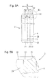
- FIG. 5A shows an anchor rod of an injection drilling anchor suitable for using the coupling according to the invention, according to a preferred embodiment, illustrated in shortened form and partially cut open,
- FIG. 5B shows an enlargement of detail Va according to FIG. 5A .
- FIG. 6A shows the coupling shown in FIG. 4A with only one anchor rod screwed in
- FIG. 6B shows an enlargement of detail Via of FIG. 6A .
- FIGS. 1A to 6B there is presented a preferred exemplary embodiment of a coupling 1 according to the invention as well as an exemplary use preferred within the scope of the invention for producing a coupling arrangement 2 which comprises such a coupling 1 and two anchor rods 3 , for example of an injection drilling anchor, screwed therein for connection.
- FIGS. 4A, 4B show the coupling 1 in a preassembled state
- FIGS. 2 and 3 show the components of the coupling 1 prior to preassembly.
- the coupling 1 comprises a sleeve-like coupling sleeve 4 having two screw-in openings 6 that extend from two opposite ends and are each provided with an internal thread 5 for screwing in support members, for example in each case one of the anchor rods 3 shown in FIGS. 5, 5 a .
- a radially inwardly facing mounting protrusion 7 is formed and extends annularly along the entire periphery.
- the coupling 1 further comprises a clamping ring 11 and two identical sealing rings 12 . Since the clamping ring 11 and the sealing rings 12 are rotationally symmetrical, the sectional view through the center selected in FIG. 3 is in each case sufficient for the illustration thereof.
- the illustration of the preassembled state of the coupling 1 according to FIGS. 4, 4 a shows that the width B of the clamping ring 11 in the example is approximately three times the width b of the mounting protrusion 7 .
- the clamping ring 11 In its middle portion with reference to the longitudinal center axis L, the clamping ring 11 has a cylindrical outer surface 13 , the outside diameter d of which in the example is selected to be slightly smaller than the inside diameter D of the mounting protrusion 7 .
- the outside diameter D 1 of the two sealing rings 12 in the undeformed state shown in FIG. 3 is larger than the inside diameter d of the mounting protrusion 7 and, in the example, is larger than the core diameter D 2 of the internal thread 5 .
- one of the two sealing rings 1 made from elastically deformable plastics has been deformed, starting from its unloaded circular form, between two fingers into an oval form by means of compressive force, and led through one of the two screw-in openings 6 of the coupling sleeve 4 into the hollow interior thereof, has been tilted there into a cross-section perpendicular to the longitudinal center axis L, and in the course of the elastic recovery has been clipped into the recess 8 located there.
- the clamping ring 11 has been inserted through the oppositely situated screw-in opening 6 and into the coupling sleeve 4 approximately up to the position shown in FIG. 4A , in which the hollow cross-section or ring cross-section spanned by the clamping ring 11 lies perpendicularly with respect to the longitudinal center axis L, and in which the clamping ring 11 is positioned in the direction of the longitudinal center axis L, approximately midway, symmetrically with respect to the mounting protrusion 7 and, starting from a geometrical middle line M, extends on both sides into the region of the run-outs 10 of the internal threads 5 .
- the remaining sealing ring 12 has been inserted in a corresponding manner through said oppositely situated screw-in opening 6 and into the coupling sleeve 4 , and clipped therein into the recess 8 remaining for said sealing ring.
- the two sealing rings 12 are accommodated on both sides in the direction of the longitudinal center axis L in an axially captive manner by the formed positive-locking fit.
- the two sealing rings 12 each have a rotationally symmetrical abutment surface 14 (cf. FIG.
- the largest diameter D 3 of the recess 8 corresponds substantially to the outside diameter D 1 of the sealing rings 12 , so that they are substantially held in the coupling sleeve 4 without radial clearance for movement.
- the two sealing rings 12 in conjunction with the axial extent of the recess 8 and the run-outs 10 of the internal threads 5 , lead to the fact that in the preassembled state, the two sealing rings 12 still have a limited clearance for movement in the direction of the longitudinal center axis L, i.e. in the axial direction, whereby in particular clipping in is made easier.
- the sealing rings 12 According to the profile cross-section of the sealing rings 12 shown in FIG. 3 (and, e.g., in FIG. 4B ), the sealing rings each have a radially inner ring portion 18 which, on its side facing toward the mounting protrusion and/or the clamping ring 11 , is bordered by said abutment surface 14 .
- the abutment surface 14 of the sealing rings 12 and the lateral surfaces 16 of the clamping ring 11 are each implemented conically with inclinations or slopes that correlate in terms of magnitude so that these corresponding shapes result in a face-to-face surface support.
- the two sealing rings 12 each have a radially outer ring portion 20 that is connected to the inner ring portion 18 and is bordered by a cylindrical inner surface 21 that transitions with a bend into the abutment surface 14 .
- the inner surface 21 adjoins an end lateral surface 22 for support on an end lateral surface 23 of the mounting protrusion 7 , the lateral surfaces 22 , 23 of the outer ring portion 20 and the mounting protrusion 7 in the profile cross-sections shown in the FIGS. 2, 3 each extending perpendicularly with respect to the geometrical longitudinal center axis L so that a face-to-face surface support is possible.
- the end lateral surface 22 transitions with a curve 24 into a short cylindrical outer surface 25 , the outer surface 25 and the curve 24 , on the one hand, and also that surface of the recess 8 that adjoins the lateral surface 23 of the mounting protrusion 7 , likewise having corresponding cross-sectional profiles for achieving a continuous face-to-face surface support.
- the outer surface 25 transitions in its further course into a back surface 26 that is inclined with respect to said outer surface and extends conically with regard to the geometrical longitudinal center axis L.
- the back surface 26 is inclined more sharply toward the geometrical longitudinal center axis L than the conical run-out 10 of the internal threads 5 , resulting in back clearance that increases toward the sides.
- FIG. 3 additionally shows that the oppositely situated end lateral surfaces 16 of the clamping ring 11 extend conically in a respective radially outer ring surface region 27 and transition in a rounded manner into a radially inner ring surface region 28 that extends straight and perpendicular to the geometrical longitudinal center axis L. It is also provided that the outer ring surface region 27 extends radially inwardly beyond the radius interval 15 of the abutment surface 14 of the sealing ring 12 .
- the coupling 1 according to the invention can be used for connecting two support members, for example two of the anchor rods 3 shown in FIGS. 5A, 5B .
- Such anchor rods 3 which are known per se, have a center channel 29 that passes through along the geometrical longitudinal center axis L of the anchor rods and extends between the two ends.
- the outer circumferential surface carries an external thread 9 , which can be, for example, a coarse thread that is rolled on.
- the internal thread 5 of the coupling sleeve 4 is matched to the external thread 9 for establishing a screw connection.
- 5A, 5B show that the end faces 30 of the anchor rods 3 each have a radially inner, planar end face region 31 that is perpendicular to the geometrical longitudinal center axis L, and radially outward thereof, an end face region 32 that, in the direction of the longitudinal center axis L of the anchor rod 3 , protrudes beyond the inner planar end face region 31 to an increasing extent in the radially outward direction.
- FIG. 1A, 1B and 6A, 6B shows that the radially outer end face region 32 of the anchor rod 3 and the radially outer ring surface portion 27 of the clamping ring 11 in the profile cross-section extend in each case with the same inclination with regard to the geometrical longitudinal axis L of the coupling 1 . Therefore, their shape is matched to one another in such a manner that screwing in the anchor rods 3 into the coupling 1 results in a face-to-face surface support of the radially outer end face regions 32 on the radially outer ring surface region 27 of the clamping ring 11 .
- the outside diameter d 1 of the plane-parallel inner ring surface regions 28 of the clamping ring 11 corresponds to the outside diameter d 2 of the planar, radial inner end face regions 31 of the anchor rods 3
- the inside diameter d 3 of the plane-parallel inner ring surface regions 28 of the clamping ring 22 is equal to the inside diameter d 4 of the radially inner end face regions 31 of the anchor rods 3
- the outside diameter d 5 of the axially projecting outer end face region 32 of the anchor rods 3 at which the axial projection is at a maximum, lies within the radius interval 15 in which the abutment surface 14 of the sealing rings 12 extends in the undeformed state of said sealing rings.
- FIGS. 6A, 6B show an intermediate step which in further course leads to the production and/or assembly of the coupling arrangement 2 shown in FIGS. 1A, 1B .
- an anchor rod 3 has been screwed into the preassembled coupling 1 initially only in one screw-in opening 6 thereof until the end face 30 of the anchor rod rests against the lateral surface 16 of the clamping ring 11 .
- the end face 30 rests face-to-face with its inner end face region 31 and also with its axially projecting end face region 32 located radially outward thereof against the correspondingly formed ring surface regions 28 and 27 of the lateral surface 16 of the clamping ring 11 .
- the anchor rod 3 has a chamfer 33 .
- the first anchor rod 3 is preferably initially screwed into the coupling sleeve 4 until the sealing ring 12 supported on the mounting protrusion 7 permits no further deformation at the selected screw-in force. This corresponds to the intermediate step shown in FIGS. 6A, 6B .
- a further, preferably a corresponding, anchor rod 3 is screwed into the remaining screw-in opening 6 , thereby also deforming the sealing ring 12 situated therein.
- the figures show that the two anchor rods 3 now support one another by means of the clamping ring 11 likewise made of steel, and can be braced against one another with any desired strength or force by means of the two internal threads 5 .
- the sealing rings 12 lie outside of the axial flow of forces which, for example when applying an axial impact force designated by reference character A in FIG. 1A , passes from an anchor rod 3 directly through the clamping ring 11 to the adjacent anchor rod 3 .
- the coupling arrangement shown in FIG. 1A, 1B can be supplemented by additional anchor rods 3 and couplings 1 .
- such an arrangement of couplings 1 and anchor rods 3 can be completed to form an injection drilling anchor by screwing a drill bit known per se (not illustrated in the figures) provided, e.g., with a matching internal thread, onto a free longitudinal end of the most forward anchor rod 3 .
- a drill drive likewise provided with a matching internal thread can be connected, and, by means of the drill drive, a torque, and, if necessary, additional pulsating axial force or impact energy can be transmitted to the injection drilling anchor in order to introduce the latter into the bedrock.
Landscapes
- Engineering & Computer Science (AREA)
- Life Sciences & Earth Sciences (AREA)
- Structural Engineering (AREA)
- Mining & Mineral Resources (AREA)
- General Engineering & Computer Science (AREA)
- General Life Sciences & Earth Sciences (AREA)
- Geology (AREA)
- Mechanical Engineering (AREA)
- Fluid Mechanics (AREA)
- Geochemistry & Mineralogy (AREA)
- Environmental & Geological Engineering (AREA)
- Paleontology (AREA)
- Civil Engineering (AREA)
- Physics & Mathematics (AREA)
- Dowels (AREA)
- Mechanical Operated Clutches (AREA)
- Clamps And Clips (AREA)
- Earth Drilling (AREA)
- Piles And Underground Anchors (AREA)
- Gasket Seals (AREA)
Applications Claiming Priority (4)
| Application Number | Priority Date | Filing Date | Title |
|---|---|---|---|
| DE102010061006A DE102010061006A1 (de) | 2010-12-03 | 2010-12-03 | Kupplung, insbesondere für das Verbinden von Ankerstangen |
| DE102010061006 | 2010-12-03 | ||
| DE102010061006.2 | 2010-12-03 | ||
| PCT/EP2011/071501 WO2012072734A1 (de) | 2010-12-03 | 2011-12-01 | Kupplung, insbesondere für das verbinden von ankerstangen |
Related Parent Applications (1)
| Application Number | Title | Priority Date | Filing Date |
|---|---|---|---|
| PCT/EP2011/071501 Continuation WO2012072734A1 (de) | 2010-12-03 | 2011-12-01 | Kupplung, insbesondere für das verbinden von ankerstangen |
Publications (2)
| Publication Number | Publication Date |
|---|---|
| US20130264819A1 US20130264819A1 (en) | 2013-10-10 |
| US9605780B2 true US9605780B2 (en) | 2017-03-28 |
Family
ID=45218690
Family Applications (1)
| Application Number | Title | Priority Date | Filing Date |
|---|---|---|---|
| US13/908,639 Active 2033-12-30 US9605780B2 (en) | 2010-12-03 | 2013-06-03 | Coupling, in particular for connecting anchor rods |
Country Status (11)
| Country | Link |
|---|---|
| US (1) | US9605780B2 (de) |
| EP (1) | EP2646625B1 (de) |
| AU (1) | AU2011334972B2 (de) |
| CL (1) | CL2013001562A1 (de) |
| CO (1) | CO6700885A2 (de) |
| DE (1) | DE102010061006A1 (de) |
| ES (1) | ES2648813T3 (de) |
| PL (1) | PL2646625T3 (de) |
| RU (1) | RU2573132C2 (de) |
| WO (1) | WO2012072734A1 (de) |
| ZA (1) | ZA201303688B (de) |
Cited By (1)
| Publication number | Priority date | Publication date | Assignee | Title |
|---|---|---|---|---|
| US20160298492A1 (en) * | 2015-04-13 | 2016-10-13 | United Technologies Corporation | Turbine case coupling |
Families Citing this family (8)
| Publication number | Priority date | Publication date | Assignee | Title |
|---|---|---|---|---|
| JP6209461B2 (ja) * | 2014-01-31 | 2017-10-04 | 孝幸 阿部 | 地盤アンカー締付け装置の復元工法 |
| US9261208B1 (en) * | 2014-12-12 | 2016-02-16 | Precision Couplings, Llc | Anti-rotation tubular casing connection and threaded pipe connector |
| RU2651856C1 (ru) * | 2017-03-06 | 2018-04-24 | Акционерное общество "Новомет-Пермь" | Соединение насосно-компрессорных труб |
| CN109209252B (zh) * | 2018-09-19 | 2020-08-21 | 邹城兖矿泰德工贸有限公司 | 耐磨加强型中空接杆 |
| PL3971385T3 (pl) | 2020-09-17 | 2023-07-31 | Sandvik Mining And Construction Tools Ab | Konstrukcja połączenia kolumny wiertniczej |
| US12259068B2 (en) | 2023-08-16 | 2025-03-25 | Hunting Energy Services, Llc | Threaded and coupled tubular connection incorporating a seal ring and method of make-up |
| DE102024117621A1 (de) | 2024-06-21 | 2025-12-24 | Friedr. Ischebeck Gmbh | Einbringspitze für geotechnische Anwendungen, Tragglied und Traggliedsystem |
| CN119618477B (zh) * | 2025-02-13 | 2025-05-06 | 温州力邦企业有限公司 | 一种制动卡钳密封性检测设备 |
Citations (52)
| Publication number | Priority date | Publication date | Assignee | Title |
|---|---|---|---|---|
| US1817776A (en) | 1928-10-23 | 1931-08-04 | Harry E Sipe | Coupling |
| DE568114C (de) | 1930-11-14 | 1933-01-14 | Dardelet Threadlock Corp | Schraubverbindung fuer Gestaenge in Bohrloechern |
| US1952996A (en) | 1931-11-19 | 1934-03-27 | Flannery Bolt Co | Drill |
| DE600537C (de) | 1932-11-01 | 1934-07-26 | Gustavus A Montgomery | Kupplung fuer Bohrgestaenge |
| US2818292A (en) | 1954-04-23 | 1957-12-31 | Carl D Graber | Rock drill |
| US2915322A (en) * | 1956-05-03 | 1959-12-01 | Jersey Prod Res Co | Tubing joint connection |
| AT241362B (de) | 1962-02-16 | 1965-07-26 | Wilhelm Dipl Ing Degen | Verfahren zur Gründung von Bauwerken unterhalb des Grundwasserspiegels |
| US3472533A (en) * | 1968-07-03 | 1969-10-14 | John W Turner | Coupling seal for lined tubular arrangement |
| US3537738A (en) | 1968-04-15 | 1970-11-03 | Sandvikens Jernverks Ab | Drill rod for long hole drilling in the ground |
| DE1784616A1 (de) | 1967-08-29 | 1971-08-19 | Bekaert Sa Nv | Verfahren zum Verankern von Pfosten fuer Verzaunungen,Pfosten und Werkzeug zu seiner Verankerung |
| DE2240935A1 (de) | 1972-08-19 | 1974-02-28 | Dyckerhoff & Widmann Ag | Verfahren zur sicherung von unterwasserbetonsohlen gegen auftrieb und vorrichtung zum durchfuehren des verfahrens |
| AT366777B (de) | 1979-01-27 | 1982-05-10 | Bergwerksverband Gmbh | Rohrfoermiger verlorener bohrlochverschluss |
| US4362419A (en) | 1980-07-28 | 1982-12-07 | Plessey Overseas Limited | Couplings |
| DE3230777A1 (de) | 1981-08-20 | 1983-03-10 | Sumitomo Metal Industries, Ltd., Osaka | Verbindungseinrichtung fuer verrohrungen und herstellungsverfahren dafuer |
| DE3315229A1 (de) | 1982-04-29 | 1983-11-24 | Dril-Quip, Inc., 77040 Houston, Tex. | Verbindungsvorrichtung |
| DE3411519A1 (de) | 1983-04-04 | 1984-10-04 | Robert Alan Houston Tex. Axford | Rohrverbindung |
| EP0131956A1 (de) | 1983-07-18 | 1985-01-23 | Preussag AG | Gewinderohrmuffe |
| DE3400182A1 (de) | 1984-01-04 | 1985-07-11 | Friedr. Ischebeck GmbH, 5828 Ennepetal | Injektionsanker |
| US4537406A (en) * | 1983-04-27 | 1985-08-27 | L'garde, Inc. | Hostile environment joint seal and method for installation |
| US4588213A (en) | 1983-10-05 | 1986-05-13 | Thread Technology International, Inc. | Threaded pipe connection |
| US4616537A (en) * | 1983-04-04 | 1986-10-14 | Awb, Inc. | Pipe connection |
| US4679831A (en) | 1986-06-13 | 1987-07-14 | Kielminski William P | Pipe coupling connection sealing apparatus |
| US4770448A (en) | 1986-09-12 | 1988-09-13 | Landell International Company, Inc. | Pipe coupling |
| DE3717024A1 (de) | 1987-05-21 | 1988-12-01 | Willich F Gmbh & Co | Vorrichtung zum bohren von bohrloechern und injizieren von verfestigungsmaterial |
| US4835873A (en) | 1987-09-16 | 1989-06-06 | Tuboscope, Inc. | Gauging device and method for coupling threaded, tubular articles and a coupling assembly |
| US4875713A (en) | 1985-09-24 | 1989-10-24 | Kenneth J. Carstensen | Internally coated tubular system |
| DE3828335C1 (de) | 1988-08-20 | 1989-11-30 | Friedr. Ischebeck Gmbh, 5828 Ennepetal, De | |
| US4955645A (en) | 1987-09-16 | 1990-09-11 | Tuboscope, Inc. | Gauging device and method for coupling threaded, tubular articles and a coupling assembly |
| DE3910627A1 (de) | 1989-04-01 | 1990-10-04 | Ischebeck Friedrich Gmbh | Verbindungselement |
| DE3927436A1 (de) | 1989-04-28 | 1990-10-31 | Rautenkranz Int Hermann | Hochfeste rohrverbindung fuer schachtfoerderrohrleitungen |
| US4988127A (en) * | 1985-04-24 | 1991-01-29 | Cartensen Kenneth J | Threaded tubing and casing joint |
| DE4116771A1 (de) | 1991-05-23 | 1992-11-26 | Tracto Technik | Vorrichtung zum herstellen von erdbohrungen |
| DE4220636A1 (de) | 1992-06-24 | 1994-01-05 | Ischebeck Friedrich Gmbh | Verbindungselement |
| DE4230636A1 (de) | 1992-09-12 | 1994-03-17 | Daimler Benz Ag | Einrichtung zur Führung von Kabeln elektrischer Einrichtungen eines Personenkraftwagens |
| DE9218985U1 (de) | 1992-03-04 | 1996-10-24 | Challenge Card Design Plastikkarten GmbH, 26180 Rastede | Laminator, Laminatoreinschub und Oberflächenschicht zur Fertigstellung einer Karte, insbesondere einer Identitäts- oder Kreditkarte |
| EP0878584A1 (de) | 1997-05-16 | 1998-11-18 | Gebr. van Leeuwen Harmelen B.V. | Vorrichtung zum Ankuppeln eines Schraubankers an ein Verlängerungsrohr |
| US20020076273A1 (en) | 2000-09-25 | 2002-06-20 | Carstensen Kenneth J. | Connectable rod system for driving downhole pumps for oil field installations |
| DE69901492T2 (de) | 1998-03-26 | 2002-12-19 | Vallourec Mannesmann Oil & Gas France, Aulnoye-Aymeries | Gewindeverbindung von Metallrohren, die ein korrosives Fluid enthalten sollen |
| US20030025328A1 (en) * | 2001-03-28 | 2003-02-06 | Schenk Douglas C. | Threaded pipe connection having a retainer gasket with pressure relief vents |
| DE10225980A1 (de) | 2002-06-11 | 2003-12-24 | Ischebeck Friedrich Gmbh | Verfahren zur auftriebsgesicherten Verankerung von Betonkörpern |
| WO2005047650A1 (en) | 2003-11-13 | 2005-05-26 | Atlas Copco Rock Drills Ab | Tube-formed expandable rock bolt and expansion fluid delivering nozzle |
| US20050248154A1 (en) | 2004-05-05 | 2005-11-10 | Huston Fred N | Threaded connection for oil field applications |
| DE102005022585A1 (de) | 2004-08-06 | 2006-03-16 | Friedr. Ischebeck Gmbh | Bohrvorsatz, insbesondere für eine Belüftungslanze, und Belüftungslanze |
| EP1056968B1 (de) | 1998-02-25 | 2006-04-05 | Grant Prideco, L.P. | Schraubverbindung für innenplattierte rohre |
| DE102005010503B3 (de) | 2005-03-08 | 2006-06-14 | Friedr. Ischebeck Gmbh | Kupplungsmuffe |
| DE102005015494A1 (de) | 2005-04-05 | 2006-10-12 | Friedr. Ischebeck Gmbh | Bajonettkupplung |
| DE60118555T2 (de) | 2000-06-09 | 2007-03-08 | Tesco Corp., Calgary | Verschiebbarer schulterring für eine rohrverbindung |
| DE60120450T2 (de) | 2000-09-29 | 2007-05-16 | Grant Prideco, L.P., The Woodlands | System, verfahren und vorrichtung zum einsatz eines datenbetriebsmittels in einer gewinderohrkupplung |
| WO2008019409A1 (de) | 2006-08-17 | 2008-02-21 | Atlas Copco Mai Gmbh | Reibrohranker und inflationsadapter für diesen |
| WO2008104083A1 (en) | 2007-03-01 | 2008-09-04 | Noetic Engineering Inc. | Shoulder ring with axial retention means, and tools for installing same |
| DE102010016484A1 (de) | 2009-08-20 | 2011-02-24 | Friedr. Ischebeck Gmbh | Kupplung für das Verbinden von Ankerstangen |
| GB2477845A (en) | 2010-02-11 | 2011-08-17 | Screwfast Foundations Ltd | Coupling of tubular sections |
Family Cites Families (3)
| Publication number | Priority date | Publication date | Assignee | Title |
|---|---|---|---|---|
| US5687999A (en) * | 1995-10-03 | 1997-11-18 | Vallourec Oil & Gas | Threaded joint for tubes |
| UA82694C2 (uk) * | 2003-06-06 | 2008-05-12 | Sumitomo Metal Ind | Нарізне з'єднання для сталевих труб |
| EP2096253B1 (de) * | 2008-02-29 | 2010-06-16 | Tenaris Connections AG | Gewindeverbindungsstück mit verbesserten elastischen Dichtungsringen |
-
2010
- 2010-12-03 DE DE102010061006A patent/DE102010061006A1/de not_active Withdrawn
-
2011
- 2011-12-01 RU RU2013130219/03A patent/RU2573132C2/ru active
- 2011-12-01 EP EP11793728.4A patent/EP2646625B1/de active Active
- 2011-12-01 ES ES11793728.4T patent/ES2648813T3/es active Active
- 2011-12-01 AU AU2011334972A patent/AU2011334972B2/en active Active
- 2011-12-01 PL PL11793728T patent/PL2646625T3/pl unknown
- 2011-12-01 WO PCT/EP2011/071501 patent/WO2012072734A1/de not_active Ceased
-
2013
- 2013-05-21 ZA ZA2013/03688A patent/ZA201303688B/en unknown
- 2013-05-27 CO CO13129432A patent/CO6700885A2/es unknown
- 2013-05-31 CL CL2013001562A patent/CL2013001562A1/es unknown
- 2013-06-03 US US13/908,639 patent/US9605780B2/en active Active
Patent Citations (56)
| Publication number | Priority date | Publication date | Assignee | Title |
|---|---|---|---|---|
| US1817776A (en) | 1928-10-23 | 1931-08-04 | Harry E Sipe | Coupling |
| DE568114C (de) | 1930-11-14 | 1933-01-14 | Dardelet Threadlock Corp | Schraubverbindung fuer Gestaenge in Bohrloechern |
| US1952996A (en) | 1931-11-19 | 1934-03-27 | Flannery Bolt Co | Drill |
| DE600537C (de) | 1932-11-01 | 1934-07-26 | Gustavus A Montgomery | Kupplung fuer Bohrgestaenge |
| US2818292A (en) | 1954-04-23 | 1957-12-31 | Carl D Graber | Rock drill |
| US2915322A (en) * | 1956-05-03 | 1959-12-01 | Jersey Prod Res Co | Tubing joint connection |
| AT241362B (de) | 1962-02-16 | 1965-07-26 | Wilhelm Dipl Ing Degen | Verfahren zur Gründung von Bauwerken unterhalb des Grundwasserspiegels |
| DE1784616A1 (de) | 1967-08-29 | 1971-08-19 | Bekaert Sa Nv | Verfahren zum Verankern von Pfosten fuer Verzaunungen,Pfosten und Werkzeug zu seiner Verankerung |
| US3537738A (en) | 1968-04-15 | 1970-11-03 | Sandvikens Jernverks Ab | Drill rod for long hole drilling in the ground |
| US3472533A (en) * | 1968-07-03 | 1969-10-14 | John W Turner | Coupling seal for lined tubular arrangement |
| DE2240935A1 (de) | 1972-08-19 | 1974-02-28 | Dyckerhoff & Widmann Ag | Verfahren zur sicherung von unterwasserbetonsohlen gegen auftrieb und vorrichtung zum durchfuehren des verfahrens |
| AT366777B (de) | 1979-01-27 | 1982-05-10 | Bergwerksverband Gmbh | Rohrfoermiger verlorener bohrlochverschluss |
| US4362440A (en) | 1979-01-27 | 1982-12-07 | Bergwerksverband Gmbh | Tubular lost borehole closure |
| US4362419A (en) | 1980-07-28 | 1982-12-07 | Plessey Overseas Limited | Couplings |
| DE3230777A1 (de) | 1981-08-20 | 1983-03-10 | Sumitomo Metal Industries, Ltd., Osaka | Verbindungseinrichtung fuer verrohrungen und herstellungsverfahren dafuer |
| DE3315229A1 (de) | 1982-04-29 | 1983-11-24 | Dril-Quip, Inc., 77040 Houston, Tex. | Verbindungsvorrichtung |
| US4616537A (en) * | 1983-04-04 | 1986-10-14 | Awb, Inc. | Pipe connection |
| DE3411519A1 (de) | 1983-04-04 | 1984-10-04 | Robert Alan Houston Tex. Axford | Rohrverbindung |
| US4568113A (en) | 1983-04-04 | 1986-02-04 | Awb, Inc. | Pipe connection |
| US4537406A (en) * | 1983-04-27 | 1985-08-27 | L'garde, Inc. | Hostile environment joint seal and method for installation |
| EP0131956A1 (de) | 1983-07-18 | 1985-01-23 | Preussag AG | Gewinderohrmuffe |
| US4588213A (en) | 1983-10-05 | 1986-05-13 | Thread Technology International, Inc. | Threaded pipe connection |
| DE3400182A1 (de) | 1984-01-04 | 1985-07-11 | Friedr. Ischebeck GmbH, 5828 Ennepetal | Injektionsanker |
| US4988127A (en) * | 1985-04-24 | 1991-01-29 | Cartensen Kenneth J | Threaded tubing and casing joint |
| US4875713A (en) | 1985-09-24 | 1989-10-24 | Kenneth J. Carstensen | Internally coated tubular system |
| US4679831A (en) | 1986-06-13 | 1987-07-14 | Kielminski William P | Pipe coupling connection sealing apparatus |
| US4770448A (en) | 1986-09-12 | 1988-09-13 | Landell International Company, Inc. | Pipe coupling |
| DE3717024A1 (de) | 1987-05-21 | 1988-12-01 | Willich F Gmbh & Co | Vorrichtung zum bohren von bohrloechern und injizieren von verfestigungsmaterial |
| US4955645A (en) | 1987-09-16 | 1990-09-11 | Tuboscope, Inc. | Gauging device and method for coupling threaded, tubular articles and a coupling assembly |
| US4835873A (en) | 1987-09-16 | 1989-06-06 | Tuboscope, Inc. | Gauging device and method for coupling threaded, tubular articles and a coupling assembly |
| DE3828335C1 (de) | 1988-08-20 | 1989-11-30 | Friedr. Ischebeck Gmbh, 5828 Ennepetal, De | |
| DE3910627A1 (de) | 1989-04-01 | 1990-10-04 | Ischebeck Friedrich Gmbh | Verbindungselement |
| EP0391119A1 (de) | 1989-04-01 | 1990-10-10 | Friedr. Ischebeck GmbH | Verbindungselement für eine Schraubverbindung von selbstbohrenden Injektionsankern |
| DE3927436A1 (de) | 1989-04-28 | 1990-10-31 | Rautenkranz Int Hermann | Hochfeste rohrverbindung fuer schachtfoerderrohrleitungen |
| DE4116771A1 (de) | 1991-05-23 | 1992-11-26 | Tracto Technik | Vorrichtung zum herstellen von erdbohrungen |
| DE9218985U1 (de) | 1992-03-04 | 1996-10-24 | Challenge Card Design Plastikkarten GmbH, 26180 Rastede | Laminator, Laminatoreinschub und Oberflächenschicht zur Fertigstellung einer Karte, insbesondere einer Identitäts- oder Kreditkarte |
| DE4220636A1 (de) | 1992-06-24 | 1994-01-05 | Ischebeck Friedrich Gmbh | Verbindungselement |
| DE4230636A1 (de) | 1992-09-12 | 1994-03-17 | Daimler Benz Ag | Einrichtung zur Führung von Kabeln elektrischer Einrichtungen eines Personenkraftwagens |
| EP0878584A1 (de) | 1997-05-16 | 1998-11-18 | Gebr. van Leeuwen Harmelen B.V. | Vorrichtung zum Ankuppeln eines Schraubankers an ein Verlängerungsrohr |
| EP1056968B1 (de) | 1998-02-25 | 2006-04-05 | Grant Prideco, L.P. | Schraubverbindung für innenplattierte rohre |
| DE69901492T2 (de) | 1998-03-26 | 2002-12-19 | Vallourec Mannesmann Oil & Gas France, Aulnoye-Aymeries | Gewindeverbindung von Metallrohren, die ein korrosives Fluid enthalten sollen |
| DE60118555T2 (de) | 2000-06-09 | 2007-03-08 | Tesco Corp., Calgary | Verschiebbarer schulterring für eine rohrverbindung |
| US20020076273A1 (en) | 2000-09-25 | 2002-06-20 | Carstensen Kenneth J. | Connectable rod system for driving downhole pumps for oil field installations |
| DE60120450T2 (de) | 2000-09-29 | 2007-05-16 | Grant Prideco, L.P., The Woodlands | System, verfahren und vorrichtung zum einsatz eines datenbetriebsmittels in einer gewinderohrkupplung |
| US20030025328A1 (en) * | 2001-03-28 | 2003-02-06 | Schenk Douglas C. | Threaded pipe connection having a retainer gasket with pressure relief vents |
| DE10225980A1 (de) | 2002-06-11 | 2003-12-24 | Ischebeck Friedrich Gmbh | Verfahren zur auftriebsgesicherten Verankerung von Betonkörpern |
| WO2005047650A1 (en) | 2003-11-13 | 2005-05-26 | Atlas Copco Rock Drills Ab | Tube-formed expandable rock bolt and expansion fluid delivering nozzle |
| US20050248154A1 (en) | 2004-05-05 | 2005-11-10 | Huston Fred N | Threaded connection for oil field applications |
| DE102005022585A1 (de) | 2004-08-06 | 2006-03-16 | Friedr. Ischebeck Gmbh | Bohrvorsatz, insbesondere für eine Belüftungslanze, und Belüftungslanze |
| DE102005010503B3 (de) | 2005-03-08 | 2006-06-14 | Friedr. Ischebeck Gmbh | Kupplungsmuffe |
| DE102005015494A1 (de) | 2005-04-05 | 2006-10-12 | Friedr. Ischebeck Gmbh | Bajonettkupplung |
| WO2008019409A1 (de) | 2006-08-17 | 2008-02-21 | Atlas Copco Mai Gmbh | Reibrohranker und inflationsadapter für diesen |
| WO2008104083A1 (en) | 2007-03-01 | 2008-09-04 | Noetic Engineering Inc. | Shoulder ring with axial retention means, and tools for installing same |
| DE102010016484A1 (de) | 2009-08-20 | 2011-02-24 | Friedr. Ischebeck Gmbh | Kupplung für das Verbinden von Ankerstangen |
| WO2011020696A2 (de) | 2009-08-20 | 2011-02-24 | Friedr. Ischebeck Gmbh | Kupplung für das verbinden von ankerstangen |
| GB2477845A (en) | 2010-02-11 | 2011-08-17 | Screwfast Foundations Ltd | Coupling of tubular sections |
Non-Patent Citations (2)
| Title |
|---|
| German Search Report, Application No. 10 2010 061 006.2, Dated: Aug. 28, 2015; Received: Jan. 3, 2016, 4 pages. |
| International Search Report, Application No. PCT/EP2011/071501, Completed: May 11, 2012; Mailing Date: May 21, 2012, 2 pages. |
Cited By (2)
| Publication number | Priority date | Publication date | Assignee | Title |
|---|---|---|---|---|
| US20160298492A1 (en) * | 2015-04-13 | 2016-10-13 | United Technologies Corporation | Turbine case coupling |
| US10519805B2 (en) * | 2015-04-13 | 2019-12-31 | United Technologies Corporation | Turbine case coupling |
Also Published As
| Publication number | Publication date |
|---|---|
| CL2013001562A1 (es) | 2013-10-25 |
| AU2011334972A1 (en) | 2013-06-06 |
| RU2013130219A (ru) | 2015-01-10 |
| RU2573132C2 (ru) | 2016-01-20 |
| AU2011334972B2 (en) | 2016-12-22 |
| EP2646625B1 (de) | 2017-11-15 |
| DE102010061006A1 (de) | 2012-06-06 |
| PL2646625T3 (pl) | 2018-03-30 |
| US20130264819A1 (en) | 2013-10-10 |
| ES2648813T3 (es) | 2018-01-08 |
| ZA201303688B (en) | 2014-07-30 |
| CO6700885A2 (es) | 2013-06-28 |
| WO2012072734A1 (de) | 2012-06-07 |
| EP2646625A1 (de) | 2013-10-09 |
Similar Documents
| Publication | Publication Date | Title |
|---|---|---|
| US9605780B2 (en) | Coupling, in particular for connecting anchor rods | |
| US3477750A (en) | Pipe coupling and means and method of assembly | |
| US5909980A (en) | Tubular coupler for concrete reinforcing bars | |
| US20040071507A1 (en) | Reinforcing bar coupling | |
| KR102435963B1 (ko) | 결합 장치, 연관된 부품들, 및 그것의 사용 방법 | |
| US5664902A (en) | Tubular coupler for concrete reinforcing bars | |
| JP6833709B2 (ja) | スエージ継手 | |
| US20100003101A1 (en) | Wedge-type drop-in anchor assembly | |
| EP0480478A1 (de) | Rohrkupplung | |
| CN110249168A (zh) | 用于机械和结构管件的机械联接件 | |
| CN105333249A (zh) | 具有径向负荷的卡套夹头 | |
| US7484772B2 (en) | End connection for pipes and a method for its manufacture | |
| EP1250500A1 (de) | Befestigung | |
| US20200108475A1 (en) | Press-in connecting element and method for anchoring press-in connecting elements in a permanently deformable flat metal material or components or workpieces produced therefrom | |
| CN104863947A (zh) | 空心铆钉紧固件 | |
| US20070096461A1 (en) | Crimped hose fitting | |
| JP3225398B2 (ja) | ワンサイドボルト | |
| JPH11336257A (ja) | 鉄筋用連結装置 | |
| JP2000145383A (ja) | セグメントの連結工法及び継手構造 | |
| CN216865120U (zh) | 插接配合组件、插接结构及预制桩连接机构 | |
| EP1467109A1 (de) | Befestigungselement mit Gewinde | |
| US6241443B1 (en) | Fastener with staged locking system | |
| JP2008127824A (ja) | 建築構造物の連結方法及びその連結部材 | |
| JPH1162920A (ja) | ブラインドジョイント及びその施工方法 | |
| JP2007198099A (ja) | セグメントの継手構造 |
Legal Events
| Date | Code | Title | Description |
|---|---|---|---|
| AS | Assignment |
Owner name: FRIEDR. ISCHEBECK GMBH, GERMANY Free format text: ASSIGNMENT OF ASSIGNORS INTEREST;ASSIGNORS:ISCHEBECK, ERNST FRIEDRICH;COERSCHULTE, FERDINAND;SIGNING DATES FROM 20130523 TO 20130604;REEL/FRAME:030894/0136 |
|
| STCF | Information on status: patent grant |
Free format text: PATENTED CASE |
|
| MAFP | Maintenance fee payment |
Free format text: PAYMENT OF MAINTENANCE FEE, 4TH YEAR, LARGE ENTITY (ORIGINAL EVENT CODE: M1551); ENTITY STATUS OF PATENT OWNER: LARGE ENTITY Year of fee payment: 4 |
|
| MAFP | Maintenance fee payment |
Free format text: PAYMENT OF MAINTENANCE FEE, 8TH YEAR, LARGE ENTITY (ORIGINAL EVENT CODE: M1552); ENTITY STATUS OF PATENT OWNER: LARGE ENTITY Year of fee payment: 8 |