US9855159B2 - Stent and stent delivery system - Google Patents
Stent and stent delivery system Download PDFInfo
- Publication number
- US9855159B2 US9855159B2 US14/035,136 US201314035136A US9855159B2 US 9855159 B2 US9855159 B2 US 9855159B2 US 201314035136 A US201314035136 A US 201314035136A US 9855159 B2 US9855159 B2 US 9855159B2
- Authority
- US
- United States
- Prior art keywords
- stent
- parts
- apex
- curved
- axial end
- Prior art date
- Legal status (The legal status is an assumption and is not a legal conclusion. Google has not performed a legal analysis and makes no representation as to the accuracy of the status listed.)
- Expired - Fee Related, expires
Links
Images



Classifications
-
- A—HUMAN NECESSITIES
- A61—MEDICAL OR VETERINARY SCIENCE; HYGIENE
- A61F—FILTERS IMPLANTABLE INTO BLOOD VESSELS; PROSTHESES; DEVICES PROVIDING PATENCY TO, OR PREVENTING COLLAPSING OF, TUBULAR STRUCTURES OF THE BODY, e.g. STENTS; ORTHOPAEDIC, NURSING OR CONTRACEPTIVE DEVICES; FOMENTATION; TREATMENT OR PROTECTION OF EYES OR EARS; BANDAGES, DRESSINGS OR ABSORBENT PADS; FIRST-AID KITS
- A61F2/00—Filters implantable into blood vessels; Prostheses, i.e. artificial substitutes or replacements for parts of the body; Appliances for connecting them with the body; Devices providing patency to, or preventing collapsing of, tubular structures of the body, e.g. stents
- A61F2/95—Instruments specially adapted for placement or removal of stents or stent-grafts
- A61F2/958—Inflatable balloons for placing stents or stent-grafts
-
- A—HUMAN NECESSITIES
- A61—MEDICAL OR VETERINARY SCIENCE; HYGIENE
- A61F—FILTERS IMPLANTABLE INTO BLOOD VESSELS; PROSTHESES; DEVICES PROVIDING PATENCY TO, OR PREVENTING COLLAPSING OF, TUBULAR STRUCTURES OF THE BODY, e.g. STENTS; ORTHOPAEDIC, NURSING OR CONTRACEPTIVE DEVICES; FOMENTATION; TREATMENT OR PROTECTION OF EYES OR EARS; BANDAGES, DRESSINGS OR ABSORBENT PADS; FIRST-AID KITS
- A61F2/00—Filters implantable into blood vessels; Prostheses, i.e. artificial substitutes or replacements for parts of the body; Appliances for connecting them with the body; Devices providing patency to, or preventing collapsing of, tubular structures of the body, e.g. stents
- A61F2/82—Devices providing patency to, or preventing collapsing of, tubular structures of the body, e.g. stents
- A61F2/86—Stents in a form characterised by the wire-like elements; Stents in the form characterised by a net-like or mesh-like structure
- A61F2/90—Stents in a form characterised by the wire-like elements; Stents in the form characterised by a net-like or mesh-like structure characterised by a net-like or mesh-like structure
- A61F2/91—Stents in a form characterised by the wire-like elements; Stents in the form characterised by a net-like or mesh-like structure characterised by a net-like or mesh-like structure made from perforated sheets or tubes, e.g. perforated by laser cuts or etched holes
- A61F2/915—Stents in a form characterised by the wire-like elements; Stents in the form characterised by a net-like or mesh-like structure characterised by a net-like or mesh-like structure made from perforated sheets or tubes, e.g. perforated by laser cuts or etched holes with bands having a meander structure, adjacent bands being connected to each other
-
- A—HUMAN NECESSITIES
- A61—MEDICAL OR VETERINARY SCIENCE; HYGIENE
- A61F—FILTERS IMPLANTABLE INTO BLOOD VESSELS; PROSTHESES; DEVICES PROVIDING PATENCY TO, OR PREVENTING COLLAPSING OF, TUBULAR STRUCTURES OF THE BODY, e.g. STENTS; ORTHOPAEDIC, NURSING OR CONTRACEPTIVE DEVICES; FOMENTATION; TREATMENT OR PROTECTION OF EYES OR EARS; BANDAGES, DRESSINGS OR ABSORBENT PADS; FIRST-AID KITS
- A61F2/00—Filters implantable into blood vessels; Prostheses, i.e. artificial substitutes or replacements for parts of the body; Appliances for connecting them with the body; Devices providing patency to, or preventing collapsing of, tubular structures of the body, e.g. stents
- A61F2/82—Devices providing patency to, or preventing collapsing of, tubular structures of the body, e.g. stents
- A61F2/86—Stents in a form characterised by the wire-like elements; Stents in the form characterised by a net-like or mesh-like structure
- A61F2/90—Stents in a form characterised by the wire-like elements; Stents in the form characterised by a net-like or mesh-like structure characterised by a net-like or mesh-like structure
- A61F2/91—Stents in a form characterised by the wire-like elements; Stents in the form characterised by a net-like or mesh-like structure characterised by a net-like or mesh-like structure made from perforated sheets or tubes, e.g. perforated by laser cuts or etched holes
- A61F2/915—Stents in a form characterised by the wire-like elements; Stents in the form characterised by a net-like or mesh-like structure characterised by a net-like or mesh-like structure made from perforated sheets or tubes, e.g. perforated by laser cuts or etched holes with bands having a meander structure, adjacent bands being connected to each other
- A61F2002/9155—Adjacent bands being connected to each other
- A61F2002/91558—Adjacent bands being connected to each other connected peak to peak
-
- A—HUMAN NECESSITIES
- A61—MEDICAL OR VETERINARY SCIENCE; HYGIENE
- A61F—FILTERS IMPLANTABLE INTO BLOOD VESSELS; PROSTHESES; DEVICES PROVIDING PATENCY TO, OR PREVENTING COLLAPSING OF, TUBULAR STRUCTURES OF THE BODY, e.g. STENTS; ORTHOPAEDIC, NURSING OR CONTRACEPTIVE DEVICES; FOMENTATION; TREATMENT OR PROTECTION OF EYES OR EARS; BANDAGES, DRESSINGS OR ABSORBENT PADS; FIRST-AID KITS
- A61F2230/00—Geometry of prostheses classified in groups A61F2/00 - A61F2/26 or A61F2/82 or A61F9/00 or A61F11/00 or subgroups thereof
- A61F2230/0002—Two-dimensional shapes, e.g. cross-sections
- A61F2230/0004—Rounded shapes, e.g. with rounded corners
- A61F2230/0013—Horseshoe-shaped, e.g. crescent-shaped, C-shaped, U-shaped
-
- A—HUMAN NECESSITIES
- A61—MEDICAL OR VETERINARY SCIENCE; HYGIENE
- A61F—FILTERS IMPLANTABLE INTO BLOOD VESSELS; PROSTHESES; DEVICES PROVIDING PATENCY TO, OR PREVENTING COLLAPSING OF, TUBULAR STRUCTURES OF THE BODY, e.g. STENTS; ORTHOPAEDIC, NURSING OR CONTRACEPTIVE DEVICES; FOMENTATION; TREATMENT OR PROTECTION OF EYES OR EARS; BANDAGES, DRESSINGS OR ABSORBENT PADS; FIRST-AID KITS
- A61F2230/00—Geometry of prostheses classified in groups A61F2/00 - A61F2/26 or A61F2/82 or A61F9/00 or A61F11/00 or subgroups thereof
- A61F2230/0002—Two-dimensional shapes, e.g. cross-sections
- A61F2230/0028—Shapes in the form of latin or greek characters
- A61F2230/0054—V-shaped
-
- F—MECHANICAL ENGINEERING; LIGHTING; HEATING; WEAPONS; BLASTING
- F04—POSITIVE - DISPLACEMENT MACHINES FOR LIQUIDS; PUMPS FOR LIQUIDS OR ELASTIC FLUIDS
- F04C—ROTARY-PISTON, OR OSCILLATING-PISTON, POSITIVE-DISPLACEMENT MACHINES FOR LIQUIDS; ROTARY-PISTON, OR OSCILLATING-PISTON, POSITIVE-DISPLACEMENT PUMPS
- F04C2270/00—Control; Monitoring or safety arrangements
- F04C2270/04—Force
- F04C2270/042—Force radial
- F04C2270/0421—Controlled or regulated
Definitions
- the present invention generally relates to a stent and a stent delivery system.
- a stent delivery system is a medical device used for improving a stenosis or occluded part in a lumen in a living body.
- the stent delivery system is provided with an inflatable balloon which is disposed on the outer circumference of a distal end portion of a hollow shaft section, and a stent which is composed of wavy linear members, is disposed on the outer circumference of the balloon and is expanded by inflation of the balloon.
- the stent is caulked (mounted) onto the balloon while the balloon is in a radially contracted state.
- the balloon After arrival in a target part (stenosis or occluded part), the balloon is inflated to bring the stent into plastic deformation, whereby the stent is put indwelling (indwelled) in secure contact with the inner surface of the target part.
- the stent may fail to spread uniformly in the circumferential direction, so that the stent may be unable to display its intended performance.
- a stent in general extremely small, about 100 ⁇ m.
- a stent in practical use receives forces in various directions from a blood vessel wall or the like.
- the stents like the one disclosed in Japanese Application Publication No. 2000-516486 therefore, it may be difficult to successfully achieve the intended engagement, and the stent may be expanded nonuniformly.
- the problem that nonuniform expansion of the stent cannot be avoided assuredly.
- a stent positionable on an outer circumference of an inflatable balloon and expandable by inflation of the balloon wherein the stent includes: a circumferentially extending wavy-shaped member which is expandable and contractable in the radial direction of the stent; with the circumferentially extending wavy-shaped member including a pair of straight parts, an apex part, and an opening; with the apex part possessing opposite ends each connected to one of the straight parts; with the opening located at least in the apex part; and with the apex part including a link part located to an outer circumferential side of the opening and a base part located to an inner circumferential side of the opening.
- the base part possesses a curved inner circumference, the link part lies across a vertex of the base part, and the link part possesses a width in relation to the circumferential direction of the stent is smaller than a width of the base part in relation to the circumferential direction of the stent, at the vertex of the base part.
- a stent is positionable on an inflatable balloon in surrounding relation to an outer circumference of the balloon, with the balloon being expandable by inflating the balloon.
- the stent includes: a plurality of annular members arranged in an axially extending manner, with axially adjacent annular members connected to one another; with each of the annular members comprised of a circumferentially extending wavy-shaped member which is expandable and contractable in the radial direction of the stent, and each of the annular members possessing one axial end and an other axial end; and wherein each of the circumferentially extending wavy members includes a plurality of curved apex parts at the one axial end of the annular member and a plurality of curved apex parts at the other axial end of the annular member.
- An opening is located in a plurality of the curved apex parts at the one axial end of each annular member, and an opening is located in a plurality of the curved apex parts at the other axial end of each annular member, with each of the openings at the one axial end being completely surrounded by material forming the curved apex of each annular member and each of the openings at the other axial end being completely surrounded by material forming the curved apex of each annular member.
- Each of the plurality of curved apex parts at the one axial end of each annular member, and each of the apex parts at the other axial end of each annular member include a link part located radially outwardly of the opening and a base part located radially inwardly of the opening, wherein the base part possesses a curved inner circumference, the link part lies across a vertex of the base part, and the link part and the base part both possess a width, with the width of the link part in relation to the circumferential direction of the stent being smaller than the width of the base part in relation to the circumferential direction of the stent, at the vertex of the base part.
- a stent delivery system that includes a balloon catheter including a hollow shaft section and an inflatable balloon disposed on an outer circumference of a distal end portion of the shaft section, and a stent disposed on an outer circumference of the balloon and expanded by inflation of the balloon.
- the stent includes: a circumferentially extending wavy-shaped member which is expandable and contractable in the radial direction of the stent; with the circumferentially extending wavy-shaped member including a pair of straight parts, an apex part, and an opening; with the apex part possessing opposite ends each connected to one of the straight parts; with the opening located at least in the apex part; and with the apex part including a link part located to an outer circumferential side of the opening and a base part located to an inner circumferential side of the opening.
- the base part possesses a curved inner circumference, the link part lies across a vertex of the base part, and the link part possesses a width in relation to the circumferential direction of the stent is smaller than a width of the base part in relation to the circumferential direction of the stent, at the vertex of the base part.
- the link part disposed at the apex part in which the deformation is concentrated displays a springy action (elasticity), whereby plastic deformation of the base part of the apex part in which the deformation is concentrated is restrained.
- the base part has a curved inner circumference
- the link part lies across the vertex of the base part
- the width of the link part in relation to the circumferential direction of the stent is smaller than the width of the base part in relation to the circumferential direction of the stent, at the vertex of the base part.
- the outer circumference of that portion of the link part which is opposite to the vertex has a curved shape.
- the springy action of the link part can be displayed effectively.
- the radius of curvature of the outer circumference of the link part is preferably greater than the radius of curvature of the inner circumference of the base part.
- the linear member preferably constitutes an annular body, and a plurality of such annular bodies are arranged along the axial direction of the stent.
- the strength with which the stent is fixed to the balloon (stent retaining force) can be enhanced, and drop-off of the stent from the balloon can be restrained reliably.
- the annular bodies adjacent to each other along the axial direction of the stent are preferably integrated through a connecting part.
- the strength with which the stent is fixed to the balloon (stent retaining force) can thus be enhanced, and drop-off of the stent from the balloon can be restrained assuredly.
- some of the apex parts are connected to one of the connecting part and some of the apex parts are not connected to any of the connecting parts.
- the apex parts will this be relatively easily deformed, so that the stent will be expanded more easily.
- FIG. 1 is a plan view of a stent delivery system according to an embodiment disclosed here.
- FIG. 2 is a partial cross-sectional view illustrating a use for the stent delivery system shown in FIG. 1 .
- FIG. 3 is a longitudinal cross-sectional view of the distal end portion of the stent delivery system shown in FIG. 1 , illustrating also the stent.
- FIG. 4 is a partial development view illustrating an initial state of the stent shown in FIG. 3 .
- FIG. 5 is a partial development view illustrating an expanded state of the stent shown in FIG. 3 .
- FIG. 6 is a somewhat conceptual view illustrating the deformation of a wavy-shaped linear member shown in FIG. 5 into an expanded state.
- FIG. 7 is an illustration of modification 1 according to another embodiment disclosed here.
- FIG. 8 is an illustration of modification 2 according to an additional embodiment disclosed here.
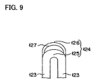
- FIG. 9 is an illustration of modification 3 according to a further embodiment disclosed here.
- the stent delivery system 100 is used to improve a stenosis (or occluded part) 182 generated in a lumen 180 in a living body (see FIG. 2 ).
- the stent delivery system 100 includes a tubular shaft (shaft section) 160 , a balloon 130 disposed on the outer circumference of a distal end portion of the tubular shaft 160 , a stent 120 disposed on the outer circumference of the balloon 130 , and a hub 140 located at a proximal portion of the tubular shaft 160 .
- the lumen 180 in the living body is, for example, a coronary artery of the heart.
- One of the purposes of indwelling the stent 120 in the lumen of the living body is to prevent restenosis after PTCA (Percutaneous Transluminal coronary Angioplasty).
- the mode of using the stent delivery system 100 is not restricted to the mode of applying it to a stenosis generated in the coronary artery of the heart, and it may be applied also to a stenosis generated in other blood vessels, bile duct, trachea, esophagus, urethra and the like.
- the stent 120 is a medical device to be put indwelling in secure contact with the inner surface of the stenosis 182 , to thereby maintain the patency (open condition) of the lumen 180 .
- the stent 120 is configured to be expandable.
- the stent 120 is engaged with the balloon 130 so as to restrain positional deviation or peeling (separation) of the stent 120 from the balloon 130 .
- the stent 120 is so configured that uniform expansion thereof can be securely achieved, as described later.
- the balloon 130 is so configured that it can be freely inflatable so as to expand, and to enlarge the radius of, the stent 120 disposed on the outer circumference thereof.
- the hub 140 has an injection port 142 and a guide wire port 144 .
- the injection port 142 is used, for example, for introducing and discharging a pressure fluid which is used for inflating the balloon 130 .
- the pressure fluid is, for example, a liquid such as physiological saline and an angiographic contrast agent.
- the guide wire port 144 is used for inserting a guide wire 150 into the tubular shaft 160 and protruding the guide wire 150 beyond a distal end portion of the tubular shaft 160 .
- Putting the stent 120 in the lumen of the living body i.e., indwelling the stent is carried out, for example, as follows.
- a distal end portion of the stent delivery system 100 is inserted into the lumen 180 of a patient, and is positioned into the stenosis 182 , which is the target part, while the guide wire 150 having preliminarily been protruded beyond the distal end portion of the tubular shaft 160 is advanced in a preceding manner.
- the pressure fluid is introduced via the injection port 142 to inflate the balloon 130 , thereby causing expansion and plastic deformation of the stent 120 , whereby the stent 120 securely contacts the stenosis 182 (see FIG. 2 ).
- the balloon 130 is deflated, to disengage the stent 120 and the balloon 130 from each other, thereby separating the stent 120 from the balloon 130 .
- the stent 120 is set indwelling (indwelled) in the stenosis 182 .
- the stent delivery system 100 from which the stent 120 has thus been separated is moved backward, to be removed from the lumen 180 .
- the balloon 130 is disposed along the axial direction A in relation to the outer circumference of the distal end portion of the tubular shaft 160 , in a folded state (or a contracted state), and is freely inflatable.
- the stent 120 is disposed on the outer circumference of the balloon 130 , in a radially contracted state. With the balloon 130 inflated, a linear member in the form of a wavy-shaped member 122 of the stent 120 is expanded.
- the material forming the balloon 130 is preferably a flexible material.
- the flexible material include polyolefin, polyvinyl chloride, polyamides, polyamide elastomers, polyurethane, polyesters such as polyethylene terephthalate, etc., polyarylene sulfides such as polyphenylene sulfide, silicone rubbers, and latex rubber.
- the polyolefin include polyethylene, polypropylene, ethylene-propylene copolymer, ethylene-vinyl acetate copolymer, and crosslinked ethylene-vinyl acetate copolymer.
- the stent 120 is formed from a biocompatible material.
- the biocompatible material include nickel-titanium alloys, cobalt-chromium alloys, stainless steels, iron, titanium, aluminum, tin, and zinc-tungsten alloys.
- the tubular shaft 160 includes an inner tube 162 , and an outer tube 164 in which the inner tube 162 is positioned.
- the inner tube 162 communicates with the guide wire port 144 of the hub 140 , and penetrates the balloon 130 to extend to the distal end of the balloon 130 . Therefore, the guide wire 150 inserted in the guide wire port 144 can freely protrude beyond the distal end of the stent delivery system 100 , and the inside of the inner tube 162 constitutes a guide wire lumen 161 .
- Cylindrical markers 170 are mounted on the outer circumference of the inner tube 162 , inside the balloon 130 .
- the markers 170 are formed from a radiopaque material, so that clear contrast images of them can be obtained under radioscopy. This helps ensure that the positions of the balloon 130 and the stent 120 can be rather easily confirmed.
- the radiopaque material include platinum, gold, tungsten, iridium, and their alloys.
- the outer tube 164 is disposed outside the inner tube 162 .
- a space exists between the inner circumferential surface of the outer tube 164 and the outer circumferential surface of the inner tube 162 , and this space defines a lumen 163 which communicates with the injection port 142 of the hub 140 .
- the balloon 130 is fixed in a liquid-tight manner to the outer circumference of the distal end portion of the inner tube 162 and to the outer circumference of the distal end portion of the outer tube 164 .
- the inside of the balloon 130 communicates with the lumen 163 . Therefore, the pressure fluid introduced via the injection port 142 can pass through the lumen 163 , to be introduced into the inside of the balloon 130 , thereby inflating the balloon 130 .
- the method of fixing the balloon 130 to the outer circumferences of the distal end portions of the inner tube 162 and the outer tube 164 is not specifically restricted; for example, an adhesive or heat fusing may be employed.
- the material constituting the outer tube 164 is preferably a flexible material.
- the flexible material include polyolefins such as polyethylene, polypropylene, polybutene, ethylene-propylene copolymer, ethylene-vinyl acetate copolymer, ionomers, mixtures of two or more of them, etc., thermoplastic resins such as soft polyvinyl chloride resin, polyamides, polyamide elastomers, polyesters, polyester elastomers, polyurethane, fluororesins, etc., silicone rubbers, and latex rubber.
- the same materials as those for the outer tube 164 and metallic materials are applicable.
- the metallic materials include stainless steels and Ni—Ti alloys.
- Examples of the material constituting the hub 140 include thermoplastic resins such as polycarbonate, polyamides, polysulfones, polyarylates, and methacrylate-butylene-styrene copolymer.
- the stent 120 includes linear members 122 that are wavy-shaped and extend in the circumferential direction C of the stent and which can be expanded and contracted in the radial direction of the stent.
- the wavy-shaped members 122 constitute an annular body.
- a plurality of such annular bodies are arranged along the axial direction A, and the axially adjacent annular bodies are integrated or connected to each other through connecting parts 128 . This helps ensure that the strength with which the stent is fixed to the balloon 130 (stent retaining force) is enhanced, and drop-off of the stent from the balloon 130 is securely restrained.
- Each wavy-shaped member 122 includes a plurality of circumferentially spaced apart straight parts 123 , a plurality of circumferentially spaced apart apex parts 124 and 129 at both axial ends of the wavy-shaped member 122 , and an opening 127 at the apex parts 124 , 129 .
- each end of each apex part 124 , 129 is connected to one of the straight parts 123 .
- an opening 127 is preferably located in each of the apex parts 124 , 129 .
- the apex parts 124 , 129 each include a link part 126 composed of a portion of the apex part which is located on the outer circumferential side relative to the opening 127 , and a base part 125 composed of a portion of the apex part which is located to the inner circumferential side relative to the opening 127 .
- the opening 127 is preferably provided in every one of the apex parts 124 and 129 of the wavy-shaped members 122 .
- each opening 127 is elliptical in shape.
- the straight parts 123 are straight over their entire length. But it is also sufficient that the straight parts 123 are straight in shape at least along a part of their length, particularly in the vicinity of both ends of the straight part connected to the apex parts 124 and 129 . Thus, the straight parts 123 may have a gently curved portion at their intermediate portion, for example.
- the wavelength W or the distance between the apexes (apex points) of apex parts 124 and 129 that are circumferentially adjacent each other in the circumferential direction C of the stent, is substantially constant.
- the amplitude V or the distance between the apexes (apex points) of the apex parts 124 and 129 located at (connected to) opposite ends of the straight part 123 , is substantially constant.
- the link part 126 disposed at each of the apex parts 124 and 129 in which the deformation is concentrated displays a springy action (elasticity), whereby plastic deformation of the base part 125 of each of the apex parts 124 and 129 in which the deformation is concentrated is restrained.
- This promotes deformation of the other apex parts the apex parts where plastic deformation amount and link part's springy action are relatively smaller), resulting in uniform expansion being achieved.
- the stent 120 when the stent 120 is disposed in the lumen 180 so as to expand the lumen 180 , for example, the force for expanding the inner surface of the lumen 180 (stenosis 182 ) (for example, a blood vessel expanding force) can be applied properly (see FIG. 2 ).
- the inner circumference of the base part 125 is curved
- the outer circumference of the link part 126 at a portion opposite to the vertex 125 A is curved
- the link part 126 is so disposed as to lie across or cross a line (the dotted line shown in FIG. 6 ) connecting the vertex 125 A of the inner circumference of the base part 125 (which is an inflection point of the base part 125 ) with the vertex of the outer circumference of the link part 126 (which is an inflection point of the link part 126 ).
- the springy action of the link part 126 can be displayed effectively.
- the link parts 126 , as well as the base parts 125 are uninterrupted between opposite ends connected to the straight parts 122 .
- the radius of curvature of the outer circumference of the link part 126 is preferably greater than the radius of curvature of the inner circumference of the base part 125 .
- the springy action of the link part 126 will be favorable, and plastic deformation of the base part 125 will proceed rather smoothly.
- the width W 1 (radial dimension) of the link part 126 in relation to the radial direction of the stent at the vertex of the link part 126 is preferably smaller than the width W 2 (radial dimension) of the base part 125 in relation to the radial direction of the stent, at the vertex 125 A of the base part 125 as shown in FIG. 6 . In this case, the springy action of the link part 126 will be more favorable.
- the wavy-shaped member 122 includes the apex parts 129 which are connected to the connecting part 128 and the apex parts 124 which are not connected to the connecting part 128 . Therefore, the apex parts 124 and 129 will be deformed relatively easily so that the stent will be expanded more easily.
- the method for forming the wavy-shaped member 122 is not specifically restricted.
- the wavy-shaped member 122 can be formed, for example, by a method in which the outer circumference of a tubular stent material is subjected to laser beam cutting on the basis of the pattern of the wavy-shaped members 122 , or by a method in which a masking material corresponding to the pattern of the wavy-shaped members 122 is disposed on the outer circumference of a tubular stent material and etching is conducted.
- the shape of the opening 127 is not restricted to an ellipse.
- the shape may be a shape obtained by curving a central portion of an ellipse such as shown in FIG. 7 or a crescent as shown in FIG. 8 .
- the link part 126 is not restricted to the one that is formed integral with the base part 125 (wavy-shaped member 122 ); thus, a link part 126 formed as a separate body may be joined to the base part 125 (the apex part 124 ).
- the opening 127 may be so configured as to extend beyond the apex part 124 to the straight part 123 , if necessary. In this case, the end portions of the link part 126 are connected to the straight parts 123 .
- the stent and stent delivery system disclosed here makes it possible to reliable achieve relatively uniform expansion.
- the balloon catheter is applicable not only to the over-the-wire (OTW) type but also to the rapid exchange (RX) type.
- the stent may be formed from a biodegradable polymer which is dissolved and absorbed in a living body with the lapse of time, or the stent surface may be coated with a drug (biologically active agent).
- a drug biologically active agent
- the biodegradable polymer include polylactic acid, polyglycolic acid, and lactic acid-glycolic acid copolymer.
- the drug include carcinostatic agents, immunosuppressors, antibiotics, immunosuppressors, and antithrombogenic agents.
- a marker may be disposed on the proximal side of the tubular shaft.
Landscapes
- Health & Medical Sciences (AREA)
- Engineering & Computer Science (AREA)
- Biomedical Technology (AREA)
- Heart & Thoracic Surgery (AREA)
- Cardiology (AREA)
- Oral & Maxillofacial Surgery (AREA)
- Transplantation (AREA)
- Vascular Medicine (AREA)
- Life Sciences & Earth Sciences (AREA)
- Animal Behavior & Ethology (AREA)
- General Health & Medical Sciences (AREA)
- Public Health (AREA)
- Veterinary Medicine (AREA)
- Optics & Photonics (AREA)
- Physics & Mathematics (AREA)
- Media Introduction/Drainage Providing Device (AREA)
Applications Claiming Priority (3)
| Application Number | Priority Date | Filing Date | Title |
|---|---|---|---|
| JP2011-072476 | 2011-03-29 | ||
| JP2011072476 | 2011-03-29 | ||
| PCT/JP2012/055774 WO2012132801A1 (fr) | 2011-03-29 | 2012-03-07 | Endoprothèse et système de pose de l'endoprothèse |
Related Parent Applications (1)
| Application Number | Title | Priority Date | Filing Date |
|---|---|---|---|
| PCT/JP2012/055774 Continuation WO2012132801A1 (fr) | 2011-03-29 | 2012-03-07 | Endoprothèse et système de pose de l'endoprothèse |
Publications (2)
| Publication Number | Publication Date |
|---|---|
| US20140025153A1 US20140025153A1 (en) | 2014-01-23 |
| US9855159B2 true US9855159B2 (en) | 2018-01-02 |
Family
ID=46930547
Family Applications (1)
| Application Number | Title | Priority Date | Filing Date |
|---|---|---|---|
| US14/035,136 Expired - Fee Related US9855159B2 (en) | 2011-03-29 | 2013-09-24 | Stent and stent delivery system |
Country Status (6)
| Country | Link |
|---|---|
| US (1) | US9855159B2 (fr) |
| EP (1) | EP2692314B1 (fr) |
| JP (1) | JP6120373B2 (fr) |
| CN (1) | CN103237527A (fr) |
| BR (1) | BR112013023320A2 (fr) |
| WO (1) | WO2012132801A1 (fr) |
Cited By (1)
| Publication number | Priority date | Publication date | Assignee | Title |
|---|---|---|---|---|
| US10849769B2 (en) * | 2017-08-23 | 2020-12-01 | Vesper Medical, Inc. | Non-foreshortening stent |
Families Citing this family (3)
| Publication number | Priority date | Publication date | Assignee | Title |
|---|---|---|---|---|
| US9011511B2 (en) * | 2009-02-20 | 2015-04-21 | Boston Scientific Scimed, Inc. | Balloon catheter |
| CN114533355A (zh) * | 2020-11-19 | 2022-05-27 | 上海鸿脉医疗科技有限公司 | 一种医用支架 |
| US20250058539A1 (en) * | 2021-12-20 | 2025-02-20 | Kool Global Solutions Pty Ltd | Apparatus for forming a blank |
Citations (12)
| Publication number | Priority date | Publication date | Assignee | Title |
|---|---|---|---|---|
| WO1998005270A1 (fr) | 1996-08-02 | 1998-02-12 | Localmed, Inc. | Prothese tubulaire a caracteristiques d'expansion et de visualisation par imagerie ameliorees |
| EP0887051A1 (fr) | 1997-06-24 | 1998-12-30 | Advanced Cardiovascular Systems, Inc. | Stent avec supports renforcés et à déploiement bimodale |
| JP2000084090A (ja) | 1998-09-09 | 2000-03-28 | Kawasumi Lab Inc | ステント |
| US20010032011A1 (en) | 1999-07-20 | 2001-10-18 | Stanford Ulf Harry | Expandable stent with array of relief cuts |
| US6416543B1 (en) * | 1997-06-20 | 2002-07-09 | Cathnet-Science S.A. | Expandable stent with variable thickness |
| WO2003022178A1 (fr) | 2001-09-11 | 2003-03-20 | Cube Medical A/S | Endoprothese extensible |
| WO2003047463A1 (fr) | 2001-11-30 | 2003-06-12 | Scimed Life Systems Inc. | Stent destine a l'apport de substance therapeutique ou d'autres agents |
| JP2004329790A (ja) | 2003-05-12 | 2004-11-25 | Nipro Corp | 血管追従性・管腔径保持性の優れた柔軟なステント |
| US20050283228A1 (en) | 1998-07-29 | 2005-12-22 | Stanford Ulf H | Expandable stent with relief holes capable of carrying medicines and other materials |
| WO2007005800A1 (fr) | 2005-06-30 | 2007-01-11 | Abbott Laboratories | Endoprotheses comprenant des pieds de prolongement |
| US20090204202A1 (en) | 2008-02-08 | 2009-08-13 | William Cook Australia Pty. Ltd. | Stent designs for use with one or more trigger wires |
| JP2009240613A (ja) | 2008-03-31 | 2009-10-22 | Terumo Corp | 生体内留置用ステントおよび生体器官拡張器具 |
-
2012
- 2012-03-07 WO PCT/JP2012/055774 patent/WO2012132801A1/fr not_active Ceased
- 2012-03-07 JP JP2013507322A patent/JP6120373B2/ja not_active Expired - Fee Related
- 2012-03-07 BR BR112013023320A patent/BR112013023320A2/pt not_active Application Discontinuation
- 2012-03-07 EP EP12762801.4A patent/EP2692314B1/fr active Active
- 2012-03-07 CN CN201280003902XA patent/CN103237527A/zh active Pending
-
2013
- 2013-09-24 US US14/035,136 patent/US9855159B2/en not_active Expired - Fee Related
Patent Citations (18)
| Publication number | Priority date | Publication date | Assignee | Title |
|---|---|---|---|---|
| US5922020A (en) | 1996-08-02 | 1999-07-13 | Localmed, Inc. | Tubular prosthesis having improved expansion and imaging characteristics |
| JP2000516486A (ja) | 1996-08-02 | 2000-12-12 | ローカルメッド インコーポレイテッド | 優れた拡大特性および画像特性を有する管状プロテーゼ |
| WO1998005270A1 (fr) | 1996-08-02 | 1998-02-12 | Localmed, Inc. | Prothese tubulaire a caracteristiques d'expansion et de visualisation par imagerie ameliorees |
| US6416543B1 (en) * | 1997-06-20 | 2002-07-09 | Cathnet-Science S.A. | Expandable stent with variable thickness |
| EP0887051A1 (fr) | 1997-06-24 | 1998-12-30 | Advanced Cardiovascular Systems, Inc. | Stent avec supports renforcés et à déploiement bimodale |
| US20010016770A1 (en) * | 1997-06-24 | 2001-08-23 | Allen Richard T. | Stent with reinforced struts and bimodal deployment |
| US20050283228A1 (en) | 1998-07-29 | 2005-12-22 | Stanford Ulf H | Expandable stent with relief holes capable of carrying medicines and other materials |
| JP2000084090A (ja) | 1998-09-09 | 2000-03-28 | Kawasumi Lab Inc | ステント |
| US20010032011A1 (en) | 1999-07-20 | 2001-10-18 | Stanford Ulf Harry | Expandable stent with array of relief cuts |
| WO2003022178A1 (fr) | 2001-09-11 | 2003-03-20 | Cube Medical A/S | Endoprothese extensible |
| US20040243217A1 (en) | 2001-09-11 | 2004-12-02 | Erik Andersen | Expandable stent |
| JP2009240796A (ja) | 2001-09-11 | 2009-10-22 | Xtent Inc | ステント |
| JP2005511139A (ja) | 2001-11-30 | 2005-04-28 | サイメッド ライフ システムズ,インコーポレーテッド | 治療薬剤またはその他の薬剤を配送するためのステント |
| WO2003047463A1 (fr) | 2001-11-30 | 2003-06-12 | Scimed Life Systems Inc. | Stent destine a l'apport de substance therapeutique ou d'autres agents |
| JP2004329790A (ja) | 2003-05-12 | 2004-11-25 | Nipro Corp | 血管追従性・管腔径保持性の優れた柔軟なステント |
| WO2007005800A1 (fr) | 2005-06-30 | 2007-01-11 | Abbott Laboratories | Endoprotheses comprenant des pieds de prolongement |
| US20090204202A1 (en) | 2008-02-08 | 2009-08-13 | William Cook Australia Pty. Ltd. | Stent designs for use with one or more trigger wires |
| JP2009240613A (ja) | 2008-03-31 | 2009-10-22 | Terumo Corp | 生体内留置用ステントおよび生体器官拡張器具 |
Non-Patent Citations (9)
| Title |
|---|
| English Translation of the Office Action ("Decision of Rejection") dated May 11, 2017 by the State Intellectual Property Office (SIPO) of the People's of Republic of China in corresponding Chinese Patent Application No. 201280003902.X. (10 pages). |
| Extended Eurpoean Search Report dated Sep. 16, 2014, issued by the European Patent Office in corresponding European Patent Application No. 12762801.4 (5 pgs). |
| International Search Report (PCT/ISA/210) dated May 29, 2012, by the Japanese Patent Office as the International Searching Authority for International Application No. PCT/JP2012/055774. |
| Japanese Office Action ("Notice of Reasons for Rejection") dated Apr. 19, 2016 in counterpart Japanese Application No. 2013-507322 (9 pages, with English translation). |
| Office Action (Notice of Reasons for Rejection) dated Dec. 8, 2015, by the Japanese Patent Office in corresponding Japanese Patent Application No. 2013-507322, and an English Translation of the Office Action. (7 pages). |
| Office Action (Notification of First Office Action) dated Feb. 6, 2015, by the State Intellectual Property Office of People's of Republic of China in corresponding Chinese Patent Application No. 201280003902.X, and an English Translation of the Office Action. (13 pages). |
| Office Action (Notification of Fourth Office Action) dated Sep. 14, 2016 by the State Intellectual Property Office of People's of Republic of China in corresponding Chinese Patent Application No. 201280003902.X, and an English Translation of the Office Action. (11 pages). |
| Office Action (Notification of Second Office Action) dated Sep. 17, 2015, by the State Intellectual Property Office of People's of Republic of China in corresponding Chinese Patent Application No. 201280003902.X, and an English Translation of the Office Action. (10 pages). |
| Office Action (Notification of the Third Office Action) dated Mar. 7, 2016, by the Chinese Patent Office in corresponding Chinese Patent Application No. 201280003902.X, and an English Translation of the Office Action. (9 pages). |
Cited By (2)
| Publication number | Priority date | Publication date | Assignee | Title |
|---|---|---|---|---|
| US10849769B2 (en) * | 2017-08-23 | 2020-12-01 | Vesper Medical, Inc. | Non-foreshortening stent |
| US12178726B2 (en) | 2017-08-23 | 2024-12-31 | Vesper Medical, Inc. | Non-foreshortening stent |
Also Published As
| Publication number | Publication date |
|---|---|
| JP6120373B2 (ja) | 2017-04-26 |
| EP2692314A1 (fr) | 2014-02-05 |
| EP2692314A4 (fr) | 2014-10-15 |
| EP2692314B1 (fr) | 2019-01-09 |
| CN103237527A (zh) | 2013-08-07 |
| JPWO2012132801A1 (ja) | 2014-07-28 |
| BR112013023320A2 (pt) | 2016-12-13 |
| WO2012132801A1 (fr) | 2012-10-04 |
| US20140025153A1 (en) | 2014-01-23 |
Similar Documents
| Publication | Publication Date | Title |
|---|---|---|
| EP1933761B1 (fr) | Stent de bifurcation gonflable | |
| US9056157B2 (en) | Hybrid biodegradable/non-biodegradable stent, delivery system and method of treating a vascular condition | |
| EP1366732B1 (fr) | Système de mise en place d'un stent avec un fil-guide fixe | |
| JP5597630B2 (ja) | 遠位方向に取り付けられた側方バルーンを備える分岐カテーテル・アセンブリ | |
| JP2004510491A (ja) | メンブレーンを備えたステントデリバリーシステム | |
| JP2010508963A (ja) | 主管拘束側枝接近バルーン | |
| US20100241069A1 (en) | Ostial lesion stent delivery system | |
| WO2010017313A1 (fr) | Protection de bord d’endoprothèse et procédés | |
| US9855159B2 (en) | Stent and stent delivery system | |
| US10350097B2 (en) | Stent delivery system | |
| EP2094203B1 (fr) | Système de stent à branche latérale | |
| US10251765B2 (en) | Stent delivery system and manufacturing method for the same | |
| US20130197619A1 (en) | Indwelling device delivery system | |
| CN115515656A (zh) | 具有改进的医疗装置保持的医疗装置传输系统 | |
| US10076426B2 (en) | Stent and stent delivery system | |
| US20170273811A1 (en) | Stent | |
| JP5797918B2 (ja) | ステントデリバリーシステムおよびその製造方法 | |
| EP4541408A1 (fr) | Cathéter comprenant un corps extensible segmenté et un couvercle extensible | |
| US20100152830A1 (en) | Single Wire Stent Delivery System | |
| US20090326643A1 (en) | Balloon folding apparatus and method | |
| WO2026069843A1 (fr) | Système de pose d'endoprothèse et procédé de fabrication de système de pose d'endoprothèse | |
| JP2024099894A (ja) | ステントデリバリーシステム | |
| JP2015077156A (ja) | 生体内留置物デリバリーシステム |
Legal Events
| Date | Code | Title | Description |
|---|---|---|---|
| AS | Assignment |
Owner name: TERUMO KABUSHIKI KAISHA, JAPAN Free format text: ASSIGNMENT OF ASSIGNORS INTEREST;ASSIGNOR:BABA, TAKESHI;REEL/FRAME:031268/0632 Effective date: 20130828 |
|
| STCF | Information on status: patent grant |
Free format text: PATENTED CASE |
|
| MAFP | Maintenance fee payment |
Free format text: PAYMENT OF MAINTENANCE FEE, 4TH YEAR, LARGE ENTITY (ORIGINAL EVENT CODE: M1551); ENTITY STATUS OF PATENT OWNER: LARGE ENTITY Year of fee payment: 4 |
|
| FEPP | Fee payment procedure |
Free format text: MAINTENANCE FEE REMINDER MAILED (ORIGINAL EVENT CODE: REM.); ENTITY STATUS OF PATENT OWNER: LARGE ENTITY |
|
| LAPS | Lapse for failure to pay maintenance fees |
Free format text: PATENT EXPIRED FOR FAILURE TO PAY MAINTENANCE FEES (ORIGINAL EVENT CODE: EXP.); ENTITY STATUS OF PATENT OWNER: LARGE ENTITY |
|
| STCH | Information on status: patent discontinuation |
Free format text: PATENT EXPIRED DUE TO NONPAYMENT OF MAINTENANCE FEES UNDER 37 CFR 1.362 |
|
| FP | Lapsed due to failure to pay maintenance fee |
Effective date: 20260102 |