WO2012132801A1 - Endoprothèse et système de pose de l'endoprothèse - Google Patents
Endoprothèse et système de pose de l'endoprothèse Download PDFInfo
- Publication number
- WO2012132801A1 WO2012132801A1 PCT/JP2012/055774 JP2012055774W WO2012132801A1 WO 2012132801 A1 WO2012132801 A1 WO 2012132801A1 JP 2012055774 W JP2012055774 W JP 2012055774W WO 2012132801 A1 WO2012132801 A1 WO 2012132801A1
- Authority
- WO
- WIPO (PCT)
- Prior art keywords
- stent
- balloon
- link
- outer periphery
- opening
- Prior art date
- Legal status (The legal status is an assumption and is not a legal conclusion. Google has not performed a legal analysis and makes no representation as to the accuracy of the status listed.)
- Ceased
Links
Images


Classifications
-
- A—HUMAN NECESSITIES
- A61—MEDICAL OR VETERINARY SCIENCE; HYGIENE
- A61F—FILTERS IMPLANTABLE INTO BLOOD VESSELS; PROSTHESES; DEVICES PROVIDING PATENCY TO, OR PREVENTING COLLAPSING OF, TUBULAR STRUCTURES OF THE BODY, e.g. STENTS; ORTHOPAEDIC, NURSING OR CONTRACEPTIVE DEVICES; FOMENTATION; TREATMENT OR PROTECTION OF EYES OR EARS; BANDAGES, DRESSINGS OR ABSORBENT PADS; FIRST-AID KITS
- A61F2/00—Filters implantable into blood vessels; Prostheses, i.e. artificial substitutes or replacements for parts of the body; Appliances for connecting them with the body; Devices providing patency to, or preventing collapsing of, tubular structures of the body, e.g. stents
- A61F2/95—Instruments specially adapted for placement or removal of stents or stent-grafts
- A61F2/958—Inflatable balloons for placing stents or stent-grafts
-
- A—HUMAN NECESSITIES
- A61—MEDICAL OR VETERINARY SCIENCE; HYGIENE
- A61F—FILTERS IMPLANTABLE INTO BLOOD VESSELS; PROSTHESES; DEVICES PROVIDING PATENCY TO, OR PREVENTING COLLAPSING OF, TUBULAR STRUCTURES OF THE BODY, e.g. STENTS; ORTHOPAEDIC, NURSING OR CONTRACEPTIVE DEVICES; FOMENTATION; TREATMENT OR PROTECTION OF EYES OR EARS; BANDAGES, DRESSINGS OR ABSORBENT PADS; FIRST-AID KITS
- A61F2/00—Filters implantable into blood vessels; Prostheses, i.e. artificial substitutes or replacements for parts of the body; Appliances for connecting them with the body; Devices providing patency to, or preventing collapsing of, tubular structures of the body, e.g. stents
- A61F2/82—Devices providing patency to, or preventing collapsing of, tubular structures of the body, e.g. stents
- A61F2/86—Stents in a form characterised by the wire-like elements; Stents in the form characterised by a net-like or mesh-like structure
- A61F2/90—Stents in a form characterised by the wire-like elements; Stents in the form characterised by a net-like or mesh-like structure characterised by a net-like or mesh-like structure
- A61F2/91—Stents in a form characterised by the wire-like elements; Stents in the form characterised by a net-like or mesh-like structure characterised by a net-like or mesh-like structure made from perforated sheets or tubes, e.g. perforated by laser cuts or etched holes
- A61F2/915—Stents in a form characterised by the wire-like elements; Stents in the form characterised by a net-like or mesh-like structure characterised by a net-like or mesh-like structure made from perforated sheets or tubes, e.g. perforated by laser cuts or etched holes with bands having a meander structure, adjacent bands being connected to each other
-
- A—HUMAN NECESSITIES
- A61—MEDICAL OR VETERINARY SCIENCE; HYGIENE
- A61F—FILTERS IMPLANTABLE INTO BLOOD VESSELS; PROSTHESES; DEVICES PROVIDING PATENCY TO, OR PREVENTING COLLAPSING OF, TUBULAR STRUCTURES OF THE BODY, e.g. STENTS; ORTHOPAEDIC, NURSING OR CONTRACEPTIVE DEVICES; FOMENTATION; TREATMENT OR PROTECTION OF EYES OR EARS; BANDAGES, DRESSINGS OR ABSORBENT PADS; FIRST-AID KITS
- A61F2/00—Filters implantable into blood vessels; Prostheses, i.e. artificial substitutes or replacements for parts of the body; Appliances for connecting them with the body; Devices providing patency to, or preventing collapsing of, tubular structures of the body, e.g. stents
- A61F2/82—Devices providing patency to, or preventing collapsing of, tubular structures of the body, e.g. stents
- A61F2/86—Stents in a form characterised by the wire-like elements; Stents in the form characterised by a net-like or mesh-like structure
- A61F2/90—Stents in a form characterised by the wire-like elements; Stents in the form characterised by a net-like or mesh-like structure characterised by a net-like or mesh-like structure
- A61F2/91—Stents in a form characterised by the wire-like elements; Stents in the form characterised by a net-like or mesh-like structure characterised by a net-like or mesh-like structure made from perforated sheets or tubes, e.g. perforated by laser cuts or etched holes
- A61F2/915—Stents in a form characterised by the wire-like elements; Stents in the form characterised by a net-like or mesh-like structure characterised by a net-like or mesh-like structure made from perforated sheets or tubes, e.g. perforated by laser cuts or etched holes with bands having a meander structure, adjacent bands being connected to each other
- A61F2002/9155—Adjacent bands being connected to each other
- A61F2002/91558—Adjacent bands being connected to each other connected peak to peak
-
- A—HUMAN NECESSITIES
- A61—MEDICAL OR VETERINARY SCIENCE; HYGIENE
- A61F—FILTERS IMPLANTABLE INTO BLOOD VESSELS; PROSTHESES; DEVICES PROVIDING PATENCY TO, OR PREVENTING COLLAPSING OF, TUBULAR STRUCTURES OF THE BODY, e.g. STENTS; ORTHOPAEDIC, NURSING OR CONTRACEPTIVE DEVICES; FOMENTATION; TREATMENT OR PROTECTION OF EYES OR EARS; BANDAGES, DRESSINGS OR ABSORBENT PADS; FIRST-AID KITS
- A61F2230/00—Geometry of prostheses classified in groups A61F2/00 - A61F2/26 or A61F2/82 or A61F9/00 or A61F11/00 or subgroups thereof
- A61F2230/0002—Two-dimensional shapes, e.g. cross-sections
- A61F2230/0004—Rounded shapes, e.g. with rounded corners
- A61F2230/0013—Horseshoe-shaped, e.g. crescent-shaped, C-shaped, U-shaped
-
- A—HUMAN NECESSITIES
- A61—MEDICAL OR VETERINARY SCIENCE; HYGIENE
- A61F—FILTERS IMPLANTABLE INTO BLOOD VESSELS; PROSTHESES; DEVICES PROVIDING PATENCY TO, OR PREVENTING COLLAPSING OF, TUBULAR STRUCTURES OF THE BODY, e.g. STENTS; ORTHOPAEDIC, NURSING OR CONTRACEPTIVE DEVICES; FOMENTATION; TREATMENT OR PROTECTION OF EYES OR EARS; BANDAGES, DRESSINGS OR ABSORBENT PADS; FIRST-AID KITS
- A61F2230/00—Geometry of prostheses classified in groups A61F2/00 - A61F2/26 or A61F2/82 or A61F9/00 or A61F11/00 or subgroups thereof
- A61F2230/0002—Two-dimensional shapes, e.g. cross-sections
- A61F2230/0028—Shapes in the form of latin or greek characters
- A61F2230/0054—V-shaped
-
- F—MECHANICAL ENGINEERING; LIGHTING; HEATING; WEAPONS; BLASTING
- F04—POSITIVE - DISPLACEMENT MACHINES FOR LIQUIDS; PUMPS FOR LIQUIDS OR ELASTIC FLUIDS
- F04C—ROTARY-PISTON, OR OSCILLATING-PISTON, POSITIVE-DISPLACEMENT MACHINES FOR LIQUIDS; ROTARY-PISTON, OR OSCILLATING-PISTON, POSITIVE-DISPLACEMENT PUMPS
- F04C2270/00—Control; Monitoring or safety arrangements
- F04C2270/04—Force
- F04C2270/042—Force radial
- F04C2270/0421—Controlled or regulated
Definitions
- the present invention relates to a stent and a stent delivery system.
- a stent delivery system is a medical device used to improve a stenosis or occlusion generated in a lumen in a living body, and an expandable balloon disposed on the outer periphery of a distal end portion of a hollow shaft portion, and a balloon And a stent having a wavy linear member that expands by expansion of the balloon.
- the stent is crimped (mounted) in a state of being reduced in diameter on the balloon, and after reaching the target site (stenosis or occlusion), it is plastically deformed by expanding the balloon to form an inner surface of the target site. Detained in close contact. At this time, the stent may not spread uniformly in the circumferential direction depending on the state of the target site and the way the balloon spreads, and the intended performance may not be exhibited.
- the top (opposite stopper surface) of the linear member (strut) is engaged so that the hinge region of the linear member does not open more than a predetermined angle, and the circumferential extension is uneven.
- the top (opposite stopper surface) of the linear member (strut) is engaged so that the hinge region of the linear member does not open more than a predetermined angle, and the circumferential extension is uneven.
- the thickness of the stent is as extremely thin as about 100 ⁇ m, and in actual use, the stent receives forces in various directions from the blood vessel wall and the like. Therefore, in a stent like patent document 1, it is difficult to engage well as aiming, there is a possibility that a stent may expand non-uniformly, and the problem that a non-uniform expansion of a stent cannot be surely excluded is included. Have.
- the present invention has been made to solve the problems associated with the above-described conventional technology, and an object of the present invention is to provide a stent and a stent delivery system that can reliably achieve uniform expansion.
- a uniform phase of the present invention is a stent that is arranged on the outer periphery of an expandable balloon and expands by expansion of the balloon, and can be extended in the circumferential direction of the stent and expanded and contracted in the radial direction.
- the linear member includes a pair of linear portions, a top portion, and an opening portion, and both ends of the top portion are connected to the pair of linear portions, and the opening portion is at least on the top portion. positioned.
- the top portion has a link portion made of a portion located on the outer peripheral side from the opening portion, and a base portion made of a portion located on the inner peripheral side from the opening portion.
- the base has a curved inner periphery, the link is disposed so as to straddle the apex of the base, and the width of the link in the stent circumferential direction is the base at the apex of the base Smaller than the width in the stent circumferential direction.
- Another aspect of the present invention for achieving the above object includes a balloon catheter having a hollow shaft portion and an expandable balloon disposed on the outer periphery of the distal end portion of the shaft portion, and disposed on the outer periphery of the balloon. And a stent delivery system having the stent that expands by expansion of the balloon.
- the stent of the present invention is such that the base portion has a curved inner periphery, the link portion is arranged so as to straddle the apex of the base portion, and the width of the link portion in the stent circumferential direction is the base portion at the apex of the base portion. Since it is smaller than the width in the stent circumferential direction, it is possible to effectively exert the spring action of the link portion.
- mechanical operating elements eg, engagement
- the thickness of the stent is thin, or the stent is subjected to forces in various directions from the blood vessel wall under actual use. However, its impact is limited. That is, it is possible to provide a stent and a stent delivery system that can reliably achieve uniform expansion.
- the outer periphery of the part facing the apex in the link part is curved. In this case, it is possible to effectively exhibit the spring action of the link portion.
- the radius of curvature of the outer periphery of the link portion is preferably larger than the radius of curvature of the inner periphery of the base portion. In this case, the spring action of the link portion becomes good, and the plastic deformation of the base portion proceeds smoothly.
- a plurality of linear members constitute an annular body and are arranged in the axial direction of the stent. In this case, it is possible to improve the fixing strength (stent holding force) with respect to the balloon, and to reliably prevent the stent from falling off the balloon.
- the annular bodies adjacent to each other in the axial direction of the stent are integrated via a connecting portion. In this case, it is possible to improve the fixing strength (stent holding force) with respect to the balloon, and to reliably prevent the stent from falling off the balloon.
- the linear member preferably has a top connected to the connecting portion and a top not connected to the connecting portion. In this case, since each top part is easily deformed, the stent can be expanded more easily.
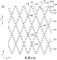
- FIG. 4 is a partial development view for explaining an initial state of the stent shown in FIG. 3.
- FIG. 4 is a partial development view for explaining an expanded state of the stent shown in FIG. 3.
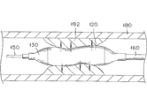
- FIG. 1 is a schematic diagram for explaining a stent delivery system according to an embodiment of the present invention
- FIG. 2 is a schematic diagram for explaining an application of the stent delivery system shown in FIG.
- a stent delivery system 100 is used to improve a stenosis (or occlusion) 182 generated in a lumen 180 in a living body (see FIG. 2), and as shown in FIG.
- the lumen 180 in the living body is, for example, the coronary artery of the heart, and one purpose of placing the stent 120 is to prevent restenosis after percutaneous transluminal coronary angioplasty (PTCA).
- the stent delivery system 100 is not limited to a form applied to a stenosis occurring in the coronary artery of the heart, but can also be applied to a stenosis occurring in other blood vessels, bile ducts, trachea, esophagus, urethra and the like.
- the stent 120 is a medical device that maintains the open state of the lumen 180 by being placed in close contact with the inner surface of the narrowed portion 182 and is configured to be expandable.
- the stent 120 is engaged with the balloon 130, and displacement and separation (separation) of the stent 120 with respect to the balloon 130 are suppressed.
- the stent 120 is configured to ensure uniform expansion, as will be described later.
- the balloon 130 is expandable, and is configured to expand the diameter of the stent 120 disposed on the outer periphery thereof.
- the hub 140 has an injection port 142 and a guide wire port 144.
- the injection port 142 is used, for example, for introducing and discharging a pressurized fluid for expanding the balloon 130.
- the pressurized fluid is, for example, a liquid such as physiological saline or an angiographic contrast agent.
- the guide wire port 144 is used for inserting the guide wire 150 into the shaft tube 160 and projecting from the distal end portion of the shaft tube 160.
- the placement of the stent 120 is performed as follows, for example.
- the distal end portion of the stent delivery system 100 is inserted into the lumen 180 of the patient, and the guide wire 150 that has been protruded from the distal end portion of the shaft tube 160 in advance is positioned on the narrowed portion 182 that is the target site.
- a pressurized fluid is introduced from the injection port 142, and the balloon 130 is expanded to cause expansion and plastic deformation of the stent 120, thereby closely contacting the stenosis 182 (see FIG. 2).
- the pressure of the balloon 130 is reduced, the engagement between the stent 120 and the balloon 130 is released, and the stent 120 is separated from the balloon 130.
- the stent 120 is placed in the narrowed portion 182.
- the stent delivery system 100 from which the stent 120 has been separated is then retracted and removed from the lumen 180.
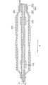
- FIG. 3 is a cross-sectional view for explaining the distal end portion of the stent delivery system shown in FIG.
- the balloon 130 is arranged along the axial direction A on the outer periphery of the tip portion of the shaft tube 160 in a folded state (or a contracted state), and is expandable.
- the stent 120 is disposed on the outer periphery of the balloon 130 in a state where the diameter is reduced. Then, the linear member 122 of the stent 120 is expanded by the expansion of the balloon 130.
- the material forming the balloon 130 is preferably flexible, for example, polyolefin, polyvinyl chloride, polyamide, polyamide elastomer, polyurethane, polyester such as polyethylene terephthalate, polyarylene sulfide such as polyphenylene sulfide, silicone rubber, latex, etc. It is rubber.
- the polyolefin is, for example, polyethylene, polypropylene, ethylene-propylene copolymer, ethylene-vinyl acetate copolymer, or cross-linked ethylene-vinyl acetate copolymer.
- the stent 120 is made of a biocompatible material.
- biocompatible materials are nickel-titanium alloys, cobalt-chromium alloys, stainless steel, iron, titanium, aluminum, tin, and zinc-tungsten alloys.
- the shaft tube 160 has an inner tube 162 and an outer tube 164 into which the inner tube 162 is inserted.
- the inner tube 162 communicates with the guide wire port 144 of the hub 140 and extends through the balloon 130 to the tip. Therefore, the guide wire 150 inserted into the guide wire port 144 can freely protrude from the distal end of the stent delivery system 100, and the inside of the inner tube 162 forms a lumen 161 for the guide wire.
- a cylindrical marker 170 is attached to the outer periphery of the inner tube 162 inside the balloon 130.
- the marker 170 is made of a radiopaque material, and a clear contrast image can be obtained under fluoroscopy, so that the positions of the balloon 130 and the stent 120 can be easily confirmed.
- the radiopaque material is, for example, platinum, gold, tungsten, iridium, or an alloy thereof.
- the outer tube 164 is disposed outside the inner tube 162, and the lumen 163 formed by the space between the inner peripheral surface of the outer tube 164 and the outer peripheral surface of the inner tube 162 is connected to the injection port 142 of the hub 140. Communicate.
- a balloon 130 is fixed in a liquid-tight manner to the outer periphery of the distal ends of the inner tube 162 and the outer tube 164, and the inside of the balloon 130 communicates with the lumen 163. Therefore, the pressurized fluid introduced from the injection port 142 passes through the lumen 163, is introduced into the balloon 130, and the balloon 130 can be expanded.
- the method for fixing the outer peripheral ends of the inner tube 162 and the outer tube 164 to the balloon 130 is not particularly limited, and, for example, an adhesive or heat fusion can be applied.
- the constituent material of the outer tube 164 is preferably flexible, such as polyethylene, polypropylene, polybutene, ethylene-propylene copolymer, ethylene-vinyl acetate copolymer, ionomer, or two or more of these.
- Polyolefins such as a mixture of these, thermoplastic resins such as soft polyvinyl chloride resin, polyamide, polyamide elastomer, polyester, polyester elastomer, polyurethane, fluororesin, silicone rubber, latex rubber.
- the same material as the outer tube 164 or a metal material can be applied.
- the metal material is, for example, stainless steel or Ni—Ti alloy.
- the constituent material of the hub 140 is, for example, a thermoplastic resin such as polycarbonate, polyamide, polysulfone, polyarylate, or methacrylate-butylene-styrene copolymer.
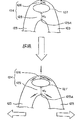
- FIG. 4 and 5 are partially developed views for explaining the initial state (the state in which the diameter is reduced) and the expanded state of the stent shown in FIG. 3, and FIG. 6 is an expanded state of the linear member shown in FIG. It is a conceptual diagram for demonstrating the deformation
- the stent 120 includes a linear member 122 that extends in the circumferential direction C of the stent and can expand and contract in the radial direction.
- the linear members 122 constitute an annular body and are arranged in a plurality in the axial direction A, and the adjacent annular bodies are integrated with each other via a connecting portion 128.
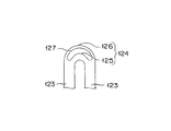
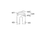
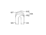
- the linear member 122 is wavy and has a pair of linear portions 123, top portions 124 and 129, and an opening portion 127. Both ends of the top portions 124 and 129 are connected to a pair of linear portions 123.
- the opening 127 is located at least at the tops 124 and 129.
- the top portions 124 and 129 include a link portion 126 that is a portion located on the outer peripheral side of the opening portion 127 and a base portion 125 that is a portion located on the inner peripheral side of the opening portion 127. Note that the openings 127 are preferably provided in all the top portions 124 and 129 of the linear member 122.
- the shape of the opening 127 is an ellipse.
- the linear part 123 is linear over the full length. Note that the linear portion 123 only needs to be linear at least in part, particularly in the vicinity of both ends connected to the top portions 124 and 129. For example, the linear portion 123 may have a curved portion that is gently curved.
- the wavelength W which is the distance between the apexes of the apexes 124, 129 adjacent to each other in the stent circumferential direction C
- the amplitude V which is the distance between the apexes of the apexes 124, 129 located (connected) at both ends of the linear portion 123.
- the thickness of the stent 120 is thin, or the stent is subjected to forces in various directions from the blood vessel wall or the like under actual use. But the impact is limited.
- a force that expands the inner surface of the lumen 180 (stenosis 182) (for example, vascular expansion force). Can be added appropriately (see FIG. 2).
- the inner periphery of the base part 125 is curved, and the link part 126 is arranged so as to straddle the vertex 125A, which is the inflection point of the base part 125, or the outer periphery of the part facing the vertex 125A in the link part 126 is curved It is preferable that In this case, it is possible to effectively exert the spring action of the link portion 126.
- the curvature radius of the outer periphery of the link portion 126 is preferably larger than the curvature radius of the inner periphery of the base portion 125. In this case, the spring action of the link part 126 becomes good, and the plastic deformation of the base part 125 proceeds smoothly. Further, the width W 1 of the link 126 in the circumferential direction C of the stent is preferably smaller than the width W 2 of the base 125 in the circumferential direction C of the base 125 at the apex 125A (see FIG. 6). In this case, the spring action of the link portion 126 is further improved.
- the linear member 122 has a top portion 129 connected to the connecting portion 128 and a top portion 124 not connected to the connecting portion 128. Therefore, since each top part 124,129 becomes easy to deform
- the formation method of the linear member 122 is not particularly limited.
- the outer periphery of the tubular stent material is laser-cut based on the pattern of the linear member 122, or the masking material corresponding to the pattern of the linear member 122 is tubular. It can be formed by arranging and etching the outer periphery of the stent material.
- the shape of the opening 127 is not limited to an ellipse, and may be, for example, a shape obtained by curving the center of an ellipse (see FIG. 7) or a crescent (see FIG. 8).
- the link part 126 is not limited to the form formed integrally with the base part 125 (linear member 122), It is also possible to join the link part 126 formed as a separate body to the base part 125 (top part 124). is there.
- the opening 127 can be configured to extend beyond the top portion 124 to the linear portion 123 as necessary. In this case, the end portion of the link portion 126 is connected to the linear portion 123. Will do.
- the balloon catheter is not limited to the over-the-wire (OTW) type, but can be applied to a rapid exchange (RX) type.
- OW over-the-wire
- RX rapid exchange
- the stent from a biodegradable polymer that can be decomposed and absorbed in vivo over time, or to coat the stent surface with a drug (bioactive substance).
- the biodegradable polymer is, for example, polylactic acid, polyglycolic acid, or a copolymer of lactic acid and glycolic acid.
- the drug is, for example, an anticancer agent, an immunosuppressive agent, an antibiotic, an immunosuppressive agent, or an antithrombotic agent.
- a marker on the base side of the shaft tube.
- 100 stent delivery system 120 stent, 122 linear member, 123 linear part, 124,129 top, 125 base, 125A vertex, 126 link part, 127 opening, 128 connecting parts, 130 balloon, 140 hub, 142 injection port, 144 Guide wire port, 150 guide wire, 160 Shaft tube (shaft part), 161 lumens, 162 inner pipe, 163 lumens, 164 outer tube, 170 markers, 180 lumens, 182 Stenosis, A axis direction, C circumferential direction, V amplitude, W wavelength, W 1 , W 2 width.
Landscapes
- Health & Medical Sciences (AREA)
- Engineering & Computer Science (AREA)
- Biomedical Technology (AREA)
- Heart & Thoracic Surgery (AREA)
- Cardiology (AREA)
- Oral & Maxillofacial Surgery (AREA)
- Transplantation (AREA)
- Vascular Medicine (AREA)
- Life Sciences & Earth Sciences (AREA)
- Animal Behavior & Ethology (AREA)
- General Health & Medical Sciences (AREA)
- Public Health (AREA)
- Veterinary Medicine (AREA)
- Optics & Photonics (AREA)
- Physics & Mathematics (AREA)
- Media Introduction/Drainage Providing Device (AREA)
Abstract
Priority Applications (5)
| Application Number | Priority Date | Filing Date | Title |
|---|---|---|---|
| CN201280003902XA CN103237527A (zh) | 2011-03-29 | 2012-03-07 | 支架和支架输送系统 |
| EP12762801.4A EP2692314B1 (fr) | 2011-03-29 | 2012-03-07 | Endoprothèse et système de pose de l'endoprothèse |
| JP2013507322A JP6120373B2 (ja) | 2011-03-29 | 2012-03-07 | ステントおよびステントデリバリーシステム |
| BR112013023320A BR112013023320A2 (pt) | 2011-03-29 | 2012-03-07 | stent e sistema de stent |
| US14/035,136 US9855159B2 (en) | 2011-03-29 | 2013-09-24 | Stent and stent delivery system |
Applications Claiming Priority (2)
| Application Number | Priority Date | Filing Date | Title |
|---|---|---|---|
| JP2011-072476 | 2011-03-29 | ||
| JP2011072476 | 2011-03-29 |
Related Child Applications (1)
| Application Number | Title | Priority Date | Filing Date |
|---|---|---|---|
| US14/035,136 Continuation US9855159B2 (en) | 2011-03-29 | 2013-09-24 | Stent and stent delivery system |
Publications (1)
| Publication Number | Publication Date |
|---|---|
| WO2012132801A1 true WO2012132801A1 (fr) | 2012-10-04 |
Family
ID=46930547
Family Applications (1)
| Application Number | Title | Priority Date | Filing Date |
|---|---|---|---|
| PCT/JP2012/055774 Ceased WO2012132801A1 (fr) | 2011-03-29 | 2012-03-07 | Endoprothèse et système de pose de l'endoprothèse |
Country Status (6)
| Country | Link |
|---|---|
| US (1) | US9855159B2 (fr) |
| EP (1) | EP2692314B1 (fr) |
| JP (1) | JP6120373B2 (fr) |
| CN (1) | CN103237527A (fr) |
| BR (1) | BR112013023320A2 (fr) |
| WO (1) | WO2012132801A1 (fr) |
Families Citing this family (4)
| Publication number | Priority date | Publication date | Assignee | Title |
|---|---|---|---|---|
| US9011511B2 (en) * | 2009-02-20 | 2015-04-21 | Boston Scientific Scimed, Inc. | Balloon catheter |
| US10849769B2 (en) * | 2017-08-23 | 2020-12-01 | Vesper Medical, Inc. | Non-foreshortening stent |
| CN114533355A (zh) * | 2020-11-19 | 2022-05-27 | 上海鸿脉医疗科技有限公司 | 一种医用支架 |
| US20250058539A1 (en) * | 2021-12-20 | 2025-02-20 | Kool Global Solutions Pty Ltd | Apparatus for forming a blank |
Citations (7)
| Publication number | Priority date | Publication date | Assignee | Title |
|---|---|---|---|---|
| JP2000084090A (ja) * | 1998-09-09 | 2000-03-28 | Kawasumi Lab Inc | ステント |
| JP2000516486A (ja) | 1996-08-02 | 2000-12-12 | ローカルメッド インコーポレイテッド | 優れた拡大特性および画像特性を有する管状プロテーゼ |
| JP2004329790A (ja) * | 2003-05-12 | 2004-11-25 | Nipro Corp | 血管追従性・管腔径保持性の優れた柔軟なステント |
| US20050283228A1 (en) * | 1998-07-29 | 2005-12-22 | Stanford Ulf H | Expandable stent with relief holes capable of carrying medicines and other materials |
| US20090204202A1 (en) * | 2008-02-08 | 2009-08-13 | William Cook Australia Pty. Ltd. | Stent designs for use with one or more trigger wires |
| JP2009240796A (ja) * | 2001-09-11 | 2009-10-22 | Xtent Inc | ステント |
| JP2009240613A (ja) * | 2008-03-31 | 2009-10-22 | Terumo Corp | 生体内留置用ステントおよび生体器官拡張器具 |
Family Cites Families (5)
| Publication number | Priority date | Publication date | Assignee | Title |
|---|---|---|---|---|
| FR2764794B1 (fr) * | 1997-06-20 | 1999-11-12 | Nycomed Lab Sa | Dispositif tubulaire expanse a epaisseur variable |
| CA2241558A1 (fr) * | 1997-06-24 | 1998-12-24 | Advanced Cardiovascular Systems, Inc. | Tuteur avec montants de renforcement et deploiement bimodal |
| US20010032011A1 (en) * | 1999-07-20 | 2001-10-18 | Stanford Ulf Harry | Expandable stent with array of relief cuts |
| US7014654B2 (en) | 2001-11-30 | 2006-03-21 | Scimed Life Systems, Inc. | Stent designed for the delivery of therapeutic substance or other agents |
| WO2007005800A1 (fr) * | 2005-06-30 | 2007-01-11 | Abbott Laboratories | Endoprotheses comprenant des pieds de prolongement |
-
2012
- 2012-03-07 WO PCT/JP2012/055774 patent/WO2012132801A1/fr not_active Ceased
- 2012-03-07 JP JP2013507322A patent/JP6120373B2/ja not_active Expired - Fee Related
- 2012-03-07 BR BR112013023320A patent/BR112013023320A2/pt not_active Application Discontinuation
- 2012-03-07 EP EP12762801.4A patent/EP2692314B1/fr active Active
- 2012-03-07 CN CN201280003902XA patent/CN103237527A/zh active Pending
-
2013
- 2013-09-24 US US14/035,136 patent/US9855159B2/en not_active Expired - Fee Related
Patent Citations (7)
| Publication number | Priority date | Publication date | Assignee | Title |
|---|---|---|---|---|
| JP2000516486A (ja) | 1996-08-02 | 2000-12-12 | ローカルメッド インコーポレイテッド | 優れた拡大特性および画像特性を有する管状プロテーゼ |
| US20050283228A1 (en) * | 1998-07-29 | 2005-12-22 | Stanford Ulf H | Expandable stent with relief holes capable of carrying medicines and other materials |
| JP2000084090A (ja) * | 1998-09-09 | 2000-03-28 | Kawasumi Lab Inc | ステント |
| JP2009240796A (ja) * | 2001-09-11 | 2009-10-22 | Xtent Inc | ステント |
| JP2004329790A (ja) * | 2003-05-12 | 2004-11-25 | Nipro Corp | 血管追従性・管腔径保持性の優れた柔軟なステント |
| US20090204202A1 (en) * | 2008-02-08 | 2009-08-13 | William Cook Australia Pty. Ltd. | Stent designs for use with one or more trigger wires |
| JP2009240613A (ja) * | 2008-03-31 | 2009-10-22 | Terumo Corp | 生体内留置用ステントおよび生体器官拡張器具 |
Also Published As
| Publication number | Publication date |
|---|---|
| JP6120373B2 (ja) | 2017-04-26 |
| US9855159B2 (en) | 2018-01-02 |
| EP2692314A1 (fr) | 2014-02-05 |
| EP2692314A4 (fr) | 2014-10-15 |
| EP2692314B1 (fr) | 2019-01-09 |
| CN103237527A (zh) | 2013-08-07 |
| JPWO2012132801A1 (ja) | 2014-07-28 |
| BR112013023320A2 (pt) | 2016-12-13 |
| US20140025153A1 (en) | 2014-01-23 |
Similar Documents
| Publication | Publication Date | Title |
|---|---|---|
| EP1366732B1 (fr) | Système de mise en place d'un stent avec un fil-guide fixe | |
| JP6479493B2 (ja) | 高柔軟性ステント | |
| JP4976301B2 (ja) | 脈管分枝部治療用段付きバルーンカテーテル | |
| US7691137B2 (en) | Rotatable sheath, assembly and method of manufacture of same | |
| US9056157B2 (en) | Hybrid biodegradable/non-biodegradable stent, delivery system and method of treating a vascular condition | |
| US20070021819A1 (en) | Apparatus and Methods for Locating an Ostium of a Vessel | |
| JP2010523222A (ja) | バルーンの再折り畳みを促進する内部機構を有するカテーテル | |
| JP2008541835A (ja) | 繊維メッシュで制御される拡張バルーンカテーテル | |
| JP2018068724A (ja) | バルーンカテーテル | |
| JP6120373B2 (ja) | ステントおよびステントデリバリーシステム | |
| JP7029578B1 (ja) | ステント | |
| JP2009082244A (ja) | 生体内留置用ステントおよび生体器官拡張器具 | |
| US10251765B2 (en) | Stent delivery system and manufacturing method for the same | |
| CN115515656A (zh) | 具有改进的医疗装置保持的医疗装置传输系统 | |
| JP5847160B2 (ja) | ステントおよびステントデリバリーシステム | |
| JP5797918B2 (ja) | ステントデリバリーシステムおよびその製造方法 | |
| JP5770507B2 (ja) | 自己拡張型ステントおよびステントデリバリーシステム | |
| JP2018079142A (ja) | ステントデリバリーシステム | |
| JP2024099893A (ja) | ステントデリバリーシステム | |
| JP2015077156A (ja) | 生体内留置物デリバリーシステム | |
| HK1242172A1 (en) | Highly flexible stent | |
| HK1223814B (en) | Highly flexible stent |
Legal Events
| Date | Code | Title | Description |
|---|---|---|---|
| 121 | Ep: the epo has been informed by wipo that ep was designated in this application |
Ref document number: 12762801 Country of ref document: EP Kind code of ref document: A1 |
|
| ENP | Entry into the national phase |
Ref document number: 2013507322 Country of ref document: JP Kind code of ref document: A |
|
| WWE | Wipo information: entry into national phase |
Ref document number: 2012762801 Country of ref document: EP |
|
| NENP | Non-entry into the national phase |
Ref country code: DE |
|
| REG | Reference to national code |
Ref country code: BR Ref legal event code: B01A Ref document number: 112013023320 Country of ref document: BR |
|
| ENP | Entry into the national phase |
Ref document number: 112013023320 Country of ref document: BR Kind code of ref document: A2 Effective date: 20130911 |