WO1991008520A1 - Procede et appareil de traitement d'images couleur - Google Patents
Procede et appareil de traitement d'images couleur Download PDFInfo
- Publication number
- WO1991008520A1 WO1991008520A1 PCT/JP1990/001568 JP9001568W WO9108520A1 WO 1991008520 A1 WO1991008520 A1 WO 1991008520A1 JP 9001568 W JP9001568 W JP 9001568W WO 9108520 A1 WO9108520 A1 WO 9108520A1
- Authority
- WO
- WIPO (PCT)
- Prior art keywords
- dot area
- area ratio
- color
- quaternary
- colors
- Prior art date
- Legal status (The legal status is an assumption and is not a legal conclusion. Google has not performed a legal analysis and makes no representation as to the accuracy of the status listed.)
- Ceased
Links
Classifications
-
- G—PHYSICS
- G06—COMPUTING OR CALCULATING; COUNTING
- G06T—IMAGE DATA PROCESSING OR GENERATION, IN GENERAL
- G06T1/00—General purpose image data processing
-
- H—ELECTRICITY
- H04—ELECTRIC COMMUNICATION TECHNIQUE
- H04N—PICTORIAL COMMUNICATION, e.g. TELEVISION
- H04N1/00—Scanning, transmission or reproduction of documents or the like, e.g. facsimile transmission; Details thereof
- H04N1/46—Colour picture communication systems
- H04N1/56—Processing of colour picture signals
- H04N1/60—Colour correction or control
- H04N1/603—Colour correction or control controlled by characteristics of the picture signal generator or the picture reproducer
-
- H—ELECTRICITY
- H04—ELECTRIC COMMUNICATION TECHNIQUE
- H04N—PICTORIAL COMMUNICATION, e.g. TELEVISION
- H04N1/00—Scanning, transmission or reproduction of documents or the like, e.g. facsimile transmission; Details thereof
- H04N1/46—Colour picture communication systems
- H04N1/56—Processing of colour picture signals
- H04N1/60—Colour correction or control
- H04N1/6016—Conversion to subtractive colour signals
- H04N1/6022—Generating a fourth subtractive colour signal, e.g. under colour removal, black masking
-
- Y—GENERAL TAGGING OF NEW TECHNOLOGICAL DEVELOPMENTS; GENERAL TAGGING OF CROSS-SECTIONAL TECHNOLOGIES SPANNING OVER SEVERAL SECTIONS OF THE IPC; TECHNICAL SUBJECTS COVERED BY FORMER USPC CROSS-REFERENCE ART COLLECTIONS [XRACs] AND DIGESTS
- Y10—TECHNICAL SUBJECTS COVERED BY FORMER USPC
- Y10S—TECHNICAL SUBJECTS COVERED BY FORMER USPC CROSS-REFERENCE ART COLLECTIONS [XRACs] AND DIGESTS
- Y10S347/00—Incremental printing of symbolic information
- Y10S347/90—Data processing for electrostatic recording
Definitions
- the dot area ratio when performing color printing using four color inks of yellow (Y), magenta (M), cyan (C) and black (K) is determined by a color scanner or the like.
- the present invention relates to an image processing method and apparatus.
- the dot area ratio of the three colors of ⁇ M C C is obtained as described above, and the minimum value thereof is multiplied by the black ratio to obtain the dot area ratio of ⁇ . Then, the area ratio of ⁇ is subtracted from the area ratio of YMC for the addition of the ink, and this is defined as the dot area ratio of YMC.
- the method based on the above method is based on the concept of color mixing in the conventional method, so if it is applied directly to the area modulation method that expresses color by changing the amount of halftone dots, Good color reproduction cannot be achieved.
- the present invention provides a color image processing method and apparatus for determining the dot area ratio of each of the YMCK inks that achieves the target color correctly with a color scanner, a color scanner, or the like. Aim.
- Z f z (AT, AM , AC, AK) ... (A1) '.
- Ay, Am, Ac,... are the 16 color points (w (paper),, m, c, k, ym, yc, mc, yk, mk, ck, ymk, yck, mck, ymc, ymck).
- ⁇ , Y, Zw, Xy, Yy, Zy, Xm, Ym, Zm, Xc, Yc, Zc,... are the tristimulus values for each of the above color points. Obtained by actual measurement from paper.
- a mck (1-A T ) A u A c AK
- Aymck A ⁇ A U A C A K (A 2)
- the above quaternary fourth-order Neugebauer equation Based on this, the dot area ratio for accurately reproducing the tristimulus values X, Y, and Z of the target color is determined by the method described later.
- FIG. 1 and 3 are processing flowcharts showing the processing procedure of each embodiment of the present invention
- FIG. 2 is a diagram showing 16 kinds of color points
- FIG. 4 is a diagram of a color image processing apparatus of the present invention. It is a block diagram of an Example.
- 3 A U , 3 A c are One 3 AT one
- FIG. 1 is a processing flow chart showing the processing procedure of this embodiment.
- the dot area ratio for reproducing the target color in three colors of YMC without adding black ink is calculated.
- a T, A «, initial area coverage A TD of A c, Aun, A c. Is defined as an approximation given by the complementary color relation in consideration of the distribution of ( ⁇ ), y ( ⁇ ), of the X, Y, and ⁇ color matching functions (Fig. 1 S
- a T3 A TO — d A T
- a Ma A «o-d A M
- a c 3 A co— d A c (A 1 0)
- differential correction obtaining the dot area by the method using differentiation as described above.
- the dot area ratios A T3 , A M3 , and A C3 were obtained as described above. However, since the dot area ratios A T3 , A «3, ⁇ are obtained as the dot area ratios when the target color is reproduced with three colors of YMC, the YMCK Calculate the dot area ratio that reproduces the target color by color.
- ⁇ ⁇ * K 1 X ⁇ ( ⁇ ⁇ 3, A M3 , A C3 )
- K t Ink ratio (All) (Fig. 1, S3). That is , the minimum value of the dot area ratios A T3 , ⁇ ⁇ 3 , and A C3 multiplied by the ink ratio is defined as the dot area ratio ⁇ ⁇ ⁇ 4 . However, if A K4 exceeds 0.9 (Fig. 1. S 4),
- ⁇ ⁇ 4 ( ⁇ ⁇ 3-0.95 ⁇ ⁇ 4) / (1-0.95 ⁇ ⁇ 4)
- ⁇ «4 ( ⁇ ⁇ 3 -0.95 ⁇ ⁇ 4) / (1-0.95 ⁇ ⁇ 4)
- a c4 (A C3-0.95A K4) / (1-0.95A K4)
- AK4 is a constant.
- a K4 is multiplied by a constant 0.95, but this constant is not limited to 0.95, and may be any value in the range of 0.9 to 1.0. The same applies hereinafter.
- a ⁇ 4 ' A T4-a A ⁇
- the differential correction may be performed several times thereafter.
- the initial dot area ratio at that time uses the dot area ratio obtained by the previous differential correction. Then this way dot percent Alpha .tau.4 determined ', ⁇ ⁇ 4', when there is negative in the A c (FIG. 1 S 8), the A K4 ⁇ ⁇ ', AU * ' , A c, the value of the negative one is added, and the negative one is zero (S 9 in Fig. 1).
- a K4 becomes negative in this process (S 10 in FIG. 1), A K4 is also set to zero (S 11 in FIG. 1).
- the dot area ratio of YMC Y determined as described above is the dot area ratio that correctly reproduces the target color.
- the amount of black can be adjusted by changing the value of the black ratio Ki, as shown by the expression (A11).
- FIG. 3 is a processing flowchart showing the processing procedure of the present embodiment.
- ⁇ ⁇ ⁇ (1- ⁇ ) -0.95 ⁇ ⁇ ⁇ / (1-0.95 ⁇ ⁇ )
- ⁇ ⁇ 0 ⁇ (1- ⁇ ) -0.95 ⁇ ⁇ ⁇ / (1-0.95 ⁇ ⁇ )
- a co ((1- ⁇ ) -0.95 ⁇ ⁇ ⁇ ⁇ / (1-0.95 ⁇ ⁇ )
- ⁇ ⁇ is A ⁇ first. Fixed to
- a T3 A TO-d A T
- a C3 A co-d A c
- a T3 , A M3 , Aca, and A K3 in the expression (A 16) are used as the initial dot area ratios, and the above-described differential correction is performed again, and the higher accuracy ⁇ ⁇ A T3 , Au3, A C3, You can also ask for A K3 .
- the dot area ratio is set to zero, and the other two and A X3 are initialized. Repeat the derivative correction for the point area ratio an appropriate number of times (for example, three times).
- a K3 is the minimum
- a K3 is set to 1
- a T3 , A U3 , and A C3 are set as the initial dot area ratios, and the differential correction is repeated an appropriate number of times (Fig. 3, S4). The details will be described later.
- a U3 0
- a cs, ⁇ ⁇ 3 are used as initial dot area ratios, and differential correction is repeated an appropriate number of times to determine the dot area ratios of A M , A c, ⁇ ⁇ .
- Equations (A5) and (A17) are expressed in a matrix for MCK,
- a C3 0, A T3, A U3, A ⁇ 3 as the initial area coverage repeating appropriate times the differential correction the, ⁇ ⁇ , ⁇ ⁇ , the Alpha kappa Obtain the dot area ratio.
- Alpha kappa 3 1 and then, A T3, A U3, A C3 as the initial area coverage repeating appropriate times the differential correction the, A T, A u, obtains the dot area percent of A c.
- a A ⁇ , d A 3 A C can be obtained, and from this, the dot area ratio of YMC is obtained.
- the halftone dot area ratio of YMCK obtained as described above is a halftone dot area ratio that correctly reproduces the target color.
- the YMCK halftone dot area ratio is determined so that black is applied to the maximum when a certain target color is reproduced.
- the color difference between the reproduced color obtained by the determined halftone dot surface ratio and the target color for example, ⁇ in the CIELAB color system
- the differential correction may be performed a required number of times again to determine the dot area ratio again.
- the halftone dot area ratio determined by this processing will reproduce the target color with higher accuracy.
- FIG. 4 is a block diagram of an embodiment of the color image processing apparatus of the present invention for determining a dot area ratio from a color signal obtained by scanning a document with a scanner.
- Reference numeral 1 denotes an input device for inputting a color signal of the original by separating and scanning the original with a scanner, or inputting data stored in a magnetic tape or the like after being converted into a color signal by another device.
- 1 2 is the input data memory, which is input from the input device 1 1
- the stored color signal data is stored.
- the color conversion unit 13 is a color conversion unit.
- the color conversion unit converts the color signals from those color systems to the XYZ color system. Convert to color signal.
- each L coefficient expressed by the formula (A) is calculated and obtained, and the value is stored.
- Reference numeral 15 denotes a halftone dot area ratio calculation unit, which calculates the tristimulus values X, Y, ⁇ of the target color and the tristimulus values of each color point stored in the memory 14 or the value of each L coefficient.
- the dot area ratio is calculated by the method of each embodiment described above.
- Reference numeral 16 denotes a color difference calculating unit which calculates a color difference between a reproduced color obtained by the dot area ratio calculated by the dot area ratio calculating unit 15 and a target color.
- a color difference calculating unit which calculates a color difference between a reproduced color obtained by the dot area ratio calculated by the dot area ratio calculating unit 15 and a target color.
- Reference numeral 17 denotes output data memory for storing the determined dot area ratio.
- the halftone dot ridge ratio for reproducing the target color is determined for each pixel.
- each color plate 18 of YMCK can be created and printed using it to obtain a desired printed matter 19.
- the present invention determines the dot area ratio at the time of color printing, but the present invention is not limited to only the case of color printing.
- the number of times of the differential correction in each of the above steps is not limited to the above.
- the present invention is based on the Neugebauer method which accurately describes the actual phenomenon that four color printing of YMCK ink is reproduced by average additive color mixing of 16 kinds of color points. Since the halftone dot area ratios of the four colors including black are determined based on the formula, there is an effect that good color reproduction can be performed.
Landscapes
- Engineering & Computer Science (AREA)
- Multimedia (AREA)
- Signal Processing (AREA)
- Physics & Mathematics (AREA)
- General Physics & Mathematics (AREA)
- Theoretical Computer Science (AREA)
- Facsimile Image Signal Circuits (AREA)
- Color Image Communication Systems (AREA)
Description
明 細 書
カラー画像処理方法および装置
技 術 分 野
本発明は、 イエロ一 ( Y ) 、 マゼンタ ( M ) 、 シアン ( C ) 、 墨 ( K ) の四色のイ ンキを使ってカラ一印刷を する際の網点面積率をカラースキャナなどで決定する力 ラー画像処理方法および装置に関するものである。
背 景 技 術
カラー印刷は、 原則的には Y M Cイ ンキの三色の重ね 刷りで大部分の色を印刷することができる。
しかし三色の重ね刷りでは、
① . インキが重なった部分の トラッ ピングが悪い
② . 良好な黒が再現できない
③ . 同一個所に最大三色のイ ンキが重なるこ と になるた め、 イ ンキの使用量が多く、 経済的でない
④ . コン トラス トが低い
などの問題がある。
そ こで一般には、 Y M Cイ ンキに墨 ( K ) イ ンキを加 えた四色でカラー印刷を行って上記問題を解決しょう と している。
しかし墨を加えた四色でカラ一印刷を行う場合、 目標 色を再現するための各色の網点面積率を決定するのが難 し く 、 かつ従来方法で決定した網点面積率で印刷しても 必ずしも良好な色再現ができないという問題がある。
例えば従来よ り網点面積率を決定する 1つの方法と し て、 下記に示すマスキング方程式に、 再現しょう とする

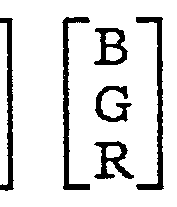
こ こで [ a *»] ( £ , = 1 , 2 , 3 ) はマスキング 係数と呼ばれるパラメータである。 このパラメータ を適 切に定めて、 Y M C三色の網点面積率と している。
Y M C K四色の場合は、 いったん上述のよう に して Υ M C三色の網点面積率を求め、 その中の最小値に墨率を 乗じてそれを Κの網点面積率と している。 そして墨を加 えた分、 Y M Cの面積率から Κの面積率を減じ、 それを Y M Cの網点面積率と している。
しかし上記方法によるものは、 従来写真における减法 混色を中心と した考えのもとになされたものであるため 網点の面積量を変えて色を表現する面積変調方式のもの にそのまま適用 した場合、 良好な色再現ができない。
その上、 墨インキが加わることによ り、 更に良好な色 再現が難し く なるという問題がある。
本発明は以上の点から成したものでぁ リ、 カラースキ ャナなどで目檫色を正し く再現する Y M C K各インキの 網点面積率を決定するカラー画像処理方法および装置を 提供すること を 目的とする。
発 明 の 開 示
はじめに本発明の原理を説明する。
紙の上に Y M C K四色のインキで網点印刷すると きに 得られる再現色の、 X Y Z表色系における三剌激値 X,
Y , Zは、 下記のノィゲバウア方程式(Neugebauer
Equation)によ リ得られる。
X = AwXw+ AyXy+ AmXm+ AcXc+ AkXk +
A ym X ym + A yc X yc + A mc X mc + A yk X yk +
A mkX mk+ A ckX ck+ A ymk X ymk +
AyckXyck+ AmckXmck + A ymc X ymc +
A ymck X ymck
Y = AwY w+ AyYy+ AmY m+ AcY c+ AkYk +
A ym Y ym + A yc Y yc + A mc Y mc + A yk Y yk +
Amk Y mk+ AckY ck+ AymkY ymk +
AyckY yck + AmckY mck + A ymc Y ymc +
A ymck Y ymck
Z = AwZ + AyZ y+ AmZ m+ AcZ c+ Ak Zk +
A ym Z ym + A yc Z yc + A mc Z mc + A yk Z yk +
A mk Z mk + A ck Z ck + A ymk Z ymk +
A yck Z yck + A mck Z mck + A ymc Z ymc +
A ymck Z ymck
…… ( A 1 )
このノィゲバウア方程式を簡単な関数の式で表わすと、
X = f X ( A T , A U, A C, A K)
Y = f T ( A T , Aut Ac, A K)
Z = f z ( A T , A M, A C, A K) … ( A 1 ) ' となる。
こ こで Ay, Am, Ac, …, は第 2図に示す 1 6種類 の色点 ( w (紙), , m , c, k, y m , y c , m c, y k , m k , c k , y m k , y c k , m c k , y m c , y m c k ) の面積率である。
また Χβ, Y , Z w, Xy, Yy, Zy, Xm, Y m, Zm, Xc, Y c, Zc, …, は上記各色点の三刺激値であ り、 印刷に使用する Y M C Kのインキと紙から実測して得ら れる。
また各色点の面積率は Y M C Kイ ンキの網点面積率を A T, Ait, Ac, Axとすると、 デミ ッシェルの関係から 下式で与えられる。
Aw = (1- AT)(1- Au)(l- Ac)(l- Ακ)
Ay = AT(1- AH) (1- Ac) (1- Ακ)
Am = (1- A T) AM (1- Ac) (1- A K)
Ac = (1- AT)(1- Au) Ac(l- AK)
Ak = (1- AT) (1- Au)(1- A C) AK

Amc = (1- A T) AiiA c(l- A K)
Ayk = AT(1- AM) (1— Ac) A K
Ank = (1一 AT) AM(1— Ac) AK

A mck = (1一 A T) A u A c A K

Aymck= A τ AUA CA K ( A 2 )
この (A 2 ) 式を (A l ) 式に代入する と、
X = ( L xi - L ι' A κ) 一 ( L χ2 - L χ2' Α κ) Α τ -
( L a - L xa' A κ) A M - ( L x4 - L x4' A K) A c +
( L XB - L X6' A K) A T A M +
( L 6 - L x6' A K) A T A c +
( L - L x7' A K) A « A c-
( L xe - L e' A x) A T A M A c ( A 3 )
( Y , Zも同型のため省略する)
となる。 ただし、

L Xz = X w— X y
L E' = X w- Xy- Xk+ Xyk
L x s = X w— X m
L x8' = Xw- Xm- Xk+ Xmk
L 4 = X w- Xc
L x4' = Xw- Xc- Xk+ ck
L 6 = Xw— Xy— Xm + Xym
L xB' = Xw- Xy- Xm- Xk+ Xym+ k+ rak- Xymk L x6 = X w- Xy- Xc+ Xyc
Lx6' = Xw- Xy- Xc- Xk+ Xyc+ yk+ ck- Xyck L x 7 = Xw— Xm— Xc + Xmc
L x7' = Xtf- Xm- Xc- Xk+ mc+ mk+ ck- mck
L Χβ = Xw- Xy- XB- Xc+ Xya+ yc+ mc- X ync L xe' = X w- X y- X m- Xc— Xk+ X ym+ Xyc+ Xmc +
Xyk+ X mk- X ck- X ymk - X yck - X mck-
X ymc + X yiack
L T i = Y w
L Ti' = Y - Y k
L T z = Y w— Y y
L Τ Ϊ' = Y w— Y y— Y k+ Yyk
L T a = Y w— Y m
L Τ8' = Y w— Y BJ— Yk+ Y Bik
L T 4 = Y - Y c
L T*' = Y w— Y c— Y k+ Y ck
L T 6 = Y - Y y- Y B+ Y ym
L T5' = y w- Y y- Y m- Yk+ Yym+ Y yk+ Ymk- Yyink L T 6 = Y w- Y y- Y c+ Y yc
L T6' = Y w- Y y- Y c- Y k+ Y yc+ Yyk+ Y ck- Yyck L T 7 = Y W- Y B- Y C+ Y DIC
L T 7' = Y w~- Ym- Y c- Y k+ Ymc+ YBk+ Yck- Ynick L T8 = Y w- Y y- Y jn- Y c+ Yyn+ Yyc+ Yinc- Y yjnc L Te' = Yw- Yy- YB- y c- Yk+ Yym+ Yyc+ Ymc-|-
Y yk+ Y mk+ Y ck - Y ymk - Y yck - Y nick-
Y yac + Y yack
L z l = Z w
L Z1' = Z w- Z k
L zz = Z w - Z y
L zz' - Z w- Z y - Z k+ Z yk
L z 8 = Z w— Z m
L Z8' = Z w - Z m- Z k+ Z mk
L Z4 = Z w- Z c
L z4' = Z w- Z c- Z k+ Zck
L z 6 = Z w- Z y- Z m+ Z ym
L Z6' = Z w— Z y— Z m— Z k + Z ym+ Z yk+ Z mk— Z ymk L Z 6 = Z w- Z y- Z c+ Z yc
L Z6' = Z w— Z y— Z c— Z k + Z yc+ Z yk + Z ck— Z yck L z 7 = Z w— Z m— Z c + Z mc
L z?' = Z w— Z m— Z c— Z k + Z mc + Z mk+ Z ck— Z mck L z 8 = Z w— Zy— Z m— Z c + Z ym + Z yc + Z mc— Z ymc L ΖΘ' = Z w— Z y— Zm— Z c— Z k+ Z yn+ Z yc+ Z mc +
Z yk+ Z mk + Z ck— Z ymk— Z yck - Z mck -
Z ymc + Z ymck ( A 4 ) である。 以下この ( A 4 ) 式で表わす各 のこ と を L係数と呼ぶことにする。
上記 (A 3 ) 式を A T , A U, A C, A Kについて求めれ ば、 再現する 目擦色の三刺激値 X, Y , Zが与えられた ときの、 Y M C Kインキの網点面積率を決定することが できる。
しかし上記 ( A 3 ) 式は四元四次方程式なので、 通常 の方法では網点面積率 A T, A U, A C, A Kを求めるこ と ができない。
そこで本発明では上記四元四次のノィゲバウア方程式
を基礎と し、 後述する方法で目標色の三刺激値 X , Y , Z を正確に再現するための網点面積率を決定する。
図 面 の 簡 単 な 説 明
第 1 図、 第 3図は本発明の各実施例の処理手順を示す 処理フロー図、 第 2図は 1 6種類の色点を示す図、 第 4 図は本発明のカラ一画像処理装置の実施例のブロ ック図 である。
発明を実施するための最良の形態
まず (A 3 ) 式で与えられるノィゲバウア方程式を A T , A u, A cについて偏微分し、 それぞれ下記のよう に m Xi , A 2 * m a , ± , m Y 2 > m Y 3 , m Z x , m Z 2 f m Z 3と置く と、
~ (L z-L z' AK)+ (Lx6-Lx6' AK) A«

+ (Lxe -Lx6 ' AJ AC+ ^XB一し X8 , AK) AMAC ax
- (Lx3 -Lx3 ' AK)+ (LX6-LX6' AK) AT + (Lx7 -Lx7 ' Ax) Ac+ (Lx8 -Lx8 ' AK) ATA, mX3=- ax
a Ac - (LX4-LX4' Ax) + (し Jts一し Xs ' Ax) AT
+ (し 3l7 - ίχ7 ' Ακ) AM+ (LX8 -LX8 ' AK) AT AM
( Y , zも同型) … ( A 5 ) のよう になる。 従って三剌激値: X Y Z の镉移量 d X

3 A U , 3 A cは、
一 3 AT一
dAc _ …… ( A 7 )

と表わすことができる。
はじめに本発明のカラ一画像処理方法の第一の実施例 を説明する。
第 1 図は本実施例の処理手順を示す処理フロー図であ る。
まず墨を入れずに、 Y M C三色で目標色を再現する と きの網点面積率を求める。
はじめに網点面積率を求めるにあたり、 任意の初期網 点面積率を与える 。 本実施例では、 A T, A«, A cの初 期網点面積率 A TD , Aun , A c。を、 X, Y, Ζ等色関数 の (λ ), y (λ), の分布を考慮して補色関係か ら与えられる近似と して下記のよ う に定める (第 1 図 S
1 ) ο
Α το = 1 - Ζ
A«o = 1 - Y
A co = 1 -
( Α κ0 = 0 ) …… ( A 8 )
初期網点面積率 A T。, Au。, A co ( A κ。) によって 再現される色の三刺激値を: X。, Y。 Ζ。と して目標色 との差は、
0 = 0一 X
5 Υ = Υ 0 - Υ
3 Ζ = Ζ。一 Ζ ( A 9 )
の形で表わされる。 尚、 再現される色の三刺激値 x0,
Y。, Z。は、 初期網点面積率 A T。, Auo , A co , A K。を ノィゲバウア方程式 (A 3 ) 式に入れれば求められる。 次に (Α 8 ) 式で求めた値を (Α 5 ) 式に代入して求 めた値と、 (Α 9 ) 式で求めた値を (Α 7 ) 式に代入す ると、 網点面積率の僞移量 3 ΑΤ, d Au, 3 A Cを求め ることができる。
従って、 目標色に収束させた Y M Cの網点面積率は、
A T3 = A TO — d A T
A Ma = A «o - d A M
A c3 = A co— d A c ( A 1 0 )
で求め られる (第 1 図 S 2 ) 。
本発明では、 上述のよう に微分を用いた手法で網点面 積率を求めることを微分補正と呼ぶ。
以上のよう にして網点面積率 A T3, AM3, A C3が求め られた。 しかしこの網点面積率 A T3 , A «3 , Α は、 Y M C三色で目標色を再現するときの網点面積率と して求 めたものであるため、 次に墨を加えた Y M C K四色で目 標色を再現する網点面積率を求める。
まず Kの網点面積率を、
Α κ* = K 1 X Ηίη( Α τ3 , AM3, A C3 )
K t : 墨率 ( A l l ) とする (第 1 図 S 3 ) 。 つま り網点面積率 A T3, ΑΜ3, A C3の最小値に墨率 を乗じたものを Κの網点面積率 Α Κ4とする。
ただし AK4が 0 . 9 を越えた場合は (第 1.図 S 4 ) 、
Α χ4 = Α κ -20(Α κ4-0.9)2 …… ( A 1 2 )
の演算を行い、 墨の網点面積率を少し減らす (第 1 図 S 5 ) 。
以上のよう にして A κ<が求まったら、 Y M C K四色の 場合の初期網点面積率を、
Α τ4 = (Α τ3-0.95Α κ4)/(1-0.95Α κ4)
Α«4 = (ΑΜ3-0.95Α κ4)/(1-0.95Α κ4 )
A c4 = (A C3-0.95A K4)/(1-0.95A K4 )
Ακ* …… ( A 1 3 ) と し (第 1 図 S 6 ) 、 微分補正を行う (第 1 図 S 7 ) 。 ただし微分補正を行う とき、 AK4は定数とする。 また ( A 1 3 ) 式では AK4に定数 0.95を乗じているが、 この 定数は 0.95に限定するものではなく、 例えば 0.9~1·0の 範囲の値であれば良い。 以下同様である。
新たな網点面積率 ΑΤ4', AUi' , AC4 'は、
A Τ4' = A T4 - a A τ
Au*' = Am - d Au
A a' = A C4 - d Ac
によって求められる。
微分補正は何度か躲リ返して行う こと によ り、 求めた 網点面積率によって再現される再現色は目標色に近く な るので、 このあと何度か微分補正を行っても良い。 その 時の初期網点面積率は、 前回の微分補正によって求めた 網点面積率を使う。
次にこのよう にして求めた網点面積率 ΑΤ4' , ΑΜ4' , Ac の中に負のものがあるときは (第 1 図 S 8 ) 、 AK4に Α^' , AU*' , A c の中の負になったものの値 を加え、 負になった面積率のものをゼロにする (第 1 図 S 9 ) 。
またこの処理で AK4が負になったら (第 1 図 S 1 0 ) 、 A K4もゼロにする (第 1 図 S 1 1 ) 。
以上のよう にして求めた Y M C Κの網点面積率が、 目 標色を正し く再現する網点面積率である。
上述した第一の実施例は (A l l ) 式にも示すよう に、 墨率 Kiの値を変えて墨の量が調節できる。
次に本発明のカラー面像処理方法の第二の実施例を説 明する。
第 3図は本実施例の処理手順を示す処理フロー図であ る。
本実施例では A T , AM, A C, A Kの初期網点面積率
A TO » A MO, A co » A κο ¾:、 G C R (Gray Component Replacement)式をもとに下記のよう に定める (第 3図 S
1 ) o
Α το = {(1-Ζ)-0.95Α Κο}/(1-0.95Α κο)
ΑΜ0 = {(1-Υ)-0.95ΑΚΟ}/(1-0.95ΑΚΟ)
A co = {(1-Χ)-0.95Α κο}/(1-0.95Α χο)
Α κο =Min(l-X,l-Y,l-Z) …… (A 1 4 )
初期網点面積率 A T0, AU0 , A co , A K。によって再現 される色の三剌激値を XD , Y D, Z。と して目標色との
差を とると、
a = Xo - a y = γ o - y
a z = z o - z …… ( A 1 5 )
となる。
次に A Kを定数と して微分補正を行い、 網点面積率 A T
Au, A cを求める (第 3図 S 2 ) 。
具体的にはまず Α κを A κ。に固定して、
( A 1 4 ) 式で算出される値を (A 5 ) 式に代入して求 めた値と、 ( A 1 5 ) 式で求めた値を ( A 7 ) 式に代入 すると、 d A T, d A«, 3 A cを求めることができる。
従って微分補正を行って、 目標色に収束させた Y M C Kの網点面積率は、
A T3 = A TO - d A T
A «3 = A «o - d A u
A C3 = A co - d A c

で求められる。
更に (A 1 6 ) 式の A T3, A M3 , Aca , A K3を初期網 点面積率と して、 再度上述の微分補正を行い、 よ り精度 の髙ぃ A T3 , Au3 , A C3 , A K3を求めることもできる。
次に求めた A T3, AM3, A C3 , A K3のうち最小のもの を検出する (第 3図 S 3 ) 。
そ して A T3, A M3 , A C3のいずれかが最小のと きは、 その網点面積率をゼロ と してほかの 2つと A X3を初期網
点面積率と して微分補正を適当な回数 (例えば 3回) 繰 リ返す。
一方 A K3が最小のときは、 A K3 = 1 と し、 A T3 , A U3, A C3を初期網点面積率と して微分補正を適当な回数操り 返す (第 3図 S 4 ) 。 その詳細は後述する。
① . A T3が最小の場合 (第 3図 S 4 — 1 )
A T3 = 0 と し、 A U3, A cs , Α Κ3を初期網点面積率と して微分補正を適当な回数操り返し、 A M, A c, Α κの 網点面積率を求める。
尚、 ( A 5 ) 式には示さなかったが、 ( A 3 ) 式で与 えられるノィゲバウア方程式を Α κについて偏微分し、 それぞれ下記のよう に m X4, m Y 4 , m Z 4と置く と、 m 4="^ ~ = -L x' +Lxz AT + Lxa ' AM + LJ , AC
"Lx δ' AT AM"L G ' AT Ac"Lx7 1 A«Ac
+Lx8 : AT AMACAK
mY4=- a Y
a A 一 LTI +Ly 2 T + LT3 AJ4 + LT4 ' A C
"LT ε' AT A«"LTB ' AT AC"LT7 ' A«Ac
+LTS ' AT AWACAK
A c

"Lz6 A A¼~Lze ' AT Ac"L Z7 AMAC
+Lz8 AT AMACAK
…… ( A 1 7 )
となる。
従って (A 5 ) 式, (A 1 7 ) 式を M C Kについて行 列の形で表わすと、


となる。 この逆行列式に所定値を入れれば 3 AM, d Ac, 3 AKを求めることができ、 これから MC Kの網点面積 率を求める。 この微分補正を適当な回数繰り返す。
②. A Μ3が最小の場合 (第 3図 S 4— 2 )
ΑΜ3= 0 と し、 AT3, A ca , A K3を初期網点面毪率と して微分補正を適当な回数操り返し、 A T, A c, Α κの 網点面積率を求める。
(A 5 ) 式, (A 1 7 ) 式を Y C Kについて行列の形で 表わすと、


とな り、 これよ り、


 ( A 2 1 ) となる。 この逆行列式に所定値を入れれば 3 AT, a A c,
3 AKを求めることができ、 これから Y C Kの網点面積 率を求める。 この微分補正を適当な回数操り返す。
③ . AC3が最小の場合 (第 3図 S 4— 3 )
AC3= 0と し、 AT3 , AU3 , A Κ3を初期網点面積率と して微分補正を適当な回数繰り返し、 Α τ, ΑΜ, Ακの
網点面積率を求める。
( A 5 ) 式, ( A 1 7 ) 式を Y M Kについて行列の形で 表わすと、
 ( A 2 2 ) とな り 、 これよ り 、

…… ( A 2 3 ) となる。 この逆行列式に所定値を入れれば d AT, d Au, 3 AKを求めることができ、 これから Y M Kの網点面積 率を求める。 この微分補正を適当な回数操リ返す。
④ . A K3が最小の場合 (第 3図 S 4 — 4 )
ΑΚ3 = 1 と し、 AT3 , AU3 , A C3を初期網点面積率と して微分補正を適当な回数繰り返し、 AT, Au, Acの 網点面積率を求める。
( A 7 ) 式の逆行列式に所定値を入れれば
a A τ, d A 3 ACを求めることができ、 これから Y M Cの網点面積率を求める。
上記①〜③のいずれかの処理の結果、 墨の網点面積率 A κが、
1 . 0 < AK
となった場合は (第 3図 S 5 ) 、
Ακ= 1 と して、 更に AT, Au, Acを微分補正して求 める。 この微分補正を適当な回数繰り返す。
また上記①〜③のいずれかの処理の結果、 負の面積率
のものが生じたら (第 3図 S 6 ) 、 その面積率をゼロ に して、 他の三色に関して微分補正を更に必要回数繰り返 す (第 3図 S 7 ) 。
以上のよう に して求めた Y M C Kの網点面積率が、 目 標色を正し く再現する網点面毪率である。
上述した第二の実施例は、 ある 目標色を再現する とき、 最大に墨を入れるよう に Y M C Kの網点面積率を決定し ている。
以上のよう に、 2つの実施例を説明したが、 上記各実 施例のあと、 決定した網点面稜率によって得られる再現 色と 目標色との色差 (例えば C I E L A B表色系におけ る Δ Εなど) を算出し、 その色差が住意に定めた値を越 える場合は再度必要回数微分補正を行って網点面積率を 決定しなおすよう にすることもできる。
この処理によって決定した網点面積率は更に精度髙く 目標色を再現するものとなる。
次に本発明のカラ一面像処理装置の実施例について説 明する。
第 4図は、 原稿をスキャナで走査するなどして得た色 信号から網点面積率を決定する本発明のカラ一画像処理 装置の実施例のブロ ッ ク図である。
1 1 は入力装置で、 原稿をスキャ ナで色分解走査して 原稿の色信号を入力 したり、 あるいは他の機器で色信号 化して磁気テープなどに収容したデータ を入力する。
1 2は入力データ メモ リで、 入力装置 1 1 から入力さ
れた色信号データ を記憶する。
1 3は色変換部で、 R G B表色系、 C I E L A B表色 系など、 X Y Z表色系とは異なる表色系で色信号が入力 されたときに、 それらの表色系から X Y Z表色系の色信 号に変換する。
1 4はメモ リで、 印刷に使用する Y M C Kイ ンキと紙 を用いて実測した、 1 6種類の色点の三刺激値: X,, Y,, Ζ X y , Y r, Z y , …, を記憶している。 または上記 三剌激値 X,, Y , Z,, X r, Y y, Ζ y, …, よ り、
( A ) 式で表おされる各 L係数の値を計算して求め、 その値を記憶している。
1 5は網点面積率算出部で、 目標色の三刺激値 X, Y, Ζ、 及びメモ リ 1 4 に記憶している各色点の三刺激値ま たは各 L係数の値から、 上述した各実施例の方法で網点 面積率を算出する。
1 6は色差算出部で、 網点面積率算出部 1 5で算出し た網点面積率によって得られる再現色と 目標色との色差 厶 Ε を算出する。 色差 Δ Εが所定値を越えるときは、 網 点面積率を再度算出する指示を網点面積率算出部 1 5 に 出す。
1 7は決定した網点面積率を記憶する出力データ メモ リである。
このような構成のカラ一画像処理装置で各画素ごとに 目檫色を再現する網点面稜率を決定する。
このカラー画像処理装置で求めた網点面積率のデータ
に従って、 Y M C Kの各色版 1 8 を作成し、 それを使つ て印刷して所望の印刷物 1 9 を得るこ とができる。
以上本発明の実施例を説明したが、 上記実施例はカラ 一印刷の時の網点面積率を決定するものであるが、 本発 明はカラー印刷の場合だけに限るものではない。
また上記各ステップにおける微分補正の回数は上述し たものに限定されない。
産業上の利用可能性
以上説明したよ う に本発明は、 Y M C Kイ ン キ四色の カラー印刷は 1 6種類の色点による平均的加法混色によ つて再現される という、 実際の現象を正確に記述する ノ ィゲバウア方定式に基づいて、 墨を含む四色の網点面積 率を決定するよう にしたので、 良好な色再現ができる と いう効果を有する。
Claims
1 . 次の過程によって目標色を Y M C K四色のインキで 再現するための網点面積率を決定するカラー画像処理方 法。
① . Y M C三色の初期網点面積率を AT0, AM0, Ac。と し、 墨 ( K) の初期網点面積率 AK0は、
A κο = 0
の定数と して、 四元四次のノィゲバウア方程式から網点 面積率 AT3, AM3, AC3を求める過程
② . 求めた網点面積率 A T3, AU3, A C3の最小値に墨率 を乗じて Kの網点面積率 A K4を求める過程
③ . 初期網点面積率を、

Α„4 = (ΑΜ3-Ρ Ακ*)/(1-Ρ Ax*)
A c4 = (Ac3-P Ακ*)/(1-Ρ ΑΚ4)
但し、 Ρは 0.9~1·0の定数
と し、 ΑΚ4は定数と して四元四次のノィゲバウア方程式 から新たな網点面積率 Ατ , AU ' ,
Ac*' を求める過程
④ . 新たな網点面積率 ΑΤ4', AM , Ac のいずれか が負になった場合、 負になったものの網点面積率をゼロ にし、 AK4にその網点面積率を加える過程
⑤ . A K4が食になったときは A K4をゼロにする過程
2 . 次の過程によって目標色を Y M C K四色のイ ンキで 再現するための網点面積率を決定するカラ一画像処理方
法。
① . Y M C三色の網点面積率 AT, Am, Acを変数、 K の網点面積率 Ακを定数と して、 四元四次のノィゲバウ ァ方程式から網点面積率 A T3, AU3 , A C3を求める過程
② . 網点面積率 AT3, AM3, AC3のうち最小のものをゼ 口 と し、 そのほかの 2色と Kの網点面積率を変数と して 四元四次のノィゲバウア方程式から網点面積率を求める
③ . Kの網点面積率が 1 . 0 を越えたと き、 Kの網点面 積率を 1 . 0 と し、 Y M C三色の網点面積率を変数と し て四元四次のノィゲバウア方程式から網点面積率 Y M C 三色の網点面積率を求める過程
3 . 次の過程によって目標色を Y M C K四色のインキで 再現するための網点面積率を決定するカラー画像処理方 法。
① . Kの初期網点面積率 Ακ。は、
A κ。 = Μΐη(Ι-Χ,Ι-Υ,Ι-Ζ)
の定数と し、 Y M C三色の初期網点面積率 Ατ。, ΑΜ。, A c。は、
Am = {(l-Z)-P ΑΚο}/(1-Ρ Ακο)
ΑΜ。 = {(l-Y)-P ΑΚ0}/(1-Ρ Α κο)
A GO = {(Ι-Χ)-Ρ Ακο)/(1-Ρ Ακο)
但し、 Ρは 0·9~1·0の定数
と して、 四元四次のノィゲバウア方程式から網点面積率
ΑΤ3 , A U3 , A C3を求める過程
② . 網点面積率 A T3, A «3 , A C3 , A K3 ( = A Ko ) のう ち A T3, AU3 , A C3のいずれかが最小のときは、 最小の ものをゼロ と し、 そのほかの 2色と Kの網点面積率を変 数と して、 また A K3が最小のときは、
A Κ3 = 1 . 0
と し、 Y M C三色の網点面積率を変数と して四元四次の ノィゲバウア方程式から網点面積率を求める過程
③ . Kの網点面積率が 1 . 0 を越えたとき、

と して Y M C三色の網点面積率を変数と して四元四次の ノィゲバウア方程式から網点面積率を求める過程
④ . Y M C三色の網点面積率のいずれかが負のとき、 負 のものをゼロ と し、 他の 2色と Κの網点面積率を変数と して四元四次のノィゲバウア方程式から網点面積率を求 める 程
4 . 前記四元四次のノィゲバウア方程式から下記の過程 で網点面積率を求めることを特徴とする特許請求の範囲 第 1〜 3項記載のカラー面像処理方法。
① . Y M C K四色の初期辋点面積率を再現目標色の三剌 激値 X, Y , Zに基づいて求める過程
② . A T, Auf Ac, Ακのどれか 1つを定数に、 他の 3 つを変数と して、 四元四次のノィゲバウア方程式、
X = f I ( A T , AM, A C , A K)
Y = f T ( Ay, A M, A C, A K)
Z = f z (A T , A JU, A C, A K)
から導かれる下記逆行列式よ り、 初期網点面積率と ノィ ゲバウア方程式から求められる網点面積率からの偏移量 を求める過程。

但し、
( i ) . m Xt, mX*, mX*, m Y t , m Y * ,
m Y A, m Z t , m Z», m Z*は、 ノィゲバウア方程 式を AT, AU t Ac, AKのうちいずれかの網点面積 率で偏微分したもの。
(ii ). d X , d Y , 3 Ζは初期網点面積率で再現される 色の三刺激値と再現目標色の三刺激値との偏移量。
(iii). d Ai f d Α» , は、 初期網点面積率と、 ノ ィゲバウア方程式から求められる網点面積率からの 偏移量。
③ . 求めた網点面積率の僞移量と初期網点面積率から、 網点面積率を求める過程。
5 . 原稿をスキャナで色分解走査するなどして作成した 色信号から網点面積率を決定するカラー画像処理装置に おいて、
YM C K四色のインキと紙の、 1 6種類の色点の三剌 激値 X " Υ,, Ζ X r, Y , Z r, …, の値、 または 上記三刺激値を用いて算出した各 L係数の値を記憶して いるメモ リ と、
再現目標色の三刺激値 X , Y , Z , 及び前記メモリ に
記憶している各色点の三剌激値または各 L係数の値から、 墨を加えた Y M C Kの網点面積率を算出する網点面積率 算出部と、
を具備するこ と を特徴とするカラー面像処理装置。
6 . 前記網点面積率算出部は、 次の過程で網点面積率を 算出するこ と を特徴とする特許請求の範囲第 5項記載の 力ラー画像処理装置。
① . Y M C三色の初期網点面積率を AT。, AU0 , Ac。と し、 墨 ( K ) の初期網点面積率 Ακ。は、
A Ko = 0
の定数と して、 四元四次のノィゲバウア方程式から網点 面積率 AT3, AHa , AC3を求める過程
② . 求めた網点面積率 A T3, Aus , A C3の最小値に墨率 を乗じて Kの網点面積率 A K4を求める過程
③ . 初期網点面積率を、

ΑΜ4= (ΑΜ3-Ρ ΑΚ4)/(1-Ρ Α χ4)
A c4 = (A c3-P ΑΚ4)/(1-Ρ Ακ*)
但し、 Ρは 0.9~1.0の定数
と し、 A Κ4は定数と して四元四次のノィゲバウア方程式 から新たな網点面積率 ΑΤ4' , Α ,
Ac を求める過程
④ . 新たな網点面積率 Ατ , Α„4' , AC4 'のいずれか が負になった場合、 負になったものの網点面積率をゼロ に し、 AK4にその網点面積率を加える過程
⑤ . A K4が負になったと きは A K4をゼロにする過程 7 . 前記網点面積率算出部は、 次の過程で網点面積率を 算出するこ と を特徴とする特許請求の範囲第 5項記載の 力ラー画像処理装置。
① . Y M C三色の網点面積率 AT, A«, Acを変数、 K の網点面積率 Axを定数と して、 四元四次のノ ィゲバウ ァ方程式から網点面積率 A T3 , AM3, A C3を求める過程
② . 網点面積率 A T3 , AM3, A C3のうち最小のものをゼ 口 と し、 そのほかの 2色と Kの網点面積率を変数と して 四元四次のノィゲバウア方程式から網点面積率を求める
③ . κの網点面積率が 1 . 0 を越えたとき、 Kの網点面 積率を 1 . 0 と して Y M C三色の網点面積率を変数と し て四元四次のノィゲバウア方程式から網点面積率 Y M C 三色の網点面積率を求める過程
Priority Applications (1)
| Application Number | Priority Date | Filing Date | Title |
|---|---|---|---|
| US07/730,833 US5355440A (en) | 1989-12-05 | 1990-12-04 | Color image processing method and apparatus therefor |
Applications Claiming Priority (2)
| Application Number | Priority Date | Filing Date | Title |
|---|---|---|---|
| JP1316293A JP2640983B2 (ja) | 1989-12-05 | 1989-12-05 | カラー画像処理方法および装置 |
| JP1/316293 | 1989-12-05 |
Publications (1)
| Publication Number | Publication Date |
|---|---|
| WO1991008520A1 true WO1991008520A1 (fr) | 1991-06-13 |
Family
ID=18075501
Family Applications (1)
| Application Number | Title | Priority Date | Filing Date |
|---|---|---|---|
| PCT/JP1990/001568 Ceased WO1991008520A1 (fr) | 1989-12-05 | 1990-12-04 | Procede et appareil de traitement d'images couleur |
Country Status (5)
| Country | Link |
|---|---|
| US (1) | US5355440A (ja) |
| EP (1) | EP0456832A4 (ja) |
| JP (1) | JP2640983B2 (ja) |
| KR (1) | KR910013002A (ja) |
| WO (1) | WO1991008520A1 (ja) |
Families Citing this family (13)
| Publication number | Priority date | Publication date | Assignee | Title |
|---|---|---|---|---|
| JP3360358B2 (ja) * | 1993-06-30 | 2002-12-24 | 東洋インキ製造株式会社 | 印刷色材量決定方法 |
| US5923774A (en) * | 1996-05-08 | 1999-07-13 | Canon Information Systems, Inc. | Matrix-based gray component replacement for color halftoning |
| EP0843463A3 (en) * | 1996-11-15 | 2000-02-23 | Fuji Photo Film Co., Ltd. | Color reproduction data converting method |
| US6072589A (en) * | 1997-05-14 | 2000-06-06 | Imation Corp | Arrangement for efficient characterization of printing devices and method therefor |
| JP4053214B2 (ja) * | 1999-11-05 | 2008-02-27 | 株式会社リコー | カラー画像形成装置および該カラー画像形成装置を備えた画像形成装置 |
| JP3961971B2 (ja) * | 2003-03-03 | 2007-08-22 | 富士フイルム株式会社 | 色変換関係導出方法、色変換関係導出装置、および色変換関係導出プログラム |
| US7059701B2 (en) * | 2004-03-15 | 2006-06-13 | Lexmark International, Inc. | Method for calibrating production printing cartridges for use in an imaging system |
| US7324768B2 (en) * | 2005-09-29 | 2008-01-29 | Lexmark International, Inc. | Method and device for determining one or more operating points in an image forming device |
| US20070162480A1 (en) * | 2006-01-10 | 2007-07-12 | Kabushiki Kaisha Toshiba | System and method for monitoring consumables in a document processing environment |
| US8531743B2 (en) | 2010-10-18 | 2013-09-10 | Xerox Corporation | System and method for detecting missing inkjets in an inkjet printer using image data of printed documents without a priori knowledge of the documents |
| CN103236251B (zh) * | 2013-04-01 | 2015-03-25 | 广东威创视讯科技股份有限公司 | 拼接墙一致性校准的方法及装置 |
| CN103295559B (zh) * | 2013-06-07 | 2015-07-08 | 广东威创视讯科技股份有限公司 | 颜色校准的方法及装置 |
| US10291822B2 (en) | 2014-04-25 | 2019-05-14 | Hewlett-Packard Development Company, L.P. | Color mapping generation including application of a halftone operation on continuous tone color data |
Citations (1)
| Publication number | Priority date | Publication date | Assignee | Title |
|---|---|---|---|---|
| JPS5994759A (ja) * | 1982-11-22 | 1984-05-31 | Toppan Printing Co Ltd | 網点面積率決定装置 |
Family Cites Families (7)
| Publication number | Priority date | Publication date | Assignee | Title |
|---|---|---|---|---|
| FR951777A (fr) * | 1944-07-08 | 1949-11-03 | Interchem Corp | Procédé et appareil de reproduction des couleurs par impressions surimposées |
| JPH0767141B2 (ja) * | 1983-11-18 | 1995-07-19 | キヤノン株式会社 | カラー画像処理装置 |
| JPH0783423B2 (ja) * | 1985-06-28 | 1995-09-06 | 株式会社東芝 | 多階調カラー画像記録方法 |
| JPS62111573A (ja) * | 1985-11-09 | 1987-05-22 | Fuji Photo Film Co Ltd | 網点信号変換方式 |
| JPS6335078A (ja) * | 1986-07-30 | 1988-02-15 | Nec Corp | カラ−マスキングパラメ−タ決定装置 |
| JP2774501B2 (ja) * | 1987-11-05 | 1998-07-09 | 株式会社リコー | カラー画像の多値化階調処理方法 |
| US5121146A (en) * | 1989-12-27 | 1992-06-09 | Am International, Inc. | Imaging diode array and system |
-
1989
- 1989-12-05 JP JP1316293A patent/JP2640983B2/ja not_active Expired - Lifetime
-
1990
- 1990-12-04 WO PCT/JP1990/001568 patent/WO1991008520A1/ja not_active Ceased
- 1990-12-04 KR KR1019900019818A patent/KR910013002A/ko not_active Abandoned
- 1990-12-04 EP EP19900917686 patent/EP0456832A4/en not_active Withdrawn
- 1990-12-04 US US07/730,833 patent/US5355440A/en not_active Expired - Fee Related
Patent Citations (1)
| Publication number | Priority date | Publication date | Assignee | Title |
|---|---|---|---|---|
| JPS5994759A (ja) * | 1982-11-22 | 1984-05-31 | Toppan Printing Co Ltd | 網点面積率決定装置 |
Non-Patent Citations (2)
| Title |
|---|
| Nihon Insatsu Gakkai-hen "Presswork Engineering Manual" July 20, 1983 (20. 07. 83), Gihodo Shuppan (Tokyo), p. 273-275. * |
| See also references of EP0456832A4 * |
Also Published As
| Publication number | Publication date |
|---|---|
| US5355440A (en) | 1994-10-11 |
| JP2640983B2 (ja) | 1997-08-13 |
| EP0456832A1 (en) | 1991-11-21 |
| KR910013002A (ko) | 1991-08-08 |
| EP0456832A4 (en) | 1992-10-14 |
| JPH03175452A (ja) | 1991-07-30 |
Similar Documents
| Publication | Publication Date | Title |
|---|---|---|
| CA1222160A (en) | Modified color removal dependent on tone | |
| GB2154094A (en) | A method for color correction | |
| EP0590921A1 (en) | Color printer calibration architecture | |
| EP0543992A4 (en) | A method for displaying multitone images | |
| JPH07281422A (ja) | 濃淡階調が広げられたカラー印刷方法 | |
| EP0054313B1 (en) | Colour image duplicating device and method | |
| JPH0572577B2 (ja) | ||
| JPS58215653A (ja) | 多色印刷物再現色表示装置 | |
| JPH0983824A (ja) | 色修正方法 | |
| US5008742A (en) | Dot signal conversion method | |
| US5084762A (en) | Under-color removal method and device therefor | |
| JP2640983B2 (ja) | カラー画像処理方法および装置 | |
| US5764388A (en) | Method and device for converting color signal | |
| EP0358184A2 (en) | Reproduction of halftone original with moire reduction and tone adjustment | |
| EP1119180A3 (en) | Image processing apparatus for electrophotography and electrophotographic apparatus utilising the same | |
| US5209162A (en) | Additional color density method | |
| JPH10285416A (ja) | カラー画像データ出力装置 | |
| JPS6250015B2 (ja) | ||
| US5805295A (en) | Image processing apparatus and method for applying special image effects to output images | |
| JP4093138B2 (ja) | 画像形成用色データ生成方法及び装置 | |
| JP4518408B2 (ja) | 画像処理装置、方法、プログラム | |
| JP3820456B2 (ja) | 特色印刷用の製版方法およびその印刷物 | |
| JPS6250014B2 (ja) | ||
| JPS6347191B2 (ja) | ||
| Zorenko | Halftone imprint’s parameters in modern methods of color reproduction |
Legal Events
| Date | Code | Title | Description |
|---|---|---|---|
| AK | Designated states |
Kind code of ref document: A1 Designated state(s): US |
|
| AL | Designated countries for regional patents |
Kind code of ref document: A1 Designated state(s): AT BE CH DE DK ES FR GB GR IT LU NL SE |
|
| WWE | Wipo information: entry into national phase |
Ref document number: 1990917686 Country of ref document: EP |
|
| WWP | Wipo information: published in national office |
Ref document number: 1990917686 Country of ref document: EP |
|
| WWW | Wipo information: withdrawn in national office |
Ref document number: 1990917686 Country of ref document: EP |