WO1993006558A1 - Procede pour definir le systeme de coordonnees d'une section d'un plan de courbe libre - Google Patents
Procede pour definir le systeme de coordonnees d'une section d'un plan de courbe libre Download PDFInfo
- Publication number
- WO1993006558A1 WO1993006558A1 PCT/JP1992/001222 JP9201222W WO9306558A1 WO 1993006558 A1 WO1993006558 A1 WO 1993006558A1 JP 9201222 W JP9201222 W JP 9201222W WO 9306558 A1 WO9306558 A1 WO 9306558A1
- Authority
- WO
- WIPO (PCT)
- Prior art keywords
- plane
- point
- reference curve
- curve
- section
- Prior art date
- Legal status (The legal status is an assumption and is not a legal conclusion. Google has not performed a legal analysis and makes no representation as to the accuracy of the status listed.)
- Ceased
Links
Classifications
-
- G—PHYSICS
- G06—COMPUTING OR CALCULATING; COUNTING
- G06T—IMAGE DATA PROCESSING OR GENERATION, IN GENERAL
- G06T17/00—Three-dimensional [3D] modelling for computer graphics
-
- G—PHYSICS
- G06—COMPUTING OR CALCULATING; COUNTING
- G06F—ELECTRIC DIGITAL DATA PROCESSING
- G06F15/00—Digital computers in general; Data processing equipment in general
Definitions
- the present invention relates to a method of defining a coordinate system for setting a cross-sectional shape of a free-form surface when defining a free-form surface in a CAD system.
- the surface shape to be processed is represented using a free-form surface definition.
- the expression of a surface shape by a free-form surface is to express the surface shape by defining a plurality of cross-sectional shapes of a curved surface, and it is possible to mathematically express a curved surface as one surface. Effective in difficult cases.
- To define a free-form surface first set a reference section, and then define a reference curve (a shape element for regulating the operation curve) that exists on the reference section. Next, an operation curve representing a state in which the surface changes with respect to the reference curve is defined. That is, the cross-sectional shape of the curved surface is defined on a two-dimensional plane passing through a point moving on the reference curve.
- the cross-sectional shape is obtained by passing the passing points P 1, P 2,...
- the reference curve BC and the operating curve DC representing the cross-sectional shape at each passing point into a two-dimensional plane H—V The definition on the cross section has been conventionally performed.
- four methods of “parallel”, “radiation”, “normal”, and “vertical” have been defined as two-dimensional coordinate systems that define this operation curve. Are known.
- the method of defining the operation section by ⁇ parallel '' is to set the plane that forms a predetermined angle with the reference section where the reference curve BC exists as the operation section DCS on which the operation curve DC is defined. .
- This operation cross section DCS is moved in parallel along the reference curve BC.
- the method of defining the operating section by “radiation” is as follows: 1.Specify a point, pass through this point, and center on the axis V perpendicular to the reference section where the reference curve BC exists.
- the plane that exists radially as an axis is defined as the operating section DCS.
- the method of defining the operating section by “normal” is such that the operating section DCS is in the normal direction of the reference curve BC (the normal of the operating section DCS matches the tangent direction of the reference curve). ).
- the method of defining the operation section by “vertical” is as follows: corresponding reference points of two reference curves BC and another reference curve BC exist from points on one reference curve BC
- the plane that passes through the reference plane BCS and the foot of the perpendicular that is lowered is defined as the operating plane DCS.
- the conventional method for defining an operation section is limited.
- the operation section to be created is perpendicular to the reference section on which the reference curve exists. Therefore, the input method of the cross-sectional shape is limited, and it has been difficult to input an arbitrary cross-sectional shape. Disclosure of the invention
- the present invention provides a method of defining a cross-sectional coordinate system suitable for defining an arbitrary curved surface while making it easier to input a cross-sectional shape.
- the operation curve has a plane defined by the arbitrarily set straight line and the passing point on the reference curve, the plane being defined by the passing point and the set straight line. It is defined as an operation section.
- the plane on which the straight line and the point on the reference curve are located is specified, and this plane is defined as a two-dimensional plane that defines the cross-sectional shape (operation curve) of the free-form surface
- H—V an operating curve on the plane
- the cross-sectional shape of the free-form surface can be defined, and each axis can be designated as one axis as the radial axis of the axis.
- an arbitrary plane and an arbitrary point are defined, and a coordinate position of a foot having a perpendicular perpendicular to the above defined plane is determined from a point on the reference curve, and A plane on which the three points of the point on the curve, the position of the foot on the plane, and any set point are found is determined, and the plane is defined as an operation section that defines the cross-sectional shape of the free-form surface.
- the operation cross section can be specified from the position of the foot of the perpendicular drawn down from the point on the reference curve to the specified arbitrary plane, the position of the specified point on the reference curve, and the position of the arbitrarily specified point.
- the cross-sectional shape of the free-form surface is determined by converting the operation curve on the defined H-V plane into a plane on which points on the straight line and the reference curve exist. Can be justified.
- the operation section of a free-form surface with the plane perpendicular to the specified plane as the operation section can be specified.
- an arbitrary point on the reference curve and an arbitrary vector at the point are set, and the point on the set reference curve and the vector set above are set as a normal vector.
- an arbitrary point on the reference curve and an arbitrary vector at the point are set, so that a cross section having this vector as a normal vector is naturally set.
- an arbitrary point on the reference curve and two other arbitrary points are set, and a plane on which the above three points are placed is defined as an operation section defining a cross-sectional shape.
- the operation section is set by an arbitrary point on the reference curve and two other points that have been set, which is convenient when specifying the cross section by a point.
- FIG. 1 is an explanatory diagram for explaining the principle of obtaining an operation cross section of a free-form surface according to the present invention.
- FIG. 2 is an explanatory view showing a conventional method for obtaining an operation section
- FIG. 3 is an explanatory view for obtaining a conversion matrix
- FIG. 4 is an automatic program for implementing the method of the present invention.
- FIG. 5 is an explanatory diagram of the first embodiment of the present invention in which an operation section is set radially with an arbitrarily set axis as a center axis.
- FIG. 6 is a flowchart of the process in the embodiment
- FIG. 7 is an explanatory diagram of a second embodiment of the present invention in which an operation section is set by a designated plane
- FIG. 8 is a flowchart of the process in the embodiment
- FIG. 9 is an explanatory diagram of a third embodiment of the present invention in which an operation cross section is set by specifying a vector at a passing point on a reference curve.
- FIG. 10 is a flowchart of the processing in the embodiment
- FIG. 11 is an explanatory diagram of a fourth embodiment of the present invention in which an operation section is set by specifying three points,
- Fig. 12 is a flowchart of the process in the embodiment.
- a plane can be identified by knowing one point on the plane and its normal vector. And this is By defining the motion curve on the specified H-V plane and converting the motion curve defined on the H-V plane into the absolute coordinate system, the cross-sectional shape of the free-form surface is defined. Will be done.
- the moving matrix M2 from the origin of the absolute coordinate system to the above point (X, y, z) can be defined by the following equation (2).
- the plane whose normal vector is (0, 0, 1) that is, the normal vector is (i, j, k) Find a matrix M3 to be transformed into a plane.
- the normal vector (i, j, k) is projected onto the XY plane of the absolute coordinate system, the angle between the X axis and the vector is 01, and the Z axis is the normal vector. Assuming that the angle with the toll is 2, these angles 0 1 and 0 2 can be expressed by the following equations (3) and (4).
- This matrix M moves the point (X, y, z) to the origin of the absolute coordinate system, and sets the H — V plane to the normal vector.
- Torr is (i, j, k) and translate the plane whose transformed normal vector is (i, j, k) to the position of the point (X, y, z) in the absolute coordinate system. It is the surface that was made.
- an operation curve (cross-sectional shape) is defined on the H-V plane, and if the above matrix M is applied, a point on the reference curve can be obtained.
- the cross-sectional shape (moving curve) of the free curve whose cross section is the plane of the normal vector (i, j, k) at (X, y, z) is defined. That is, assuming that a point on the operation curve defined on the H-V plane is (h, V), the operation of the following equation (7) is performed to obtain the operation curve on the absolute coordinate system. The position is specified, and the motion curve in the motion cross section of the normal vector (i, j, k) at the point (X, y, z) on the reference curve is defined. Become.
- FIG. 4 is a principal block diagram showing an embodiment of an automatic programming Mi ring apparatus for carrying out the present process.
- 1 stores a processor (CPU), and ROM 2 stores a control program of the programming device.
- RAM 3 is a system program and part program loaded from the floppy disk 9, a graphic display (CRT) 7 and a part program created interactively on the keyboard 5.
- NC data storage memory 4 stores created NC data I do.
- the keyboard 5 has ordinary character keys, numeric keys, and various command keys.
- the disk controller 6 drives the floppy disk 9 and reads the data stored therein.
- the above elements 1 to 7 are connected by a bus 8.
- a plane including an arbitrarily set one axis is set radially, and each plane is defined as an operating section DCS.As shown in Fig. 5, one axis 10 and a reference curve BC If one of the above passing points P 1, P 2, P 3, ... is specified, the plane including the axis 10 and the above passing point is uniquely determined. Therefore, if the point on axis 10 is (X 1, y 1, zl) and the direction vector of axis 10 is- ⁇ a, b, c), this axis 10 is represented.
- the equation of the straight line is the following equation (8).
- FIG. 6 is a processing flowchart for obtaining an operation section by this method.
- Processor 1 first defines a straight line in step S101, and specifies a passing point (X, y, z) on the reference curve in step S102.
- step S103 the cross product of the vector from the passing point set on the reference curve to the two points on the set straight line is obtained, and the set straight line and the set passing on the reference curve are set. Find the normal vector (i, j, k) of the plane containing the point.
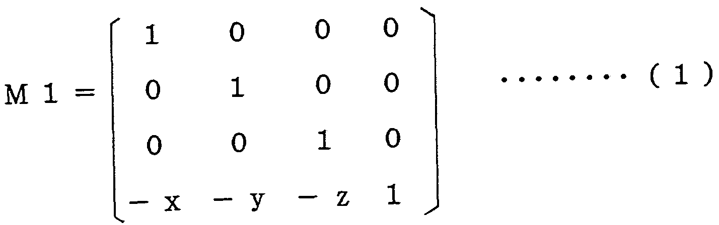
- step S104 a moving matrix M1 for moving the set passing point (X, y, z) to the origin of the absolute coordinate system, and the above set passing point ( X, y, z), the moving matrix M2, and the plane of the normal vector (0, 0, 1) (the XY plane of the absolute coordinate system) are converted to the normal vectors (i, j, k), the matrix M3 is calculated, and the motion curve defined on the H-V plane is converted to the normal vector (i, j, j) at the passing point (X, y, z).
- a plane orthogonal to an arbitrarily set plane is set as an operation section.
- an arbitrary plane 11 is set, and points on the reference curve BC, that is, passing points P1, P2, P3,. .. And the arbitrary points P 1 ′, P 2 ′, P 3 ′, ′ ”define the operation section DCS.
- the coordinate value of the passing point P 1 on the reference curve BC be (xl, y 1, zl)
- the coordinate position of the perpendicular P 1 ′ lowered from the passing point on the plane 11 be (x 2, Let y 2, ⁇ 2) and the coordinate position of the arbitrarily set point PI ”be (x 3, y 3, ⁇ 3).
- X 2 X 1+ a ⁇ d- (ax 1+ by 1+ cz 1) ⁇ / (a 2 + b 2 + c 2 )
- y 2 y 1.
- z 2 z 1+ c ⁇ d- (ax 1+ by 1+ cz 1) ⁇ / (a 2 + b 2 + c 2 )
- (xl , y 1, z 1) are the coordinate positions of the passing points
- a, b, c, d are known values determined by the setting of plane 11.
- a plane DCS passing through these three points is specified, and the normal vector of the plane DCS is defined by the perpendicular foot (x2, x2) from the passing point (xl, y1, z1). y2, z2) and the cross product of the vectors from the passing point (x1, y1, zl) to the arbitrarily set point (X3, y3, z3).
- Figure 8 is a processing flowchart of the method for setting the operation cross section DCS by this method.
- the processor 1 defines a plane at step S201, passes a point (X1, y1, z1) on the reference curve at step S202 and an arbitrary point (step S203) at step S203. x 3, y 3, z 3) are set.
- step S204 processor 1 is set from the set passing point.
- step S205 calculate the operation curve defined on the H-V plane from the above-mentioned normal vector and the set passing point is defined as the plane DCS of the normal vector obtained at the set passing point. That is, the vector M to be converted to the position in the absolute coordinate system is obtained in the same manner as described above.
- the operation cross section is set arbitrarily. As shown in FIG. 9, passing points P1, P2, P3,... On the reference curve BC are designated, and the operation cross section DCS at each point is specified. Specify the normal vectors nl, n2, n3,.... As a result, since one point on the plane DCS and the normal vector of the plane DCS are specified, the operation cross-section DCS is specified.
- the passing point on the reference curve BC is specified by step S301, and the operation cross section DCS at each point is specified by step S302.
- the matrix M for converting the operation curve into the position of the absolute coordinate system is obtained, and the operation cross-section coordinate system definition is completed.
- the normal vector n is If the tangent vector at the passing point of C is used, there is no need to set the normal vector. In this case, the tangent vector at the set passage point from the set reference curve BC may be automatically obtained by the function of the conventional CAD (function of the automatic programming device). It is only necessary to set the passing point of the reference curve BC.
- the operation section is set arbitrarily.
- any two points P1-, P1 ' By specifying P 2 *, P 2 ', ..., a plane passing through these three points is specified.
- the normal vector of this plane is determined by the cross product of the vectors from the passing point to any two points.
- FIG. 12 is a processing flowchart executed by the processor according to this method.
- a passing point on the reference curve BC is specified, and in step S402, any two points other than the passing point that defines the operation cross section are set and input.
- step S403 a vector from the passing point on the set reference curve BC to each of the set points is obtained, and an outer product of these two vectors is obtained.
- the normal vector of the operating cross section is obtained by using. From this normal vector and the set passing point position on the reference curve BC, a matrix M for converting the motion curve defined on the H-V plane into the position of the absolute coordinate system is obtained (step S404). ),
- the operation section coordinate system definition ends.
- an operation curve is defined on the H-V plane, and the operation shown in the above equation (6) is performed from the matrix M to perform the operation curve.
- an operation curve with the origin of the H-V plane as the set point of the reference curve is defined in the absolute coordinate system.
- a plane radially arranged about an arbitrary axis can be set as an operation section, and a plane orthogonal to an arbitrary plane is set as an operation section. It can be. Furthermore, any plane can be defined as a motion section.
- the operation curve it is possible to define the operation curve by adopting the optimal operation section specification method according to the characteristics of various free-form surfaces, and the degree of freedom in selecting the operation section that defines the operation curve is significantly improved. I do.
Landscapes
- Engineering & Computer Science (AREA)
- Physics & Mathematics (AREA)
- Theoretical Computer Science (AREA)
- General Physics & Mathematics (AREA)
- Computer Hardware Design (AREA)
- General Engineering & Computer Science (AREA)
- Computer Graphics (AREA)
- Geometry (AREA)
- Software Systems (AREA)
- Numerical Control (AREA)
Description


Claims
Priority Applications (1)
| Application Number | Priority Date | Filing Date | Title |
|---|---|---|---|
| KR1019930700788A KR930702118A (ko) | 1991-09-26 | 1992-09-25 | 자유곡면의 단면 좌표계의 정의 방법 |
Applications Claiming Priority (2)
| Application Number | Priority Date | Filing Date | Title |
|---|---|---|---|
| JP3/273499 | 1991-09-26 | ||
| JP3273499A JPH0589208A (ja) | 1991-09-26 | 1991-09-26 | 自由曲面定義における断面座標系定義方式 |
Publications (1)
| Publication Number | Publication Date |
|---|---|
| WO1993006558A1 true WO1993006558A1 (fr) | 1993-04-01 |
Family
ID=17528752
Family Applications (1)
| Application Number | Title | Priority Date | Filing Date |
|---|---|---|---|
| PCT/JP1992/001222 Ceased WO1993006558A1 (fr) | 1991-09-26 | 1992-09-25 | Procede pour definir le systeme de coordonnees d'une section d'un plan de courbe libre |
Country Status (4)
| Country | Link |
|---|---|
| EP (1) | EP0559906A1 (ja) |
| JP (1) | JPH0589208A (ja) |
| KR (1) | KR930702118A (ja) |
| WO (1) | WO1993006558A1 (ja) |
Cited By (1)
| Publication number | Priority date | Publication date | Assignee | Title |
|---|---|---|---|---|
| US6249705B1 (en) | 1999-10-21 | 2001-06-19 | Pacesetter, Inc. | Distributed network system for use with implantable medical devices |
Citations (2)
| Publication number | Priority date | Publication date | Assignee | Title |
|---|---|---|---|---|
| JPH01116884A (ja) * | 1987-10-30 | 1989-05-09 | Sony Corp | 物体の断面形状画像データ作成方法 |
| JPH01319868A (ja) * | 1988-06-21 | 1989-12-26 | Mitsubishi Electric Corp | 曲面生成方式 |
Family Cites Families (1)
| Publication number | Priority date | Publication date | Assignee | Title |
|---|---|---|---|---|
| AU626808B2 (en) * | 1987-10-26 | 1992-08-13 | Sony Corporation | Method and system for generating free curved surface |
-
1991
- 1991-09-26 JP JP3273499A patent/JPH0589208A/ja active Pending
-
1992
- 1992-09-25 WO PCT/JP1992/001222 patent/WO1993006558A1/ja not_active Ceased
- 1992-09-25 KR KR1019930700788A patent/KR930702118A/ko not_active Ceased
- 1992-09-25 EP EP92919862A patent/EP0559906A1/en not_active Withdrawn
Patent Citations (2)
| Publication number | Priority date | Publication date | Assignee | Title |
|---|---|---|---|---|
| JPH01116884A (ja) * | 1987-10-30 | 1989-05-09 | Sony Corp | 物体の断面形状画像データ作成方法 |
| JPH01319868A (ja) * | 1988-06-21 | 1989-12-26 | Mitsubishi Electric Corp | 曲面生成方式 |
Non-Patent Citations (1)
| Title |
|---|
| See also references of EP0559906A4 * |
Cited By (1)
| Publication number | Priority date | Publication date | Assignee | Title |
|---|---|---|---|---|
| US6249705B1 (en) | 1999-10-21 | 2001-06-19 | Pacesetter, Inc. | Distributed network system for use with implantable medical devices |
Also Published As
| Publication number | Publication date |
|---|---|
| KR930702118A (ko) | 1993-09-08 |
| EP0559906A4 (ja) | 1994-04-20 |
| EP0559906A1 (en) | 1993-09-15 |
| JPH0589208A (ja) | 1993-04-09 |
Similar Documents
| Publication | Publication Date | Title |
|---|---|---|
| WO1982003705A1 (fr) | Procede de formage de surface courbe | |
| CN111788036B (zh) | 用于生成工具路径的方法以及装置 | |
| TW200813677A (en) | Machine tool system control | |
| JPH08305430A (ja) | 自由曲線補間方式 | |
| JPH0373882B2 (ja) | ||
| WO1993006558A1 (fr) | Procede pour definir le systeme de coordonnees d'une section d'un plan de courbe libre | |
| KR900007163B1 (ko) | 복합곡면 생성방법 | |
| US5132913A (en) | Method and apparatus for creating a three-dimensional space curve by smoothly connecting a three-dimensional sequence of discretely given paints | |
| WO1988006312A1 (fr) | Procede de generation de surfaces courbes | |
| JPH0664486B2 (ja) | 3次元曲線作成方法 | |
| WO1993001535A1 (fr) | Procede servant a preciser l'emplacement d'une surface courbee de conge | |
| US20210365600A1 (en) | Structural analytical model apparatus and method | |
| JPWO2021162991A5 (ja) | ||
| WO1988000367A1 (en) | Method of forming cutting path of composite curved plane | |
| JPH06162147A (ja) | 構造物3次元曲面の計測解析装置 | |
| JP2972047B2 (ja) | スイープ立体生成装置 | |
| WO1987006032A1 (fr) | Procede permettant de preparer des donnees de commande numerique d'une surface courbe composite | |
| WO2019171599A1 (ja) | 工具経路生成方法 | |
| JP2767865B2 (ja) | ぼかし面データ自動作成装置 | |
| WO1993021569A1 (fr) | Procede de formation d'une coupe transversale lors de la creation d'une courbe gauche | |
| Ameddah et al. | NURBS interpolation strategies of complex surfaces in high speed machining | |
| JPH01116884A (ja) | 物体の断面形状画像データ作成方法 | |
| JP2822190B2 (ja) | 物体の表面形状データ作成方法 | |
| KR101997570B1 (ko) | 서브 g-코드 데이터를 이용하여 성형연삭기의 연삭 대상물에 대한 g-코드 프로그램을 고속 생성하는 g-코드 프로그램 생성 장치 및 그의 동작 방법 | |
| JPH02260081A (ja) | 自由曲線作成方法 |
Legal Events
| Date | Code | Title | Description |
|---|---|---|---|
| AK | Designated states |
Kind code of ref document: A1 Designated state(s): KR US |
|
| AL | Designated countries for regional patents |
Kind code of ref document: A1 Designated state(s): AT BE CH DE DK ES FR GB GR IE IT LU MC NL SE |
|
| ENP | Entry into the national phase |
Ref country code: US Ref document number: 1993 66042 Date of ref document: 19930520 Kind code of ref document: A Format of ref document f/p: F |
|
| WWE | Wipo information: entry into national phase |
Ref document number: 1992919862 Country of ref document: EP |
|
| WWP | Wipo information: published in national office |
Ref document number: 1992919862 Country of ref document: EP |
|
| WWW | Wipo information: withdrawn in national office |
Ref document number: 1992919862 Country of ref document: EP |