WO1996004122A1 - Skin material having plurality of minute recesses and projections in and on its surface, method of manufacturing the same, and method of manufacturing molded products using the same skin material - Google Patents
Skin material having plurality of minute recesses and projections in and on its surface, method of manufacturing the same, and method of manufacturing molded products using the same skin material Download PDFInfo
- Publication number
- WO1996004122A1 WO1996004122A1 PCT/JP1994/001256 JP9401256W WO9604122A1 WO 1996004122 A1 WO1996004122 A1 WO 1996004122A1 JP 9401256 W JP9401256 W JP 9401256W WO 9604122 A1 WO9604122 A1 WO 9604122A1
- Authority
- WO
- WIPO (PCT)
- Prior art keywords
- skin material
- sheet
- layer
- resin
- elastomer
- Prior art date
- Legal status (The legal status is an assumption and is not a legal conclusion. Google has not performed a legal analysis and makes no representation as to the accuracy of the status listed.)
- Ceased
Links
Classifications
-
- B—PERFORMING OPERATIONS; TRANSPORTING
- B32—LAYERED PRODUCTS
- B32B—LAYERED PRODUCTS, i.e. PRODUCTS BUILT-UP OF STRATA OF FLAT OR NON-FLAT, e.g. CELLULAR OR HONEYCOMB, FORM
- B32B27/00—Layered products comprising a layer of synthetic resin
- B32B27/18—Layered products comprising a layer of synthetic resin characterised by the use of special additives
- B32B27/20—Layered products comprising a layer of synthetic resin characterised by the use of special additives using fillers, pigments, thixotroping agents
-
- B—PERFORMING OPERATIONS; TRANSPORTING
- B08—CLEANING
- B08B—CLEANING IN GENERAL; PREVENTION OF FOULING IN GENERAL
- B08B17/00—Methods preventing fouling
- B08B17/02—Preventing deposition of fouling or of dust
- B08B17/06—Preventing deposition of fouling or of dust by giving articles subject to fouling a special shape or arrangement
- B08B17/065—Preventing deposition of fouling or of dust by giving articles subject to fouling a special shape or arrangement the surface having a microscopic surface pattern to achieve the same effect as a lotus flower
-
- B—PERFORMING OPERATIONS; TRANSPORTING
- B29—WORKING OF PLASTICS; WORKING OF SUBSTANCES IN A PLASTIC STATE IN GENERAL
- B29C—SHAPING OR JOINING OF PLASTICS; SHAPING OF MATERIAL IN A PLASTIC STATE, NOT OTHERWISE PROVIDED FOR; AFTER-TREATMENT OF THE SHAPED PRODUCTS, e.g. REPAIRING
- B29C45/00—Injection moulding, i.e. forcing the required volume of moulding material through a nozzle into a closed mould; Apparatus therefor
- B29C45/14—Injection moulding, i.e. forcing the required volume of moulding material through a nozzle into a closed mould; Apparatus therefor incorporating preformed parts or layers, e.g. injection moulding around inserts or for coating articles
- B29C45/14778—Injection moulding, i.e. forcing the required volume of moulding material through a nozzle into a closed mould; Apparatus therefor incorporating preformed parts or layers, e.g. injection moulding around inserts or for coating articles the article consisting of a material with particular properties, e.g. porous, brittle
- B29C45/14811—Multilayered articles
-
- B—PERFORMING OPERATIONS; TRANSPORTING
- B29—WORKING OF PLASTICS; WORKING OF SUBSTANCES IN A PLASTIC STATE IN GENERAL
- B29C—SHAPING OR JOINING OF PLASTICS; SHAPING OF MATERIAL IN A PLASTIC STATE, NOT OTHERWISE PROVIDED FOR; AFTER-TREATMENT OF THE SHAPED PRODUCTS, e.g. REPAIRING
- B29C48/00—Extrusion moulding, i.e. expressing the moulding material through a die or nozzle which imparts the desired form; Apparatus therefor
- B29C48/001—Combinations of extrusion moulding with other shaping operations
- B29C48/0013—Extrusion moulding in several steps, i.e. components merging outside the die
- B29C48/0014—Extrusion moulding in several steps, i.e. components merging outside the die producing flat articles having components brought in contact outside the extrusion die
-
- B—PERFORMING OPERATIONS; TRANSPORTING
- B29—WORKING OF PLASTICS; WORKING OF SUBSTANCES IN A PLASTIC STATE IN GENERAL
- B29C—SHAPING OR JOINING OF PLASTICS; SHAPING OF MATERIAL IN A PLASTIC STATE, NOT OTHERWISE PROVIDED FOR; AFTER-TREATMENT OF THE SHAPED PRODUCTS, e.g. REPAIRING
- B29C48/00—Extrusion moulding, i.e. expressing the moulding material through a die or nozzle which imparts the desired form; Apparatus therefor
- B29C48/03—Extrusion moulding, i.e. expressing the moulding material through a die or nozzle which imparts the desired form; Apparatus therefor characterised by the shape of the extruded material at extrusion
- B29C48/07—Flat, e.g. panels
- B29C48/08—Flat, e.g. panels flexible, e.g. films
-
- B—PERFORMING OPERATIONS; TRANSPORTING
- B29—WORKING OF PLASTICS; WORKING OF SUBSTANCES IN A PLASTIC STATE IN GENERAL
- B29C—SHAPING OR JOINING OF PLASTICS; SHAPING OF MATERIAL IN A PLASTIC STATE, NOT OTHERWISE PROVIDED FOR; AFTER-TREATMENT OF THE SHAPED PRODUCTS, e.g. REPAIRING
- B29C48/00—Extrusion moulding, i.e. expressing the moulding material through a die or nozzle which imparts the desired form; Apparatus therefor
- B29C48/16—Articles comprising two or more components, e.g. co-extruded layers
- B29C48/18—Articles comprising two or more components, e.g. co-extruded layers the components being layers
- B29C48/21—Articles comprising two or more components, e.g. co-extruded layers the components being layers the layers being joined at their surfaces
-
- B—PERFORMING OPERATIONS; TRANSPORTING
- B29—WORKING OF PLASTICS; WORKING OF SUBSTANCES IN A PLASTIC STATE IN GENERAL
- B29C—SHAPING OR JOINING OF PLASTICS; SHAPING OF MATERIAL IN A PLASTIC STATE, NOT OTHERWISE PROVIDED FOR; AFTER-TREATMENT OF THE SHAPED PRODUCTS, e.g. REPAIRING
- B29C51/00—Shaping by thermoforming, i.e. shaping sheets or sheet like preforms after heating, e.g. shaping sheets in matched moulds or by deep-drawing; Apparatus therefor
- B29C51/002—Shaping by thermoforming, i.e. shaping sheets or sheet like preforms after heating, e.g. shaping sheets in matched moulds or by deep-drawing; Apparatus therefor characterised by the choice of material
-
- B—PERFORMING OPERATIONS; TRANSPORTING
- B29—WORKING OF PLASTICS; WORKING OF SUBSTANCES IN A PLASTIC STATE IN GENERAL
- B29C—SHAPING OR JOINING OF PLASTICS; SHAPING OF MATERIAL IN A PLASTIC STATE, NOT OTHERWISE PROVIDED FOR; AFTER-TREATMENT OF THE SHAPED PRODUCTS, e.g. REPAIRING
- B29C55/00—Shaping by stretching, e.g. drawing through a die; Apparatus therefor
- B29C55/005—Shaping by stretching, e.g. drawing through a die; Apparatus therefor characterised by the choice of materials
-
- B—PERFORMING OPERATIONS; TRANSPORTING
- B29—WORKING OF PLASTICS; WORKING OF SUBSTANCES IN A PLASTIC STATE IN GENERAL
- B29C—SHAPING OR JOINING OF PLASTICS; SHAPING OF MATERIAL IN A PLASTIC STATE, NOT OTHERWISE PROVIDED FOR; AFTER-TREATMENT OF THE SHAPED PRODUCTS, e.g. REPAIRING
- B29C70/00—Shaping composites, i.e. plastics material comprising reinforcements, fillers or preformed parts, e.g. inserts
- B29C70/58—Shaping composites, i.e. plastics material comprising reinforcements, fillers or preformed parts, e.g. inserts comprising fillers only, e.g. particles, powder, beads, flakes, spheres
- B29C70/64—Shaping composites, i.e. plastics material comprising reinforcements, fillers or preformed parts, e.g. inserts comprising fillers only, e.g. particles, powder, beads, flakes, spheres the filler influencing the surface characteristics of the material, e.g. by concentrating near the surface or by incorporating in the surface by force
-
- B—PERFORMING OPERATIONS; TRANSPORTING
- B29—WORKING OF PLASTICS; WORKING OF SUBSTANCES IN A PLASTIC STATE IN GENERAL
- B29C—SHAPING OR JOINING OF PLASTICS; SHAPING OF MATERIAL IN A PLASTIC STATE, NOT OTHERWISE PROVIDED FOR; AFTER-TREATMENT OF THE SHAPED PRODUCTS, e.g. REPAIRING
- B29C70/00—Shaping composites, i.e. plastics material comprising reinforcements, fillers or preformed parts, e.g. inserts
- B29C70/68—Shaping composites, i.e. plastics material comprising reinforcements, fillers or preformed parts, e.g. inserts by incorporating or moulding on preformed parts, e.g. inserts or layers, e.g. foam blocks
- B29C70/78—Moulding material on one side only of the preformed part
-
- B—PERFORMING OPERATIONS; TRANSPORTING
- B29—WORKING OF PLASTICS; WORKING OF SUBSTANCES IN A PLASTIC STATE IN GENERAL
- B29D—PRODUCING PARTICULAR ARTICLES FROM PLASTICS OR FROM SUBSTANCES IN A PLASTIC STATE
- B29D7/00—Producing flat articles, e.g. films or sheets
- B29D7/01—Films or sheets
-
- B—PERFORMING OPERATIONS; TRANSPORTING
- B32—LAYERED PRODUCTS
- B32B—LAYERED PRODUCTS, i.e. PRODUCTS BUILT-UP OF STRATA OF FLAT OR NON-FLAT, e.g. CELLULAR OR HONEYCOMB, FORM
- B32B27/00—Layered products comprising a layer of synthetic resin
- B32B27/06—Layered products comprising a layer of synthetic resin as the main or only constituent of a layer, which is next to another layer of the same or of a different material
- B32B27/065—Layered products comprising a layer of synthetic resin as the main or only constituent of a layer, which is next to another layer of the same or of a different material of foam
-
- B—PERFORMING OPERATIONS; TRANSPORTING
- B32—LAYERED PRODUCTS
- B32B—LAYERED PRODUCTS, i.e. PRODUCTS BUILT-UP OF STRATA OF FLAT OR NON-FLAT, e.g. CELLULAR OR HONEYCOMB, FORM
- B32B27/00—Layered products comprising a layer of synthetic resin
- B32B27/06—Layered products comprising a layer of synthetic resin as the main or only constituent of a layer, which is next to another layer of the same or of a different material
- B32B27/08—Layered products comprising a layer of synthetic resin as the main or only constituent of a layer, which is next to another layer of the same or of a different material of synthetic resin
-
- B—PERFORMING OPERATIONS; TRANSPORTING
- B32—LAYERED PRODUCTS
- B32B—LAYERED PRODUCTS, i.e. PRODUCTS BUILT-UP OF STRATA OF FLAT OR NON-FLAT, e.g. CELLULAR OR HONEYCOMB, FORM
- B32B27/00—Layered products comprising a layer of synthetic resin
- B32B27/32—Layered products comprising a layer of synthetic resin comprising polyolefins
-
- B—PERFORMING OPERATIONS; TRANSPORTING
- B32—LAYERED PRODUCTS
- B32B—LAYERED PRODUCTS, i.e. PRODUCTS BUILT-UP OF STRATA OF FLAT OR NON-FLAT, e.g. CELLULAR OR HONEYCOMB, FORM
- B32B27/00—Layered products comprising a layer of synthetic resin
- B32B27/40—Layered products comprising a layer of synthetic resin comprising polyurethanes
-
- B—PERFORMING OPERATIONS; TRANSPORTING
- B32—LAYERED PRODUCTS
- B32B—LAYERED PRODUCTS, i.e. PRODUCTS BUILT-UP OF STRATA OF FLAT OR NON-FLAT, e.g. CELLULAR OR HONEYCOMB, FORM
- B32B38/00—Ancillary operations in connection with laminating processes
-
- B—PERFORMING OPERATIONS; TRANSPORTING
- B32—LAYERED PRODUCTS
- B32B—LAYERED PRODUCTS, i.e. PRODUCTS BUILT-UP OF STRATA OF FLAT OR NON-FLAT, e.g. CELLULAR OR HONEYCOMB, FORM
- B32B5/00—Layered products characterised by the non- homogeneity or physical structure, i.e. comprising a fibrous, filamentary, particulate or foam layer; Layered products characterised by having a layer differing constitutionally or physically in different parts
- B32B5/18—Layered products characterised by the non- homogeneity or physical structure, i.e. comprising a fibrous, filamentary, particulate or foam layer; Layered products characterised by having a layer differing constitutionally or physically in different parts characterised by features of a layer of foamed material
-
- B—PERFORMING OPERATIONS; TRANSPORTING
- B32—LAYERED PRODUCTS
- B32B—LAYERED PRODUCTS, i.e. PRODUCTS BUILT-UP OF STRATA OF FLAT OR NON-FLAT, e.g. CELLULAR OR HONEYCOMB, FORM
- B32B7/00—Layered products characterised by the relation between layers; Layered products characterised by the relative orientation of features between layers, or by the relative values of a measurable parameter between layers, i.e. products comprising layers having different physical, chemical or physicochemical properties; Layered products characterised by the interconnection of layers
- B32B7/04—Interconnection of layers
- B32B7/12—Interconnection of layers using interposed adhesives or interposed materials with bonding properties
-
- B—PERFORMING OPERATIONS; TRANSPORTING
- B29—WORKING OF PLASTICS; WORKING OF SUBSTANCES IN A PLASTIC STATE IN GENERAL
- B29C—SHAPING OR JOINING OF PLASTICS; SHAPING OF MATERIAL IN A PLASTIC STATE, NOT OTHERWISE PROVIDED FOR; AFTER-TREATMENT OF THE SHAPED PRODUCTS, e.g. REPAIRING
- B29C45/00—Injection moulding, i.e. forcing the required volume of moulding material through a nozzle into a closed mould; Apparatus therefor
- B29C45/14—Injection moulding, i.e. forcing the required volume of moulding material through a nozzle into a closed mould; Apparatus therefor incorporating preformed parts or layers, e.g. injection moulding around inserts or for coating articles
- B29C45/1418—Injection moulding, i.e. forcing the required volume of moulding material through a nozzle into a closed mould; Apparatus therefor incorporating preformed parts or layers, e.g. injection moulding around inserts or for coating articles the inserts being deformed or preformed, e.g. by the injection pressure
- B29C2045/14237—Injection moulding, i.e. forcing the required volume of moulding material through a nozzle into a closed mould; Apparatus therefor incorporating preformed parts or layers, e.g. injection moulding around inserts or for coating articles the inserts being deformed or preformed, e.g. by the injection pressure the inserts being deformed or preformed outside the mould or mould cavity
-
- B—PERFORMING OPERATIONS; TRANSPORTING
- B29—WORKING OF PLASTICS; WORKING OF SUBSTANCES IN A PLASTIC STATE IN GENERAL
- B29C—SHAPING OR JOINING OF PLASTICS; SHAPING OF MATERIAL IN A PLASTIC STATE, NOT OTHERWISE PROVIDED FOR; AFTER-TREATMENT OF THE SHAPED PRODUCTS, e.g. REPAIRING
- B29C2791/00—Shaping characteristics in general
- B29C2791/004—Shaping under special conditions
- B29C2791/006—Using vacuum
-
- B—PERFORMING OPERATIONS; TRANSPORTING
- B29—WORKING OF PLASTICS; WORKING OF SUBSTANCES IN A PLASTIC STATE IN GENERAL
- B29C—SHAPING OR JOINING OF PLASTICS; SHAPING OF MATERIAL IN A PLASTIC STATE, NOT OTHERWISE PROVIDED FOR; AFTER-TREATMENT OF THE SHAPED PRODUCTS, e.g. REPAIRING
- B29C43/00—Compression moulding, i.e. applying external pressure to flow the moulding material; Apparatus therefor
- B29C43/02—Compression moulding, i.e. applying external pressure to flow the moulding material; Apparatus therefor of articles of definite length, i.e. discrete articles
- B29C43/18—Compression moulding, i.e. applying external pressure to flow the moulding material; Apparatus therefor of articles of definite length, i.e. discrete articles incorporating preformed parts or layers, e.g. compression moulding around inserts or for coating articles
- B29C43/183—Compression moulding, i.e. applying external pressure to flow the moulding material; Apparatus therefor of articles of definite length, i.e. discrete articles incorporating preformed parts or layers, e.g. compression moulding around inserts or for coating articles the preformed layer being a lining, e.g. shaped in the mould before compression moulding, or a preformed shell adapted to the shape of the mould
-
- B—PERFORMING OPERATIONS; TRANSPORTING
- B29—WORKING OF PLASTICS; WORKING OF SUBSTANCES IN A PLASTIC STATE IN GENERAL
- B29C—SHAPING OR JOINING OF PLASTICS; SHAPING OF MATERIAL IN A PLASTIC STATE, NOT OTHERWISE PROVIDED FOR; AFTER-TREATMENT OF THE SHAPED PRODUCTS, e.g. REPAIRING
- B29C48/00—Extrusion moulding, i.e. expressing the moulding material through a die or nozzle which imparts the desired form; Apparatus therefor
- B29C48/001—Combinations of extrusion moulding with other shaping operations
- B29C48/0011—Combinations of extrusion moulding with other shaping operations combined with compression moulding
-
- B—PERFORMING OPERATIONS; TRANSPORTING
- B29—WORKING OF PLASTICS; WORKING OF SUBSTANCES IN A PLASTIC STATE IN GENERAL
- B29C—SHAPING OR JOINING OF PLASTICS; SHAPING OF MATERIAL IN A PLASTIC STATE, NOT OTHERWISE PROVIDED FOR; AFTER-TREATMENT OF THE SHAPED PRODUCTS, e.g. REPAIRING
- B29C48/00—Extrusion moulding, i.e. expressing the moulding material through a die or nozzle which imparts the desired form; Apparatus therefor
- B29C48/001—Combinations of extrusion moulding with other shaping operations
- B29C48/0017—Combinations of extrusion moulding with other shaping operations combined with blow-moulding or thermoforming
-
- B—PERFORMING OPERATIONS; TRANSPORTING
- B29—WORKING OF PLASTICS; WORKING OF SUBSTANCES IN A PLASTIC STATE IN GENERAL
- B29C—SHAPING OR JOINING OF PLASTICS; SHAPING OF MATERIAL IN A PLASTIC STATE, NOT OTHERWISE PROVIDED FOR; AFTER-TREATMENT OF THE SHAPED PRODUCTS, e.g. REPAIRING
- B29C51/00—Shaping by thermoforming, i.e. shaping sheets or sheet like preforms after heating, e.g. shaping sheets in matched moulds or by deep-drawing; Apparatus therefor
- B29C51/10—Forming by pressure difference, e.g. vacuum
-
- B—PERFORMING OPERATIONS; TRANSPORTING
- B29—WORKING OF PLASTICS; WORKING OF SUBSTANCES IN A PLASTIC STATE IN GENERAL
- B29C—SHAPING OR JOINING OF PLASTICS; SHAPING OF MATERIAL IN A PLASTIC STATE, NOT OTHERWISE PROVIDED FOR; AFTER-TREATMENT OF THE SHAPED PRODUCTS, e.g. REPAIRING
- B29C51/00—Shaping by thermoforming, i.e. shaping sheets or sheet like preforms after heating, e.g. shaping sheets in matched moulds or by deep-drawing; Apparatus therefor
- B29C51/14—Shaping by thermoforming, i.e. shaping sheets or sheet like preforms after heating, e.g. shaping sheets in matched moulds or by deep-drawing; Apparatus therefor using multilayered preforms or sheets
-
- B—PERFORMING OPERATIONS; TRANSPORTING
- B29—WORKING OF PLASTICS; WORKING OF SUBSTANCES IN A PLASTIC STATE IN GENERAL
- B29K—INDEXING SCHEME ASSOCIATED WITH SUBCLASSES B29B, B29C OR B29D, RELATING TO MOULDING MATERIALS OR TO MATERIALS FOR MOULDS, REINFORCEMENTS, FILLERS OR PREFORMED PARTS, e.g. INSERTS
- B29K2021/00—Use of unspecified rubbers as moulding material
-
- B—PERFORMING OPERATIONS; TRANSPORTING
- B29—WORKING OF PLASTICS; WORKING OF SUBSTANCES IN A PLASTIC STATE IN GENERAL
- B29K—INDEXING SCHEME ASSOCIATED WITH SUBCLASSES B29B, B29C OR B29D, RELATING TO MOULDING MATERIALS OR TO MATERIALS FOR MOULDS, REINFORCEMENTS, FILLERS OR PREFORMED PARTS, e.g. INSERTS
- B29K2023/00—Use of polyalkenes or derivatives thereof as moulding material
- B29K2023/04—Polymers of ethylene
- B29K2023/08—Copolymers of ethylene
- B29K2023/083—EVA, i.e. ethylene vinyl acetate copolymer
-
- B—PERFORMING OPERATIONS; TRANSPORTING
- B29—WORKING OF PLASTICS; WORKING OF SUBSTANCES IN A PLASTIC STATE IN GENERAL
- B29K—INDEXING SCHEME ASSOCIATED WITH SUBCLASSES B29B, B29C OR B29D, RELATING TO MOULDING MATERIALS OR TO MATERIALS FOR MOULDS, REINFORCEMENTS, FILLERS OR PREFORMED PARTS, e.g. INSERTS
- B29K2023/00—Use of polyalkenes or derivatives thereof as moulding material
- B29K2023/18—Polymers of hydrocarbons having four or more carbon atoms, e.g. polymers of butylene, e.g. PB, i.e. polybutylene
- B29K2023/22—Copolymers of isobutene, e.g. butyl rubber
-
- B—PERFORMING OPERATIONS; TRANSPORTING
- B29—WORKING OF PLASTICS; WORKING OF SUBSTANCES IN A PLASTIC STATE IN GENERAL
- B29K—INDEXING SCHEME ASSOCIATED WITH SUBCLASSES B29B, B29C OR B29D, RELATING TO MOULDING MATERIALS OR TO MATERIALS FOR MOULDS, REINFORCEMENTS, FILLERS OR PREFORMED PARTS, e.g. INSERTS
- B29K2075/00—Use of PU, i.e. polyureas or polyurethanes or derivatives thereof, as moulding material
-
- B—PERFORMING OPERATIONS; TRANSPORTING
- B29—WORKING OF PLASTICS; WORKING OF SUBSTANCES IN A PLASTIC STATE IN GENERAL
- B29K—INDEXING SCHEME ASSOCIATED WITH SUBCLASSES B29B, B29C OR B29D, RELATING TO MOULDING MATERIALS OR TO MATERIALS FOR MOULDS, REINFORCEMENTS, FILLERS OR PREFORMED PARTS, e.g. INSERTS
- B29K2101/00—Use of unspecified macromolecular compounds as moulding material
- B29K2101/12—Thermoplastic materials
-
- B—PERFORMING OPERATIONS; TRANSPORTING
- B29—WORKING OF PLASTICS; WORKING OF SUBSTANCES IN A PLASTIC STATE IN GENERAL
- B29K—INDEXING SCHEME ASSOCIATED WITH SUBCLASSES B29B, B29C OR B29D, RELATING TO MOULDING MATERIALS OR TO MATERIALS FOR MOULDS, REINFORCEMENTS, FILLERS OR PREFORMED PARTS, e.g. INSERTS
- B29K2105/00—Condition, form or state of moulded material or of the material to be shaped
- B29K2105/06—Condition, form or state of moulded material or of the material to be shaped containing reinforcements, fillers or inserts
- B29K2105/16—Fillers
-
- B—PERFORMING OPERATIONS; TRANSPORTING
- B29—WORKING OF PLASTICS; WORKING OF SUBSTANCES IN A PLASTIC STATE IN GENERAL
- B29K—INDEXING SCHEME ASSOCIATED WITH SUBCLASSES B29B, B29C OR B29D, RELATING TO MOULDING MATERIALS OR TO MATERIALS FOR MOULDS, REINFORCEMENTS, FILLERS OR PREFORMED PARTS, e.g. INSERTS
- B29K2105/00—Condition, form or state of moulded material or of the material to be shaped
- B29K2105/25—Solid
- B29K2105/251—Particles, powder or granules
-
- B—PERFORMING OPERATIONS; TRANSPORTING
- B29—WORKING OF PLASTICS; WORKING OF SUBSTANCES IN A PLASTIC STATE IN GENERAL
- B29K—INDEXING SCHEME ASSOCIATED WITH SUBCLASSES B29B, B29C OR B29D, RELATING TO MOULDING MATERIALS OR TO MATERIALS FOR MOULDS, REINFORCEMENTS, FILLERS OR PREFORMED PARTS, e.g. INSERTS
- B29K2715/00—Condition, form or state of preformed parts, e.g. inserts
- B29K2715/003—Cellular or porous
-
- B—PERFORMING OPERATIONS; TRANSPORTING
- B29—WORKING OF PLASTICS; WORKING OF SUBSTANCES IN A PLASTIC STATE IN GENERAL
- B29K—INDEXING SCHEME ASSOCIATED WITH SUBCLASSES B29B, B29C OR B29D, RELATING TO MOULDING MATERIALS OR TO MATERIALS FOR MOULDS, REINFORCEMENTS, FILLERS OR PREFORMED PARTS, e.g. INSERTS
- B29K2715/00—Condition, form or state of preformed parts, e.g. inserts
- B29K2715/006—Glues or adhesives, e.g. hot melts or thermofusible adhesives
-
- B—PERFORMING OPERATIONS; TRANSPORTING
- B29—WORKING OF PLASTICS; WORKING OF SUBSTANCES IN A PLASTIC STATE IN GENERAL
- B29K—INDEXING SCHEME ASSOCIATED WITH SUBCLASSES B29B, B29C OR B29D, RELATING TO MOULDING MATERIALS OR TO MATERIALS FOR MOULDS, REINFORCEMENTS, FILLERS OR PREFORMED PARTS, e.g. INSERTS
- B29K2995/00—Properties of moulding materials, reinforcements, fillers, preformed parts or moulds
- B29K2995/0037—Other properties
- B29K2995/0072—Roughness, e.g. anti-slip
-
- B—PERFORMING OPERATIONS; TRANSPORTING
- B32—LAYERED PRODUCTS
- B32B—LAYERED PRODUCTS, i.e. PRODUCTS BUILT-UP OF STRATA OF FLAT OR NON-FLAT, e.g. CELLULAR OR HONEYCOMB, FORM
- B32B2305/00—Condition, form or state of the layers or laminate
- B32B2305/30—Fillers, e.g. particles, powders, beads, flakes, spheres, chips
-
- B—PERFORMING OPERATIONS; TRANSPORTING
- B32—LAYERED PRODUCTS
- B32B—LAYERED PRODUCTS, i.e. PRODUCTS BUILT-UP OF STRATA OF FLAT OR NON-FLAT, e.g. CELLULAR OR HONEYCOMB, FORM
- B32B37/00—Methods or apparatus for laminating, e.g. by curing or by ultrasonic bonding
- B32B37/14—Methods or apparatus for laminating, e.g. by curing or by ultrasonic bonding characterised by the properties of the layers
- B32B37/15—Methods or apparatus for laminating, e.g. by curing or by ultrasonic bonding characterised by the properties of the layers with at least one layer being manufactured and immediately laminated before reaching its stable state, e.g. in which a layer is extruded and laminated while in semi-molten state
- B32B37/153—Methods or apparatus for laminating, e.g. by curing or by ultrasonic bonding characterised by the properties of the layers with at least one layer being manufactured and immediately laminated before reaching its stable state, e.g. in which a layer is extruded and laminated while in semi-molten state at least one layer is extruded and immediately laminated while in semi-molten state
-
- Y—GENERAL TAGGING OF NEW TECHNOLOGICAL DEVELOPMENTS; GENERAL TAGGING OF CROSS-SECTIONAL TECHNOLOGIES SPANNING OVER SEVERAL SECTIONS OF THE IPC; TECHNICAL SUBJECTS COVERED BY FORMER USPC CROSS-REFERENCE ART COLLECTIONS [XRACs] AND DIGESTS
- Y10—TECHNICAL SUBJECTS COVERED BY FORMER USPC
- Y10T—TECHNICAL SUBJECTS COVERED BY FORMER US CLASSIFICATION
- Y10T428/00—Stock material or miscellaneous articles
- Y10T428/24—Structurally defined web or sheet [e.g., overall dimension, etc.]
- Y10T428/24479—Structurally defined web or sheet [e.g., overall dimension, etc.] including variation in thickness
- Y10T428/24496—Foamed or cellular component
- Y10T428/24504—Component comprises a polymer [e.g., rubber, etc.]
- Y10T428/24512—Polyurethane
-
- Y—GENERAL TAGGING OF NEW TECHNOLOGICAL DEVELOPMENTS; GENERAL TAGGING OF CROSS-SECTIONAL TECHNOLOGIES SPANNING OVER SEVERAL SECTIONS OF THE IPC; TECHNICAL SUBJECTS COVERED BY FORMER USPC CROSS-REFERENCE ART COLLECTIONS [XRACs] AND DIGESTS
- Y10—TECHNICAL SUBJECTS COVERED BY FORMER USPC
- Y10T—TECHNICAL SUBJECTS COVERED BY FORMER US CLASSIFICATION
- Y10T428/00—Stock material or miscellaneous articles
- Y10T428/24—Structurally defined web or sheet [e.g., overall dimension, etc.]
- Y10T428/24479—Structurally defined web or sheet [e.g., overall dimension, etc.] including variation in thickness
- Y10T428/24612—Composite web or sheet
-
- Y—GENERAL TAGGING OF NEW TECHNOLOGICAL DEVELOPMENTS; GENERAL TAGGING OF CROSS-SECTIONAL TECHNOLOGIES SPANNING OVER SEVERAL SECTIONS OF THE IPC; TECHNICAL SUBJECTS COVERED BY FORMER USPC CROSS-REFERENCE ART COLLECTIONS [XRACs] AND DIGESTS
- Y10—TECHNICAL SUBJECTS COVERED BY FORMER USPC
- Y10T—TECHNICAL SUBJECTS COVERED BY FORMER US CLASSIFICATION
- Y10T428/00—Stock material or miscellaneous articles
- Y10T428/249921—Web or sheet containing structurally defined element or component
- Y10T428/249953—Composite having voids in a component [e.g., porous, cellular, etc.]
- Y10T428/249978—Voids specified as micro
- Y10T428/24998—Composite has more than two layers
-
- Y—GENERAL TAGGING OF NEW TECHNOLOGICAL DEVELOPMENTS; GENERAL TAGGING OF CROSS-SECTIONAL TECHNOLOGIES SPANNING OVER SEVERAL SECTIONS OF THE IPC; TECHNICAL SUBJECTS COVERED BY FORMER USPC CROSS-REFERENCE ART COLLECTIONS [XRACs] AND DIGESTS
- Y10—TECHNICAL SUBJECTS COVERED BY FORMER USPC
- Y10T—TECHNICAL SUBJECTS COVERED BY FORMER US CLASSIFICATION
- Y10T428/00—Stock material or miscellaneous articles
- Y10T428/249921—Web or sheet containing structurally defined element or component
- Y10T428/249953—Composite having voids in a component [e.g., porous, cellular, etc.]
- Y10T428/249982—With component specified as adhesive or bonding agent
-
- Y—GENERAL TAGGING OF NEW TECHNOLOGICAL DEVELOPMENTS; GENERAL TAGGING OF CROSS-SECTIONAL TECHNOLOGIES SPANNING OVER SEVERAL SECTIONS OF THE IPC; TECHNICAL SUBJECTS COVERED BY FORMER USPC CROSS-REFERENCE ART COLLECTIONS [XRACs] AND DIGESTS
- Y10—TECHNICAL SUBJECTS COVERED BY FORMER USPC
- Y10T—TECHNICAL SUBJECTS COVERED BY FORMER US CLASSIFICATION
- Y10T428/00—Stock material or miscellaneous articles
- Y10T428/249921—Web or sheet containing structurally defined element or component
- Y10T428/249953—Composite having voids in a component [e.g., porous, cellular, etc.]
- Y10T428/249986—Void-containing component contains also a solid fiber or solid particle
Definitions
- the present invention automotive interior materials Ya, and architectural ⁇ material, off office • Auto menu over three down equipment, c c-di-down Guya, such as home appliances, sentence equipment, sanitization rie, daily necessities
- c c-di-down Guya such as home appliances, sentence equipment, sanitization rie
- the present invention relates to a skin material capable of giving a tactile sensation, that is, a soft touch feeling, a method of manufacturing the skin material, and a method of manufacturing a molded article using the skin material.
- Fascinating sensation on surfaces such as plastic moldings or gold moldings (for example, paints or molding sheets obtained using paints to give a soothing, soothing outer surface) More suede-type films have been formed.
- Japanese Unexamined Patent Publication (Kokai) No. 2-12443 discloses that a bead pigment is separated on a base film having good moldability and that a radiation curable resin is added to a vehicle.
- a sheet for suede-like molding formed by applying and curing a paint has been proposed.
- this suede-like sheet it is necessary to apply an ionizing radiation-curable resin composition onto a film and then irradiate it with an electron beam or the like to cure the sheet. The process becomes complicated and productivity is not sufficient.
- the coating film of the sheet is made of a resin framed by an electron beam or the like, the spreadability of the entire sheet is inferior.
- the sheet may be broken due to poor spreadability of the sheet.
- Japanese Patent Application Laid-Open No. 62-251111 discloses a method in which a thermosetting resin sheet is set in a lower mold in advance, and then the resin is introduced into the lower mold. There has been proposed a method of manufacturing a molded product in which a thermoplastic resin sheet (decorative sheet) is adhered to the surface by pressing an upper die.
- the molded article obtained by the method disclosed in Japanese Patent Application Laid-Open No. 62-251111 has a surface ⁇ formed of only a thermoplastic resin.
- the feeling of removing the bran is not exhibited, and the feel when touched is hard. Therefore, this manufacturing method could not produce a product that requires 86 erasure and soft touch, for example, a car interior material, a housing, and a case. M indication of invention
- the present invention has been made to solve the above-mentioned problems, and a skin material whose appearance has a matte appearance and which usually has a soft touch when touched is provided. To provide a method for producing it with high productivity without causing problems of the conventional painting space and environmental problems such as solvents, and a method for producing a molded product using the skin material. This is the purpose.
- Another object of the present invention is to provide a method capable of producing the above K skin material at a relatively low cost.
- the skin material of the present invention is composed of a composition containing a urethane-based thermoplastic elastomer and elastic fine particles as main components, and has a surface having many fine irregularities on the surface.
- a layer, an adhesive layer, and a base material layer made of a thermoplastic resin-based elastomer are laminated in this order ⁇ .
- a composition containing a thermoplastic elastomer and a conductive fine particle as a main component is extruded and then stretched, so that a surface is obtained by extruding the composition. It is intended to obtain a skin material having many fine irregularities.
- the skin material obtained by the method of the present invention is formed of a composition mainly composed of a thermoplastic elastomer and elastic fine particles, and has a surface provided with a large number of fine irregularities on the surface. Since it has the layer, it is possible to give the surface of the molded article or the like a glossy appearance and a soft touch when touched.
- a composition mainly composed of a thermoplastic elastomer and elastic fine particles is extruded in a sheet form from an extruder, and then extruded.
- a large number of fine irregularities are formed on the surface, so that a good working environment can be produced without using a solvent.
- the co-extrusion method is used, so that continuous production can be performed in a single process compared to the case where the coating material is applied after the base material layer is formed.
- the skin material which has a matte appearance and usually has a soft touch when touched, can cause problems with the conventional painting space and environmental problems such as solvents. It can be easily manufactured with extremely high productivity.
- thermoplastic elastomer (Thermoplastic elastomer)
- thermoplastic elastomer used in the present invention refers to a polymer material that exhibits a certain rubber elasticity at normal temperature and is plasticized at high temperature and can be subjected to various molding processes.
- thermoplastic elastomer examples include polyurethan, polystyrene, polyolefin, polyester, and polychlorinated. Vinyl type, Polyamide type, Ionomer type, Fluoro rubber type, 1,2 Polybutadiene type, Trans 1, 4 Polyisolate Examples include a plant system and a synthetic natural rubber system, which may be used alone or in combination.
- thermoplastic elastomers are composed of a rubber component (hard segment) having an o-bee elasticity in the molecule and a molecular constraint component (soft core) for preventing bi-directional deformation.
- hard segment rubber component having an o-bee elasticity in the molecule
- soft core molecular constraint component
- Gume emissions g) often and this that share a, although in the moldable range also ⁇ to have a part Katachibana structure, three-dimensional network crosslinked structure of a wide range does not possess ⁇
- the hardness of these heat-soluble SB elastomers varies depending on the desired feel and the hardness of the elastic micro-lacquer used (a large number of bead beads are used). It is preferable that the hardness of JISK6301 is 20 to 98.
- a polyurethan or a soft segment is used as a hard segment.
- block copolymers having a polyether, a polyester, a polycarbonate, and the like are block copolymers having a polyether, a polyester, a polycarbonate, and the like.
- polystyrene polystyrene is used as the hard segment, and polybutadiene and poly is used as the soft segment.
- Block copolymers with Soprene, Polyethylene and Polybutylene in this order, SBS, SIS, SEBS block copolymers
- hydrogenation And those with a functional group.
- the hard segment has a polyrefined polyline as a hard segment
- the soft segment Those with ethylene and those with a small amount of diene components along with ethylene (in order, EPM (ethylene-propylene-methylene), EPDM ( Ethylene-propylene-gen-methylene copolymer), collectively EPR (ethylene-propylene rubber)), obtained by blending these These are partially crosslinked by further adding an organic peroxide, or are modified with an unsaturated hydrocyanic acid monomer or an unsaturated carboxylic acid derivative by graphitization.
- the hard segment and soft segment blends can be created and then blended, or can be blended when mounted. is there.
- polyester type there are a polyester as a dosegment and a copolymer having a polyether as a soft segment.
- polyamide there are some that use polyamide as hard segment and use polyether as soft segment. .
- thermoplastic elastomers depend on the tt ability desired to be obtained as a skin material, for example, scratch resistance, abrasion resistance.
- a urethane-based heat-resistant ffl elastomer is preferably used. If urethane-based elastomers require light resistance and heat resistance of the skin material, use a non-yellowing type that uses aliphatic isocyanate. Is preferably used 0
- the elastic fine particles those that do not dissolve under the extrusion conditions of the thermoplastic elastomer are used. That is, elastic fine particles having a higher temperature than the extrusion temperature of the thermoplastic elastomer are used. The reason is that when mixed with a heat-resistant elastomer and extruded in a sheet form from an extruder, the fine particles are melted and integrated into a heat-resistant elastomer. This is because even if the sheet is stretched thereafter, it is difficult to form irregularities of a desired size and shape on the surface of the sheet.
- the hydrophilic fine particles used in the present invention are fine particles having a property K of recovering the elasticity when opened after being pressurized until its shape is deformed.
- the load is 0.5 to 3
- O g i is preferable, and particularly, 0.5 to 10 g i is preferable.
- non-natural elastic fine particles are used as the volatile fine particles.
- polyurethane, acryl resin (preferably acryl-urethane resin), polystyrene, and styrene-isoprene examples thereof include those made of a polymer.
- the shape of these elastic fine particles is not limited to a preferably spherical force-spherical shape, but a non-spherical shape obtained by means such as freeze-pulverization can also be used.
- the average particle size of the elastic fine particles is usually in the range of 1 to 50; ⁇ , preferably in the range of 5 to 40 #m, and is preferably in the range of 100 to 100 parts by weight of the above-mentioned thermoplastic SE elastomer. Usually, 20 to 200 parts by weight, preferably 50 to 150 parts by weight, is added.
- the average particle size of the elastic fine particles is less than 1 zm, it is difficult to obtain a skin material having a sufficient soft touch feeling (a soft soft touch when touched). If it is extremely small, a feeling of erasure cannot be exhibited.
- the average particle size of the elastic fine particles exceeds 50 m, S cracks are likely to occur on the surface when the skin material is stretched and stretched.
- the amount added to 100 parts by weight of the heat-resistant elastomer is less than 20 parts by weight, many fine irregularities are not formed on the surface of the skin material. As a result, the feeling of mattness and soft touch of the skin material is reduced, and if the addition amount is more than 200 parts by weight, cracks are formed on the surface of the spread and stretched skin material. It is likely to occur.
- the number of the elastic fine particles is not limited to one type, and two or more types may be used in combination. If a relatively soft thermoplastic elastomer is used, or if the surface of the skin material has a slightly hard feel, use, for example, Methyl Tachibana Polymethyl acrylate. Alternatively, hard fine particles made of an inorganic material may be used together with the elastic fine particles.
- the surface JB is made of a composition containing a urethane-based thermoplastic elastomer and elastic fine particles as main components, and has many fine irregularities on the surface. is there.
- the base material layer is made of a 23-year-old refrigerated thermoplastic elastomer.
- the adhesive layer of both is not particularly limited, but is preferably a polyolefin modified with an acid such as an unsaturated polybasic acid (particularly polypropylene). And a layer composed of SEBS (styrene-ethylene-butylene-styrene copolymer) modified with an acid such as an unsaturated polybasic acid.
- the base material layer is laminated on the surface layer via the adhesive layer, the elastic fine particles are contained only in the surface layer of the skin material, compared to the case where the elastic particles are contained in the whole laminate. Thus, the amount of elastic micro-child used can be reduced.
- the base material ⁇ of the same type as the molding resin, for example, the molten resin and the skin material are integrated in the mold during the production of an injection molded product or a standing molded product. When they are formed, the adhesion between them becomes good.
- adhesive IS and substrate layer The same applies to the resin foam layer, which includes polyolefin resin, polystyrene resin, polyurethan resin, polyvinyl chloride resin, Foaming layers of various types of thermoplastic elastomer resins, etc., are particularly good in adhesiveness to the olefin-based thermoplastic elastomer base material layer, and the cushioning A foamed layer of a boro-refin-based resin is preferably used because of its excellent properties and, in addition, the soft touch feeling of the surface layer when pressed.
- composition containing the laster, elastic fine particles and, if necessary, additives is melted and mixed using a kneading and extruding device such as a 2-glaze extruder, and the sheet is pressed down. Then, the sheet material is stretched in the longitudinal direction and, in some cases, in the width direction to obtain a skin material.
- a kneading and extruding device such as a 2-glaze extruder
- extrusion conditions mentioned above depend on the type and mixing ratio of the heat-resistant 2S elastomer, the elastic fine particles, and the additive, but in general, the extrusion conditions of the heat-soluble 23 elastomer are the same.
- the composition After mixing the thermoplastic, elastomeric fine particles and additives, the composition is melt kneaded with a twin screw extruder and extruded instead of extruding. Mix the components with a Banbury mixer When pelletizing with a pelletizer or the like, it may be extruded with a single screw extruder.
- the stretching of the sheet-like body may be performed in a semi-solid state immediately after extrusion as long as the form of the sheet-like body is substantially maintained, or may be performed in a solid state (of course). In this case, it is generally called stretching).
- the sheet-like body immediately after the above composition has been extruded (discharged) from the extruder may be stretched by a take-up roll or the like, or the sheet-like body may be wound up. It may be stretched after cooling and shaping as much as possible.
- an extruder die
- the sheet-like body is extruded vertically downward, and the sheet may be stretched by its own weight.
- the stretching of the sheet is usually carried out by bringing the cooled roll into contact with the sheet after the temperature of the sheet has fallen below the curing temperature of the heat-resistant elastomer used. It is arranged in the sheet extrusion direction from the roll, and is taken up by a take-up roll that rotates at a speed higher than the sheet extrusion speed.
- a take-up roll such as a rubber roll whose surface is roughened and cooled
- the sheet is rolled around the heat-resistant elastomer near the aging temperature of the elastomer. You can extend it.
- a ten-thousand-one extension method may be used.
- the SS of the sheet-like body in the present invention includes both a semi-solid state immediately after extrusion and a sufficiently cooled K-shaped solid state (2). Same for the body).
- the elongation of the sheet differs depending on the compatibility of the heat-soluble SB elastomer used with the elastic fine particles, the hardness of the elastic fine particles, and the curing temperature of the heat-conductive elastomer. It is usually more than 2 times, more preferably 2 times to 50 times, and even more preferably 2 times to 20 times.
- the elongation K of the sheet is obtained by the following equation.
- K cross-sectional area of mold lip / cross-sectional area of (rolled up) sheet
- the elastic fine particles 41 contained in the sheet 40 are hardly deformed.
- the layer 44 consisting of the thermoplastic I elastomer is stretched in the direction of extension of the sheet 40, and the thickness of the thermoplastic elastomer layer 44 gradually decreases. .
- the thermostable elastomeric layer 44 formed around the elastic fine particles 41 becomes thinner, so that the elastic fine particles 41 protrude from the surface of the sheet 42. 4 3 is to be formed
- the shape of the unevenness formed on the skin material is preferably as follows.
- the fine irregularities on the surface of the skin material are manifested when the added elastic fine particles are placed on the surface.
- the protruding portions are formed by adding the elastic fine particles alone or by collecting several of them.
- the width W of the projection 29 can vary depending on the size of the elastic fine particles to be added, but it is preferable that the average is l to 50 // m on average. More preferably, it is 4 to 30 # «n. The reason is that if the width W of the convex portion 29 is too small, it is difficult to obtain a feeling of extinction and good feeling, while if it is too large, it depends on the thickness of the skin material, but when the skin material is spread. This is because the surface is easily cracked, and the feel is shiny, and the eraser becomes insufficient 0
- the width W of the protrusion 29 refers to the dimension from the lowest point to the lowest point of the protrusion 29.
- Density of the bumps may vary Ri by the magnitude of ⁇ fine particles to be added, 0. 0 1 mm 2 per Ri 1 0 or more is preferred rather, it is rather to favored by al 1 5-1 0 It is preferable that the number is zero and the unevenness is continuously formed. If the density of the irregularities is lower than the above range, the glossiness becomes insufficient.
- the glossiness of the skin material can be measured by specular gloss if it is used.In this case, the gloss value determined by Kaguri according to JISK 7105 is less than 5 with 60 ⁇ specular gloss. Is preferred and more preferred Is 3 or less.
- the surface roughness of the skin material is a ten-point average roughness based on JISB061 IC, and a cut-off value of 0.8 mm and a length of 4 mm are set.
- mosquito Tsu preparative off value Is the wavelength at which the gain becomes 75% when a high-pass filter with an attenuation rate of 12 dB / 0 ct is used when obtaining the roughness curve.
- the ten-point average roughness Rz ⁇ D is calculated by calculating the center line of the roughness curve (a straight line parallel to the average line of the roughness curve) as shown in the following equation.
- the part of fixed length L was extracted in the direction of the straight line where the encircled face became equal on both sides of this straight line), and the fixed length was divided into five equal parts, which were divided into five equal parts.
- the average value of the maximum height (Z) of each section which is expressed by the following equation.
- R z-0 1/5 (Z 1 + Z 2 + Z 3 + Z 4 + Z
- the skin material thus obtained is subjected to annealing if necessary.
- thermoplastic elastomer and elastic fine particles And a thermoplastic resin to be used as the base material layer.
- thermoplastic elastomer and elastic fine particles And a thermoplastic resin to be used as the base material layer.
- thermoplastic resin to be used as the base material layer are laminated by co-extrusion to form a sheet-shaped product B, which can be easily laminated without entraining air between both layers, and can be easily prepared in one process. This is particularly preferable in actual production.
- Coextrusion molding refers to a method in which two or more extruders are used to combine the extruded grease into one to create a multilayered product.
- the methods of resin consolidation by co-extrusion are roughly classified into the feed block method, multi-manifold method, and multi-slot die method.
- the feed block method joins a special block installed just before entering the die, and is also called the black box method.
- the multi-manifold method has only two manifolds in the die.
- the multi-slot die method is a method in which the flow is separated in the die and bonded immediately after leaving the die.
- Any of these methods can produce a multi-layered sheet, or a combination of these methods (eg, a combination of a feedblock method and a multi-hold method).
- thermo-elastomer and elastic fine particles that constitute the surface layer Are mixed and then extruded by mixing and extruding using a twin-screw type extruder, and the base material extruded from another extruder; co-extrusion with the resin to be B, or
- the heatable ffl elastomer and the elastic fine particles are kneaded in advance into pellets, and the pellets are extruded with an ordinary extruder and extruded from another extruder. It can be co-extruded with the resin to be the base material S.
- the mixing of the heat-soluble SB elastomer and the elastic fine particles is performed using a Banbury mixer. It can be mixed by first class.
- the self-extrusion temperature condition is, for example, 150 to 215'C when extruding a composition for a surface layer using a thermoplastic elastomer.
- Examples of the material constituting the base material B include the heat-resistant SB elastomer used on the upper surface; polystyrene, an acrylic polymer, and a polymer. Carbonate, Polyvinyl chloride, Polyethylene, Polypropylene, ABS (Acrylonitrile-butadiene-styrene copolymer) ), Denatured polyunylene oxide, polymorph; L-biphenyl, polyether imide, polyether telketone, Heatable S3 resins such as ionomers.
- the base material layer to be laminated is made of a heat-resistant elastomer. It is preferable to be composed.
- the extrusion temperature conditions for the olefin-based thermoplastic elastomer are as follows. Generally, it is 180 to 230.
- the substrate layer may be a single layer or multiple layers.
- the surface S, the adhesive layer, and the base material layer are coextruded in a descending state in which the S layer is formed in this order to form a sheet-like laminate, which is stretched.
- the adhesive layer examples include pressure-sensitive adhesives such as rubber-based, acrylic-based, urethane-based, and silicone-based adhesives, solvent-based adhesives, and, for example, ethylenic acid.
- Polyolefins modified with acids such as hotmelt-based adhesives or polybasic acids such as unsaturated polybasic acids or SEBS (styrene) Etc., which are made of adhesive resin such as ethylene-butylene-styrene-styrene copolymer).
- primer layer These are sometimes referred to as the primer layer.
- post-curing adhesives that can be used for micro-carbure curing can also be used.
- the post-curing adhesives include, for example, uncrossed unsaturated polyester-based adhesives, uncrossed acrylic adhesives, and the like.
- polyolefin resin or elastomer The surface consisting of a polyurethane urethane-based elastomer is laminated on the base material JB, which is composed of a base material.
- the material constituting the base material B is previously acid-modified. Or a material that has been denatured by graphite, blending these materials with unmodified polyolefin, or using a base material of unmodified polyolefin. Adhesion can also be improved by laminating a modified polyrefin substrate layer at once.
- Ru der method further product / i the ⁇ foam JS to base layer side 0
- the sheet-like laminate extruded and in a molten state is manufactured in advance on the base material JS side of the sheet-like laminate.
- the laminated resin foam sheets are passed between a pair of rolls in a state of being stacked, and are adhered to each other to laminate and integrate (extruded laminate method).
- the resin extruded sheet may be extruded from another extruder immediately before the co-extruded sheet-like layer passes through the roll, and may be pressed and integrated by the roll. Good.
- Materials for forming the resin foam layer include polyolefin resins such as polylobirylene and polyethylene (including bridged ones). ), Polystyrene, styrene-anhydrous male Polystyrene resins such as acid copolymers, polyurethane resins, polychlorinated vinyl resins, and various types of thermoplastic elastomer resins. Various known foams can be used.
- the expansion ratio of ⁇ foam layer click the skin material Tsu sheet 3 down properties and hence, to increase the source oice data ,, 'Chi feeling at the time when pressed, it is usually 5 to 5 0 times, rather then preferred Is about 10 to 50 times, and particularly preferably about 10 to 40 times.
- the resin foam layer may be a single layer or a plurality of layers. Further, the resin foam layer may be pre-seeded with an adhesive layer. If the adhesion between the resin foam layer and the core material (the body of the molded product) to be laminated is poor, an adhesive layer can be provided on the resin foam layer in advance. The adhesion between the two layers is improved.
- This adhesive layer may be laminated after forming the resin foam S, but the adhesive ⁇ is applied to the unfoamed raw material constituting the resin foam layer, and then the raw material is formed. A more efficient and preferable method is to obtain a resin foam layer having an adhesive layer by heating the resin. As the adhesive, a heat-type adhesive can also be used.
- the base layer / foamed layer may be laminated with a printed sheet 8 in order to enhance the design.
- Skin material obtained by “production method of skin material” of the present invention As described above, according to the production method of the present invention, a single-layer skin material consisting of only a surface layer, a surface layer And a skin material having a base layer laminated directly on one surface of the surface layer or via an adhesive IB, a skin layer, an adhesive layer, a base material S, and a skin material having resin foam ⁇ . Thus, skin materials having various layer configurations can be obtained.
- Each skin material has a large number of fine irregularities formed on the surface of the surface layer, and has a good 86 erasure and usually a soft touch feeling.
- the thickness of the skin material obtained by the method of the present invention varies depending on the layer structure, the use, etc., but generally, the surface layer is 5 to 500 m, preferably 5 to 500 m. ⁇ 100 m, foaming is about 500 ⁇ 500 m ⁇ m, preferably about 100 ⁇ 300 m, base material is about 100 ⁇ 300 m, preferably The adhesive layer (Brimer S) is preferably 2 to 500 #m, and more preferably 5 to 50 #m.
- the skin material (at least one of the surface layer, the foam layer and the base material layer) may further include a coloring agent such as a pigment or a dye, an antioxidant, an ultraviolet absorber, and an ultraviolet stabilizer, if necessary. (For example, hindered amines) and flame retardant materials are added.
- Colorants include pigments and dyes used in paints.
- pigments include titanium oxide, oxidized carbon, carbon black, cyanine-based coagulants, and quinacridone-based pigments.
- dye examples include azo dyes, anthraquinone dyes, indigo dyes, and styrene-based dyes.
- gold (S) such as aluminum flake, nickel, gold powder, silver powder, and the like may be used as the coloring agent. These materials are preferably in the form of fine particles as much as possible.
- the skin material is (the surface S in the case of a multilayer structure).
- the main components are toma and elastic finer (usually 50% of the total composition).
- the K-erasing feeling and soft touch generated by the initially-set virgin microlarva decrease, and If the composition contains a solid colorant, the total amount of the above-mentioned elastic fine particles with respect to the thermoplastic elastomer (100 parts by weight) (Usually 20 to 200 parts by weight).
- various functionalizing agents can be added to impart various functions to the skin material produced by the present invention.
- the various function-imparting agents include a conductive material, an anti-dew agent, and a photomix compound.
- the sheet may be printed or otherwise patterned to enhance the design. If the skin material is formed in multiple layers, the print is preferably applied to the surface of the surface extension (eg, on the base material ⁇ ).
- the skin material obtained by the "skin material J" or the “skin material manufacturing method” of the present invention has various uses as described below.
- a method of introducing a skin material into a mold in advance and sticking it to a molded product at the same time as molding as in injection molding or stamping molding
- the skin material is heated at room temperature or heated to a vacuum.
- Forming or press-fitting is applied to and adhered to the inner surface of the mold, and then normal forming is performed.
- the skin material is not spread greatly during molding, or when the mold has a small curvature If there is no part, it may not be necessary to adhere the skin material inside the mold in advance.
- the skin material is rolled in during the cooling sizing after leaving the mold or during the sizing.
- the skin material is adhered to the outer surface of the molded product with a crimping roller so that the skin material follows the surface.
- vacuum (pneumatic) molding a method is used in which a skin material is preliminarily layered on a molding sheet to be a core material, and then molding is performed. There is a way to layer.
- the skin material is attached to long members such as wood and aluminum sash by using a commercially available laminator. At this time, it is preferable to provide an adhesive to the skin material in order to improve the adhesiveness with the member.
- the skin material on which the pressure-sensitive adhesive is applied is attached to the molded product by hand application or by a double vacuum molding machine (applying machine).
- the molding resin used in the upper queen can be any material that is normally molded.
- ABS Alignment-styrene copolymer
- Polyethylene Polypropylene
- Polyvinylated vinyl Polystyrene
- Polyethylene carbonate acrylic street fat, polyethylene imid, polyethylene Saluide, Polyamide (Nylon), heat imaginable elastomers that have been added, and these materials are filled with glass And the like.
- the skin material used in this method is the skin material described above and in “Skin material J” of the present invention.
- the following method can be used to obtain a molded product by simultaneously integrating the skin material and the molding resin.
- the skin material is introduced into the mold in advance so that the surface of the skin material becomes the surface of the molded product to be obtained, and the molding resin that becomes the molded product body is injected, for example, by injection molding or stamping. At the same time as molding, the skin material is adhered to the surface of the molded article main body and integrated.
- the molding resin is introduced into the mold. Thereafter, the mold is closed, and in the case of injection molding, after the mold is closed, a molding resin is introduced into the mold to obtain a molded product in which the skin material is integrated.
- the skin material is preformed by pneumatic forming in advance, and the preformed product is introduced into a mold so that the surface thereof faces the surface of the obtained molded product, and then the preformed product is formed.
- Molding resin by injection molding and standing molding, and at the same time, a skin material is attached to the surface of the molded product body. That is, in the case of the stamping molding, the molding resin is closed after introducing the molding resin into the mold, and in the case of the injection molding, the molding resin is closed after the mold is closed.
- a molded article is obtained by introducing the molded article into the mold.
- the molded product body may be molded by injection molding or stamping molding, and at the same time, the pre-molded skin material may be integrated with the surface of the molded product body.
- a molded product can be obtained by molding a skin material without using a molding resin.
- the skin material is introduced into the mold so that its surface ⁇ is on the surface side of the molded article, and then the skin material is formed along the inner surface of the mold by vacuum forming or pressure forming.
- the pneumatic forming includes vacuum forming and / or pneumatic forming.
- a known plug-in forming method a sheet is uniformly stretched by pressurized air, and then the vacuum forming is performed. Any method such as molding may be used.
- the mold used for molding is not limited to a metal mold, but may be a resin mold.
- FIG. 1 is an explanatory view showing a method of the present invention for obtaining a skin material having a large number of fine irregularities by stretching a sheet.
- FIG. 2 is a schematic enlarged view showing an uneven state of the surface of the skin material.
- FIG. 3 is a diagram showing a surface roughness curve of the skin material.
- FIG. 4 is an explanatory view showing an example of concealment for implementing the method for producing a skin material according to the present invention.
- FIG. 5 is an explanatory diagram of an injection molding machine used for producing a molded product using the skin materials obtained in the examples and comparative examples.
- FIG. 6 is an explanatory view showing a state before the skin material is preformed by the injection molding machine of FIG.
- FIG. 7 is an explanatory view showing a state after the skin material is preformed by the injection molding machine of FIG.
- FIG. 8 is an explanatory diagram showing a state in which a molding resin to be a molded article main body is injection-molded.
- FIG. 9 is an explanatory diagram of a stamping molding machine used for a stand for producing a molded product using the skin materials obtained in the examples and comparative examples.
- FIG. 10 is an explanatory view showing a state where a skin material is set on a lower mold of the stamping molding machine of FIG.
- FIG. 11 is an explanatory view showing a state in which a molding resin serving as a molded article main body has been injected into a lower mold of a sunset molding machine in which the skin material of FIG. 9 is set.
- FIG. 12 shows the upper mold closed with the lower mold injected with the molding resin of Fig. 10.
- FIG. 4 is an explanatory view showing a state in which stamping has been performed.
- FIG. 13 is a cross-sectional view of a molded product obtained by the stamping molding.
- FIG. 14 is an explanatory diagram showing a heating state before vacuum forming on a base for manufacturing a molded product using the skin materials obtained in the examples and comparative examples.
- FIG. 15 is an explanatory diagram showing a state in which a skin material is set in a vacuum forming machine when a molded article is manufactured using the skin materials obtained in Examples and Comparative Examples.
- FIG. 16 is an explanatory diagram showing a state in which the skin material is vacuum-formed according to FIG.
- FIG. 17 is a perspective view of the molded product obtained in the example.
- FIG. 18 is a cross-sectional view of the molded product of FIG.
- Fig. 19 is an explanation of a preformed product set on the upper die of a stamping molding machine used for manufacturing a molded product using the skin material obtained in Examples and Comparative Examples.
- FIG. 19 is an explanation of a preformed product set on the upper die of a stamping molding machine used for manufacturing a molded product using the skin material obtained in Examples and Comparative Examples.
- FIG. 20 is an explanatory view showing a state in which the skin material is set on the upper mold of the stamping machine shown in FIG. 19 and the molding resin is filled on the lower mold.
- FIG. 21 is an explanatory view showing a state in which the upper mold is closed to the lower mold in which the molding resin of FIG. Best mode for carrying out the invention
- parts means “parts by weight” in terms of solid content.
- T-7890 Daikimoto Inki Chemical Industry Co., Ltd., non-yellowing type, JISA hardness 91
- E AX 15 (Clear): Elastic beads of acrylic acid ester made by Sekisui Plastics Co., Ltd., average particle size 15 m
- E AX 15 (black): Elastic beads of cross-linked acrylate ester, manufactured by Sekisui Plastics Co., Ltd., average grain size 1
- U B 20 black: An elastic bead of suspended urethane, manufactured by Sajimi Chemicals Co., Ltd., average particle size 24 #m
- Deco Silk (Transparent NY18): C U C e M i e U e t i k A n AG, Polyurethane Elastic Bead, Average Particle Size 1 8 // m
- Bar knock CFB-1-1 0 1-40 (Clear): Dainichi Manufactured by Ink Corporation, Polyurethane elastic beads, average diameter 8 m
- Burning Knob C F B-620C Made by Dainippon Ink Co., Ltd., polyurethan elastic beads, average particle size 45 m
- Bar knock C F B-62 0 C — 40 manufactured by Dainippon Ink Co., Ltd., polyurethane elastic beads, average grain size 21 m
- Supercron 8 2 2 Chlorinated polyolefin, Sanyo Kokusaku Valve Co., Ltd.
- Tuftec MI 943 An acid-modified styrene-ethylene-butylene-styrene copolymer (SE) manufactured by Asahi Kasei Corporation
- ADMER QF500 Mitsui Petrochemical Industry Co., Ltd. ⁇ , acid-modified polyolefin
- ADMER QF551 Mitsui Petrochemical Industries, Ltd., acid-modified boring
- WOL-ZEX 2102 L Directly shaped low-density polyethylene (LLDPE) manufactured by Mitsui Petrochemical Industries, Ltd.
- Highball F650 manufactured by Mitsui Petrochemical Industry Co., Ltd.
- Mirastomer 800 030 N Thermoplastic elastomer manufactured by Mitsui Petrochemical Industry Co., Ltd.
- the twin-screw co-rotating kneading extruder used in the examples is PCM-30 manufactured by Ikegai Iron Works Co., Ltd.
- the injection molding machine includes a movable mold 10 having a molding concave portion 10a, a ventilation port 10b for drawing a vacuum, and a convex portion 12a.
- a hot plate with a hole for vacuum and compressed air that is disposed between the fixed mold 12 and the two molds 10 and 12 and that can move outward from between the two molds 10 and 12 14 and a resin ejector 15.
- a skin material 13 is disposed between the moving mold 10 and the heating plate 14 and the skin material 13 is heated while being sucked by the heating plate 14.
- the sheet 13 was preformed by vacuum and / or pressure forming, whereby the inner surface of the concave portion 10a of the mold 10 was tightly packed.
- the sheet 13 was concealed so that the surface layer of the skin material 13 became the surface of the obtained molded article.
- the heater 14 is moved outward from the space between the two dies 10 and 12, and the movable mold 10 is moved to the fixed mold 12 side. After closing the mold, the resin molding machine 15 1
- the resin was injected into the cavity formed by both molds 10 and 12 at a nozzle tip temperature of 230.
- the resin used was Polypropylene (BC3, manufactured by Mitsubishi Yuka Co., Ltd.). After molding, the molded product was removed from the mold to obtain an injection molded product.
- the molding machine has an upper mold 20, a lower mold 21, and a resin injection machine 22, as shown in FIG.
- the lower surface of the upper die 20 is provided with a convex portion 20a
- the upper surface of the lower die 21 is provided with a concave portion 21a at a position corresponding to the convex portion 20a.
- a resin injection path 21b is formed at the center of the lower mold 21 and a nozzle 22a of a resin injection machine 22 is provided in the resin injection path 21b. .
- a skin material 23 is introduced into a closed space between the upper mold 20 and the lower mold 21 heated to a predetermined temperature, and the skin material 23 is placed on the periphery of the lower mold 21.
- the area around was fixed with fixing bins 24.
- the skin material is formed from a plurality of layers, the surface layer side of the skin material is directed to the upper die 20 side.
- the molding resin 25 is introduced into the lower mold 21 from the nozzle 22 a of the resin injection machine 22, and the tip temperature of the nozzle 21 is 2 10.
- Injected in C. Polypropylene (AZ565 (PP.MI — 30), manufactured by Sumitomo Chemical Co., Ltd.) was used as the molding resin 25.
- FIG. 12 by closing the upper mold 20 at a predetermined pressure, the skin material 23 is formed, and the molding resin 25 is formed by stamping.
- a molded product 27 having the shape shown in FIG. 13 was obtained.
- L ⁇ is 200 mm
- Ls is 300 mm
- L3 is 30 mm
- Ls is 280 mm
- Le is 60 mm
- L7 is 50 Omm.
- the molding die 34 has a rectangular convex portion 35 at the center thereof and a horizontal portion 36 around the convex portion 35.
- a through hole 37 is provided at the center of the convex portion 35 and around the convex portion 35.
- the through hole 3 is formed by a suction machine (not shown) provided on the back side of the molding die 34. It is configured so that it can be sucked through.
- the periphery of the skin material 33 is fixed by the fixing frame 38, and in this state, the heating members 39, 3 arranged above and below the skin material 33 are fixed. 9 heats the benkin skin material 3 3.
- the heated skin material 33 is moved onto the molding die 34, and thereafter, the molding die 34 and the skin material 33 are passed through the g through hole 37.
- the skin material 33 is shaped along the surface of the mold 34 as shown in FIG.
- the elongation of the sheet was expressed by piercing the values of the die lip cross-sectional area / sheet cross-sectional area.
- Feeling of 30 monitors touching skin material or molded product According to the following criteria, those with a total score of 70 or more were judged as good, and those with a score of less than 50 were judged as bad.
- a mixture of 100 parts of heat-resistant 25 urethane elastomer (E375MNAT) and 100 parts of elastic beads (EAX15 (clear)) is biaxially mixed.
- the resin was extruded downward from the same direction kneading extruder at a resin temperature of 180'C.
- the sheet which was stretched while being cooled by air and had a temperature of about 125 cm at a position about 17 cm below the die lip (width 2 mm, length 13 Omm) of the extruder, was removed. While stretching the sheet with three take-off rolls rotating at a speed higher than the resin discharge speed, the sheet was taken out horizontally to obtain a skin material (thickness: 500). zm width 52mm).
- the barrel setting temperature conditions for the kneading extruder were as follows.
- Table 1 shows the evaluation results of the degree of elongation of the sheet, the state of the unevenness of the surface of the skin material (the width and gloss of the convex part, the same applies to the following Examples), and the soft touch feeling. .
- Barrel setting temperature conditions of the kneading extruder 1505 at the rear of the screw, 165 at the middle, 175 at the front; 175 at the die
- Table 1 shows the evaluation results of the degree of elongation of the sheet, the unevenness of the surface of the skin material, and the soft touch feeling.
- thermoplastic urethane elastomer E375MNAT
- 100 parts of elastic beads Eco Silk (transparent NY18)
- the temperature of the sheet approximately 17 cm below the mold lip, was 125.
- a skin material was obtained in the same manner as in Example 1 except for the take-up speed.
- the obtained skin material had a thickness of 350 m and the inside was 50 mm.
- Barrel set temperature conditions of the kneading extruder screw part rear part 140, middle part 160 eC, front part 170'C; die part 170 Table 1 shows the evaluation results of the degree of elongation of the sheet, the state of unevenness on the surface of the skin material, and the soft touch feeling.
- the resin was extruded under the conditions at a resin temperature of 180.
- a skin material was obtained in substantially the same manner as in Example 1 except for the take-up speed.
- the obtained skin material had a thickness of 800; / m and a width of 81 mm.
- Barrel set temperature conditions of the kneading extruder screw rear 140, middle 160, front 170 (); die 170
- Table 1 shows the evaluation results of the degree of elongation of the sheet, the state of unevenness on the surface of the skin material, and the soft touch feeling.
- Barrel setting temperature conditions of the kneading extruder at the rear part 150 of the screw, at the middle part 165, at the front part 175; at the die part 175
- Table 1 shows the evaluation results of the degree of elongation of the above sheet, the state of unevenness on the surface of the skin material, and the soft touch feeling.
- thermoplastic urethane elastomer E785 QSDH
- EAX15 (clear)
- the mixture was extruded downward at a resin temperature of 180 from a twin-screw co-rotating kneading extruder.
- the sheet which was stretched while air-cooled and had a temperature of about 125 at about 17 cm below the mold rib (width 2 mm, length 130 mm), was approx. While stretching the sheet with three take-off rolls rotating at a speed higher than the discharge speed of the sheet, the sheet is pulled out horizontally while it is 1.5 mm thick and 120 mm wide. I got
- the elongation of the sheet was 1.44.
- Barrel setting temperature conditions of the kneading extruder screw part rear 140 ° C, middle part 160, front part 170: die part 170
- a sample of 50 mm x 50 mm was cut out from the obtained sheet, and further biaxially stretched by a 135 stretching machine using a tenter stretching apparatus to obtain a thickness of 6700 izm.
- a skin material having a width of 75 mm and having a soft touch feeling with a large number of fine irregularities formed on the surface was obtained. (Most (Final sheet progress 2.0)
- Table 1 shows the degree of elongation of the sheet, the state of unevenness on the surface of the skin material, and the evaluation results of the soft touch.
- thermoplastic elastomer elastomer (same as that used in Example I) was extruded downward, stretched and sheeted. I got
- a mixture of 100 parts of polypropylene resin (MA8, manufactured by Mitsubishi Yuka Co., Ltd.) and 100 parts of elastic beads (EAX15 (clear)) was used under the following temperature conditions.
- a sheet was obtained in substantially the same manner as in Example 1 except that the sheet was extruded.
- Barrel setting temperature conditions of the kneading extruder 190 at the back of the screw, 200 at the middle, 210 at the front; 210 at the die
- Table 2 shows the elongation of the sheets obtained in Comparative Examples 1 to 3, the state of the unevenness of the sheet surface, and the evaluation results of the softness.
- a 10-m-thick maleic acid-modified polypropylene film (Adima, manufactured by Mitsui Petrochemical Industry Co., Ltd.) is applied to a 25-fold polypropylene foam sheet. After heating the acid-modified PP film surface of a 2 mm-thick PP-based sheet having a QF 5 5 1) layer thereon to 160 ° C., the stretched sheet obtained in Example 1 was heated. The sheet (without heating) was laminated with a heating laminate to obtain a skin material. A rubber roll at room temperature was used as the laminating roll.
- the surface of a 3 mm thick polyurethane foam sheet (expansion ratio: 20 times) was heated to 150 ° C, and the stretched sheet obtained in Example 1 (without heating) was heated. It was piled up by heating laminating; A rubber roll at room temperature was used as the laminating roll.
- the soft touch feeling of the surface layer of the skin material was evaluated in the same manner as in Example 1, the soft touch feeling was good.
- the gloss of the skin material was 1.5.
- Heat-resistant 25 Elastomer sheet (Mirlastomer 800 030 N Thickness of 400 N // m Elastomer sheet with wood grain pattern Lean-printed and further printed (super clone 82 2) Is heated to 140 ° C., and the stretched sheet (not ripened) obtained in Example 2 is heated by a heating laminate. Lamination was performed to obtain a skin material. A rubber roll at room temperature was used as the laminating roll.
- thermoplastic elastomer sheet (Millastomer 803 ON) into a 2 mm thick polypropylene foam sheet (expansion ratio 25 times).
- the same primer as used in Example 9 was added to the heat-resistant elastomer sheet of the sheet obtained by laminating (400 m) with the laminate. Layer (5 m thick), the primer jg was heated to 140 ° C, and the stretched sheet (not heated) obtained in Example 2 was heated.
- a skin material was obtained by laminating with a net.
- a room temperature rubber roll was used as the laminating roll.
- Heatable SI urethane elastomer 100 parts Elastic beads (UB20 (black)) 120 parts
- the heatable 2S-elastomer and the elastic beads were extruded by a twin-screw kneading extruder, cooled, and pelletized with a ⁇ K cutter.
- the barrel set temperature in the extruder was as follows. Die part 170 e C; rear part 140, middle part 160, front part 170
- Thermoplastic olefin elastomer (mirastomer 8003N) 80 parts of direct-curved low-density polyethylene (LLDPE) 20 parts Tut blend.
- the three layers of a) surface layer, b) base material layer, and c) adhesive S were combined with 50 ⁇ , 400mm, and 40mm, respectively, as shown in Fig. Extruders la, lb, lc and a multi-manifold type die 9 were used to extrude downward in this order in correspondence with each extruder.
- the respective resin temperatures were a) 180 for the surface layer, b) 210 for the base material ⁇ , c) 210 for the adhesive layer, and the die temperature was 190 ° C. Was.
- the sheet-like laminate 4 which was stretched while being air-cooled and had a temperature of about 170 at a height of about 15 cm directly below the mold rib (width 2 mm, length lm), was obtained.
- the cooling take-off roll 3 with the temperature 40 which is higher than the resin discharge speed, takes up the elongation with the cooling take-off roll 3, while taking out the foamed polypropylene sheet (expansion ratio 25 times) 6 into the cooling take-out port. It was introduced between the roll 3 and the laminating roll 8, pressurized, and the sock body 4 and the foam sheet 6 were stacked and integrated to obtain a skin material 7.
- the thickness of the surface layer, adhesive layer, substrate layer, and foam layer of the obtained skin material 7 is 50 // m for the surface layer, 30 # m for the adhesive S, and 400 for the substrate IB. / zm, the foamed layer was 20000 #m, and the sheet elongation was 6. The gloss of the skin material was 1.5.
- Thermoplastic urethane elastomer (E7785QSDH) 100 parts
- thermoplastic e la be sampled Ma one resilient bead and exit press a biaxial kneading extruder, and Bae LESSON preparative reduction in mosquito jitter over cooling after ⁇ .
- the set temperature of each part in the extruder was as follows. Rear part of the screw 150, middle part 165, front part 175; Die part 175'C
- Thermoplastic Refin Elastomer (Miller 830N) 80 parts of LLDPE with 20 parts of pellet blend. c) Adhesive material of JB
- A) Surface) g, b) Substrate 3 ⁇ 4, c> 3B of the adhesive layer was coextruded downward in the same manner as in Example 11 above.
- the resin temperatures were a) 180 for the surface, 210 for the base layer, 210 for the adhesive layer, and 210 for the adhesive layer, and 190 for the die temperature.
- the apparatus used and other conditions were the same as in Example 11, except that the temperature of the sheet-like laminate 4 at a position S about 15 cm directly below the mold lip was about 180 °. e C.
- the sheet 4) is stretched by the take-up roll 3 and the i-body 4 is stretched. Further, the foamed polyprovincial sheet (foaming magnification 25 times) 6 Skin material 7 was obtained as a mineral. When the surface layer 5 of the obtained skin material 7 was observed with an electron microscope, fine irregularities were formed on the surface.
- the thickness of the surface layer, adhesive layer, substrate layer, and foam B of the obtained skin material 7 was 100 m for the surface layer, 100 ⁇ m for the adhesive layer, and 300 ⁇ m for the adhesive layer. 0 m, the foamed layer was 30000; / m, and the elongation of the sheet was 5. The gloss of the skin material was 1.9.
- Thermoplastic urethane elastomer (E7785QSDH) 100 parts
- Elastic beads (Deco Silk (transparent NY18) 100 parts on top Self-plastic thermoplastic elastomer and soft beads are extruded with a twin-screw kneading extruder, and after cooling, a soft cutter is used. And pelletized.
- the temperature of the barrel set in the extruder was as follows.
- Heatable 23 Elastomer 80 parts of straight low-density polyethylene (LLDPE) 20 parts Let's blend.
- the obtained sheet-like laminate was stretched twice at 140 by a tenth stretcher S to obtain a sheet.
- the thickness of the surface layer, base material layer, adhesive layer, and foam layer of the obtained skin material was 50 m for the surface layer, 300 001 for the base material layer, and 80 # m for the adhesive layer, respectively.
- Foaming JS was 2000 #m.
- the elongation of the sheet was 6.
- the gloss of the skin material was 1.7.
- Thermoplastic urethane elastomer 100 parts Elastic beads (UB20 (black)) 120 parts
- the heatable 2S elastomer and the elastic bead were extruded with a twin-screw kneading extruder, cooled, and pelletized with a H cutter.
- the barrel set temperature in the extruder was as follows. At the rear part of the screw, at the middle part, at the front part, at the front part, at the die part
- the resin temperatures were as follows: a> the surface temperature was 210, b) the base material layer was 210, c) the adhesive 2 was 210, and the die temperature was 190.
- the equipment used and other conditions were the same as in Example 11, except that the temperature of the sheet-shaped product S body 4 at a position about 15 cm immediately below the mold rib was about 160 Met.
- the sheet-like employment body 4 is extended by the take-up roll 3, and the foamed polypropylene sheet (foaming magnification: 15 times) 6 is further processed in the same manner as in Example 11.
- a skin material 7 was obtained.
- the surface layer 5 of the obtained skin material 7 was observed with an electronic microscope, a fine Fine irregularities were formed.
- the thickness of the surface layer, adhesive layer, base layer and foam layer of the obtained skin material 7 is 100 m for the surface layer, 70 #m for the adhesive layer and 100 m for the base layer, respectively. m, the foamed layer was 30000 ⁇ m, and the sheet elongation was 2. The gloss of the skin material was 2.3.
- the temperature of the barrel set in the extruder was as follows.
- the elongation degree of the sheet was 10 and the elastomer sheet was elongated by the take-off roll. No irregularities were obtained.
- the gloss was 39.
- Example 114 Using the skin materials obtained in Example 114 and Comparative Example 4, the above-mentioned items (3) — were performed using the stamping machine shown in Figs. 9 to 12.
- thermoplastic polyester urethane elastomer E375 MNAT
- elastic fine particles EAX15 (clear)
- the sheet was extruded downward with a twin screw extruder.
- the sheet which was stretched while being cooled by air and cooled to a temperature of about 125 cm just below the mold lip (width: 2 mm, length: 13 Omm), was cooled down about 17 cm.
- the sheet was taken off with a take-off roll (20 te), and the first sheet to be the surface S was obtained.
- the barrel set temperature in the extruder was as follows. Screw rear 140, middle 160'C, front 170 • C;
- the elongation of the sheet was 5, and the first sheet was stretched before the take-off roll, and when observed with an electron microscope, fine irregularities were formed on the sheet surface.
- the above 1st sheet is screened by printing a wood grain pattern on a sheet which has been heat-rendered with a heat-resistant S3 elastomer sheet (mirror sheet 803 ON). Heating laminating temperature (Brimer layer 14) on the primer (Superclon 82 2) with a thickness of 5 m on the second sheet to be the printed base material layer Then, a skin material having a surface layer thickness of 100 // m and a base material S thickness of 400 m was obtained by laminating with a heating laminate. As the laminating roll, a room temperature rubber roll was used.
- injection molding was performed by the above-described injection molding machine according to the above method to obtain a molded product.
- thermoplastic urethane elastomer E7785 QSDH
- elastic fine particles EAX15 (black)
- the barrel set temperature in the extruder was as follows.
- the sheet has an elongation of 7, which means that the In the meantime, the first sheet was elongated, and microscopic irregularities were formed on the sheet surface as observed by electron microscopy.
- the above-mentioned first sheet is coated with a heat-resistant elastomer sheet E2 4 (a part of the mirror section 800 300 N100) as a base material layer.
- a sheet made by calender-molding a material having 20 parts of polyethylene (LLDPE) and a 5 m layer of supermer (super clone 833) is laminated on the sheet.
- lamination was performed using a heating laminate to obtain a skin material having a surface layer thickness of 50 m and a base material layer thickness of 500 // // m.
- the obtained skin material was subjected to injection molding in the same manner as in Example 19 to obtain a molded product.
- thermoplastic urethane elastomer E375MNAT
- the sheet is taken out while being stretched by the cooled take-off roll. You got the first sheet.
- the barrel set temperature in the extruder was as follows. At the back of the screw, at the middle, at the middle, at the front, at the die
- the sheet elongation was 10 and the sheet was stretched when closed up to the take-off roll. Had not been.
- Table 5 shows the soft touch feeling together with the preforming temperature of the skin material.
- Heatable SS urethane elastomer 100 parts and elastic fine particles (EAX15 (clear)) 120 parts.
- E375MNAT Heatable SS urethane elastomer 100 parts and elastic fine particles (EAX15 (clear)) 120 parts.
- EAX15 (clear) elastic fine particles
- the barrel set temperature in the extruder was as follows.
- the rear part of the screw 150 (), the middle part 165, the front part 175, and the die part 175 have a sheet elongation of 5, and the take-up roll
- the sheet was stretched in between, and as observed by electron microscopy, Had fine irregularities.
- the obtained first sheet is a foamed sheet of polypropylene as a base material layer (expansion ratio 20 times, acid-modified on one surface of the sheet).
- SEBS is laminated as an adhesive layer) and laminated by heating and laminating so that the surface temperature of the adhesive layer is 150 ⁇ (:).
- a skin material having a thickness of 1 mm and a substrate layer thickness of 1 mm was obtained, and a rubber roll at room temperature was used as the laminating roll.
- a stamping was performed by the method described in the above items (3) to (B) to obtain a molded product.
- thermoplastic urethane elastomer E260R
- 70 parts of elastic finesse EAX15 (black)
- the set temperature of the barrel in the extruder was as follows. 1505'C at the back of the screw, 165'C at the middle, 1775 at the front
- the elongation of the sheet is 10 and the first sheet is stretched before the take-up roll, and microscopic irregularities are formed on the sheet surface when observed with a three-microscope.
- the obtained first sheet is converted into a 25 sheet elastomer (mirror maker 803 ON), which is used as a PP foam sheet (expansion ratio: 15 times).
- Heating and laminating a second sheet with a 10 m adhesive layer made of acid-modified SEBS on the sheet that becomes the base material layer laminated with the extruded laminate A skin material was obtained.
- the heating laminating temperature was set so that the adhesive layer had a thickness of 160, and a room temperature rubber roll was used as the laminating roll.
- a stamping was performed by the method described in the above items (3) to (B) to obtain a molded product.
- Table 6 shows the appearance and soft touch feeling of the molded articles obtained in Examples 21 and 22 together with the preheating temperature of the sheet.
- a molded product 30 shown in FIGS. 17 and 18 was obtained by a vacuum molding machine.
- 31 is Hiring
- 32 is the base material layer
- the dimensions of each part are L8 is 159 mm
- L9 is 150 tnm
- Lie is 50 mm
- R is 10 mm.
- a molded product 30 was obtained in the same manner as in Example 23, using the same skin material as that obtained in Example 20.
- Example 23 Using the same skin material as that obtained in Example 21, a molded product 30 was obtained in the same manner as in Example 23.
- a molded product 30 was obtained in the same manner as in Example 23, using the same skin material as that obtained in Example 22.
- the foamed sheet of the skin material obtained in Example 19 contained 100 parts of a polypropylene resin and 20 parts of an inorganic filler, and was a sheet 3 mm produced by extrusion molding.
- a molded product 30 was obtained in the same manner as in Example J23 using the sheet subjected to the above.
- a molded product 30 was obtained in the same manner as in Example 23 using the sheet obtained in Comparative Example 7.
- Tables 7 and 8 show the appearance and soft touch of the molded products obtained in Examples 23 to 27 and Comparative Example 8 together with the sheet molding temperature. [Table 7]
- Heat-resistant urethane elastomer (P N 3 4 2 9-2 15) 50 parts
- Elastic micro abductor (Barnock C F B — 110 1 — 40 (Tary)) 110
- thermo-elastomer and the elastic fine particles were extruded by a twin-screw kneading extruder, cooled, and then pelletized with a cutter for cooling.
- Acid-modified polyrefin (Admer QF500)
- thermoplastic olefin elastomer (mirastomer 5003N)
- the mold lip is stretched while being cooled by air (width 1.0 mm, length
- the thickness of the surface layer, adhesive JS, base material layer, and foam layer of the obtained skin material is 15 m for the surface S, 10 m for the adhesive layer, 300 m for the base material layer, and foam layer, respectively.
- the gloss of the skin material was 1.2.
- the three layers of a) surface layer, b) base material layer, and c) adhesive layer used in Example 28 were extruded with a diameter of 40 ⁇ and 40.5 mm, respectively, manufactured by Plastics Engineering Institute. Machines la, lb, lc, and a three-way co-extrusion machine S equipped with a feed prosodic die were extruded downward in this order corresponding to each extruder.
- the respective resin temperatures are as follows: a) the surface layer is 190 '(:, b) the base material layer is 230, and c)
- the adhesive layer had a temperature of 190 * C and a die temperature of 200.
- the sheet was stretched while being air-cooled, and the temperature reached about 180 cm just below the mold lip (1.0 Omm wide, 50 Omm long) at about 10 cm.
- the layer was taken out while being stretched by a cooling take-up roll at a temperature of about 40, which was rotating at a higher speed than the resin discharge speed, to obtain a skin material.
- the thickness of the surface layer, adhesive layer, and substrate layer of the obtained skin material was 15 ⁇ m for the surface layer, 10 m for the adhesive S, 300 m for the substrate, and lip.
- the cross-sectional area / cross-sectional area of the obtained sheet was approximately 3.8.
- Example 29 except that the elastic fine particles of the surface layer were changed to UB20 (black) (urethane-based bead average particle size 24 / m, manufactured by Sekisui Plastics Co., Ltd.) In the same manner as in Example 29, a surface material was obtained.
- UB20 black
- urethane-based bead average particle size 24 / m manufactured by Sekisui Plastics Co., Ltd.
- the surface roughness Rz ⁇ D 26 iL of the obtained skin material was 0.9.
- Example 29 the elastic fine particles in the surface layer were changed to Burnock CFB-620C—40 (Dainippon Ink, urethane elastic beads, average particle size of 15 m).
- a surface material was obtained in the same manner as in Example 29 except that the surface material was changed.
- Example 129 the elastic fine particles on the surface g were coated with a barnock CFB-1620C (made by Dainippon Ink, a urethane bead average diameter).
- a surface material was obtained in the same manner as in Example 29 except that the surface material was changed to 45 ⁇ m).
- the three layers of a) surface layer, b) base material layer, and c) nutrient layer used in Example 28 were respectively 40 ⁇ , 400mm, 50mm, manufactured by Plastics Engineering Laboratory Co., Ltd. Extruders la, lb, lc and a 3 ⁇ co-extrusion apparatus equipped with a feedblock type die were extruded downward in this order corresponding to each extruder.
- the resin temperatures are as follows: a) 190 * C for the surface layer, b) 230 for the base layer, c) 190 g for the adhesive], and 200 ° for the die temperature.
- the mold lip is stretched while being cooled by air (width 1. O mm, length
- IB body was obtained at about 100 cm below 500 mm).
- the surface of the obtained skin material, the adhesive S, and the thickness of the base material layer were respectively 35; m for the surface layer, 25 # m for the adhesive Jg, 550 m for the base material layer, and the sheet. Its elongation was about 2. The light intensity of the skin material was 2.8.
- Example 34 Use acid-modified SEBS instead of acid-modified polyolefin (Adma-IQF500) as a constituent material of the rejuvenating agent layer.
- a skin material was obtained in the same manner as in Example I-128, except that a framed PP foam having an expansion ratio of 15 was used.
- the thickness of the surface layer, adhesive Jg, substrate layer, and foam S of the obtained skin material is 15 / im for the surface layer, 10 / m for the adhesive layer, and 300 # for the substrate layer, respectively. m, the foam layer was 3 mm, and the sheet elongation was about 3.8. The gloss of the skin material was 1.2. (Example 35)
- Example 34 As the material of the surface layer, 100 parts of heat-resistant urethane elastomer (PN3429-215) are used, and elastic fine particles (Vanok CFB) are used. — 1 — 10 1 — 40 (Clear)) A skin material was obtained in the same manner as in Example 34, except that 80 parts were used.
- the thickness of the surface layer, adhesive layer, base layer, and foam layer of the obtained skin material is 15 m for the surface ⁇ ⁇ ⁇ ⁇ , 10 m for the adhesive layer, 300 m for the base material ⁇ , and foam JS, respectively.
- the elongation of the sheet was about 3.8.
- the gloss of the skin material was 1.5.
- Example 28 was repeated, except that KS 025 (Heat-resistant 25-refractive elastomer) was used as a constituent material of the base material. To obtain a skin material.
- KS 025 Heat-resistant 25-refractive elastomer
- the thickness of the surface layer, adhesive JB, base material layer, and foam layer of the obtained skin material is 15 # m for the surface IB, 10 m for the adhesive S, and 300 m / ⁇ for the base material layer, respectively.
- Foaming is 2 mm and sheet elongation is It was about 3.8.
- the gloss of the skin material was 1.5.
- a skin material was obtained in the same manner as in Example 28, except that a foam having a foaming ratio of 15 times was used as the foaming ⁇ .
- the thickness of the surface layer, adhesive layer, base material S, and foam layer of the obtained skin material is 15 m for the surface layer, 10 m for the adhesive layer, 300 m for the base material S, and foam layer, respectively.
- the elongation of the sheet was about 3.8.
- the gloss of the skin material was 1.5.
- Example 28 was the same as Example 28 except that KS052 (Heat-resistant 23 Elastoin Elastomer) manufactured by Highmont Co., Ltd. was used as the constituent material of the base material layer. Similarly, a skin material was obtained.
- KS052 Heat-resistant 23 Elastoin Elastomer manufactured by Highmont Co., Ltd. was used as the constituent material of the base material layer. Similarly, a skin material was obtained.
- the thickness of the surface layer, adhesive layer, base material / 8, and foam layer of the obtained skin material is 15 m for the surface layer, 10 m for the adhesive layer, 300 m for the base layer, and foam, respectively.
- the layer was 2 mm and the elongation of the sheet was about 3.8.
- the gloss of the skin material was 1.5.
- the base material layer has a two-layer structure, the base material) S 1 (adhesive layer side) has the same structure as in Example 28, and the base material layer 2 (foam layer side) has a KS KS product.
- a skin material was obtained in the same manner as in Example 28, except that 0 25 was used.
- the thickness of the obtained skin material) i, the adhesive layer, the base material extension, and the foamed layer were 15 m for the surface JB, 10 m for the adhesive layer, and 300 m for the base material layer, respectively.
- the foam layer was 2 mm
- the sheet elongation was about 3,8.
- the gloss of the skin material was 1.5.
- vacuum forming was performed according to the method described in the above item (3)-(C) (the forming temperature was set at 1 for the surface JB side).
- the foam layer side was set to 140 at 20) to obtain a molded product.
- Each of the obtained molded articles had good appearance, and had a 16 erased and soft touch feeling.
- Example 37 Using the skin material obtained in Example 37 above, the above item (3) Vacuum forming was performed according to the method described in (C) (the vacuum forming temperature was set at 120 on the surface ⁇ side and at 140 ”C on the foam layer side).
- This stamping molding machine has an upper die 50 having a concave portion 53, a lower die 51 having a convex portion 52, and a resin injection machine 54.
- the preformed sheet 57 was fixed to the upper mold 50 of the stamping machine (the surface layer side of the skin material faces upward). like) .
- the molding resin was injected from the nozzle of the resin injection machine 54 into the lower mold 51 at a nozzle tip temperature of 210.
- Polyprovirene (Sumitomo Kagaku, A-564) was used as the molding resin.
- the upper mold 50 was closed at a predetermined pressure, and the molding resin was subjected to stamping molding to obtain a molded product.
- the skin material gives a 16-erase or soft-touch feeling when viewed on the product surface, it can be touched (possibly) by an involuntary male or intentionally 31
- Examples of the object to be covered include the following 0
- Household appliances such as mobile phones (telephones, power-set tape recorders, compact disks, televisions, etc.), telephones, refrigerators, telephones, etc.
- 0A As a housing for 0A products, such as personal computer, first-class printer, keyboard, etc.
- Sporting goods such as grips such as bats, rackets and clubs, protective pads, etc.
- the molded article obtained by the present invention is provided with a matting feeling soft touch on the surface thereof, it can be used for each of the above parts.
Landscapes
- Engineering & Computer Science (AREA)
- Mechanical Engineering (AREA)
- Manufacturing & Machinery (AREA)
- Chemical & Material Sciences (AREA)
- Composite Materials (AREA)
- Laminated Bodies (AREA)
- Extrusion Moulding Of Plastics Or The Like (AREA)
Description
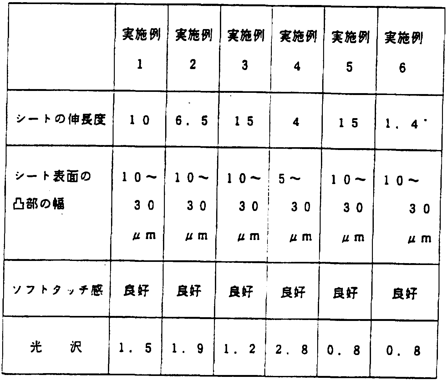
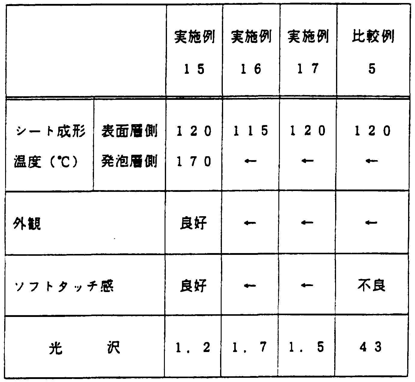


Claims
Priority Applications (7)
| Application Number | Priority Date | Filing Date | Title |
|---|---|---|---|
| AU72384/94A AU682884B2 (en) | 1994-07-29 | 1994-07-29 | Skin material having plurality of minute recesses and projections in and on its surface, method of manufacturing the same, and method of manufacturing molded products using the same skin material |
| CA002173132A CA2173132C (en) | 1994-07-29 | 1994-07-29 | Skin material having plurality of minute recesses and projections in and on its surface, method of manufacturing the same, and method of manufacturing molded products using the same skin material |
| DE69428204T DE69428204T2 (de) | 1994-07-29 | 1994-07-29 | Oberflächenmaterial, das eine vielzahl von vertiefungen und vorsprüngen in und auf seiner oberfläche aufweist, verfahren zu dessen herstellung und verfahren zum herstellen von gegenständen, die dieses oberflächenmaterial verwenden |
| US08/624,617 US5817402A (en) | 1994-07-29 | 1994-07-29 | Covering sheet having minute unevenness on the surface thereof, methods of producing said sheet and a molding using said sheet |
| PCT/JP1994/001256 WO1996004122A1 (en) | 1994-07-29 | 1994-07-29 | Skin material having plurality of minute recesses and projections in and on its surface, method of manufacturing the same, and method of manufacturing molded products using the same skin material |
| EP94921839A EP0721834B1 (en) | 1994-07-29 | 1994-07-29 | Skin material having plurality of minute recesses and projections in and on its surface, method of manufacturing the same, and method of manufacturing molded products using the same skin material |
| US09/116,081 US5997675A (en) | 1994-07-29 | 1998-07-15 | Method of molding using a covering sheet having minute unevenness on the surface thereof |
Applications Claiming Priority (1)
| Application Number | Priority Date | Filing Date | Title |
|---|---|---|---|
| PCT/JP1994/001256 WO1996004122A1 (en) | 1994-07-29 | 1994-07-29 | Skin material having plurality of minute recesses and projections in and on its surface, method of manufacturing the same, and method of manufacturing molded products using the same skin material |
Related Child Applications (1)
| Application Number | Title | Priority Date | Filing Date |
|---|---|---|---|
| US09/116,081 Division US5997675A (en) | 1994-07-29 | 1998-07-15 | Method of molding using a covering sheet having minute unevenness on the surface thereof |
Publications (1)
| Publication Number | Publication Date |
|---|---|
| WO1996004122A1 true WO1996004122A1 (en) | 1996-02-15 |
Family
ID=14098542
Family Applications (1)
| Application Number | Title | Priority Date | Filing Date |
|---|---|---|---|
| PCT/JP1994/001256 Ceased WO1996004122A1 (en) | 1994-07-29 | 1994-07-29 | Skin material having plurality of minute recesses and projections in and on its surface, method of manufacturing the same, and method of manufacturing molded products using the same skin material |
Country Status (6)
| Country | Link |
|---|---|
| US (1) | US5817402A (ja) |
| EP (1) | EP0721834B1 (ja) |
| AU (1) | AU682884B2 (ja) |
| CA (1) | CA2173132C (ja) |
| DE (1) | DE69428204T2 (ja) |
| WO (1) | WO1996004122A1 (ja) |
Families Citing this family (49)
| Publication number | Priority date | Publication date | Assignee | Title |
|---|---|---|---|---|
| US6419778B2 (en) * | 1996-05-23 | 2002-07-16 | Sekisui Kagaku Kogyo Kabushiki Kaisha | Covering sheet having minute unevenness on the surface thereof, methods of producing said sheet and a molding using said sheet |
| US6291078B1 (en) | 1997-10-22 | 2001-09-18 | Mannington Mills, Inc. | Surface coverings containing aluminum oxide |
| US6218001B1 (en) * | 1997-10-22 | 2001-04-17 | Mannington Mills, Inc. | Surface coverings containing dispersed wear-resistant particles and methods of making the same |
| US6228463B1 (en) | 1997-02-20 | 2001-05-08 | Mannington Mills, Inc. | Contrasting gloss surface coverings optionally containing dispersed wear-resistant particles and methods of making the same |
| JPH10264187A (ja) * | 1997-03-26 | 1998-10-06 | Takata Kk | 樹脂製袋体の製造方法及び樹脂製袋体 |
| DE29707311U1 (de) * | 1997-04-24 | 1997-06-19 | Löw, Wolfgang, 65468 Trebur | Textile Verbunde mit PO-Schäumen |
| US5945060A (en) * | 1997-08-01 | 1999-08-31 | Magister Corporation | Method of making latex-free elastic exercise bands |
| SE514449C2 (sv) * | 1998-10-23 | 2001-02-26 | Cleanosol Ab | Ytbeläggning avsedd att användas på markeringsbeläggningar för vägar, parkeringsplatser och liknande |
| US20030001108A1 (en) | 1999-11-05 | 2003-01-02 | Energy Sciences, Inc. | Particle beam processing apparatus and materials treatable using the apparatus |
| US7026635B2 (en) | 1999-11-05 | 2006-04-11 | Energy Sciences | Particle beam processing apparatus and materials treatable using the apparatus |
| FR2809667B1 (fr) * | 2000-05-31 | 2003-03-14 | Rollin Sa | Procede de fabrication d'un blanchet d'impression et blanchet ainsi obtenu |
| EP1186395A3 (de) * | 2000-05-31 | 2003-11-26 | CWW-GERKO Akustik GmbH & Co. KG | Verfahren zum Herstellen einer Materialbahn mit einer Butylkautschukmasse |
| FR2811213B1 (fr) * | 2000-07-07 | 2002-09-13 | Seb Sa | Boitier pour appareil electromenager de preparation culinaire prevu pour etre tenu a la main selon differentes positions |
| US6703089B2 (en) | 2000-10-06 | 2004-03-09 | Imperial Home Decor Group Management, Inc. | Bleed-resistant dry-transfer wallcoverings |
| US20080063844A1 (en) * | 2001-06-29 | 2008-03-13 | Mannington Mills, Inc. | Surface coverings containing aluminum oxide |
| WO2004067249A2 (en) * | 2003-01-27 | 2004-08-12 | Robert Lafave | Decorative system composite and method |
| FR2852551B1 (fr) * | 2003-03-21 | 2007-01-26 | Usines Gabriel Wattelez | Procede pour la fabrication d'un revetement d'isolation accoustique et/ou antivibratile |
| US7763341B2 (en) | 2004-01-23 | 2010-07-27 | Century-Board Usa, Llc | Filled polymer composite and synthetic building material compositions |
| US20060006678A1 (en) * | 2004-05-27 | 2006-01-12 | Herron Roy H Jr | Door handle cover |
| CN101111353B (zh) | 2004-06-24 | 2011-09-28 | 世纪-博得美国公司 | 用于三维泡沫产品的连续成型设备 |
| US7794224B2 (en) | 2004-09-28 | 2010-09-14 | Woodbridge Corporation | Apparatus for the continuous production of plastic composites |
| US7853454B2 (en) * | 2004-12-02 | 2010-12-14 | Laminate Products, Inc. | Method of producing a paint film part |
| US20070225419A1 (en) | 2006-03-24 | 2007-09-27 | Century-Board Usa, Llc | Polyurethane composite materials |
| US20080045101A1 (en) * | 2006-08-18 | 2008-02-21 | Near Shannon D | Decorative dual scrim composite panel |
| US20080254700A1 (en) * | 2007-04-11 | 2008-10-16 | Balthes Garry E | Process for making fibrous board |
| US20090051079A1 (en) * | 2007-08-22 | 2009-02-26 | Ronan Jeffrey J | Roofing components having vacuum-formed thermoset materials and related manufacturing methods |
| US9481759B2 (en) | 2009-08-14 | 2016-11-01 | Boral Ip Holdings Llc | Polyurethanes derived from highly reactive reactants and coal ash |
| US8846776B2 (en) | 2009-08-14 | 2014-09-30 | Boral Ip Holdings Llc | Filled polyurethane composites and methods of making same |
| TWI417187B (zh) * | 2009-09-14 | 2013-12-01 | Compal Electronics Inc | 金屬工件製作方法 |
| TWI371374B (en) * | 2009-09-14 | 2012-09-01 | Compal Electronics Inc | Production method of three dimensional pattern |
| KR20120085817A (ko) * | 2009-10-21 | 2012-08-01 | 엠지시 휠시트 가부시키가이샤 | 기능성 시트 및 그것을 이용한 렌즈 |
| JP5609324B2 (ja) * | 2010-06-30 | 2014-10-22 | 大日本印刷株式会社 | 加飾シートの製造方法、加飾シート及びそれを用いてなる加飾成形品 |
| DE102010036121A1 (de) * | 2010-09-01 | 2012-03-01 | Nora Systems Gmbh | Bodenbelag |
| TW201236887A (en) * | 2011-03-15 | 2012-09-16 | Imprinting Lithography Decoration Tech Co Ltd | Transcription method of 3D pattern solidified with UV light |
| DE202011110513U1 (de) | 2011-07-07 | 2014-05-23 | Faurecia Innenraum Systeme Gmbh | Formteil mit texturierter Oberfläche |
| WO2013052732A1 (en) | 2011-10-07 | 2013-04-11 | Boral Industries Inc. | Inorganic polymer/organic polymer composites and methods of making same |
| RU2495745C1 (ru) * | 2012-04-17 | 2013-10-20 | Адекова Марианна Дмитриевна | Способ изготовления металлопластикового изделия |
| NL2009802C2 (en) | 2012-11-13 | 2014-05-14 | Heineken Supply Chain Bv | Container, preform assembly and method and apparatus for forming containers. |
| WO2014168633A1 (en) | 2013-04-12 | 2014-10-16 | Boral Ip Holdings (Australia) Pty Limited | Composites formed from an absorptive filler and a polyurethane |
| EP2845707B1 (fr) * | 2013-09-06 | 2017-06-28 | Safran Aero Boosters SA | Maintien provisoire de tôle sur moule d'injection par soudure |
| CN104858295B (zh) * | 2014-02-25 | 2017-01-04 | 富鼎电子科技(嘉善)有限公司 | 金属外壳装饰花纹加工方法及其加工设备 |
| EP2949461B1 (de) * | 2014-05-26 | 2016-04-06 | Timonisam UG | Druckträger |
| WO2016018226A1 (en) | 2014-07-28 | 2016-02-04 | Crocco Guy | The use of evaporative coolants to manufacture filled polyurethane composites |
| WO2016022103A1 (en) | 2014-08-05 | 2016-02-11 | Amitabha Kumar | Filled polymeric composites including short length fibers |
| US9988512B2 (en) | 2015-01-22 | 2018-06-05 | Boral Ip Holdings (Australia) Pty Limited | Highly filled polyurethane composites |
| WO2016195717A1 (en) | 2015-06-05 | 2016-12-08 | Boral Ip Holdings (Australia) Pty Limited | Filled polyurethane composites with lightweight fillers |
| US20170267585A1 (en) | 2015-11-12 | 2017-09-21 | Amitabha Kumar | Filled polyurethane composites with size-graded fillers |
| JP7362221B2 (ja) * | 2020-03-17 | 2023-10-17 | 日清食品ホールディングス株式会社 | 真空および/または圧空成形容器、並びにその製造方法 |
| CN113092292B (zh) * | 2021-03-12 | 2023-07-18 | 益阳量隆能源有限公司 | 一种模拟装袋的生物质颗粒抗碎性检测装置 |
Citations (3)
| Publication number | Priority date | Publication date | Assignee | Title |
|---|---|---|---|---|
| JPS57193321A (en) * | 1981-05-25 | 1982-11-27 | Denki Kagaku Kogyo Kk | Composite biaxially oriented sheet |
| JPS5898223A (ja) * | 1981-12-09 | 1983-06-11 | Denki Kagaku Kogyo Kk | 2軸延伸スチレン系樹脂シ−ト |
| JPH02145331A (ja) * | 1988-11-28 | 1990-06-04 | Mitsui Petrochem Ind Ltd | 積層成形体およびその製造方法 |
Family Cites Families (9)
| Publication number | Priority date | Publication date | Assignee | Title |
|---|---|---|---|---|
| DE2846809A1 (de) * | 1978-10-27 | 1980-05-08 | Bayer Ag | Verfahren zur herstellung von polyurethankunststoffen |
| JPS5678148A (en) * | 1979-11-30 | 1981-06-26 | Hitachi Ltd | Resistance temperature compensation circuit |
| JPS5766936A (en) * | 1980-10-15 | 1982-04-23 | Teijin Ltd | Polyester film |
| JPS5878592A (ja) * | 1981-11-04 | 1983-05-12 | Dainippon Ink & Chem Inc | アミラ−ゼ阻害物質ki−26aおよびその製造法 |
| DE3368805D1 (en) * | 1982-03-10 | 1987-02-05 | Toray Industries | Laminated film and magnetic recording medium made therewith |
| JPS6196011A (ja) * | 1984-10-15 | 1986-05-14 | Mazda Motor Corp | 粉末合金シ−トの鉄系部材への焼結接合法 |
| DE3504671A1 (de) * | 1985-02-12 | 1986-08-14 | Bayer Ag, 5090 Leverkusen | Verfahren zur herstellung matter, nichtblockender, duennwandiger formkoerper aus linearen, thermoplastischen, polyaddukt-haltigen polyurethanelastomeren und ihre verwendung |
| JPS63192412A (ja) * | 1987-02-03 | 1988-08-09 | 高澤 弘 | メロディを発生するトイレットペ−パ−ホルダ− |
| CA2081575C (en) * | 1991-02-28 | 1997-09-23 | Akitaka Miyake | Sheet for covering a substrate and a method for producing a molding using the same |
-
1994
- 1994-07-29 AU AU72384/94A patent/AU682884B2/en not_active Ceased
- 1994-07-29 EP EP94921839A patent/EP0721834B1/en not_active Expired - Lifetime
- 1994-07-29 US US08/624,617 patent/US5817402A/en not_active Expired - Fee Related
- 1994-07-29 WO PCT/JP1994/001256 patent/WO1996004122A1/ja not_active Ceased
- 1994-07-29 CA CA002173132A patent/CA2173132C/en not_active Expired - Fee Related
- 1994-07-29 DE DE69428204T patent/DE69428204T2/de not_active Expired - Fee Related
Patent Citations (3)
| Publication number | Priority date | Publication date | Assignee | Title |
|---|---|---|---|---|
| JPS57193321A (en) * | 1981-05-25 | 1982-11-27 | Denki Kagaku Kogyo Kk | Composite biaxially oriented sheet |
| JPS5898223A (ja) * | 1981-12-09 | 1983-06-11 | Denki Kagaku Kogyo Kk | 2軸延伸スチレン系樹脂シ−ト |
| JPH02145331A (ja) * | 1988-11-28 | 1990-06-04 | Mitsui Petrochem Ind Ltd | 積層成形体およびその製造方法 |
Non-Patent Citations (1)
| Title |
|---|
| See also references of EP0721834A4 * |
Also Published As
| Publication number | Publication date |
|---|---|
| EP0721834A1 (en) | 1996-07-17 |
| EP0721834A4 (en) | 1997-04-16 |
| CA2173132A1 (en) | 1996-02-15 |
| AU7238494A (en) | 1996-03-04 |
| EP0721834B1 (en) | 2001-09-05 |
| US5817402A (en) | 1998-10-06 |
| DE69428204D1 (de) | 2001-10-11 |
| DE69428204T2 (de) | 2002-06-13 |
| CA2173132C (en) | 2005-03-15 |
| AU682884B2 (en) | 1997-10-23 |
Similar Documents
| Publication | Publication Date | Title |
|---|---|---|
| WO1996004122A1 (en) | Skin material having plurality of minute recesses and projections in and on its surface, method of manufacturing the same, and method of manufacturing molded products using the same skin material | |
| WO1992015636A1 (fr) | Feuille de revetement et procede de realisation d'objets moules utilisant cette feuille | |
| US6419778B2 (en) | Covering sheet having minute unevenness on the surface thereof, methods of producing said sheet and a molding using said sheet | |
| US5407991A (en) | Thermoplastic elastomer composition, covering materials for industrial parts comprising the composition and laminates comprising the covering materials | |
| JP3335564B2 (ja) | 成形用シートおよびその製造方法 | |
| US5997675A (en) | Method of molding using a covering sheet having minute unevenness on the surface thereof | |
| JP3212397B2 (ja) | 被覆用シート及びその製造方法 | |
| JP3272171B2 (ja) | 被覆用シートの製造方法 | |
| JP3169478B2 (ja) | 被覆用シートおよびその製造方法 | |
| JP3139939B2 (ja) | 熱成形用積層シート及びその製造方法 | |
| JP3217175B2 (ja) | 被覆用シートの製造方法 | |
| JP3345076B2 (ja) | 成形品の製造方法 | |
| JP3502488B2 (ja) | 積層シート | |
| JP3135479B2 (ja) | 積層シート及びその製造方法 | |
| JPH07164537A (ja) | 発泡成形体の製造方法 | |
| JP3294947B2 (ja) | 被覆用シート及びその製造方法 | |
| JPH06190864A (ja) | 積層用シートおよびこのシートを用いた積層成形品の製造方法 | |
| JP3212403B2 (ja) | 積層用シートおよび積層成形品の製造方法 | |
| JP3392265B2 (ja) | 積層シート | |
| JP3357182B2 (ja) | 被覆用シートの製造方法 | |
| JPH11157023A (ja) | 積層シート | |
| JP3320548B2 (ja) | 発泡積層体と発泡成形体の製造方法 | |
| JP3231180B2 (ja) | 被覆成形品の製造方法 | |
| JPH09295377A (ja) | 積層体 | |
| JP2000108261A (ja) | 成形体 |
Legal Events
| Date | Code | Title | Description |
|---|---|---|---|
| AK | Designated states |
Kind code of ref document: A1 Designated state(s): AU CA US |
|
| AL | Designated countries for regional patents |
Kind code of ref document: A1 Designated state(s): DE FR GB IT NL |
|
| WWE | Wipo information: entry into national phase |
Ref document number: 2173132 Country of ref document: CA |
|
| WWE | Wipo information: entry into national phase |
Ref document number: 1994921839 Country of ref document: EP |
|
| 121 | Ep: the epo has been informed by wipo that ep was designated in this application | ||
| WWE | Wipo information: entry into national phase |
Ref document number: 08624617 Country of ref document: US |
|
| WWP | Wipo information: published in national office |
Ref document number: 1994921839 Country of ref document: EP |
|
| WWG | Wipo information: grant in national office |
Ref document number: 1994921839 Country of ref document: EP |